

Kikusui TOS9213S, TOS9213AS Operation Manual
Part No. Z1-004-642, IB019757
Jul. 2018
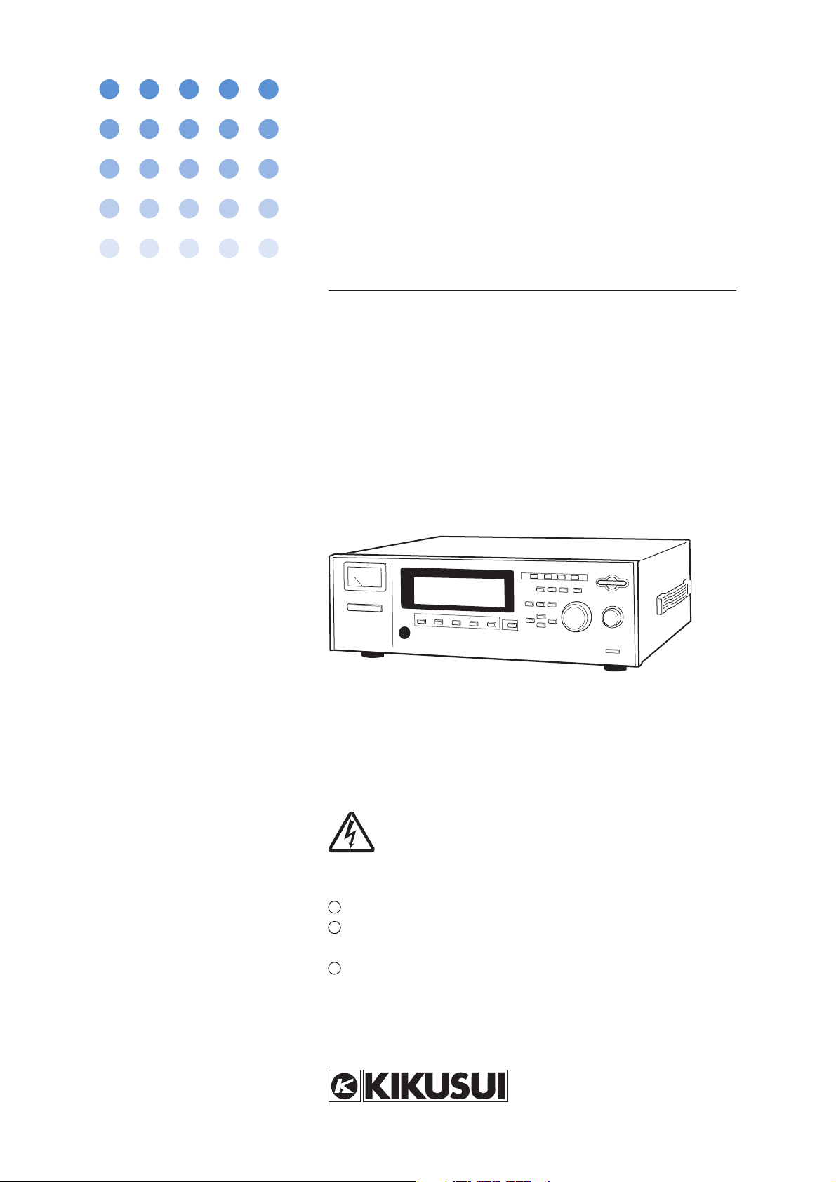
OPERATION MANUAL
DC WITHSTANDING VOLTAGE/
INSULATION RESISTANCE TESTER
TOS9200 Series
TOS9213S
(SPEC80623)
TOS9213AS
(SPEC80767)
DANGER
This Tester generates high voltage.
Any incorrect handling may cause death.
Read Chapter 3 “Precautions on Handling” in
this manual to prevent accident.
Keep this manual near the tester for easy
access of the operator.

Use of Operation Manual
Please read through and understand this Operation Manual before operating the product. After reading, always
keep the manual nearby so that you may refer to it as needed. When moving the product to another location,
be sure to bring the manual as well.
If you find any incorrectly arranged or missing pages in this manual, they will be replaced. If the manual it
gets lost or soiled, a new copy can be provided for a fee. In either case, please contact Kikusui distributor/
agent, and provide the “Kikusui Part No.” given on the cover.
This manual has been prepared with the utmost care; however, if you have any questions, or note any errors or
omissions, please contact Kikusui distributor/agent.
Disposing of used Kikusui products in the EU
Under a law adopted by member nations of the European Union (EU), used electric and electronic products
carrying the symbol below must be disposed of separately from general household waste.
This includes the power cords and other accessories bundled with the products. When
disposing of a product subject to these regulations, please follow the guidance of your
local authority, or inquire with your Kikusui distributor/agent where you purchased the
product.
The symbol applies only to EU member nations.
Disposal outside the EU
When disposing of an electric or electronic product in a country that is not an EU member, please contact your
local authority and ask for the correct method of disposal.
The other company names and product names that appear in this manual are the trademarks or registered
trademarks of the respective manufacturers.
Reproduction and reprinting of this operation manual, whole or partially, without our permission is prohibited.
Both unit specifications and manual contents are subject to change without notice.
Copyright© 2009 Kikusui Electronics Corporation
Interlock Function
The first time the tester is turned on following delivery, the interlock
function activates and testing is disabled.
Before starting a test, read "6.3 INTERLOCK Connector" for the
procedure for starting up the tester using the interlock function.
About this manual
This operation manual describes the withstanding voltage tester
TOS9213S and TOS9213AS.
This manual is applicable to the Tester whose ROM version
number is:
Ver. 1.4x
Yo u can check the version number on the opening screen at turning on the power
or by using the *IDN? message.
For the *IDN? message, see "7.4.1 Register-Related Messages and General Purpose
Messages."
When you contact us for any information about the Tester, please indicate
the ROM version number and serial number of the Tester. The serial number
is shown on the rear panel of the Tester.
The opening screen (Example of ROM version is 1.20)
TOS9213S
DC WITHSTANDING VOLTAGE /
INSULATION RESISTANCE TESTER
Ver. 1.20
KIKUSUI ELECTRONICS CORP.
TOS9213S/ TOS9213AS i
To supervisor in charge of operation
• If the operator does not read the language used in this manual, translate the manual into appropriate language.
• Help the operator in understanding this manual before operation.
• Keep this manual near the tester for easy access of the operator.
For your own safety (to avoid electrification)
While the tester is delivering its test voltage, never touch the following areas, or else, you will be
electrified, and run the risk of death by electric shock.
•the output terminal
• the test leadwires connected to the output terminal
•the Device Under Test (DUT)
• any part of the tester, w hich is electrically connected to the output terminal, and
• the same part as above immediately after the output has been cut off when in the DC mode of
test.
Also, electric shock or accident may arise in the following cases:
• the tester being operated without grounding.
• if the gloves for electrical job are not used.
• approach to any part connected to the output terminal while the power of the tester is turned
on.
• the same action as above immediately after the power of tester has been turn
DC mode of test.
ed off whe
n in the
ii TOS9213S/ TOS9213AS
Power Requirements of this Product
✓
WARNING
Power requirements of this product have been changed and the relevant sections of the Operation
Manual should be revised accordingly.
(Revision should be applied to items indicated by a check mark .)
Input voltage
The input voltage of this product is VAC,
and the voltage range is
Input fuse
The rating of this product's input fuse is A, VAC, and .
•To avoid electrical shock, always disconnect the AC power cord or turn off
the switch on the switchboard before attempting to check or replace the
fuse.
•Use a fuse element having a shape, rating, and characteristics suitable
for this product. The use of a fuse with a different rating or one that short
circuits the fuse holder may result in fire, electric shock, or irreparable
damage.
to VAC. Use the product within this range only.
TOS9213S/ TOS9213AS iii
For the safe use and safe maintenance of this product, the following
symbols are used throughout this manual and on the product. Understand the meanings of the symbols and observe the instructions they
indicate (the choice of symbols used depends on the products).
OR
WARNING
CAUTION
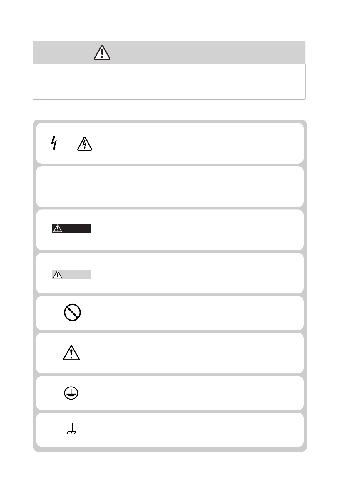
Safety Symbols
Indicates that a high voltage (over 1000 V) is used here. Touch-
ing the part causes a possibly fatal electric shock. If physical
contact is required by your work, start work only after you make
sure that no voltage is output here.
DANGER
Indicates an imminently hazardous situation which, if ignored,
will result in death or serious injury.
Indicates a potentially hazardous situation which, if ignored,
could result in death or serious injury.
Indicates a potentially hazardous situation which, if ignored, may
result in damage to the product and other property.
Shows that the act indicated is prohibited.
Is placed before the sign “DANGER,” “WARNING,” or “CAUTION” to emphasize these. When this symbol is marked on
pro
duct, see the relevant sections in this manual.
the
Indicates a protective conductor terminal.
Indicates a chassis(frame) terminal.
iv Safety Symbols TOS9213S/ TOS9213AS
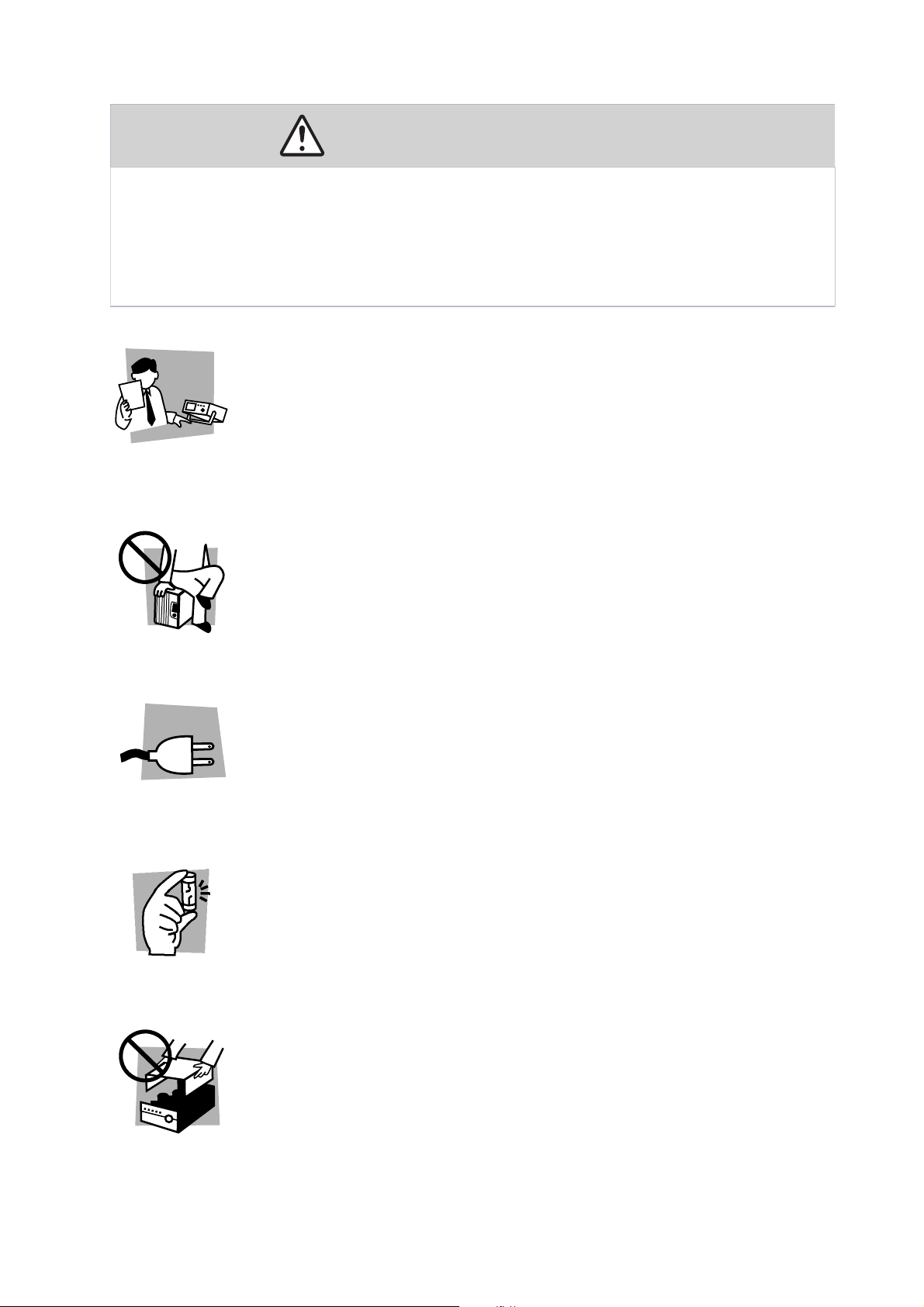
Safety Precautions
Operation
Manual
Line
Voltage
The following safety precautions must be observed to avoid fire hazard,
electrical shock, accidents, and other failures. Keep them in mind and
make sure that all of them are observed properly. Using the product in a
manner that is not specified in this manual may impair the protection
functions provided by the product.
Users
• This product must be used only by qualified personnel who understand the contents of this operation manual.
• If it is handled by disqualified personnel, personal injury may result. Be sure to handle it under supervision of qualified personnel (those who have electrical knowl-
edge.)
Purposes of use
• Do not use the product for purposes other than those described in the operation
manual.
• This product is not designed or manufactured for general home or consumer use.
Input power
• Use the product with the specified input power voltage.
• For applying power, use the AC power cord provided.
• This product is an equipment of IEC Overvoltage Category II (energy-consuming
equipment supplied from the fixed installation).
Fuse
•The fuse can be replaced with a new one. When replacing a fuse, use the one
which has appropriate shape, ratings, and specifications.
Cover
• There are parts inside the product which may cause physical hazards. Do not
remove the external cover.
TOS9213S/ TOS9213AS v
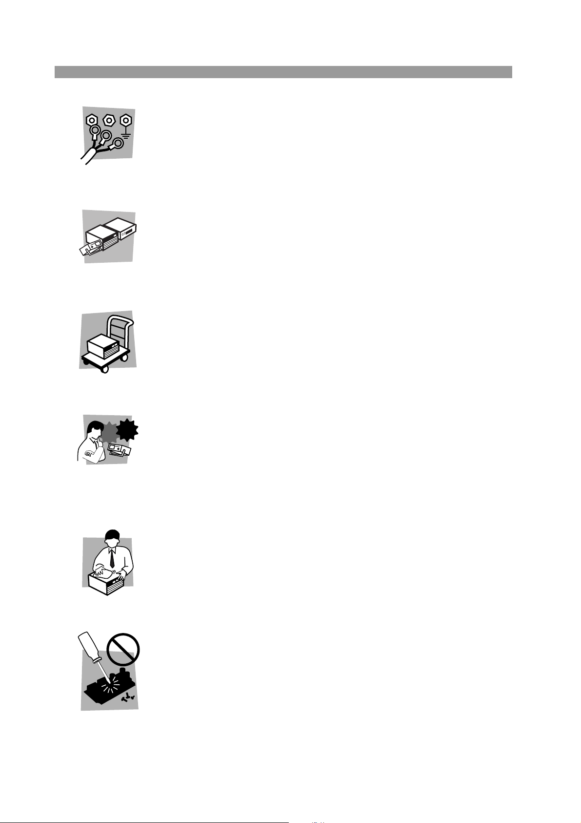
Grounding
GNL
Check?
• This product is an IEC Safety Class I equipment (equipment with a protective conductor terminal). To prevent electric shock, be sure to connect the protective conductor terminal of the product to electrical ground (safety ground).
Installation
• This product is designed for safe indoor use. Be sure to use the product indoors.
• When installing products, be sure to observe precautions concerning installation
location. For details, see the respective page in the operation manual.
Relocation
•Turn off the power switch and then disconnect all cables when relocating the prod-
uct.
•Be sure the operation manual be included when the product is relocated.
Operation
• If any abnormality or failure is detected in the products, stop using it immediately.
Unplug the AC power cord. Be careful not to allow the product to be used before it
is completely repaired.
• Do not disassemble or modify the product. If it must be modified, contact Kikusui
distributor/agent.
Maintenance and checking
•To avoid electrical shock, be absolutely sure to unplug the AC power cord before
performing maintenance or checking. Do not remove the cover.
• To maintain performance and safe operation of the product, it is recommended that
periodic maintenance, checking, cleaning, and calibration be performed.
Service
• Internal service is to be done by Kikusui service engineers. If the product must be
adjusted or repaired, contact Kikusui distributor/agent.
vi TOS9213S/ TOS9213AS
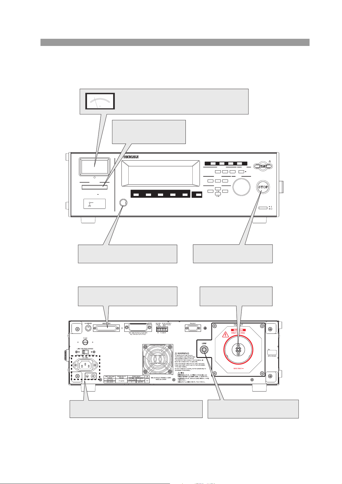
Front panel and Rear panel
OUTPUT
AUTO
RECALL
ENTER
DCW IR SYSTEM LOCAL
TEST
FUNCTION GPIB
PASS FAIL
MEMORY ENTRY
CURSOR
REMOTE
PROTECTION
RMT
FF
5
F
4
F
3
F
2
F
1
PREV NEXT
EDIT
STORE
I
/
F KEY LOCK
SHIFSHIFT
DANGER
DC WITHSTANDING VOLTAGE
/
INSULATION RESISTANCE TESTER
TOS9213S
HIGH VOLTAGE
TERMINAL
LOW
MAX10kV
Before using the remote-control
function, read the Operation Manual.
For connection, begin with the test
leadwire of the low-voltage level.
Deflected meter pointer means that the Tester is in
“DANGER HIGH VOLTAGE” state.
Lighted lamp means that
the Tester is in “DANGER
HIGH VOLTAGE” state.
To ensure safety, be sure to connect to an earth
ground.See “2.5 Connecting the AC Power Cord.”
Before using the remote-control
function, read the Operation Manual.
To change testing conditions,
press the STOP button.
DANGER
HIGH VOLTAGE terminal
• Before using the tester, be sure to read Chapter3 "Precautions on Handling"
TOS9213S/ TOS9213AS vii

Description of Contents
This manual is composed of the following chapters:
Chapter 1 Preface
This section provides an outline of the tester and explains its features and options.
Chapter 2 Setup
This chapter describes the procedures from unpacking to installation to operation
checking.
Chapter 3 Precautions on Handling
This chapter describes the precautions to be followed in the handling of this tester.
When using the tester, take utmost care to ensure safety.
Chapter 4 Part names and Functions
This chapter describes the names and functions of components such as switches,
displays, and connectors on the front and rear panels.
Chapter 5 Basic Operations
This chapter describes the procedures for conducting withstanding voltage and insulation resistance tests.
Chapter 6 Using Terminals and Connectors
This chapter describes the procedures for use of the connectors on the front and rear
panels.
Chapter 7 GPIB/RS-232C Interface
This chapter describes the GPIB and RS-232C interfaces and the device messages.
Chapter 8 Controlling the TOS6200
This chapter describes the procedure for using the tester to control Kikusui’s earth
continuity tester TOS6200 via the RS-232C interface.
Chapter 9 Maintenance
This chapter describes the maintenance, inspection, and calibration of the tester.
Chapter 10 Specifications
This chapter describes the electrical and mechanical specifications for the tester.
Appendix
Appendix describes the operating principle of the tester and ASCII code table (20H
to 7EH).
viii TOS9213S/ TOS9213AS
Contents
Safety Symbols - - - - - - - - - - - - - - - - - - - - - - - - - - - - - - - - - - - - - - - - - - - - - iv
Safety Precautions- - - - - - - - - - - - - - - - - - - - - - - - - - - - - - - - - - - - - - - - - - - v
Chapter 1 Preface
1.1 Outline - - - - - - - - - - - - - - - - - - - - - - - - - - - - - - - - - - - - - - - - - - - - - - - - - 1-2
1.2 Features - - - - - - - - - - - - - - - - - - - - - - - - - - - - - - - - - - - - - - - - - - - - - - - - 1-4
1.3 Options - - - - - - - - - - - - - - - - - - - - - - - - - - - - - - - - - - - - - - - - - - - - - - - - - 1-8
Chapter 2 Setup
2.1 Unpacking - - - - - - - - - - - - - - - - - - - - - - - - - - - - - - - - - - - - - - - - - - - - - - - 2-2
2.2 Precautions for Installation - - - - - - - - - - - - - - - - - - - - - - - - - - - - - - - - - - - 2-3
2.3 Precautions for Moving- - - - - - - - - - - - - - - - - - - - - - - - - - - - - - - - - - - - - - 2-4
2.4 Checking the Line Voltage and Fuse - - - - - - - - - - - - - - - - - - - - - - - - - - - - 2-5
2.4.1 Switching source voltages - - - - - - - - - - - - - - - - - - - - - - - - - - - - - - - 2-5
2.4.2 Checking and replacing fuses - - - - - - - - - - - - - - - - - - - - - - - - - - - - 2-6
2.5 Connecting the AC Power Cord - - - - - - - - - - - - - - - - - - - - - - - - - - - - - - - 2-7
2.6 Checking Operations - - - - - - - - - - - - - - - - - - - - - - - - - - - - - - - - - - - - - - - 2-9
Chapter 3 Precautions on Handling
Chap. 1Chap. 2Chap. 3Chap. 4Chap. 5Chap. 6Chap. 7Chap. 8Appendix Chap. 9Chap. 10
3.1 Prohibited Operations - - - - - - - - - - - - - - - - - - - - - - - - - - - - - - - - - - - - - - 3-2
3.2 Action When in Emergency- - - - - - - - - - - - - - - - - - - - - - - - - - - - - - - - - - - 3-2
3.3 Precautions on Testing - - - - - - - - - - - - - - - - - - - - - - - - - - - - - - - - - - - - - - 3-3
3.4 Warning for Residual High Voltages - - - - - - - - - - - - - - - - - - - - - - - - - - - - 3-4
3.5 Dangerous States of Failed Tester - - - - - - - - - - - - - - - - - - - - - - - - - - - - - 3-5
3.6 To Ensure Long-Term Use Without Failures- - - - - - - - - - - - - - - - - - - - - - - 3-6
3.7 Daily Checking - - - - - - - - - - - - - - - - - - - - - - - - - - - - - - - - - - - - - - - - - - - 3-6
Chapter 4 Part names and Functions
4.1 Front Panel - - - - - - - - - - - - - - - - - - - - - - - - - - - - - - - - - - - - - - - - - - - - - - 4-2
4.2 Rear Panel - - - - - - - - - - - - - - - - - - - - - - - - - - - - - - - - - - - - - - - - - - - - - - 4-6
Chapter 5 Basic Operations
5.1 Turning on the Power - - - - - - - - - - - - - - - - - - - - - - - - - - - - - - - - - - - - - - - 5-2
5.2 Pre-Test Zero Adjustment- - - - - - - - - - - - - - - - - - - - - - - - - - - - - - - - - - - - 5-3
5.3 Structure of LCD Screen - - - - - - - - - - - - - - - - - - - - - - - - - - - - - - - - - - - - 5-4
5.4 Settings for DC Withstanding Voltage Testing - - - - - - - - - - - - - - - - - - - - - 5-5
5.4.1 Settings on the DCW1 screen - - - - - - - - - - - - - - - - - - - - - - - - - - - - 5-6
5.4.2 Settings on the DCW2 screen - - - - - - - - - - - - - - - - - - - - - - - - - - - 5-10
5.4.3 Settings on the DCW3 screen - - - - - - - - - - - - - - - - - - - - - - - - - - - 5-18
5.5 Settings for Insulation Resistance Testing - - - - - - - - - - - - - - - - - - - - - - - 5-20
5.5.1 Settings on the IR1 screen - - - - - - - - - - - - - - - - - - - - - - - - - - - - - 5-21
5.5.2 Settings on the IR2 screen - - - - - - - - - - - - - - - - - - - - - - - - - - - - - 5-28
5.5.3 Settings on the IR3 screen - - - - - - - - - - - - - - - - - - - - - - - - - - - - - 5-34
5.6 Connecting the Test Leadwire- - - - - - - - - - - - - - - - - - - - - - - - - - - - - - - - 5-36
TOS9213S/ TOS9213AS ix

5.6.1 Connecting the test leadwire to the tester - - - - - - - - - - - - - - - - - - - 5-36
5.6.2 Connecting a DUT- - - - - - - - - - - - - - - - - - - - - - - - - - - - - - - - - - - - 5-36
5.7 Starting and Ending a Test - - - - - - - - - - - - - - - - - - - - - - - - - - - - - - - - - - 5-38
5.7.1 Starting a test - - - - - - - - - - - - - - - - - - - - - - - - - - - - - - - - - - - - - - - 5-38
5.7.2 Ending the test - - - - - - - - - - - - - - - - - - - - - - - - - - - - - - - - - - - - - - 5-40
5.8 System Settings - - - - - - - - - - - - - - - - - - - - - - - - - - - - - - - - - - - - - - - - - - 5-43
5.8.1 SYSTEM 1 - - - - - - - - - - - - - - - - - - - - - - - - - - - - - - - - - - - - - - - - - 5-43
5.8.2 SYSTEM2 - - - - - - - - - - - - - - - - - - - - - - - - - - - - - - - - - - - - - - - - - 5-45
5.8.3 SYSTEM3 - - - - - - - - - - - - - - - - - - - - - - - - - - - - - - - - - - - - - - - - - 5-47
5.8.4 SYSTEM4 - - - - - - - - - - - - - - - - - - - - - - - - - - - - - - - - - - - - - - - - - 5-48
5.9 Interface Settings - - - - - - - - - - - - - - - - - - - - - - - - - - - - - - - - - - - - - - - - - 5-49
5.10 Panel Memory - - - - - - - - - - - - - - - - - - - - - - - - - - - - - - - - - - - - - - - - - - - 5-50
5.10.1Storage in the panel memory - - - - - - - - - - - - - - - - - - - - - - - - - - - - 5-50
5.10.2Recalling panel memory - - - - - - - - - - - - - - - - - - - - - - - - - - - - - - - 5-51
5.11 Program - - - - - - - - - - - - - - - - - - - - - - - - - - - - - - - - - - - - - - - - - - - - - - - 5-52
5.11.1Creating and editing a program - - - - - - - - - - - - - - - - - - - - - - - - - - 5-53
5.11.2Executing a program - - - - - - - - - - - - - - - - - - - - - - - - - - - - - - - - - - 5-55
5.11.3Suspending the program - - - - - - - - - - - - - - - - - - - - - - - - - - - - - - - 5-55
5.11.4Judgement on the program - - - - - - - - - - - - - - - - - - - - - - - - - - - - - 5-56
5.11.5Exiting the program - - - - - - - - - - - - - - - - - - - - - - - - - - - - - - - - - - - 5-56
5.12 Key Lock - - - - - - - - - - - - - - - - - - - - - - - - - - - - - - - - - - - - - - - - - - - - - - - 5-57
5.13 Invalid Settings- - - - - - - - - - - - - - - - - - - - - - - - - - - - - - - - - - - - - - - - - - - 5-57
5.14 Protection - - - - - - - - - - - - - - - - - - - - - - - - - - - - - - - - - - - - - - - - - - - - - - 5-58
5.15 Initialization - - - - - - - - - - - - - - - - - - - - - - - - - - - - - - - - - - - - - - - - - - - - - 5-62
Chapter 6 Using Terminals and Connectors
6.1 REMOTE Terminal - - - - - - - - - - - - - - - - - - - - - - - - - - - - - - - - - - - - - - - - 6-2
6.2 SIGNAL I/O Connector - - - - - - - - - - - - - - - - - - - - - - - - - - - - - - - - - - - - - - 6-4
6.2.1 Specifications for the SIGNAL I/O connector - - - - - - - - - - - - - - - - - - 6-5
6.2.2 Example- - - - - - - - - - - - - - - - - - - - - - - - - - - - - - - - - - - - - - - - - - - - 6-7
6.2.3 Starting a test - - - - - - - - - - - - - - - - - - - - - - - - - - - - - - - - - - - - - - - - 6-8
6.2.4 Recalling the panel memory and programs - - - - - - - - - - - - - - - - - - 6-10
6.3 INTERLOCK Connector - - - - - - - - - - - - - - - - - - - - - - - - - - - - - - - - - - - - 6-12
6.4 STATUS OUT Connector - - - - - - - - - - - - - - - - - - - - - - - - - - - - - - - - - - - 6-14
Chapter 7 GPIB/RS-232C Interface
7.1 GPIB Interface - - - - - - - - - - - - - - - - - - - - - - - - - - - - - - - - - - - - - - - - - - - - 7-2
7.1.1 Connecting the GPIB cable - - - - - - - - - - - - - - - - - - - - - - - - - - - - - - 7-2
7.1.2 Setting the GPIB address- - - - - - - - - - - - - - - - - - - - - - - - - - - - - - - - 7-3
7.2 RS-232C Interface - - - - - - - - - - - - - - - - - - - - - - - - - - - - - - - - - - - - - - - - - 7-4
7.2.1 Connecting the RS-232C cable - - - - - - - - - - - - - - - - - - - - - - - - - - - 7-4
7.2.2 RS-232C settings - - - - - - - - - - - - - - - - - - - - - - - - - - - - - - - - - - - - - 7-4
7.2.3 RS-232C flow control- - - - - - - - - - - - - - - - - - - - - - - - - - - - - - - - - - - 7-6
7.3 Messages and Terminators - - - - - - - - - - - - - - - - - - - - - - - - - - - - - - - - - - - 7-7
7.3.1 Messages- - - - - - - - - - - - - - - - - - - - - - - - - - - - - - - - - - - - - - - - - - - 7-7
7.3.2 Terminators - - - - - - - - - - - - - - - - - - - - - - - - - - - - - - - - - - - - - - - - - 7-9
7.3.3 Special symbols and characters - - - - - - - - - - - - - - - - - - - - - - - - - - - 7-9
7.4 Device Messages - - - - - - - - - - - - - - - - - - - - - - - - - - - - - - - - - - - - - - - - - 7-10
7.4.1 Register-related messages and general purpose messages - - - - - - 7-10
7.4.2 Messages used exclusively for DC withstanding voltage testing - - - 7-16
x TOS9213S/ TOS9213AS
7.4.3 Messages used exclusively for insulation resistance testing - - - - - - 7-24
7.4.4 Messages common to all tests - - - - - - - - - - - - - - - - - - - - - - - - - - - 7-33
7.4.5 System-related messages - - - - - - - - - - - - - - - - - - - - - - - - - - - - - - 7-36
7.4.6 Memory-related messages - - - - - - - - - - - - - - - - - - - - - - - - - - - - - 7-44
7.4.7 Program-related messages - - - - - - - - - - - - - - - - - - - - - - - - - - - - - 7-50
7.5 Registers - - - - - - - - - - - - - - - - - - - - - - - - - - - - - - - - - - - - - - - - - - - - - - 7-56
7.6 Message List- - - - - - - - - - - - - - - - - - - - - - - - - - - - - - - - - - - - - - - - - - - - 7-60
7.6.1 Register-related messages and general messages - - - - - - - - - - - - 7-60
7.6.2 Messages for DC withstanding voltage testing - - - - - - - - - - - - - - - 7-61
7.6.3 Messages for insulation resistance testing - - - - - - - - - - - - - - - - - - 7-62
7.6.4 Messages common to all tests - - - - - - - - - - - - - - - - - - - - - - - - - - - 7-63
7.6.5 System-related messages - - - - - - - - - - - - - - - - - - - - - - - - - - - - - - 7-64
7.6.6 Memory-related messages - - - - - - - - - - - - - - - - - - - - - - - - - - - - - 7-66
7.6.7 Program-related messages - - - - - - - - - - - - - - - - - - - - - - - - - - - - - 7-68
Chapter 8 Controlling the TOS6200
8.1 Pre-Control Preparation - - - - - - - - - - - - - - - - - - - - - - - - - - - - - - - - - - - - - 8-2
8.1.1 Connection and startup procedure - - - - - - - - - - - - - - - - - - - - - - - - - 8-2
8.1.2 Settings on the TOS6200 - - - - - - - - - - - - - - - - - - - - - - - - - - - - - - - 8-2
8.1.3 Settings on the TOS9213S/ TOS9213AS - - - - - - - - - - - - - - - - - - - - 8-3
8.2 Starting a Test - - - - - - - - - - - - - - - - - - - - - - - - - - - - - - - - - - - - - - - - - - - - 8-6
8.3 Test Judgement- - - - - - - - - - - - - - - - - - - - - - - - - - - - - - - - - - - - - - - - - - - 8-7
8.4 Canceling the TOS6200 Control Mode- - - - - - - - - - - - - - - - - - - - - - - - - - - 8-8
Chap. 1Chap. 2Chap. 3Chap. 4Chap. 5Chap. 6Chap. 7Chap. 8Appendix Chap. 9Chap. 10
Chapter 9 Maintenance
9.1 Cleaning - - - - - - - - - - - - - - - - - - - - - - - - - - - - - - - - - - - - - - - - - - - - - - - - 9-2
9.2 Inspection - - - - - - - - - - - - - - - - - - - - - - - - - - - - - - - - - - - - - - - - - - - - - - - 9-2
9.3 Maintenance - - - - - - - - - - - - - - - - - - - - - - - - - - - - - - - - - - - - - - - - - - - - - 9-3
9.4 Calibration- - - - - - - - - - - - - - - - - - - - - - - - - - - - - - - - - - - - - - - - - - - - - - - 9-3
9.5 Troubleshooting- - - - - - - - - - - - - - - - - - - - - - - - - - - - - - - - - - - - - - - - - - - 9-4
Chapter 10 Specifications
10.1 Withstanding Voltage Test Mode - - - - - - - - - - - - - - - - - - - - - - - - - - - - - - 10-2
10.2 Insulation Resistance Testing Mode - - - - - - - - - - - - - - - - - - - - - - - - - - - 10-5
10.3 Interface and Other Functions - - - - - - - - - - - - - - - - - - - - - - - - - - - - - - - - 10-8
10.4 General Specifications - - - - - - - - - - - - - - - - - - - - - - - - - - - - - - - - - - - - -10-11
10.5 Dimensions - - - - - - - - - - - - - - - - - - - - - - - - - - - - - - - - - - - - - - - - - - - - -10-12
Appendix
A.1 Operating Principle - - - - - - - - - - - - - - - - - - - - - - - - - - - - - - - - - - - - - - - - A-1
A.2 ASCII Code 20H to 7EH - - - - - - - - - - - - - - - - - - - - - - - - - - - - - - - - - - - - - A-3
Index
TOS9213S/ TOS9213AS xi

xii TOS9213S/ TOS9213AS

Chapter 1 Preface
Chap. 1
Preface
This section provides an outline of the tester and explains its features and options.
TOS9213S/ TOS9213AS 1-1

1.1 Outline
The TOS9213S/ TOS9213AS (hereinafter referred to as “the tester”) is withstanding
voltage/insulation resistance tester. The tester can perform DC withstanding voltage
testing and insulation resistance testing. The tester can operate at up to 10 kVDC (at
a maximum output of 50 W for up to 1 minute) in DC withstanding voltage testing.
The tester is capable of performing withstanding voltage testing on electronic equipment and components in accordance with safety standards, including IEC, EN,
VDE, BS, UL, CSA, JIS, and the Electrical Appliance and Material Safety Law (in
Japan.)
The high-voltage block features a high-efficiency switching power supply and a
PWM-based switching amplifier. This ensures high and stable output extremely
resistant to power-supply and load fluctuations.
Because the tester boasts measurement accuracy that enables it to handle high-resolution current measurements and judgements of values as small as tens of µA, it is
ideal for testing solar panels (photovoltaic panels) and other devices.
For insulation resistance testing, TOS9213S is compatible with the test voltage
range of 25 V to 1000 V (at a resolution of 1 V) and the resistance measuring range
of 0.01 M
whereas TOS9213AS is compatible with the test voltage range of 25 V to 1500 V
(at a resolution of 1V) and the resistance measuring range of 0.01 M
(at rated current range of 50nA to 1 mA maximum, or at rated current range of 50
nA to 0.1 mA if the test voltage setting exceeds 1020 V).
Not only can the tester make judgements using insulation resistance values, it can
also make judgments using measurements of the leakage current that flows through
the insulation resistance.
Once connected to a DUT, the tester can not only perform DC withstanding voltage
tests, and insulation resistance tests separately, but can also conduct these tests consecutively using the program function. When combined with the high-voltage scanner TOS9221/TOS9220, each tester can operate using four channels. The tester can
be connected to four scanners, thus permitting the connection of a total of 16 channels. Further, when used together with the earth continuity tester TOS6200, the tester can also be applied to safety tests such as earth continuity tests. (When combined
with the scanner, the output voltage is up to 6 kV.)
The tester is equipped with GPIB and RS-232C as standard features, making them
highly applicable to a variety of automatic testing systems that require greater safety
and reliability.
Ω to 9.99 GΩ (at rated current range of 50 nA to 1 mA maximum),
Ω to 9.99 GΩ
1-2 TOS9213S/ TOS9213AS
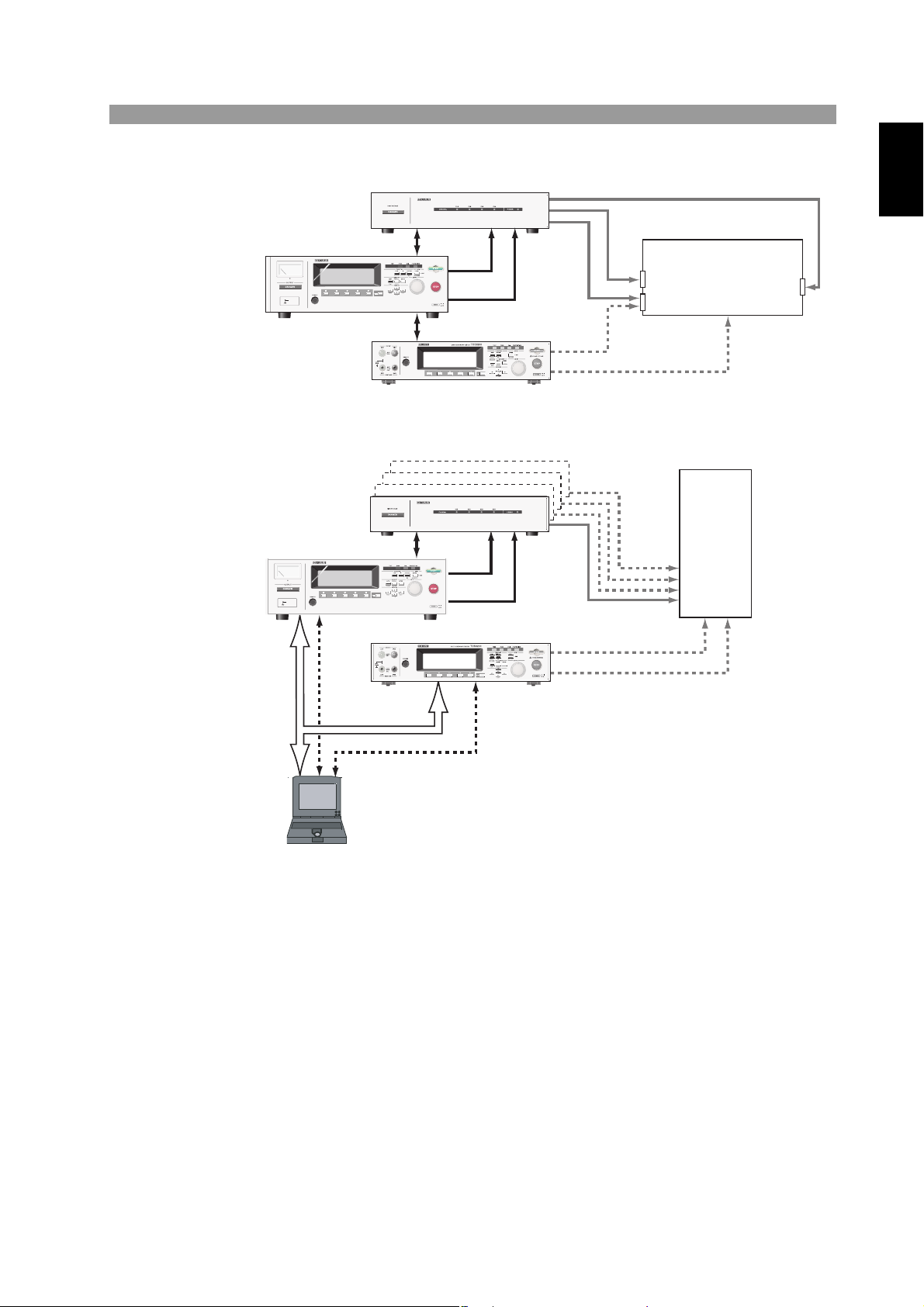
Example of system application 1
SCAN I/F
Maximum of
16 channels
RS-232C
RS-232C
GPIB
H.V
LOW
DUT
TOS9220/9221
TOS9213S/9213AS
TOS6200
DC WITHSTANDING VOLTAGE/
INSULATION RESISTANCE TESTER
TOS9213S
TERMINAL
LOW
TOS9220/9221
Chap. 1
TOS9213S/9213AS
SCAN I/F
H.V
TERMINAL
LOW
DC WITHSTANDING VOLTAGE/
INSULATION RESISTANCE TESTER
TOS9213S
LOW
RS-232C
TOS6200
Example of system application 2
DUT
Switching power supply
Switching
power supply
GND
terminal
Frame
Output
terminal
Preface
TOS9213S/ TOS9213AS 1-3
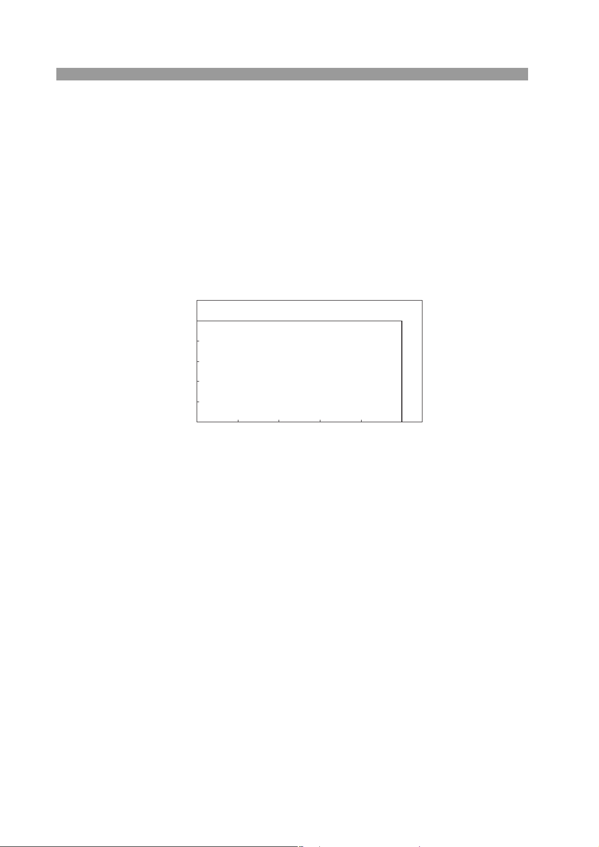
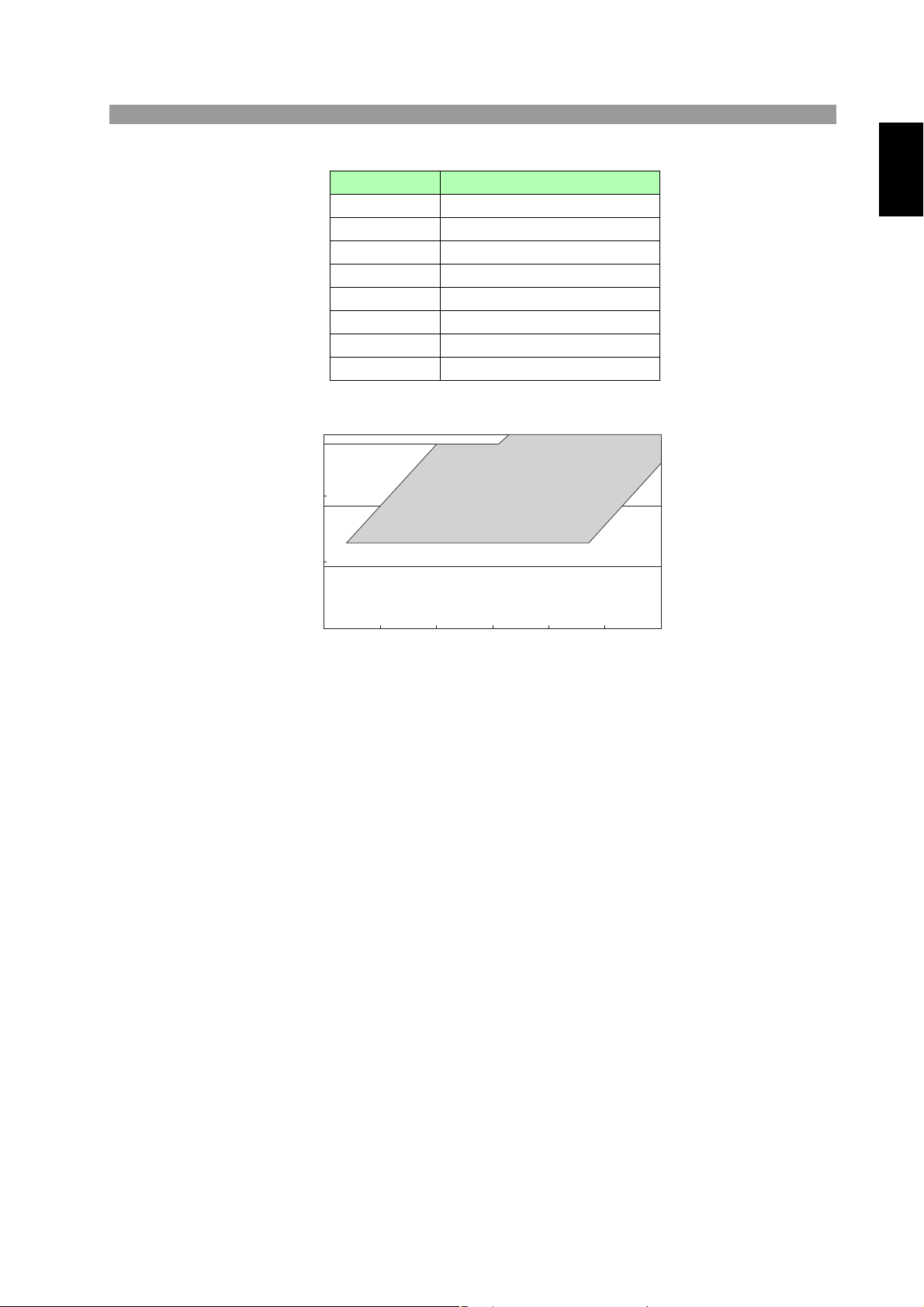
1.2 Features
DCW Output Voltage Range
0.00
2.00
4.00
6.00
8.00
10.0
012345
Current [mA]
Voltage [kV]
■ Two testing functions – DC withstanding voltage, and
insulation resistance tests
When connected to a DUT, the tester can perform these two different tests consecutively.
■ DC withstanding voltage test at 10 kV
(maximum output of 50 W)
The tester can perform DC withstanding voltage tests for a wide voltage range of up
to 10 kV (maximum output of 50 W and maximum duration of 1 minute). The tester
is equipped with a stable, low-ripple DC/DC converter with a voltage regulation of 1
% or less.
■ Improved measurement accuracy
The tester is equipped with a digital voltmeter for withstanding voltage testing with
an accuracy of ±(1 % of the reading +20 V), and another for insulation resistance
testing with an accuracy of ±(1 % of the reading +1 V). The two voltmeters display
measured values not only during a test but also during execution of a program.
The tester is equipped with an ammeter for withstanding voltage testing that features
accuracy of ±(3 % of the reading +5 μA
olution tests, such as those that are required for PV panels. The two ammeters display
measured values not only during a test but also during execution of a program.
■ Insulation resistance test at 25 V to 1500 V (resolution of 1 V) /
0.01 MΩ to 9.99 GΩ (at rated current range of 50 nA to 1 mA
maximum *2)
*1
). Thus, it is capable of performing high-res-
*1: 0 to 2mA range
TOS9213S allows you to conduct an insulation resistance test at test voltage
range of 25 V to 1000 V (resolution of 1 V) with resistance measuring range of
0.01 MΩ to 9.99 GΩ. Whereas, TOS9213AS allows you to conduct a test at
test voltage range of 25 V to 1500 V (resolution of 1 V) with resistance measuring range of 0.01 MΩ to 9.99 GΩ.
*2: For TOS9213AS, if the test voltage setting exceeds 1020 V, the resistance
measuring range is valid at rated current range of 50 nA to 0.1 mA.
1-4 TOS9213S/ TOS9213AS
Test voltage Resistance measuring range
1
10
100
1000
0.01 0.1 1 10 100 1000 10000
Voltage [V]
IR Measurement Range
25 V 0.03 MΩ - 500 MΩ
50 V 0.05 MΩ - 1.00 GΩ
100 V 0.10 MΩ - 2.00 GΩ
125 V 0.13 MΩ - 2.50 GΩ
250 V 0.25 MΩ - 5.00 GΩ
500 V 0.50 MΩ - 9.99 GΩ
1000 V 1.00 MΩ - 9.99 GΩ
1500 V 15.00 MΩ - 9.99 GΩ
Chap. 1
Preface
■ Leakage current judgement (insulation resistance testing)
For insulation resistance testing, in addition to the conventional judgement method
using resistance values, the tester can also perform judgements using the value of
the leakage current that flows through the insulation resistance.
■ Fully programmable GPIB and RS-232C interfaces as a
All functions except for the POWER switch, KEYLOCK, and program execute
(AUTO) functions, are remote-controllable. Test conditions such as the test voltage,
judgement value, and test time can be controlled remotely in DC withstanding voltage and insulation resistance tests. Measured values and measurement results can
also be read back by remote control. The GPIB and RS-232C interfaces provided as
a standard feature smoothly interface the tester with a PC, sequencer, and other
devices.
■ Flexible control function realized by a high-voltage scanner
When combined with the optional high-voltage scanner TOS9220 (5 kVAC/6
kVDC), the tester can test multiple points in withstanding voltage and insulation
resistance tests. Using the tester panel, each channel can be set to a HI/LO/OPEN
voltage. One scanner can operate up to four channels. Up to four scanners can be
connected to the tester, enabling the simultaneous operation of a total of 16 channels. The TOS9221 is equipped with a function for detecting connections between
the high-voltage test leadwire and the DUT, thus ensuring highly reliable testing.
standard feature
TOS9213S/ TOS9213AS 1-5

■ Rise-time control function
In DC withstanding voltage testing, and insulation resistance testing, a voltage can
be slowly increased until it reaches a required test value, instead of applying the
required test voltage to the DUT immediately after the start of a test. The voltage
rise time can be set to 0.1 s through 99.9 s at a resolution of 0.1 s, and to 100 s
through 200 s at a resolution of 1 s. The start voltage, which is applied at the start of
a test, can be set to 0 % to 99 % of the test voltage at a resolution of 1 %. Thus, the
tester conforms to the requirement for the type certification test under the UL standard and the withstanding voltage test under the IEC standard that less than half of
the test voltage be applied initially and slowly increased for a specified period of
time before the test voltage is reached.
■ Discharge function
Generally, DUTs contain capacitive elements. Therefore, DUTs remain charged
immediately after a DC withstanding voltage test or insulation resistance test has
been conducted, resulting in the danger of electric shock. The tester has a function
for forcibly discharging the DUT upon completion of DC withstanding voltage test
or insulation resistance test. You can set the discharge time to a value between 0 and
300 s.
■ Enhanced safety
To enhance safety, the tester is equipped with a number of devices and safety functions, including safe output terminals, a discharge function, and an analog voltmeter
that constantly monitor the output-terminal voltages. Such safety measures also
include a danger lamp that constantly monitors output-terminal voltages even when
no test is under way and lights up when a voltage is detected, in addition to an interlock function that cuts off output in coordination with an external device.
■ Voltage hold function
During judgement, this function allows the tester to retain measured voltages
recorded upon completion of a test, while it is still outputting the judgement results.
Combined with the rise-time control function, the voltage hold function enables
detection of the dielectric breakdown voltage.
■ Output voltage monitoring function
When the output voltage deviates from ± (10 % of the setting +50 V), the monitor-
ing function activates to suspend the test, ensuring highly reliable testing.
■ High operability
The tester is easy to operate, allowing the operator to start using it without difficulty.
The tester displays the primary test conditions on the first page of the menu, with
the secondary test conditions shown on the following pages. To set test conditions,
simply use the cursor key to choose from among the items displayed on the LCD,
and then turn the rotary knob. The function keys allow you to jump to items to be
set. During a test, the output voltage can be changed using the rotary knob.
1-6 TOS9213S/ TOS9213AS
■ Saving 100 test conditions for each test
WARNING
One hundred test conditions, such as the test voltage, judgement value, and test
time, can be set and named for each test of the DC withstanding voltage, and insulation resistance. For example, the name of the applicable safety standard and the
shipment destination of the DUT can be saved. Even when a change is made to the
destination of a product or the name of the applicable safety standard, there is no
need to change the preset test conditions. To recall these test conditions, simply set
the memory number. If such test conditions have their own name, they can be confirmed using that name. Test conditions can even be recalled from outside.
■ Programmed test conditions
By configuring the test conditions saved for each test, 100 test steps can be performed consecutively.
When used together with the earth continuity tester TOS6200, the tester integrates
the test conditions saved in the earth continuity tester to perform continuous tests.
Tests can be performed easily, such as on the insulation resistance, DC withstanding
voltage, and earth continuity, in that order.
Up to 500 steps can be configured, with 100 programs storable, permitting recalls
even from outside.
■ Remote-control function and signal output function
Used exclusively for options, the DIN connector on the front panel enables the
remote control of start/stop operations, like its conventional counterpart. Using the
SIGNAL I/O connector on the rear panel, start/stop operations can be conducted and
the panel memory or program memory can be recalled.
Seven signals are output by the open collector through the SIGNAL I/O connector –
HV ON, TEST, PASS, UPPER FAIL, LOWER FAIL, READY, and PROTECTION.
These signals can be used together with the remote-control function to automate
testing and save labor.
Chap. 1
Preface
• This tester handles a high voltage of 10 kVDC. Therefore, do not touch the
DUT or cables, as electric shock may result.
Around the DUT, provide full safety measures such as an enclosure to
keep workers away. In addition, to ensure safety, exercise extreme care to
prevent the output of a high voltage due to improper connections and operations.
TOS9213S/ TOS9213AS 1-7
1.3 Options
The following options are available for this tester:
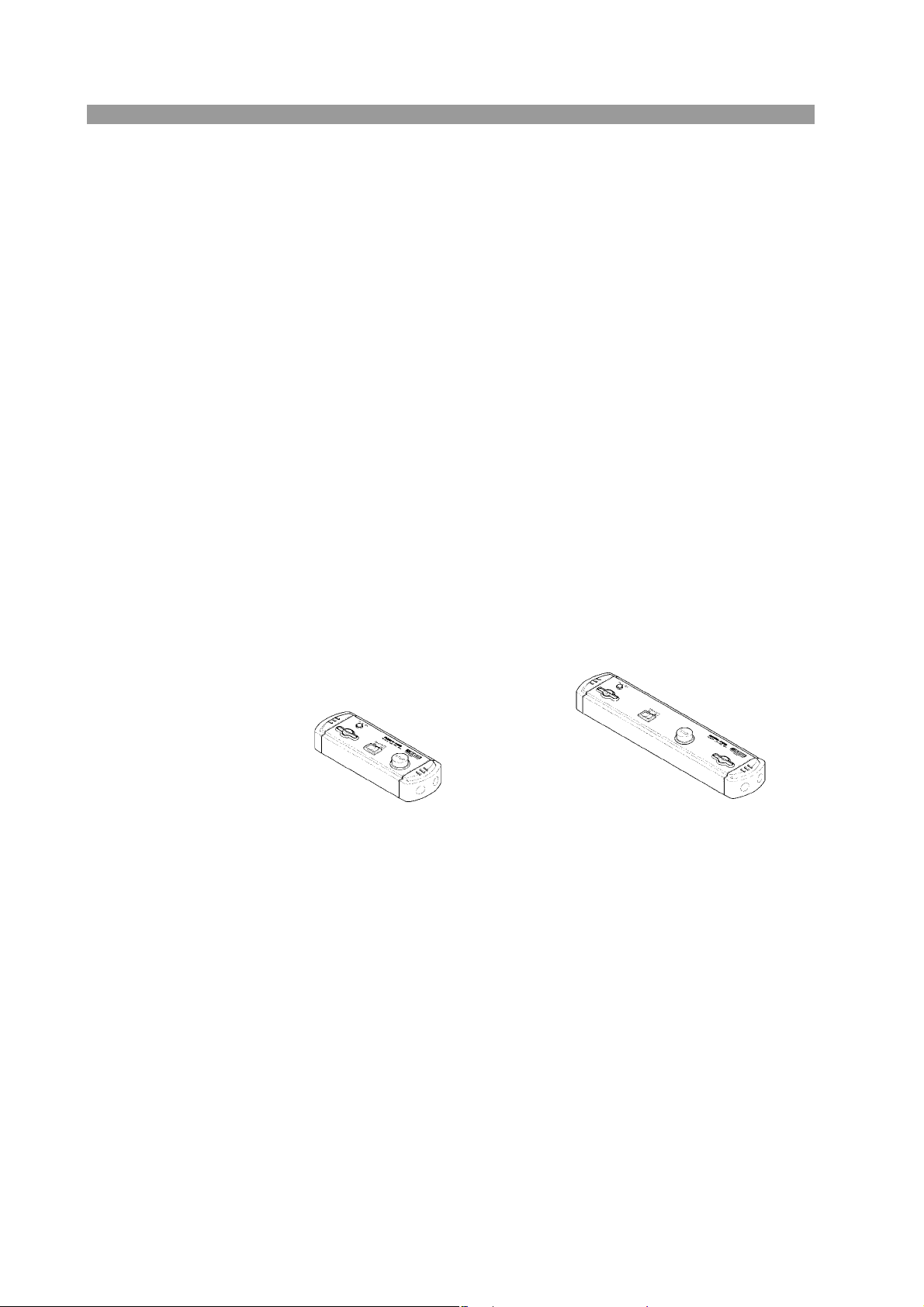
■ RC01-TOS/RC02-TOS remote-control box
This remote-control box is used for remote control of the start/stop operations of
this tester. It is connected to the REMOTE terminal on the front panel.
The RC01-TOS has one START switch. The RC02-TOS has two START switches,
and starts operation only when both are pressed simultaneously.
Function
OPERATE switch
The TEST-switch operation is effective only when the OPERATE switch is on.
Operation is forcibly stopped when the switch is turned off.
START switch
This switch starts a test only when the OPERATE switch is on and in the ready
status.
STOP switch
This switch is used to cut off the output voltage and cancel the FAIL status.
It performs the same function as the STOP switch on the front panel.
RC01-TOS:
200 mm(W) x 70 mm(H) x 39 mm(D)
1-8 TOS9213S/ TOS9213AS
RC02-TOS:
330 mm(W) x 70 mm(H) x 39 mm(D)
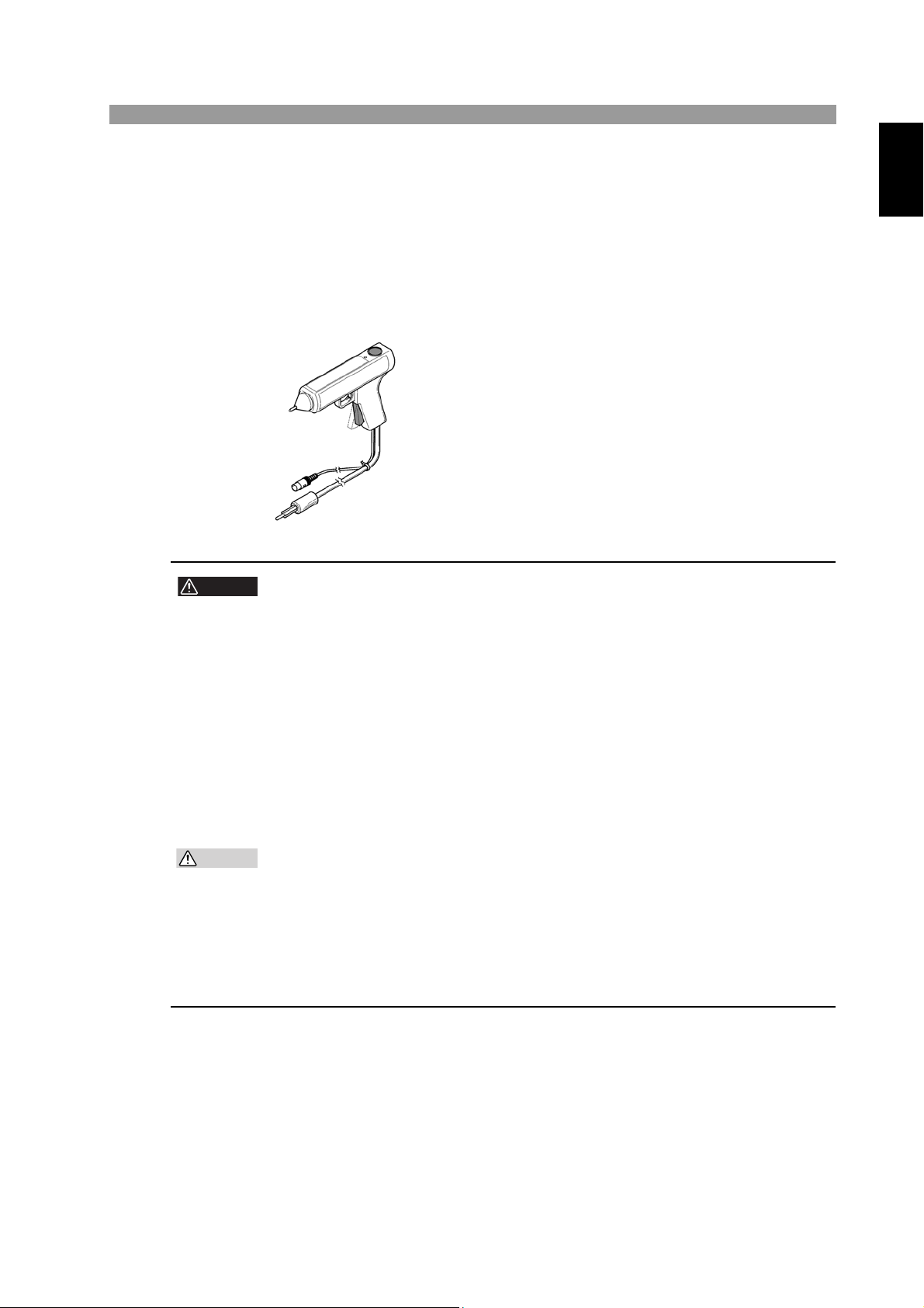
■ High-voltage test probe HP01A-TOS/HP02A-TOS
WARNING
CAUTION
This test probe is connected to Kikusui’s withstanding voltage tester to output a test
voltage. It is designed to prevent the unintended output of a test voltage.
To output a test voltage, hold the slide lever on the test-probe grip and pull the trigger with one hand, then press the switch on top of the probe using the other hand.
When you release either hand, the STOP signal is output and the test voltage is cut
off.
Maximum working voltage
4 kVAC (rms) 50 Hz/60 Hz
5 kVDC
Cable length
HP01A-TOS: Approximately 1.8 m
HP02A-TOS: Approximately 3.5 m
• This probe is designed for a maximum working voltage of 4 kVAC/5 kVDC.
It is dangerous to apply a voltage exceeding this level. Be sure to use this
probe at a test voltage below the maximum working voltage.
• Do not connect this probe to the DUT when a test voltage is being output
from the probe. In addition, do not cut off the connection to the DUT when
a test voltage is being output from the probe.
If the connection between the probe and the DUT is cut off while a high
voltage is being output from the probe, the DUT may be damaged. In addition, the DUT remains charged, making it extremely dangerous.
Therefore, connect the probe to a DUT before staring a test, be sure to
confirm that th
e LED on the probe is off before ending a test, and then dis-
connect the DUT from the probe.
Chap. 1
Preface
• To conduct a test under the UL standard using this probe, turn on the FAIL
MODE function on the tester. When this function is on, the tester performs
the next action to allow the FAIL status to be checked.
When the test ends in the FAIL status, the status is not cancelled even
when you release your hand from the probe. To cancel the FAIL status,
press the STOP switch on the tester. For settings, see “FAIL MODE” in "5.8
System Settings".
TOS9213S/ TOS9213AS 1-9
■ High-voltage scanner
WARNING
The high-voltage scanner TOS9220/TOS9221 has a function to distribute a test voltage supplied by the tester among multiple test points.
• A single high-voltage scanner distributes an output to four channels. Each
channel can be set to a different electric-potential level – HIGH, LOW, or
OPEN. AC/DC testing and insulation resistance testing can be conducted at
any of four test points.
• Up to four scanners can be connected to one tester, enabling expansion to a
maximum of 16 channels.
• The contact between the output on each channel and a test point can be
checked (the contact check function is provided for the TOS9221 scanner
only).
These features ensure highly reliable, labor-saving withstanding voltage and insulation resistance tests on electric and electronic devices and components having multiple test points.
Maximum working voltage
5 kVAC (rms)
6 kVDC
• This high-voltage scanner is designed for a maximum working voltage of 5
kVAC/6 kVDC. It is dangerous to apply a voltage exceeding this level. Be
sure to use this scanner at a test voltage below the maximum working volt-
age.
1-10 TOS9213S/ TOS9213AS

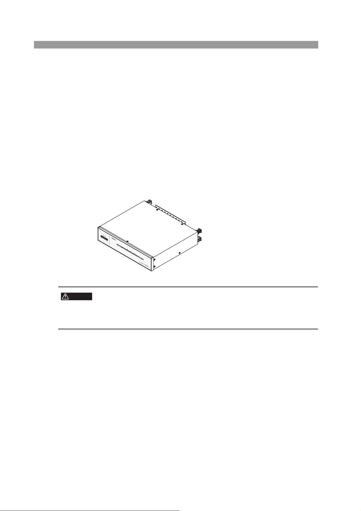
Chapter 2 Setup
This chapter describes the procedures from unpacking to installation to operation
checking.
Chap. 2
Setup
TOS9213S/ TOS9213AS 2-1
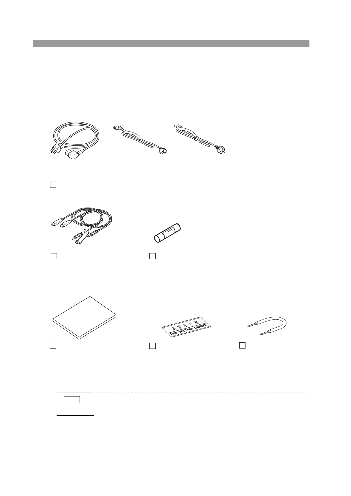
2.1 Unpacking
The power cord that is
provided varies depending
on the destination for the
product at the
factory-shipment.
The fuse that is provided varies
depending on the destination for
the product at the
factory-shipment.
AC Power cord (1 pc.)
TL01-TOS High-voltage
test leadwires (1 set)
1.5 m
[82970]
"HIGH VOLTAGE DANGER"
sticker (1 sheet)
[A8-210-202]
Interlock jumper (1 pc.)
[91-82-1511]
Spare fuse (1 pc.)
10 A, 250 V [99-02-0031]
or 6.3 A, 250 V [99-02-0019]
Operation Manual (1 copy)
[Z1-004-642]
PLUG: NEMA5-15
[85-AA-0003]
PLUG: CEE7/7
[85-10-1070]
or
PLUG: GB1002
[85-10-0790]
or
NOTE
Upon receiving the product, confirm that the necessary accessories are included and
have not been damaged in transit. Should any damage or shortage be found, please
contact Kikusui distributor/agent.
Retain the packing material for future transport.
• Place the "HIGH VOLTAGE DANGER" sticker in a visible location near the tester or installation site.
The product does not include a SIGNAL I/O cable, GPIB interface cable, or RS232C interface cable. Users are requested to procure them on their own.
Fig.2-1 List of accessories
2-2 TOS9213S/ TOS9213AS

2.2 Precautions for Installation
Be sure to observe the following precautions when installing the tester.
■ Do not use the tester in a flammable atmosphere.
To prevent explosion or fire, do not use the tester near alcohol, thinner, or other
combustible materials, or in an atmosphere containing such vapors.
■ Avoid locations where the tester is exposed to high
temperatures or direct sunlight.
Do not locate the tester near a heater or in areas subject to drastic temperature
changes.
Operating temperature range: +5 °C to +35 °C (+41 °F to +95 °F)
Storage temperature range: -20 °C to +70 °C (-4 °F to +158 °F)
■ Avoid humid environments.
Do not locate the tester in a high-humidity environment—near a boiler, humidifier,
or water supply.
Operating humidity range: 20 % to 80 % rh
(no dew condensation permitted)
Storage humidity range: 90 % rh or less
(no dew condensation permitted)
Condensation may occur even within the operating humidity range. In that case, do
not start using the tester until the location is completely dry.
■ Do not place the tester in a corrosive atmosphere.
Chap. 2
Setup
Do not install the tester in a corrosive atmosphere or one containing sulfuric acid
mist or the like. This may cause corrosion of various conductors and imperfect contact with connectors, leading to malfunction and failure, or in the worst case, a fire.
■ Do not locate the tester in a dusty environment.
Dirt and dust in the tester may cause electrical shock or fire.
■ Do not use the tester where ventilation is poor.
This tester features a forced-air cooling system. Provide sufficient space for the air
inlet on the lateral side and the air outlet on the rear side to allow air to flow.
■ Do not place the tester on a tilted surface or in a location
subject to vibrations.
If placed on a non-level surface or in a location subject to vibration, the tester may
fall, resulting in damage and injury.
■ Do not use the tester in locations affected by strong magnetic
or electric fields.
Operation in a location subject to magnetic or electric fields may cause the tester to
malfunction, resulting in electrical shock or fire.
TOS9213S/ TOS9213AS 2-3

■ Do not use the tester in locations near a sensitive measuring
instrument or receiver.
Operation in a location subject, may cause such equipment may be affected by noise generated by the tester.
ated to produce substantial amounts of RF broadband emissions between grips on
the test leadwire. To minimize this effect, secure a sufficient distance between alligator clips.
In addition, keep the alligator clips and test leadwire away from the surfaces of conductors (particularly sharp metal ends).
At a test voltage exceeding 3 kV, corona discharge may be gener-
■ Use the product in an industrial environment.
This product may cause interference if used in residential areas. Such use must be
avoided unless the user takes special measures to reduce electromagnetic emissions
to prevent interference to the reception of radio and television broadcasts.
2.3 Precautions for Moving
When moving the tester to the installation site or otherwise transporting it, take the
following precautions:
■ Before moving the tester, turn off the power switch.
Transporting the tester with its POWER switch on can lead to electric shock and
damage.
■ When moving the tester, Disconnect all wires from it.
Moving the tester without disconnecting the cables may result in breakage of the
wire or injury due to the tester tipping over.
■ For transportation, use the special packing material for the
tester.
Transport the tester in its original package to prevent vibration and falls, which may
damage the tester. If you require packing material, contact Kikusui distributor/agent.
■ Be sure to include this manual.
2-4 TOS9213S/ TOS9213AS
2.4 Checking the Line Voltage and Fuse
CAUTION
Before turning on the POWER switch, be sure to check ratings of the AC power line
and fuse.
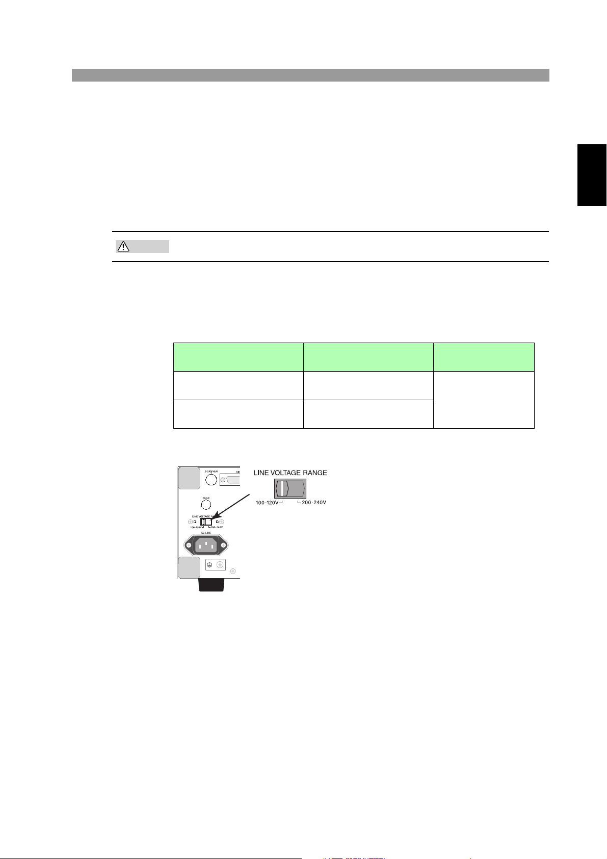
2.4.1 Switching source voltages
• To prevent malfunctions, be sure to operate within the line-voltage range.
The input rating of the tester is shown in Table 2-1. You can change the input voltage with the LINE VOLTAGE RANGE switch on the rear panel. Set the LINE
VOLTAGE RANGE switch for the AC power line that you will use.
Table2-1 Input rating
LINE VOLTAGE RANGE
switch setting
100 - 120 V
200 - 240 V
Nominal voltage range
(Allowable voltage range)
100 VAC to 120 VAC
(85 VAC to 132 VAC)
200 VAC to 240 VAC
(170 VAC to 250 VAC)
Chap. 2
Setup
Allowable frequency
range
47 Hz to 63 Hz
Fig.2-2 LINE-VOLTAGE RANGE switch
TOS9213S/ TOS9213AS 2-5
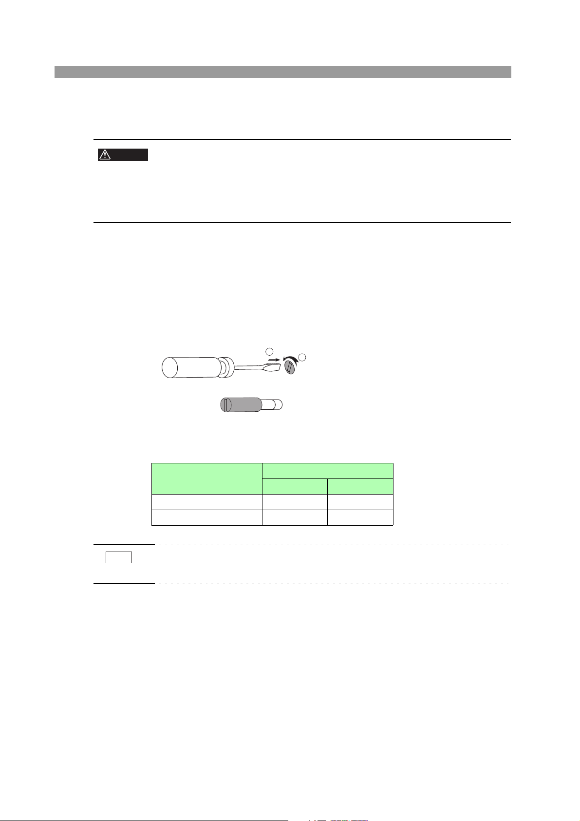
2.4.2 Checking and replacing fuses
WARNING
NOTE
• To prevent electric shock, before checking or replacing the fuse, be sure to
turn off the POWER switch and unplug the AC power cord.
•Make sure that the fuse used conforms to the instrument specifications,
including shape, rating, and characteristics. Using a fuse with different rating or short-circuiting, the fuse holder will damage the instrument.
1. Turn off the POWER switch, and unplug the AC power cord.
2. On the rear panel, remove the fuse holder, as shown in Fig. 2-3, by
pushing it inward and unscrewing it counterclockwise using a screwdriver.
3. In accordance with the fuse rating as shown in Table 2-2, check the fuse
type and replace the fuse.
4. Following the above steps in the reverse order, reinstall the fuse holder.
1
2
Fig.2-3 Removing the fuse holder
Ta ble2-2 Fuse rating
LINE VOLTAGE
RANGE switch setting
100 - 120 V 10 A SLOW –
200 - 240 V – 6.3 A(T)
FUSE (250 V)
UL198G IEC60127
• The pre-arcing time-current characteristic of fuses are named differently in the UL
and IEC standards. Use fuses conforming to both or either of the standards.
2-6 TOS9213S/ TOS9213AS
 Loading...