

www.kikusui.co.jp
ELECTRICAL SAFETY TESTERS
Withstanding Voltage and Insulation Resistance Testers
Withstanding Voltage Testers
Insulation Resistance Testers
Earth Continuity Testers
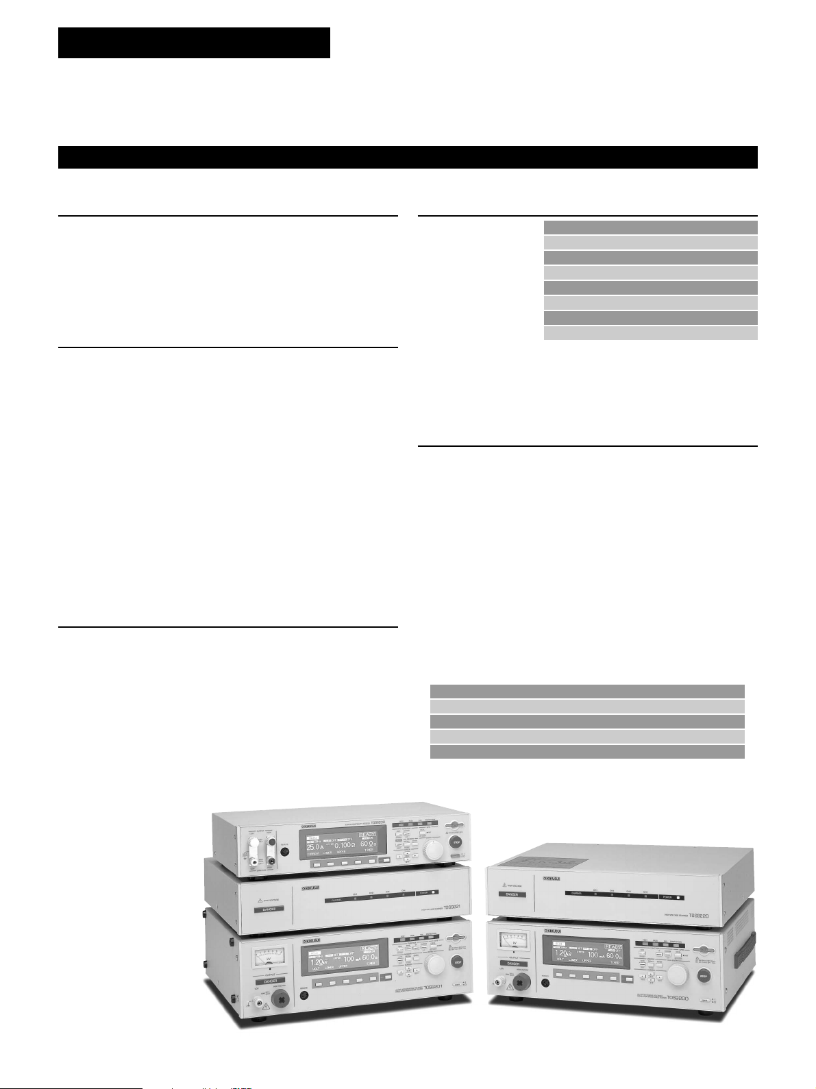
TOS9200 SERIES
TOS SERIES
ELECTRICAL SAFETY TESTER
ELECTRICAL SAFETY TESTERS LINEUP
TOS9201
AC/DC WITHSTANDING VOLTAGE AND
INSULATION RESISTANCE TESTER
TOS9220
HIGH-VOLTAGE SCANNER
TOS9200
AC WITHSTANDING VOLTAGE AND
INSULATION RESISTANCE TESTER
TOS8870A
AC WITHSTANDING VOLTAGE AND
INSULATION RESISTANCE TESTER
TOS9221
HIGH-VOLTAGE SCANNER
(CONTACT CHECK FUNCTION)
TOS5101
AC/DC WITHSTANDING VOLTAGE TESTER
*
TOS5051
AC/DC WITHSTANDING VOLTAGE TESTER
TOS5052
AC WITHSTANDING VOLTAGE TESTER
(RISE-TIME CONTROL FUNCTION)
TOS5050
AC WITHSTANDING VOLTAGE TESTER
*
TOS7200
INSULATION RESISTANCE TESTER
*
TOS5030
AC WITHSTANDING VOLTAGE TESTER
*
TOS6200
EARTH CONTINUITY TESTER
*
2
ELECTRICAL SAFETY TESTERS
The Electrical Appliance & Material Safety Low (Japan),
UL (U.S.A.), CSA (Canada), VDE (Ger many) and BS
(U.K) are some major examples of safety standards in
use throughout the world that require the performing of
withstanding voltage testing. For this reason, it is
necessary to confirm for what portion of what standard
testing is to be performed when purchasing a
withstanding voltage tester . Although the 500 V A capacity
withstanding voltage testers av ailable from KIKUSUI can
basically be applied to tests specified in all safety
standards, we recommend that you consult with us prior
to purchase in order to select the model that best
matches your specific application.
CONTENTS
ELECTRICAL SAFETY TESTERS QUICK REFERENCE P4 to 5
NOTE: Marking
Products equipped with these interfaces as standard.
Products adapted to either VisualBasic, LabVIEW
and LabWindows / CVI.
Refer to the down load service for drivers at
Kikusui Web site.
CE marked products
*
WITHSTANDING VOLTAGE AND INSULATION
RESISTANCE TESTER / TOS9200 SERIES
WITHSTANDING VOLTAGE AND INSULATION
RESIST ANCE TESTER / TOS8870A
WITHSTANDING VOLTAGE TESTER / TOS5000 SERIES
WITHSTANDING VOLTAGE TESTER / TOS5052 P24 to 25
INSULATION RESISTANCE TESTER / TOS7200 P26 to 28
EARTH CONTINUITY TESTER / TOS6200 P29 to 30
P6 to 16
P17 to 19
P20 to 23
These products are limited to available for CE marking model in the specific input voltage, please contact
our local distributor for further detailed information.
OPTION P31 to 32
3
3
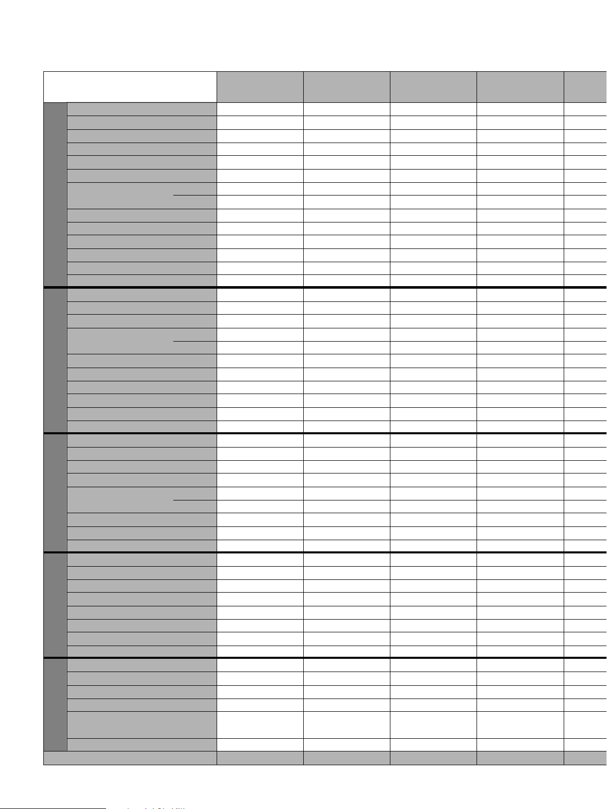
ELECTRICAL SAFETY TESTERS QUICK REFERENCE
Withstanding Voltage and Withstanding Voltage and Withstanding V oltage and
Insulation Resistance tester Insulation Resistance teste Insulation Resistance teste
Item
TOS9201 TOS9200 TOS8870A TOS5101
Output-voltage Range 0.05kV to 5.00kV 0.05kV to 5.00kV
0 to 2.5kV/0 to 5.0kV (two ranges)
Withstanding Voltage Tester
0 to 5kV/0 to 10kV (two ranges)
Output-voltage Resolution 10V 10V - Output-voltage Accuracy
±(1.5 % of setting + 20 V) ±(1.5 % of setting + 20 V)
-Maximum rated load 500VA 500VA 500VA 500VA
Output-voltage Waveform Sine wave Sine wave AC line waveform AC line waveform
Frequency 50Hz/60Hz 50Hz/60Hz AC line frequency AC line frequency
Output Voltmeter Accuracy
Digital
Analog ±5%fs ±5%fs
±(1.0% of reading+30V) ±(1.0% of reading+30V)
Current Measurement Range 0.00mA to 110mA 0.00mA to 110mA
Current Measurement Accuracy
Current Judgement Accuracy
Setting Range for the Test Time 0.3s to 999s 0.3s to 999s 0.5s to 999s
AC Withstanding Voltage test mode
Acceptance Determination by the Window Comparator Method
±(3% of reading+20µA) ±(3% of reading+20µA)
±(3% of setting+20µA) ±(3% of setting+20µA)
✔✔✔✔
±1.5%fs (with limited conditions)
- ±1.5%fs
0.5mA to 100mA (seven ranges)
-
±5% of upper limit
0.2s to 99.9s(X0.1 range)
1s to 999s(X1 range)
0.1mA to 55mA
±(5% of upper limit+20µA)
±(5% of upper limit+20µA)
±5%fs
Rise-Time Control Function ✔✔ --
Output-voltage Range 0.05kV to 6.00kV - -
0 to 5kV/0 to 10kV (two ranges)
Output-voltage Resolution 10V - - Output-voltage Accuracy
Output Voltmeter Accuracy
Digital
Analog ±5%fs - - ±5%fs
±(1.5 % of setting + 20 V)
±(1.0 % of setting + 30 V)
---
--±1.5%fs
Current Measurement Range 0.00mA to 11mA - - 0.1mA to 5.5mA
Current Measurement Accuracy
Current Judgement Accuracy
±(3% of reading+20µA)
±(3% of setting+20µA)
--
--
±(5% of upper limit+20µA)
±(5% of upper limit+20µA)
Setting Range for the Test Time 0.3s to 999s - - 0.5s to 999s
Acceptance Determination by the Window Comparator Method
DC Withstanding Voltage test mode
Rise-Time Control Function ✔ ---
Output-voltage Range -25V to -1000V DC -25V to -1000V DC
✔ --✔
-500V/-1000V DC (two ranges)
Output-voltage Resolution 1V 1V - Output-voltage Accuracy
±(1.5 % of setting + 2 V) ±(1.5 % of setting + 2 V)
--
Maximum Rated Load 1mA 1mA - -
Output Voltmeter Accuracy
Digital ±(1% of reading + 1 V) ±(1% of reading + 1 V) - -
Resistance Meter Measurement Range 0.01MΩ to 9.99GΩ 0.01MΩ to 9.99GΩ -
Setting Range for the Test Time 0.5s to 999s 0.5s to 999s -
Insulation Resistance test mode
Acceptance Determination by the Window Comparator Method
Analog ±5%fs ±5%fs - -
1 to 1000MΩ(500V ranges)
2 to 2000MΩ(1000V ranges)
0.5s to 99.9s(X0.1 range)
1s to 999s(X1 range)
✔✔✔ Output Current Setting Range - - - Output Current Setting Resolution - - - Output Ammeter Accuracy - - - Output Voltmeter Accuracy - - - Output Frequency - - - Ohmmeter Measurement Range - - - Ohmmeter Measurement Resolution - - - -
Earth Continuity test mode
Setting Range for the Test Time - - - External Remote I/F GPIB/RS-232C GPIB/RS-232C - Readback of the measured data to the external
GPIB/RS-232C GPIB/RS-232C - Memory Function ✔✔ --
Multi Channels Capability
Others
Power Nominal Voltage Range
CE Marking ✔✔✔
High Voltage Scanner Unit High Voltage Scanner Unit
100V to 120V AC/200V to 240V AC 100V to 120V AC/200V to 240V AC
Selectable Selectable
--
100V±10% 100V±10%
Can be Factory-modified to nominal
110V, 120V, 220V, 230V and 240V
Can be Factory-modified to nominal
110V, 120V, 220V, 230V and 240V
230V AC Input model only
Reference page 6 to 16 6 to 16 17 to 19 20, 23
4
Withstanding Voltage Tester Withstanding Voltage Tester Withstanding Voltage Tester Withstanding Voltage T ester Insulation Resistance Tester Earth Continuity Tester
TOS5051 TOS5050 TOS5030 TOS5052 TOS7200 TOS6200
0 to 2.5kV/0 to 5.0kV (two ranges) 0 to 2.5kV/0 to 5.0kV (two ranges)
- - - 10V - -
---
500VA 500VA 30VA 500VA - AC line waveform AC line waveform AC line waveform Sine wave - AC line frequency AC line frequency AC line frequency 50Hz/60Hz - -
±5%fs ±5%fs ±5%fs ±5%fs - -
±1.5%fs ±1.5%fs - ±1.5%fs - -
0.1mA to 110mA 0.1mA to 110mA 0.5/1/2/5/10mA 0.00mA to 110mA - -
±(5% of upper limit+20µA) ±(5% of upper limit+20µA)
±(5% of upper limit+20µA) ±(5% of upper limit+20µA)
0.5s to 999s 0.5s to 999s - 0.3s to 999s - ✔✔ - ✔ --
---✔ --
0 to 2.5kV/0 to 5.0kV (two ranges)
-----
------
------
±5%fs - - - - -
±1.5%fs - - - - -
0.1mA to 11mA - - - - -
±(5% of upper limit+20µA)
±(5% of upper limit+20µA)
-----
-----
0.5s to 999s - - - - ✔ -----
------
- - - - -25V to -1000V DC -
----1V-
----
----1mA-
------
----±(1% of reading + 1 V) -
- - - - 0.01MΩ to 5000MΩ -
- - - - 0.5s to 999s -
----✔ -
- - - - - 3.0 to 30.0A AC
- - - - - 0.1A
-----
-----
- - - - - 50/60Hz
- - - - - 0.001 to 1.200Ω
- - - - - 0.001Ω
- - - - - 0.3s to 999s
- - - - RS-232C GPIB/RS-232C
- - - - RS-232C GPIB/RS-232C
----✔✔
------
100V±10% 100V±10% 100V±10% 100V±10%
Can be Factory-modified to nominal
110V, 120V, 220V, 230V and 240V
Can be Factory-modified to nominal
110V, 120V, 220V, 230V and 240V
230V AC Input model only230V AC Input model only230V AC Input model only 230V AC Input model only
21, 23 21, 23 22, 23 24, 25 26 to 28 29, 30
0 to 3kV
-
±5% of preset cutoff current
Can be Factory-modified to nominal
110V, 120V, 220V, 230V and 240V
0 to 2.5kV/0 to 5.0kV (two ranges)
±(2 % of setting + 2digits) at 0.20kV or higher with no load
±(5% of upper limit+20µA)
±(5% of upper limit+20µA)
Can be Factory-modified to nominal
110V, 120V, 220V, 230V and 240V
--
--
--
--
±(1.5 % of setting + 2 V)
100V to 240V
✔✔
-
±(1 % of reading + 0.2A)
±(1 % of reading + 0.02V)
100V model: 85 to 132V AC
100V/200V model: 85 to 132V AC
170 to 250V AC
5
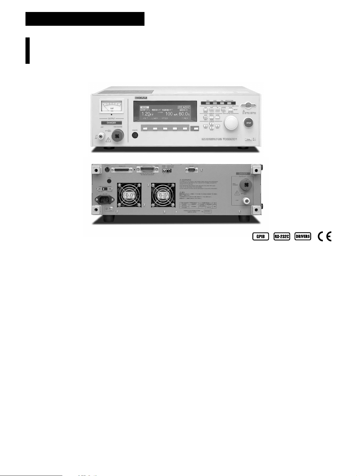
TOS9200 SERIES
Withstanding Voltage and Insulation Resistance Tester
Perfect design for System Operation, introducing our top of the
line of Withstanding Voltage / Insulation Resistance Testers
TOS9201(AC/DC)
TOS9200(AC)
Capable of performing withstanding voltage and insulation
testing in comply with safety standards, including IEC, EN,
VDE, BS, UL,CSA, JIS and the Electrical Application and
Material Safety Law (Japan)
The TOS9200 Series has been developed to meet a wide diversity of
customer needs. Including the refinement and enforcement of Kikusui’s
former series, its specifications reflect the results of detailed study of
our large database of user’s requirements including special orders and
modifying specifications.
The TOS9200 Series consists of four products the testers TOS9200 and
TOS9201, and the high-voltage scanners TOS9221 and TOS9220.
The TOS9200 is equipped with AC withstanding voltage and insulation
resistance testing functions, while the TOS9201 has a DC withstanding
voltage testing function in addition to these two functions. The power
block, a core component, employs a high-efficiency switching power
supply and a switching amplifier based on PWM systems. These features
realize high power and enhanced stability, as well as reducing the size
and weight of the unit. When combined with the earth continuity tester
TOS6200, the TOS9200 Series integrates three or four types of tests in a
single process.
Furthermore, when used together with the high-voltage scanner
TOS9220/9221 (equipped with a contact check function), the tester is
capable of automatically checking test points for up to 16 channels,
thereby facilitating a safe, reliable automatic testing system.
● Rise-time control function
● Fall-time control function
● Offset cancel function
● Measured-value hold function
● Output voltage monitoring function
● Memory function
● Program function
● Interlock Function
● DC Discharge Function
6
TOS9200 SERIES
Withstanding Voltage and Insulation Resistance Tester
Basic performance
Three functions - AC withstanding voltage testing, DC
withstanding voltage testing and insulation resistance testing
The TOS9200 can perform AC withstanding voltage tests and
insulation resistance tests, while the TOS9201 can also conduct
DC withstanding tests. Once connected to a device being tested,
the TOS9201 executes an AC withstanding voltage test, DC
withstanding voltage test, and insulation resistance testing in
succession in one process.
AC withstanding voltage testing at 5 kV and 100 mA
Equipped with a high-efficiency switching power supply in its highvoltage power block, a PWM-based switching amplifier and a 500
VA high-voltage transformer, the TOS9200/TOS9201 realizes a
maximum output of 5 kV/100 mA (continuous output for 30 minutes),
or 2.5 times the output of Kikusui’s former models. At a test voltage
of 500 V or more and an upper current of 100 mA, or greater the
tester instantaneously satisfies the requirements of a short-circuit
current of 200 mA or more which is required by the IEC standard *.
In addition, the tester ensures a load effects of 30% or less and
the generation of a consistent 50 Hz/60 Hz test voltage free from
the affect of the supply voltage. These features eliminate the need
to readjust the output voltage once the test voltage is preset.
*Continuous outputs are impossible because the output is cut off if
an overcurrent is detected.
DC withstanding voltage testing at 6 kV and a maximum output
of 50 W
The TOS9201 permits DC withstanding voltage testing at up to 6
kV *. The tester is equipped with a stable, low-ripple DC/DC
converter with a load factor of 1% or less.
*Maximum output of 50 W for up to 1 minute.
Insulation resistance testing at 25 V to 1000 V and 0.01 MΩ to
9.99 GΩ
The test voltage can
be set to 25 V through
1000 V at a resolution
of 1 V. Insulation
resistance covers a
wide measurement
range from 0.01 MΩ to
9.99 GΩ *.
Test voltage Resistance measurement range
25V 0.03 MΩ to 500 MΩ
50V 0.05 MΩ to 1.00 GΩ
100V 0.10 MΩ to 2.00 GΩ
125V 0.13 MΩ to 2.50 GΩ
250V 0.25 MΩ to 5.00 GΩ
500V 0.50 MΩ to 9.99 GΩ
1000V 1.00 MΩ to 9.99 GΩ
A single unit of the TOS9200/9201 is capable of handling all test
voltages required by JIS C 1302 1994 (Insulation Resistor Meter)
and fully meets the JIS requirements.
*At a maximum rated current of 1 mA to 50 nA.
Enhanced measurement accuracy
The TOS9200/9201 is provided with a digital voltmeter for
withstanding voltage testing at an accuracy of ±(1% of reading +
30 V) and another one for insulation resistance testing at an
accuracy of ±(1% of reading + 1 V). Measured values are displayed
not only during a test, but while a program is being executed. A
digital ammeter with an accuracy of ±(3% of reading + 20 µA) is
also provided for withstanding voltage testing. Kikusui’s
predecessors had a highest measurement resolution of about 1
mA , with an accuracy of ±5% of the upper cutoff current when it is
set to 100 mA. In contrast, the digital ammeter allo ws the T OS9200/
9201 to make measurements at an accuracy of ±(3% of reading +
20 µA), even if the upper current is set to 100 mA. The ammeter
displays measured values while the program executes, as well as
during an AC or DC withstanding voltage test.
Type Display accuracy
Voltmeter for withstanding voltage testing ± (1% of reading + 30V)
Ammeter for withstanding voltage testing ± (3% of reading + 20µA)
Voltmeter for insulation resistance testing ± (1% of reading + 1V)
Insulation resistance meter ± (2% of reading)*
*At 1 µA< measured current ≤ 1 mA
7
TOS9200 SERIES
Withstanding Voltage and Insulation Resistance Tester
Diverse functions
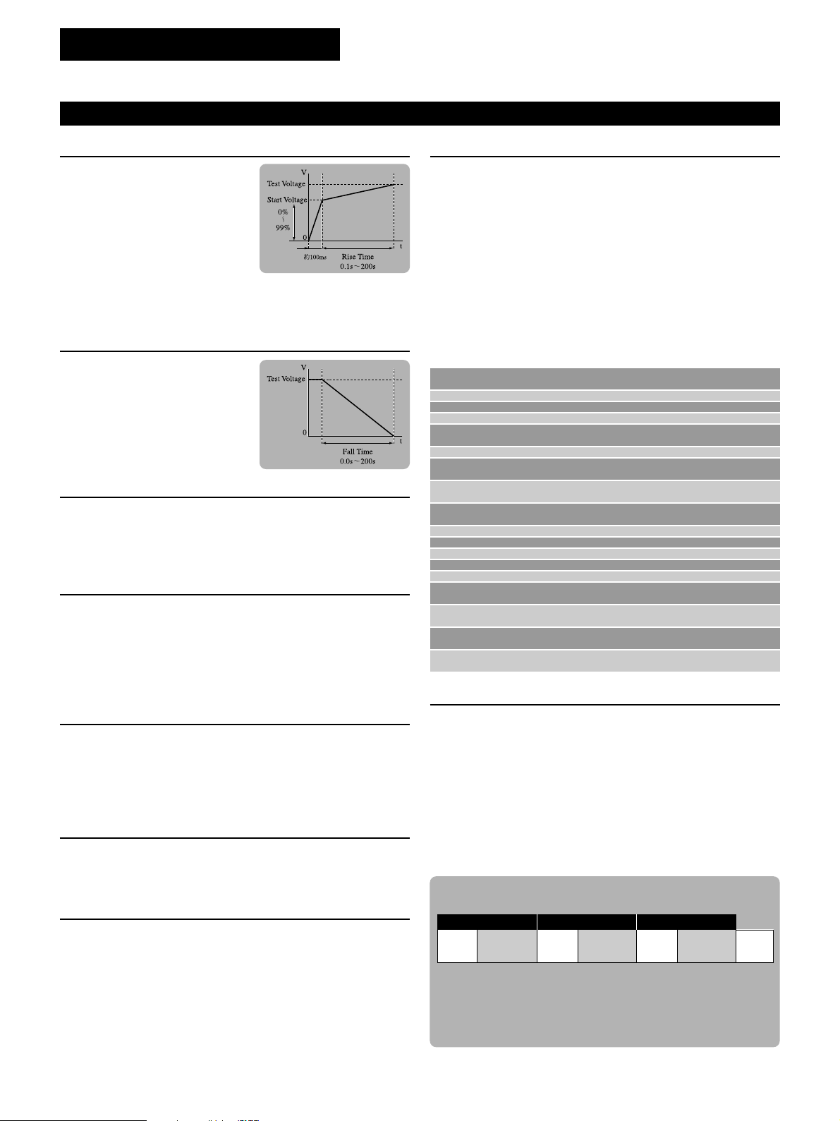
Rise-time control function
In AC withstanding voltage testing, DC
withstanding voltage testing and
insulation resistance testing, you can
apply a voltage gradually to reach the
test voltage, instead of applying the test
voltage directly at the start of a test. The
voltage increase time can be set to 0.1
s through 99.9 s at a resolution of 0.1 s,
and to 100 s to 200 s at a resolution of 1 s. The start voltage is also
adjustable between 0% and 99% at a resolution of 1%.
Fall-time control function
In AC withstanding voltage testing, you
can gradually decrease the test voltage
after a PASS judgment. The v oltage f all
time is adjustable between 0.0 s and
99.9 s at a resolution of 0.1 s, and
between 100 s and 200 s at a resolution
of 1 s.
Offset cancel function
In AC withstanding voltage tests that require high sensitivity and high
voltages, currents flowing into the stray capacity of the test lead wire,
jigs, and other components can cause measurement errors. The
TOS9200/9201 features a function to cancel these offset currents.
Voltage hold function
During measurement, this function allows you to hold the value of the
voltage measured at the end of an AC or DC withstanding voltage test,
as long as the test results are being displayed. When combined with
the rise-time control function, this function enables to observe the
insulation breakdown voltage.
Memory function
Up to 100 test conditions used in AC and DC withstanding voltage
testing and insulation resistance testing, such as the test voltage,
judgment value and test time, can be stored with a specific name. For
instance, you can store the name of an applied safety standard and
the destination of the product to be tested. If test conditions are preset,
operator can recall relevant test conditions simply by entering the
memory number. If y ou pre viously assigned a special name to each of
these test conditions, operator can check recalled test conditions by
name. The memory function allows you to recall test conditions not
only through the recall operation on the front panel, but also by remote
control.
[Storable test conditions]
AC withstanding DC withstanding
Test voltage ✔✔✔
Test frequency ✔
Lower cutoff value ✔✔✔
ON/OFF of the lower
judgment function
Upper cutoff value ✔✔✔
ON/OFF of the upper
judgment function
ON/OFF of the offset
function
Test time and ON/OFF
of the timer function
Start voltage ✔✔
Voltage rise time ✔✔✔
Voltage fall time ✔
Judgment wait time ✔✔
Test voltage range ✔
SLOW/MID/FAST settings
for the response filter
FLOAT/GND of the
LOW terminal
HIGH/LOW/OPEN settings
for the scanner channel
ON/OFF of the contact
check function
voltage testing voltage testing testing
✔✔✔
✔
✔✔✔
✔
✔✔✔
✔✔✔
✔✔✔
Insulation resistance
✔
Maximum Leakage current and minimum resistance hold
function
By selecting “MIN/MAX Mode” in the measurement mode settings, y ou
can hold the maximum current in withstanding voltage testing and the
minimum resistance after the judgment wait time in insulation resistance
testing. These values are shown on the tester’s displa y. They can also
be read back via interface (GPIB or RS-232C).
Output voltage monitoring function
When the output voltage deviates from ±(10% of setting + 50 V), the
monitoring function activates to suspend the test, thus ensuring highly
reliable testing.
Current detection response speed adjustment function
This function switches current detection response speeds for UPPER
judgment by adjusting the integrated time constant of the current
detection circuit. Three modes are available for the integrated time
constant: SLOW (about 40 ms), MID (about 4 ms) and FAST (about
0.4 ms). SLOW mode is used in normal operations. MID and FAST
modes are more effective in detecting a discharge occurring
instantaneously or containing a large number of frequency components.
They are also useful for withstanding voltage tests of test devices that
insulation likely be breakdown, such as small electronic components.
8
Program function
By coordinating test conditions stored in an AC withstanding voltage
test, DC withstanding voltage test, and insulation resistance test,
operator can sequentially run tests that comprise up to 100 steps. When
used together with the earth continuity tester TOS6200, the TOS9200
Series permits continuous tests combining test conditions stored in
the TOS6200, as well as on the TOS9200 itself. Sequential tests are
possible, for e xample, on AC withstanding v oltage, insulation resistance,
DC withstanding voltage, and earth continuity, in order. The TOS9200
Series stores up to 500 steps and 100 programs, which can be recalled
through the recall operation on the front panel or by remote control.
[Sample program]
Step 00 Step 01 Step 02
Memory Interval Memory Interval Memory Interval
ACW01
0.2s DCW01 0.2s IR01 0.2s
END
At Step 00, Step 01 and Step 02, memory ACW01 (AC withstanding
voltage test), DCW (DC withstanding voltage test: TOS9201 only)
and IR01 (insulation resistance test) are performed, receptively, in
succession at 0.2-second intervals.
TOS9200 SERIES
Withstanding Voltage and Insulation Resistance Tester
Interfaces
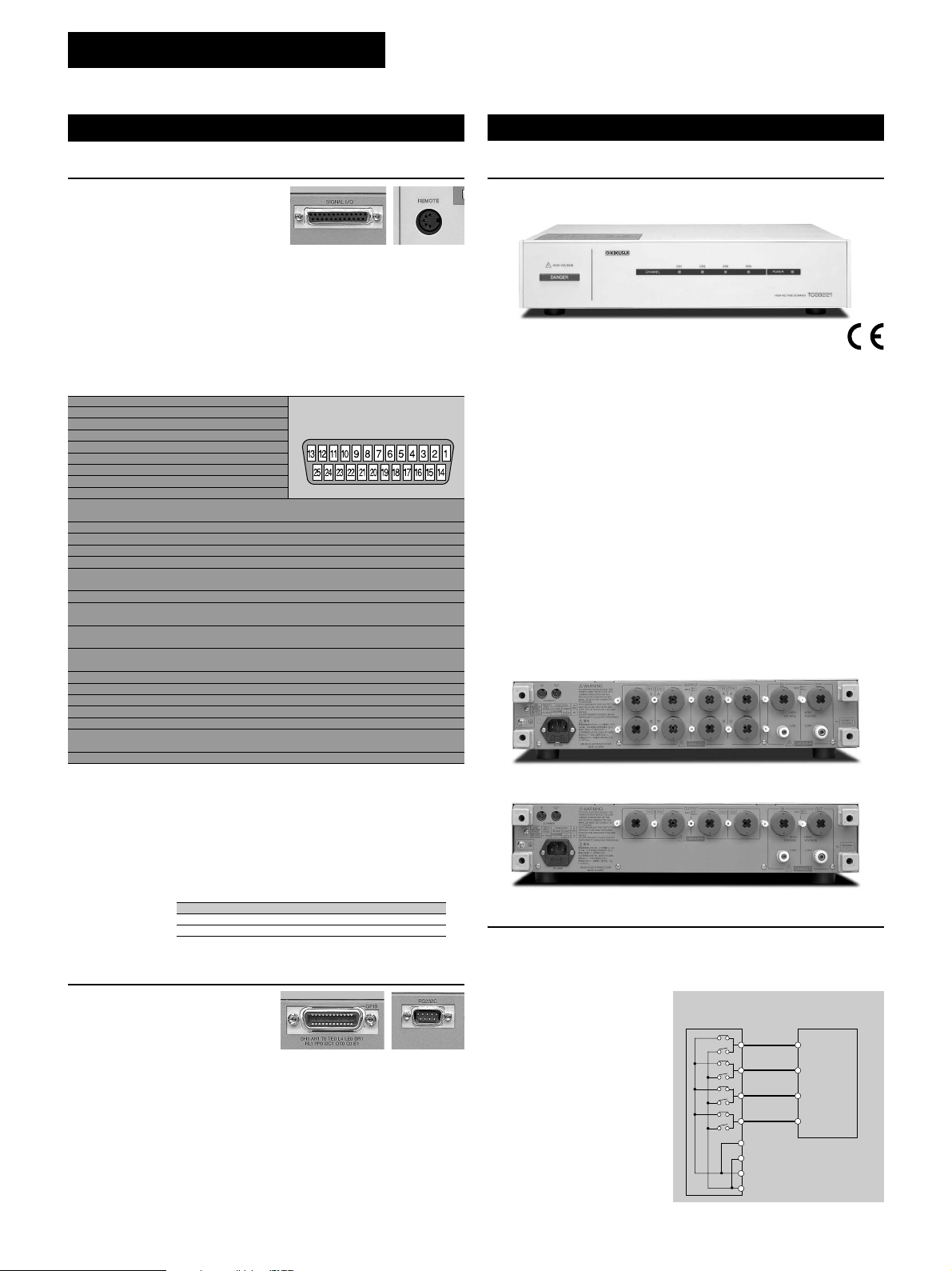
REMOTE connector & SIGNAL I/O connector
The REMOTE connector on the front
panel is intended exclusively for
Kikusui’s options (remote control/test
probe). It allows start and stop
operations by remote control. The SIGNAL I/O connector on the
rear panel permits operator to recall panel memory and program
memory contents by remote control, as well as controlling start
and stop operations. Seven different signals are output from the
SIGNAL I/O connector through the open collector.
[SIGNAL I/O]
No. Signal name I/O Details of signal
1 PM0 I LSB, LSD *1
2 PM1 I LSD *1
3 PM2 I LSD *1
4 PM3 I LSD *1
5 PM4 I MSD *1
6 PM5 I MSD *1
7 PM6 I MSD *1
8 PM7 I MSB, MSD *1
9 STB I Input terminal for the strobe signal of the panel memory and
10 MODE0 I Selects a test mode *2
11 MODE1 I Selects a test mode *2
12 NC
13 COM Circuit common (chassis potential)
14 H.V ON O ON during a test and an automatic test (AUTO) or while a
15 TEST O ON dur ing a test (except for voltage rise and voltage fall)
16 PASS O ON during the time preset in the PASS HOLD settings when a
17 U FAUL O Continuously ON in an UPPER FAIL judgement. Continuously
18 L FAUL O Continuously ON in an LOWER FAIL judgement. Continuously
19 READY O ON during the READY status
20
PROTECTION
21 START I Input terminal for the START signal
22 STOP I Input terminal for the STOP signal
23 ENABLE I Input terminal for the ENABLE signal for the START signal
24 +24V Output terminal for +24 V internal power, with a maximum
25 COM Circuit common (chassis potential)
● Input signal [Low active control input High-level input voltage: 11 V to 15 V /
Low-level input voltage: 0 V to 4 V / Low-level input current: Maximum –5 mA /
Input interval: Minimum 5 ms]
● Output signal [Open collector output Output withstanding voltage: DC 30 V / Output
saturation voltage : Approximately 1.1 V (25 °C) /Maximum output current : 400 mA
(TOTAL)]
* The input signal circuit is pulled up to +12V. Therefore, opening the input terminal is
equivalent to inputting a high-level signal.
*12-digit BCD low active input Signal input terminal for selection between the panel
memory for ACW, DCW, and IR, and the program memory for AUTO Memory recall by
latching this selection signal at the rise of the strobe signal
*22-bit low active input
program memory
voltage remains between the output terminals
PASS judgement is made
ON in a CONTACT FAIL judgement with the scanner connected.
ON in a CONTACT FAIL judgement with the scanner connected.
O ON when the PROTECTION function is activated
output current of 100 mA
Test mode ACW DCW IR AUTO
MODE0 H L H L
MODE1 H H L L
GPIB/RS-232C interface
A GPIB/RS-232C interface is
provided as a standard feature to
facilitate the remote control of all
functions of the TOS9200/9201
except the POWER switch, the KEYLOCK function, and the
program execution (AUTO) function.
RS-232C [Baud rate: 9600/19200/38400 bps/TOS6200 interface (AUTO mode
only): START/STOP control, test condition settings, reading of TOS6200
measured values, and measurement results]
GPIB [Remote control of all functions except the POWER switch, the KEYLOCK
function, and the program execution (AUTO) function/SH1, AH1, T6, TE0, L4,
LE0, SR1, RL1, PP0, DC1, DT0, C0, E1]
[Pin Configuration for the
SIGNAL I/O Connector]
Peripheral devices
High-voltage scanner TOS9220/TOS9221
TOS9221 Front View (same for TOS9220)
TOS9221
TOS9220
The high-voltage scanner TOS9220/TOS9221 has a function that
distributes the test voltage provided by the TOS9200/9201 to
multiple test points. Up to four channels can be used for outputs
on this scanner. Each channel can be set to one of the three
electric potential modes – HIGH, LOW, or OPEN. Operator can
conduct AC/DC withstanding voltage and insulation resistance tests
on any of the four test points. Fur ther more, up to four scanners
can be connected to the tester, allowing a maxim um of 16 channels.
The T OS9200 is equipped with a “contact check function” to check
the contact between the output of each channel and a test point.
These features ensure highly reliable and labor-saving withstanding
voltage and insulation resistance tests for electrical and electronic
equipment with multiple test points.
TOS9221 Rear View
TOS9220 Rear View
Operation of the high-voltage scanner
On the TOS9200/TOS9201, you can select an electric potential
mode for each channel – HIGH (high voltage side), LOW (low
voltage side), and OPEN (open mode). The high-voltage scanner
permits AC/DC withstanding
voltage or insulation resistance
tests on any of the four test
points A to D. For instance, you
can set CH1 (test point A) to
HIGH, CH2 (test point B) to
OPEN, and CH3 (test point C)
CH4 (test point D) to LOW. To
specify these settings, you can
use the TOS9200/9201 panel
or the GPIB/RS-232C.
High-voltage
scanner (TOS9220)
CH1[HIGH]
CH2[OPEN]
CH3[LOW]
CH4[LOW]
OUT HIGH VOLTAGE terminal
OUT LOW terminal
IN HIGH VOLTAGE terminal
N LOW terminal
Device being tested
Test point A
Test point B
Test point C
Test point D
T o T OS9200
}
/9201
9
TOS9200 SERIES
Withstanding Voltage and Insulation Resistance Tester
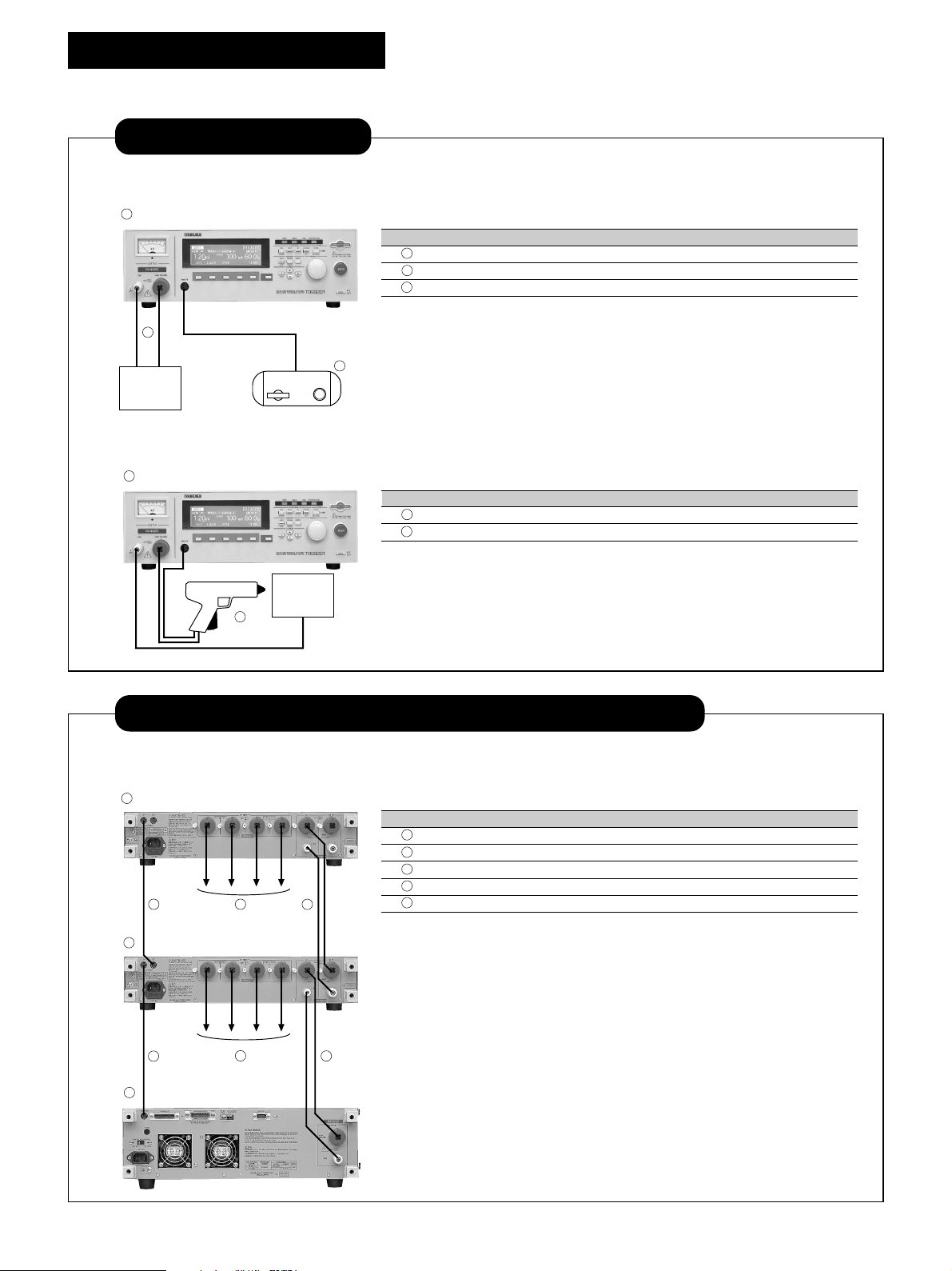
For Stand alone use
...
Example of system for applying voltage by Test Lead or start/stop operation by Remote Control Box.
1
Item Model cable length
1
2
DUT
Withstanding Voltage / Insulation Resistance Tester AC/DC
2 High-V oltage Test Lead TL01-TOS 1.5m *1 1 set
3 Remote Control Box RC01-TOS *2 1.5m 1 pc.
*1: Also available for 3m cable, TL02-TOS
*2: Also available for both-hands operation, RC02-TOS
3
TOS9201 1 pc.
Example of system for applying voltage or start/stop operation by High-Voltage Test Probe.
1
Item Model cable length
1
Withstanding Voltage / Insulation Resistance Tester AC/DC
2 High-V oltage Test Lead HP01A-TOS 1.5m *1 1 pc.
*1: Also available for 3m cable, HP02A-TOS
DUT
2
TOS9201 1 pc.
Reguired numbers
Reguired numbers
For Multiple Channel Testing by High Voltage Scanner
Example of system consisting TOS9201 and TOS9220 ✕ 2sets (8CH)
1
Item Model cable length
1 High-Voltage Scanner TOS9220 2 pc.
2
Withstanding Voltage / Insulation Resistance Tester AC/DC
3 Interface cable 85-50-0210 0.5m *1 2 pc.
4 High-Voltage Test Lead (red) TL07-TOS 1.5m 8 pc.
3 4 5
1
3
2
to DUT
4
to DUT
5
5 High-Voltage Leads for Parallel connection TL06-TOS 0.5m *2 2 set
*1: Also available for 2m cable, DD2M-8P
*2: Also available for 1.5m cable, TL04-TOS
[Rack mount bracket]
TOS9200 / 9201 (JIS) KRB150-TOS
(EIA) KRB3-TOS
TOS9220 / 9221 (JIS) KRB100-TOS
(EIA) KRB2-TOS
[CAUTION] In case of using more than 2sets of High Voltage Scanner, it is required to
rack mount or locate these unit to the side of Withstanding / Insulation Resistance Tester,
And it should not be piled up more than 2sets of High Voltage Scanner units.
...
Reguired numbers
TOS9201 1 pc.
10

TOS9200 SERIES
Withstanding Voltage and Insulation Resistance Tester
Single process to apply until earth continuity test
Example of system consisting TOS9201 and TOS6200
1
Item Model cable length
1 Earth Continuity Tester TOS6200 1 pc.
2
Withstanding V oltage / Insulation Resistance Tester AC/DC
(from front panel)
3
2
4
(from front panel)
5
DUT
3 RS-232C Cross Cable 1 pc.
4 Low-V oltage Test Lead TL11-T OS 1.5m 1 set
5 High-V oltage Test Lead TL01-TOS 1.5m *1 1 set
*
1: Also available for 3m cable, TL02-TOS
[Rack mount bracket]
TOS9200 / 9201 (JIS) KRB150-TOS
(EIA) KRB3-TOS
TOS6200 (JIS) KRB100-TOS
(EIA) KRB2-TOS
...
Reguired numbers
TOS9201 1 pc.
It is capable to perform for withstanding voltage / Insulation Resistance and Earth continuity testing in one single process by controlling
TOS6200 from TOS9201.
Fully Automated System by PC
...
Example of system consisting TOS9201, TOS9200 (4CH) and TOS6200
1
Item Model cable length
1 High-Voltage Scanner TOS9220 1 pc.
2
Withstanding V oltage / Insulation Resistance Tester AC/DC
4
2
3
9
8
5
to DUT
8
Possible to control
TOS9201 and TOS6200
and acquire the test result.
6
(from front panel)
7
to DUT
3 Earth Continuity Tester TOS6200 1 pc.
4 Interface cable 85-50-0210 0.5m *1 1 pc.
5 High-Voltage Test Lead (red) TL07-TOS 1.5m 4 pc.
6 High-Voltage Leads for Parallel connection TL06-TOS 0.5m *2 1 set
7 Low-V oltage Test Lead TL11-T OS 1.5m 1 set
8 GPIB Cable 408J-102 2m *3 2 pc.
9 PC (with GPIB Interface cable) 1 pc.
*1: Also available for 2m cable, DD2M-8P
*2: Also available for 1.5m cable, TL04-TOS
*3: Also available for 1m cable, 408J-101 and 4m cable, 408J-104
[Rack mount bracket]
TOS9200 / 9201 (JIS) KRB150-TOS
TOS9220 / 9221 / 6200
[CAUTION] In casa of use for combining more than 2sets of High Voltage Scanner unit
and Earth Continuity Tester, it is required to rack mount or locate these unit to the side of
Withstanding / Insulation Resistance Tester, And it should not be piled up more than
2sets of High Voltage Scanner units.
(EIA) KRB3-TOS
(JIS) KRB100-TOS
(EIA) KRB2-TOS
Reguired numbers
TOS9201 1 pc.
11

TOS9200 SERIES
Withstanding Voltage and Insulation Resistance Tester
Withstanding Voltage test mode
Item TOS9200 TOS9201
Output section
Output-voltage range 0.05 kV to 5.00 kV
Maximum rated load (*1) 500 VA (5 kV/100 mA)
Maximum rated current 100 mA [output voltage of 0.2 kV or more]
Transformer capacity 500 VA
AC Output-voltage waveform(*2) Sine wave
Frequency 50 Hz/60 Hz
Voltage regulation ±3% or less [maximum rated load → no load]
Short-circuit current 200 mA or more, 350 mA or less [at output voltage of 0.5 kV or more]
Type of output PWM switching
Output-voltage range ———— 0.05 kV to 6.00 kV DC
Maximum rated load (*1) ———— 50 W (5 kV/10 mA)
Maximum rated current ———— 10 mA
DC Ripple No load at 5 kV ———— 50 Vp-p Typ.
Voltage regulation ———— 1% or less [maximum rated load → no load]
Short-circuit current ———— 40 mA Typ.
Discharge function ———— Forced discharge at the end of test(discharge resistance: 125 kΩ)
Start voltage The voltage at the start of the test can be set as the start voltage.
Output-voltage monitoring function If the output voltage exceeds ±(10% of the setting + 50 V), output is cut off and the protection function activates.
Voltmeter
Analog Accuracy ±5% F.S
Digital Accuracy ±(1.0% of the reading + 30 V)
*1 Time limitation on output
The tester’s withstanding voltage generator is designed to radiate half as much heat as the rated output, in consideration of the size, weight, cost, and other factors of the tester. It is therefore
necessary to use the tester within the ranges specified below. Operations deviating from these ranges may heat the output section excessively, thereby activating the protective circuit. In such
a case, suspend the test and wait until the temperature falls to the normal level.
[Output limitation in withstanding voltage testing]
Ambient temperature Upper current Pause Time Output time
t ≤ 40 ºC
*2 Test-voltage waveform
When an AC test voltage is applied to a capacitive load, it is possible that the voltage becomes higher even than that when in the no load state. Furthermore, waveform distortion also may occur
if the capacitance of the load is voltage-dependent (such as of ceramics capacitors). When the test voltage is not higher than 1.5 kV and the capacitance is not larger than 1000 pF, such test
voltage changes are only of negligible levels. As the output type of the high-voltage generator block of the tester is PWM switching, switching noise and spike noise that the test voltage includes
increase when the test voltage is 500 V or less. The lower the test voltage is, the more the waveform distortion increases.
Resolution 10 V
Accuracy ±(1.5% of setting + 20 V) [with no load]
Distortion 2% or less [with no load or pure resistive load at output voltage of 0.5 kV or more applied]
Accuracy ±0.1%
Resolution ———— 10 V
Accuracy ———— ±(1.5% of the setting + 20 V)
Maximum rated load ———— 150 Vp-p Typ.
Setting range 0% to 99% of the test voltage (resolution of 1%)
Scale 6 kV AC/DC F.S
Indicator Mean-value responsive/root-mean-square value scale
Measurement range 0.0 kV to 6.00 kV AC/DC
Resolution 10 V
Response Mean-value responsive/root-mean-square value display (response time of 200 ms)
HOLD function The voltage measured at the end of test is held during the PASS and FAIL judgment time period.
50< i ≤ 110 mA At least as long as the output time Maximum of 30 minutes
AC
i ≤ 50 mA Not necessary Continuous output possible
5< i ≤ 11 mA At least as long as the output time Maximum of 1 minute
DC
i ≤ 5 mA At least as long as the judgement wait time (WAIT TIME) Continuous output possible
(Output time = voltage rise time + test time + voltage fall time)
Item TOS9200 TOS9201
Ammeter (*3)
Measurement range
Display i = measured current
Accuracy ±(3% of the reading + 20 µA) [after the offset cancel function is activated, if the scanner is mounted]
Response Mean-value responsive / root-mean-square value display (response time of 200 ms)
Hold function The measured current at the end of the test is held during the PASS judgment time period.
Offset cancel The current flowing to the insulation resistor between the output cables
function and the stray capacity is cancelled up to 100 µA/kV (in AC withstanding voltage testing only).
Calibration Performs calibration using the root-mean-square value of a sine wave with a pure resistive load
0.00 mA to 110 mA AC 0.00 mA to 110 mA AC/0.00 mA to 11 mA DC
i < 1 mA 1 mA ≤ i < 10 mA 10 mA ≤ i < 100 mA 100 mA ≤ i
❑ ❑ ❑ µA ❑.❑ ❑ mA ❑ ❑.❑ mA ❑ ❑ ❑ mA
12

TOS9200 SERIES
Withstanding Voltage and Insulation Resistance Tester
Item TOS9200 TOS9201
Selection of GND/FLOAT for the LOW terminal (*4)
GND
FLOAT Sets the LOW terminal to the floating mode. Measures the current flowing to the LOW terminal,
Judgement function
Judgement method/action
Setting range for the upper current (UPPER)
Setting range for the lower current 0.01 mA to 110 mA AC 0.01 mA to 110 mA AC /0.01 mA to 11 mA DC
(LOWER) (With the LOWER OFF function) (With the LOWER OFF function)
Judgement accuracy (*3) ±(3% of setting + 20 µA) [After the offset cancel function is activated, if the scanner is mounted]
Current detection method The absolute current values are integrated and compared with the reference value.
Response-speed switching function
Time
Setting range for the voltage rise time (RISE TIME)
Setting range for the voltage
fall time (FALL TIME) in AC withstanding voltage testing)
Setting range for the test time (TEST TIME)
Setting range for the judgement
wait time (WAIT TIME) [RISE TIME + TEST TIME > WAIT TIME]
Accuracy ± (100 ppm + 20 ms)
*3
In AC withstanding voltage testing, a current flows into the stray capacity of measurement leadwire and fixtures.
When the optional high-voltage scanner TOS9220/9221 is used, a current of approximately 22 µA/kV flows into the stray capacity of each scanner. The table below shows the approximate
currents flowing into such stray capacity.
When the LOW terminal is set to GND, a current flowing into the stray capacity is added for measurement purposes to the current flowing into the DUT. In particular, for high-sensitivity, highaccuracy judgement, it is necessary to add the current flowing into the stray capacity to the lower/upper current.
When the LOW terminal is set to FLOAT, the effect of the current flowing into the stray capacity is negligible. If the offset cancel function is used, the current flowing into the stray capacity can
be eliminated from the measurement.
Selection permitted for current measurement between the mode for the LOW terminal grounded to the chassis, and the floating mode
Connects the LOW terminal to the chassis (ground). Measures the current flowing to the LOW terminal (chassis) (for normal operation).
but does not measure the current flowing to the chassis (for high-sensitivity, high-accuracy measurements).
Judgement Judgement method Display Buzzer SIGNAL I/O
UPPER FAIL When the tester detects a current exceeding the upper current, The FAIL
LOWER FAIL When the tester detects a current below the lower current, The FAIL
PASS When the preset time has elapsed without any abnormalities, The PASS
•The PASS signal is output at the timing preset on PASS HOLD. If HOLD is set, the PASS signal is output continuously until
the STOP signal is input.
•The UPPER FAIL signal and the LOWER FAIL signal are output continuously until the STOP signal is input.
•The FAIL and PASS buzzer volumes are adjustable. However, they cannot be adjusted individually, as they are set in common.
The current-detection response speed for UPPER FAIL judgement can be set to FAST/MID/SLOW (for AC withstanding voltage testing only).
it cuts off the output and makes an UPPER FAIL judgement. LED lights up. ON Outputs the
In DC withstanding voltage testing, however, no judgement is made Displayed U FAIL signal
until the judgement wait time (WIT TIME) has elapsed. on the LCD
it cuts off the output and makes a LOWER FAIL judgement. LED lights up. ON Outputs the
However, no judgement is made during the voltage rise time (RISE TIME) Displayed L FAIL signal
or voltage fall time (FALL TIME) in AC withstanding voltage testing. on the LCD
the tester cuts off the output and makes a PASS judgement. LED lights up. ON Outputs the
0.01 mA to 110 mA AC 0.01 mA to 110 mA AC / 0.01 mA to 11 mA DC
0.1 s to 200 s
0 s to 200 s (Valid only with PASS judgement)
0.3 s to 999 s With the TIMER OFF function
————
0 s to 200 s (Valid only with PASS judgement
0.3 s to 10 s (Only for DC withstanding voltage testing)
Displayed PASS signal
on the LCD
Output voltage 1 kV 2 kV 3 kV 4 kV 5 kV
Hanging a 350-mm test lead wire (Typ. value) 2 µA4 µA6 µA8 µA 10 µA
Using the accessory leadwire TL01-TOS (Typ. value) 16 µA 32 µA 48 µA 64 µA 80 µA
High-voltage scanner (Typ. value, not including the test leadwire) 22 µA 44 µA 66 µA 88 µA 110 µA
*4
With the LOW terminal set to FLOAT, current measurement is disabled when the part of the DUT connected to the LOW terminal is grounded, which is extremely danger. Do not ground the
DUT. In ordinary operation, set the LOW terminal to GND.
Insulation Resistance Testing Mode
Item TOS9200 TOS9201
Output section
Output-voltage range -25 V to -1000 V
Resolution 1 V
Setting accuracy ±(1.5 % of Setting + 2 V)
Maximum rated load 1 W (-1000 V DC/1 mA)
Maximum rated current 1 mA
Ripple 1 kV no-load 2 Vp-p or less
Maximum rated load 10 Vp-p or less
Voltage regulation 1% or less [Maximum rated load → no load]
Short-circuit current 12 mA or less
Discharge function Forced discharge at the end of test (discharge resistance : 25 kΩ)
Output-voltage monitoring function If the output voltage exceeds ±(10% of the setting + 50 V), output is cut off and the protection function activates.
13

TOS9200 SERIES
Withstanding Voltage and Insulation Resistance Tester
Item TOS9200 TOS9201
Voltmeter
Analog Scale 6 kV AC/DC F.S
Digital Measurement range 0 V to -1200 V
Resistance meter
Measurement range 0.01 MΩ - 9.99 GΩ (Within the maximum rated current range of 1 mA to 50 nA)
Display
Accuracy
Hold function The measured current at the end of the test is held during the PASS period.
Selection of GND/FLOAT for the LOW terminal (*4)
Judgement function
Judgement method/action
Setting range for the upper resistance (UPPER)
Setting range for the lower resistance (LOWER)
Judgement accuracy
For both UPPER and LOWER Judgement current 50 nA ≤ i ≤ 100 nA 100 nA < i ≤ 200 nA 200nA < i ≤ 1 µA1 µA < i ≤ 1 mA
Time
Setting range for the voltage rise time (RISE TIME)
Setting range for the test time (TEST TIME)
Setting range for the judgement wait time (WAIT TIME)
Accuracy ± (100 ppm + 20 ms)
*4
When the LOW terminal is set to FLOAT, current measurement is disabled if the part of the DUT connected to the LOW terminal is grounded, which is extremely danger. Do not ground the
DUT. In ordinary operation, set the LOW terminal to GND.
Accuracy ±5% F.S
Indicator Mean-value responsive / root-mean-square value scale
Resolution 1 V
Accuracy ±(1 % of reading + 1 V)
R < 10.0 MΩ 10.0MΩ ≤ R < 100.0MΩ 100.0MΩ ≤ R < 1.00GΩ 1.00GΩ ≤ R ≤ 9.99GΩ
❑.❑ ❑ MΩ ❑ ❑.❑ MΩ ❑ ❑ ❑ MΩ ❑.❑ ❑ GΩ R = measured insulation resistance
50 nA ≤ i ≤ 100 nA 100 nA < i ≤ 200 nA 200 nA < i ≤ 1 µA1 µA < i ≤ 1 mA
± (20 % of reading) ± (10 % of reading) ± (5 % of reading) ± (2 % of reading) i = measured current
[In the humidity range of 20% to 70% RH (no condensation), with no disturbance such as swinging of the test leadwire]
Selection permitted for current measurement between the mode for the LOW terminal grounded to the chassis, and the floating mode
GND
Connects the LOW terminal to the chassis (ground). Measures the current flowing to the LOW terminal (chassis) (for normal operation).
FLOAT Sets the LOW terminal to the floating mode. Measures the current flowing to the LOW terminal,
but does not measure the current flowing to the chassis (for high-sensitivity, high-accuracy measurement).
Judgement Judgement method Display Buzzer SIGNAL I/O
UPPER FAIL When the tester detects a resistance exceeding the upper cutoff resistance, The FAIL
LOWER FAIL When the tester detects a resistance below the lower cutoff resistance, The FAIL
PASS When the preset time has elapsed without any abnormalities, The PASS
it cuts off the output and makes an UPPER FAIL judgement. However, LED lights up. ON Outputs the
no judgement is made during a voltage rise time (RISE TIME). Displayed U FAIL signal
on the LCD
it cuts off the output and makes a LOWER FAIL judgement. However, LED lights up. ON Outputs the
no judgement is made until the judgement wait time (WAIT TIME) Displayed L FAIL signal
has elapsed. on the LCD
the tester cuts off the output and makes a PASS judgement. LED lights up. ON Outputs the
Displayed PASS signal
on the LCD
•The PASS signal is output at the timing preset on PASS HOLD. If HOLD is set, the PASS signal is output continuously until
the STOP signal is input.
•The UPPER FAIL signal and the LOWER FAIL signal are output continuously until the STOP signal is input.
•The FAIL and PASS buzzer volumes are adjustable. However, they cannot be adjusted individually, as they are set in common.
0.01 MΩ to 9.99 GΩ [Below the maximum rated current]
0.01 MΩ to 9.99 GΩ [Below the maximum rated current]
UPPER, LOWER 0.01 ≤ R < 10.0 MΩ –– –– –– ± (2 % of setting + 3digit)
10.0 ≤ R < 50.0 MΩ –– –– ± (5 % of setting + 5digit) ± (2 % of setting + 3digit)
50.0 ≤ R < 100 MΩ –– –– ± (5 % of setting + 5digit) ± (2 % of setting + 3digit)
100 MΩ ≤ R < 200 MΩ –– ± (10 % of setting + 5digit) ± (5 % of setting + 5digit) ± (2 % of setting + 3digit)
200 MΩ ≤ R < 500 MΩ± (20 % of setting + 5digit) ± (10 % of setting + 5digit) ± (5 % of setting + 5digit) ± (2 % of setting + 3digit)
500 MΩ ≤ R < 1.00 GΩ± (20 % of setting + 5digit) ± (10 % of setting + 5digit) ± (5 % of setting + 5digit) ± (2 % of setting + 3digit)
1.00 GΩ ≤ R < 2.00 GΩ± (20 % of setting + 10digit) ± (10 % of setting + 5digit) ± (5 % of setting + 5digit) ––
2.00 GΩ ≤ R < 5.00 GΩ± (20 % of setting + 20digit) ± (10 % of setting + 10digit) ± (5 % of setting + 5digit) ––
5.00 GΩ ≤ R < 10.0 GΩ± (20 % of setting + 20digit) ± (10 % of setting + 10digit) –– ––
Judgement current = test voltage/(UPPER,LOWER)
[In the humidity range of 20% to 70% R.H (no codensation), with no disturbance such as swinging of the test leadwire]
[In LOWER judgement, at least 0.5 s is necessary for testing after the WAIT TIME has elapsed. In LOWER judgement
for 200 nA or lower, a wait time of at least 1.0 s is necessary.]
0.1 s to 200 s
0.5 s to 999 s With the TIMER OFF function
0.3 s to 10 s [RISE TIME + TEST TIME > WAIT TIME]
14

TOS9200 SERIES
Withstanding Voltage and Insulation Resistance Tester
General Specifications
Item TOS9200 TOS9201
Environment
Installation location Indoors at an altitude of up to 2000 m
Warranty Temperature 5 °C to 35 °C
range Humidity 20 % to 80 % RH (No condensation)
Operating range Temperature 0 °C to 40 °C
Storage range Temperature -20 °C to 70 °C
Power requirements
Nominal voltage range (Allowable voltage range)
Power consumption
Allowable frequency range 47 Hz to 63 Hz
Insulation resistance 30 MΩ or more (500 V DC) [between the AC LINE and chassis]
Withstanding voltage 1350 V AC, 1 minute, 10 mA or less [between the AC LINE and chassis]
Earth continuity 25 A AC/0.1 Ω or less
EMC (A custom order model does not apply to.)
Safety (A custom order model does not apply to.)
Dimensions (maximum) 430 (455) W x 132 (150) H x 370 (440) D mm
Weight Approx. 19 kg
Accessory
AC Power cable 1 pc.
High-voltage test lead wire TL01-TOS (1.5 m)
Interlock jumper 1 pc.
High-Voltage Danger seal 1 sheet
Fuse 1 pc.
Operation Manual Operation Manual for Tester: 1 copy, Operation for GPIB/RS-232C Interface: 1 copy
Humidity 20 % to 80 % RH (No condensation)
Humidity 90% RH or less (No condensation)
Using no load (READY)
Using the rated load Maximum of 800 VA
Complied with the following standards:
IEC61326-1:1997-03 / A1:1998-05 Electrical Equipment for Measurement, Control and Laboratory Use - EMC require-ments
IEC61000-4-2:1995-01/A1:1998-01 IEC61000-4-3:1995-02 Radiated, radio-frequency, electromagnetic field
Under following conditions 1. Used test leadwire TL01-TOS which is supplied.
This instrument is designed to comply with the requirements of following standard for class I portable equipment and
is for use in a pollution degree 2 environment.
IEC61010-1:1990-09 / A2:1995-07
100 V to 120 V AC / 200 V to 240 V AC (85 V to 130 V AC / 170 V to 250 V AC) Selectable
100 VA or less
Radiated Emissions Class A
Conducted Emissions ClassA
IEC61000-4-4:1995-01 Electrical fast transient/Burst
IEC61000-4-5:1995-02 Surge
IEC61000-4-6:1996-04 Conducted disturbances
IEC61000-4-11:1994-06 Voltage dips, short interruptions and voltage variations
2. No discharge occurs at outside of the tester.
3. Used the shielded cable which length is less than three meters when the SIGNAL I/O is used.
Safety Requirements for Electrical Equipment for Measurement, Control, and Laboratory Use
The equipment is designed to operate from overvoltage category II.
1 set
Electrical performance
Item TOS9220 TOS9221
Maximum rating AC 5.0 kV
voltage DC 6.0 kV
Number of channels 4 (Each channel is settable to HIGH, LOW, or OPEN.)
Maximum number of scanners connected 4 scanners
Contact check function None (*1) Provided
Lamps and LEDs POWER Lights as it is interlocked with the POWER switch of the TOS9200/9201 tester
Power requirements
Nominal voltage range (allowable voltage range)
Power consumption
Allowable frequency range 47 Hz to 63 Hz
Insulation resistance 30 M Ω or more (500 V DC) [between the AC LINE and chassis]
Withstanding voltage 1350 V AC, 1 minute, 20 mA or less [between the AC LINE and chassis]
Earth continuity 25 A AC/0.1 Ω or less
*1 When the contact check function is activated on the TOS9220/9201 tester, the tester conducts a contact check up to the output terminals of the TOS9220 scanner.
DANGER Lights as it is interlocked with the DANGER lamp of the TOS9200/9201 tester
CHANNEL Lights during a test at each channel HIGH: red; LOW: green; Under contact check: orange
In READY state Approx. 12 VA
During test 30 VA maximum
1 st scanner CH1 to CH4 2 nd scanner CH5 to CH8 3 rd scanner CH9 to CH12 4 th scanner CH13 to CH16
Channel numbers are determined in order of connection to the TOS9200/9201 tester.
100 V to 120 V AC/200 V to 240 V AC (85 V to 132 V AC/170 V to 250 V AC) Automatic switching
15

TOS9200 SERIES
Withstanding Voltage and Insulation Resistance Tester
Item TOS9220 TOS9221
EMC (A custom order model does not apply.)
Safety (A custom order model does not apply.)
Environment
Installation location Indoors and at altitudes up to 2000 m
Warranty range Temperature 5 °C to 35 °C
Humidity 20 % to 80 % R.H. (no condensation)
Operating range Temperature 0 °C to 40 °C
Humidity 20 % to 80 % R.H. (no condensation)
Storage range Temperature -20 °C to 70 °C
Humidity 90 % or less R.H. (no condensation)
Dimensions 430(435)W ✕ 88(105)H ✕ 370(415) Dmm
Weight Approx. 6.5 kg
Accessories
AC power cable 1 pc.
High-voltage test leadwires, red 4 pc. (1.5 m each) 8 pc. (1.5 m each)
High-voltage leads for parallel connection
Interface cable 1 pc.(0.5 m)
Channel-indication stickers For the panel face: 1 sheet; for the test leadwires: 1
“HIGH VOLTAGE, DANGER” stickers 2 sheets
Fuses 2 pc. (including a spare contained in the fuse holder)
Operation Manual 1 copy
[Measurement accuracy achieved when the scanner and the TOS9220/9201 tester are connected]
In an AC withstanding voltage test, a current of approx. 22 µA/kV flows per scanner due to stray capacitance in the scanner in comparison with use of the TOS9220/9201 tester alone. Note that
this current may contribute to errors in current measurements conducted by the TOS9220/9201 tester.
Complied with the following standards:
IEC61326-1:1997-03 / A1:1998-05 Electrical Equipment for Measurement, Control and Laboratory Use - EMC require-ments
Radiated Emissions Class A
Conducted Emissions ClassA
IEC61000-4-2:1995-01/A1:1998-01 IEC61000-4-3:1995-02 Radiated, radio-frequency, electromagnetic field
IEC61000-4-4:1995-01 Electrical fast transient/Burst
IEC61000-4-5:1995-02 Surge
IEC61000-4-6:1996-04 Conducted disturbances
IEC61000-4-11:1994-06 Voltage dips, short interruptions and voltage variations
Under following conditions 1. Used test leadwire TL07-TOS which is supplied.
2. No discharge occurs at outside of the tester.
3. Used the shielded cable which length is less than three meters when the SIGNAL I/O is used.
This instrument is designed to comply with the requirements of following standard for class I portable equipment and
is for use in a pollution degree 2 environment.
IEC61010-1:1990-09 / A2:1995-07 Safety Requirements for Electrical Equipment for Measurement, Control, and Laboratory Use
The equipment is designed to operate from overvoltage category II.
1 set (0.5 m each)
External dimensional diagrams
MAX455
MAX10
132
MAX150
88
MAX105
430
MAX435
430
MAX
30
MAX5
MAX440
370
MAX415
370
16

TOS8870A
Withstanding Voltage and Insulation Resistance Tester
Global Standard of the Withstanding Voltage /
Insulation / Resistance Testers
TOS8870A
Applying to various safety standards
Capable to perform the continuous Withstanding Insulation
Resistance Testing.
TOS8870A is a combination of a withstanding voltage tester and an
insulation resistance tester, and it is capable of performing Withstanding
Voltage Test and Insulation Resistance Test in one continuous process.
(Choice of setting arrangement: AUTO ACW→IR, AUTO IR→ACW,
MANU.ACW, MANU.IR.)
The T ester can provide a maximum output of 5kV and an output capacity
of 500VA (AC), and can be used for withstanding voltage test for the
electrical equipment and components in compliance with major electrical
standards and ordinances. As for the insulation resistance tester , the tester
has two ranges of 500V/1000MΩ and 1000V/2000MΩ.
● Capable of performing withstanding
voltage test and insulation resistance
test in one continuous process.
● Withstanding V oltage Tester : Maximum
Output AC 5kV/100mA and Output
Capacity 500VA
● Insulation resistance in 2 ranges: 500V/
1000MΩ and 1000V/2000MΩ
● Output characteristics complied with JIS
C 1302-1994 for Insulation/Resistance
testing
● Voltmeter : JIS class 1, Accuracy : ±1.5% f.s
● GO-NOGO judgment with a window
comparator type
● Remote control function
● PASS, FAIL contact signal output
● Equipped with Digital Timer : 0.2sec to
99.9sec/1sec to 999sec
● Downsized approximately 30% in
volume (compared to the existing type)
17

TOS8870A
Withstanding Voltage and Insulation Resistance Tester
Withstanding Voltage test mode
Test Voltage Output AC Voltage 0 V to 2.5 kV/0 V to 5 kV (two ranges)
Output Voltmeter Scales 2.5 kV f.s / 5 kV f.s, two ranges linear scales
Judgment of Judgment Window comparator system
Test Result FAIL judgment when leakage current larger than high limit reference value is detected.
PASS-FAIL FAIL judgment also when leakage current smaller than low limit reference value is detected.
judgment. When FAIL judgment is made, output is cutoff and FAIL alarm is generated.
Output cutoff If no FAIL judgment is made after preset period has elapsed, PASS signal is generated.
by leakage High limit 0.5/1/2/4/8/10/100 mA (7 values)
current detection reference value By combinations of above values, a range of 0.5 mA to 25.5 mA can be covered in 0.5 mA steps.
Test time Timer :0.2 s to 99.9 s (× 0.1 range) ±50 ms
Others Terminals for monitoring of leakage current
*1.The heat radiation of the output section of the tester is designed to be 1/2 of the rated output, taking the size, weight, cost, etc., into consideration. Therefore, use it within the
limitations shown in Table 1. If it is used in excess of these limitations, the temperature of the output section rises excessively and the internal protection circuit may be
activated. In this case, cancel the test for a while and wait until the normal temperature is restored.
*2.Crest factor of 1.35 to 1.41, distortion of 3% or less
*3.The current which flows due to stray capacitances of the output circuit and leadwires causes an error. The overall accuracy of judgement is the above-mentioned accuracy of
judgement plus a factor caused by this current. Typical values of this type of currents are shown in the Table 2. Note that, when a test is made with a high voltage and high
sensitivity, the current which flows through the stray capacitances may become larger than the preset low limit reference value and low limit judgement may become unavailable.
*4.When making an FAIL judgement test with the output terminals shorted, a certain level of no-load output voltage is needed due to the internal resistance of the output circuit.
The voltages shown here are this type of output voltages.
[Table 1.] [Table 2.]
Ambient temperature Test current I Pause time Maximum test time
t ≤ 40 °C
Test Voltage Waveform
When an AC output voltage is applied to a capacitive load, it is possible that the voltage becomes higher than when in the no-load state due to the capacitance of the load.
Moreover, when the capacitance of the load is voltage dependent (typical examples are ceramic capacitors), the voltage waveform may be distorted. When the test voltage is
1.5kV, however, effects caused by a capacitance of 1000pF or less are negligible.
Output Rating 500 VA (5 kV, 100 mA with 100 V line voltage) *1
Waveform AC line waveform
Voltage regulation Better than 20% (for maximum rated load to no load, with 100 V line voltage)
Switching With zero-start type switch
Class of meter JIS Class 1
Accuracy 5 °C to 15°C : ±3 % f.s 15 °C to 35 °C : ±1.5 % f.s (with a sine wave ) *2
Indication Mean-value response, effective-value scale graduation
Low limit reference value
Accuracy of ±5 % of high limit
judgment *3 ±20 % of low limit reference value (one-half of high limit reference values at maximum counterclockwise). (Other are non-calibrated.)
Judging method Absolute value of leakage current is integrated and compared with preset limit reference value
Calibration Calibrated with rms value of sine wave, using a pure resistance load.
No-load output voltage
need for detection *4
25.5 < I vz 100 Test time or longer 30 minutes or less
I < 25.5 Not required Continuous test possible
0 to one-half of high limit reference values (continuously variable)
2.5 kV range Approx. 450 V when set at 100 mA
5 kV range Approx. 550 V when set at 100 mA
1 s to 999 s (× 1 range) ±0.5 s
Output voltage 1 kV 2 kV 3 kV 4 kV 5 kV
Test alone (without leadwires) 4 µA8 µA 12 µA 16 µA 20 µA
When 350mm long leadwires are hung in air
When the accessory leadwire (TL01-TOS) are used
6 µA 12 µA 18 µA 24 µA 30 µA
20 µA 40 µA 60 µA 80 µA 100 µA
Insulation resistance Tester
Measuring Voltage 500 V or 1000 V DC, negative polarity (two ranges)
Measuring terminal voltage 0% to + 5% of rated measuring voltage (At rated measuring current or less)
Output current
Effective Measuring
Ranges 1000 V range 2 MΩ to 2000 MΩ
Values center of 500 V range 20 MΩ
scale 1000 V range 50 MΩ
Accuracy 1st effective measuring range : ±5 % of the indicated value *1
Judgment of Judgment Window comparator system (mutually independent settings of high limit and low limit)
Test Result FAIL judgment when measured resistance is smaller than low limit reference value.
PASS-FAIL FAIL judgment when measured resistance is larger than high limit reference value.
judgment When FAIL judgment is made, output is cutoff and FAIL alarm is generated.
Test time Timer :0.5 s to 99.9 s (× 0.1 range) ±50 ms
*1. At 25 °C ± 10 °C
The 1st effective measuring range is from 1/1000 to 1/2 of the maximum effective scale value. The 2nd effective measuring range is from the above to the maximum effective
scale value.
Rated measuring current
Short circuit current 12 mA or less
500 V range 1 MΩ to 1000 MΩ
Limit reference value setting range
Accuracy of judgment
Waiting-time for judgment
1.0 mA
2nd effective measuring range : ±10 % of the indicated value *1
If no FAIL judgment is made after preset period has elapsed, PASS signal is generated.
Low and high limit reference values can be set at any points within the effective measuring range of the Tester.
1st effective measuring range : ±10 % of set value *1 2nd effective measuring range : ±15 % of set value *1
Approx. 0.3 s
1 s to 999 s (× 1 range) ± 0.5 s
18

TOS8870A
Withstanding Voltage and Insulation Resistance Tester
Common Specifications
Types of test 1.AUTO ACW→IR Withstanding voltage test first and insulation resistance test next
2.AUTO IR→ACW Insulation resistance test first and withstanding voltage test next
3.MANUAL ACW Withstanding voltage test alone
4.MANUAL IR Insulation resistance test alone
Remote Control Test / Reset control Low active control
Input conditions *1
High level input voltage 11 V to 15 V
Low level input voltage 0 V to 4 V
Low level sweep out current 5 mA or less
Input pulse width 20 ms minimum
Interlock Protection is effected when INTERLOCK terminal is made open (test is disabled).
Output signals *2 Signal Name Conditions for Signal Generation Type of Signals
TEST ON signal Delivered during entire test-on period. Make-contact signal and lamp
PASS signal Delivered when PASS judgment is made, for approximately 50 ms. Make-contact signal, lamp and buzzer
ACW/FAIL alarm Delivered continuously when FAIL judgment of withstanding
voltage test is made.
IR/FAIL alarm Delivered continuously when FAIL judgment of insulation
resistance test is made.
Make-contact signal, lamp and buzzer
Make-contact signal, lamp and buzzer
READY signal Delivered when in the READY state. Make-contact signal
Special Test Mode 1.
Selectable with
DIP switches at
rear of Tester
DOUBLE ACTION
Test starts only when the START switch is pressed within approximately 0.5 s after pressing the STOP switch.
2.PASS HOLD The PASS state is held.
3.MOMENTARY Test is executed only during the period the START switch is kept pressed.
4.FAIL ALARM FAIL alarm and PROTECTION state cannot be reset by the remote-control STOP signal.
Ambient Temperature and Humidity Warranty 5 °C to 35°C /20 % to 80 % RH
Operable range 0 °C to 40 °C /20 % to 80 % RH
Storage range -20 °C to 70 °C /80 % RH or less
EMC Complied with the following standards IEC61326, EMISSION Class A, Immunity, Minimum Requirements
Under following conditions 1. Used HV test leadwire TL01-TOS. 2. No discharge in testing.
Safety Complied with the following standards IEC61010-1, Overvoltage category II, Pollution degree 2
Power Requirements
Line voltage 100 VAC ± 10 %, 50/60 Hz *3
Power consumption When no load (RESET state) : 15 VA or less *4
When with rated load : Approx. 600 VA
Insulation resistance 30 MΩ or more, 500 VDC
Withstanding voltage
1350 VAC, 1 minute
Dimensions (maximum) 430 (435) W x 132 (155) H x 370 (440) Dmm
Weight Approx. 23 kg
Standard accessories TL01-TOS High Voltage Test Leadwires, approx. 1.5 m long. 1
AC Power cable 1
Operation Manual 1
Options RC01-TOS Remote Control Box
RC02-TOS Remote Control Box
HP01A-TOS High Voltage Test Probe, approx. 1.5 m long
HP02A-TOS High Voltage Test Probe, approx. 3 m long
TL02-TOS High Voltage Test Readwires, approx. 3 m long
KRB150-TOS Rackmount Bracket (for JIS)
KRB3-TOS Rackmount Bracket (for EIA)
*1.The input terminal is pulled up to +15V supply voltage by resistor. Opening of the input terminal is equivalent to a high level input.
*2.The rating of the signal contacts is 125VAC, 1A, or 30VDC, 1A.
Loudness of the buzzer is adjustable with a knob in common for the PASS signal and FAIL alarm.
*3.Can be factory-modified to nominal 110V, 120V, 220V, 230V and 240V.
*4.Power consumption of the instrument modified to operate on an AC line voltage other than 100V is as follows.
110V / 120V: 25VA or less
220V / 230v / 240V: 45VA or less
External dimensional diagrams
MAX 435
430
132
MAX 155
MAX 440
MAX
30
370
19

TOS5000 SERIES
Withstanding Voltage Tester
Basic model series with excellent cost performance.
TOS5101(AC/DC)
High-end model of TOS series having AC, DC10kV output
Conforming to demands of various component standards
testing and margin test
TOS series (TOS5101/5051/5050) are designed exclusively for
withstand-voltage testing of electronic equipment and components
conforming to various safety standards. The use of a high luminance,
large fluorescent display tube for the display enables data including
measured values, status and judgment results to be extremely legible.
The Pass/fail function employs a window comparator method that enables
TOS5101 to make fail judgment of current leakage over the upper
reference value and below the lower reference value which can be set on
the front panel.
Thus, highly reliable testing can be performed including that for test
lead disconnection and defective contact. In addition, in order to prevent
erroneous operation and accidents, the TOS5101 is also equipped with a
Key Lock function and Interlock function, a high-voltage output terminal
having a narrowed insertion port, a large DANGER lamp, and an
automatic discharge function (during DC operation) that removes charge
from the test piece. These features give the TOS5101 a high degree of
safety and reliability.
*
● Complies with various safety standards
● AC/DC output (0 to 10 kV)
● Large color display
● Digital voltmeter and ammeter
● Digital timer
● Window comparator type employed for
Pass / fail judgement.
● Equipped with remote control function
● Various signal outputs
● Automatic discharge function (during
DC operation)
● Provided with zero tur n-on switch
● Compact size
20

TOS5000 SERIES
Withstanding Voltage Tester
TOS5051(AC/DC)
* *
TOS5050(AC)
TOS5051 : outstanding performance on practical
use, AC, DC output 5kV
TOS5050 : Top selling model for production line etc.
● Complies with various safety standards
● AC/DC output (TOS5051)
● Large color display
● Digital voltmeter and ammeter
● Digital timer
● Window comparator type employed for Pass/fail
judgement.
● Equipped with remote control function
● Various signal outputs
● Automatic discharge function
(TOS5051: during DC operation)
● Provided with zero tur n-on switch
TOS5030(AC)
Reliable function on practicability and safety
equipment enable it to be used easily for inspections
of devices and testing of electronic components.
The Model TOS5030 is an AC withstanding voltage tester
having an AC output of 3 kV and 10 mA. Despite being an
economy model, the TOS5030 is equipped with a zero turn-on
switch, remote control function for start and stop operations
and a FAIL signal output function.
● Compact size, light weight(approx. 4.8kg)
● Economy model for simplified test
● Provided with zero turn-on switch
● Provided with remote control terminal
● Featuring safety high voltage output terminal
Large "DANGER" warning lamp
*TOS5030 is f or simplified test and does not comply with various
safety standards.
21

TOS5000 SERIES
Withstanding Voltage Tester
Item TOS5101 TOS5051 TOS5050 TOS5030
Output block
Applied Voltage 0 to 5/ 0 to 10 kV AC and DC 0 to 2.5/ 0 to 5 kV AC and DC 0 to 2.5/ 0 to 5 kV AC 0 to 3 kV AC
AC
Maximum Rated*1 500VA / 10 kV, 50 mA 500VA / 5 kV, 100 mA 30VA / 3 kV, 10 mA
Waveform Commercial line waveform
Voltage Regulation Max. 15% (for max. rated load to no load)
Switching Use of a zero turn-on switch
DC
Applied Voltage 50W / 10 kV, 5 mA 50W / 5 kV, 5 mA
Ripple 100 Vp-p typ. at 10 kV, no load 100 Vp-p typ. at 5 kV, no load
Maximum Rated*1 Max. 3% (for max. rated load to no load)
Output V oltmeters
Analog
Scale 10 kV full scale, AC/DC 5 kV full scale, AC/DC 5 kV full scale, AC 3 kV full scale, AC
Type of Meter JIS Class 2.5
Accuracy ±5% of full scale
AC Indication Mean value response / rms value scale
Digital
Full Scale 5 kV/ 10 kV full scale 2.5 kV/ 5kV full scale
Accuracy ±1.5% of full scale
AC Response Mean value response / rms value display
Ammeter
Digital
Accuracy ±(5% + 20µA) of upper cutoff current
AC Response Mean value response / rms value display
Pass/fail Judgement Function
Type of Judgement Window comparator type FAIL judgement
Upper cutoff current setting range
Lower cutoff current setting range
Judgement Accuracy ±(5% of upper cutoff current + 20µA) ±5% of preset cutoff current
Current Detection Integration of current absolute value followed by comparison with reference value
Calibration With rms value of sine wave using a pure resistance load
No-load output voltage
Test Time Setting Range 0.5 to 999 sec (±10 ms) (timer-off function provided)
Accuracy ±20 ms
Line Voltage 100V±10%, 50/60 Hz (Nominal voltages of 110V, 120V, 220V, 230V and 240V available as factory options.)
Power Requirements
for line voltage of 100 V
for line voltage of 100 V to 200 V
for line voltage of 220 V to 240 V
EMC*2 Complied with the following standards
Safety*2 This instrument is designed to comply with the requirements of following standard
*1: Continuous output time may be limited depending on current high limit reference value and ambient temperature.
*2: Availability of CE Marked Products may be referred in page 4-5 for “Quick Reference”
200 Vp-p typ. at max. rated output
*When set time has elapsed and no abnormality is detected
AC: 0.1 to 55 mA DC: 0.1 to 5.5 mA AC: 0.1 to 110 mA DC: 0.1 to 11 mA
AC: 0.1 to 55 mA DC: 0.1 to 5.5 mA AC: 0.1 to 110 mA DC: 0.1 to 11 mA
Approx. 970 V when set to 50 mA AC
Approx. 160 V when set to 5 mA DC Approx. 100 V when set to 10 mA DC
Max. 50 VA under no-load conditions Max. 50 VA under no-load conditions Max. 25 VA under no-load conditions Max. 10 VA under no-load conditions
/ Approx. 600 VA at rated load / Approx. 610 VA at rated load / Approx. 600 VA at rated load / Approx. 45 VA at rated load
Max. 50 VA under no-load conditions Max. 50 VA under no-load conditions Max. 25 VA under no-load conditions Max. 10 VA under no-load conditions
/ Approx. 600 VA at rated load / Approx. 630 VA at rated load / Approx. 600 VA at rated load / Approx. 45 VA at rated load
Max. 50 VA under no-load conditions Max. 50 VA under no-load conditions Max. 25 VA under no-load conditions Max. 10 VA under no-load conditions
/ Approx. 610 VA at rated load / Approx. 640 VA at rated load / Approx. 640 VA at rated load / Approx. 25 VA at rated load
IEC61362-1: 1997-03/A1: 1998-05 Electrical Equipment for Measurement, Control and Laboratory Use- EMC requirements
3. Used the shielded cable which length is less than three meters when the SIGNAL I/O is used.
Safety Requirements for Electrical Equipment for Measurement, Control, and Laboratory Use
100 Vp-p typ. at max. rated output
● FAIL judgement *When current detected above
*When current detected above upper cutoff current reference value
*When current detected below lower cutoff current *FAIL signal generated when
(FAIL signal generated when FAIL judgement made) FAIL judgement made
● PASS judgement
AC: 0.1 to 110 mA AC: 0.5/1/2/5/10 mA
AC: 0.1 to 110 mA
Approx. 460 V when set to 100 mA AC Approx. 400 V when set to 10 mA AC
Radiated Emissions Class A Conducted Emissions Class A
IEC61000-4-2: 1995-01/ A1: 1998-01 Electro-static Discharge
IEC61000-4-3: 1995-02 Radiated, radio-frequency, electromagnetic field
IEC61000-4-4: 1995-01 Electrical fast transient / Burst
IEC61000-4-5: 1995-02 Surge
IEC61000-4-6: 1996-04 Conducted disturbances
IEC61000-4-11: 1994-06 Voltage dips, short interruptions and voltage variations
Under following conditions
1. Used HV test leadwires which is supplied. 2. No discharge in testing
for class I portable equipment and is for use in a pollution degree 2 environment.
IEC61010-1: 1990-07/A2: 1995-07
This equipment is designed to operate from overvoltage category II.
22

TOS5000 SERIES
Withstanding Voltage Tester
Item TOS5101 TOS5051 TOS5050 TOS5030
Dimensions (MAX)
Weight
for line voltage of 100 V Approx. 21 kg Approx. 16 kg Approx. 15 kg Approx. 4.8 kg
for line voltage of 100 V to 120 V Approx. 23 kg Approx. 18 kg Approx. 17 kg Approx. 5.8 kg
for line voltage of 220 V to 240 V Approx. 24 kg Approx. 19 kg Approx. 18 kg Approx. 5.8 kg
Accessories
High-voltage test lead TL01-TOS
Others
External dimensional diagrams
430W ✕ 177(195)H ✕ 370(450)Dmm
(max.allowablevoltage: 5 kV /1.5m)
TL03-TOS
320W ✕ 132(150)H ✕ 300(365)Dmm
200W ✕ 132(160)H ✕ 215(280)Dmm
TL01-TOS TL01-TOS
(max.allowablevoltage: 5 kV /1.5m) (max.allowablevoltage: 5 kV /1.5m)
(max.allowablevoltage: 10 kV /1.5m)
14-pin amphenol plug (assembled) 14-pin amphenol plug (assembled) 5P DIN plug (assembled)
177
MAX195
132
MAX150
MAX15
MAX160
132
MAX330
200
MAX210
320
430
MAX450
45
MAX365
30
MAX280
30
215
300
370
[Pin Configuration for the
SIGNAL I/O Connector]
READY
L FAIL
UFAIL
PASS
TEST
H.VON
N.C
7654321
14
*SIGNAL I/O connector is not available for
Model TOS5030
8910111213
PROTECTION
INTERLOCK
RRSTART
RRSTOP
RRENABLE
ISOLCOM
ISOLCOM
23

TOS5052
Withstanding Voltage Tester
Equipped with Rise Time Control Function
TO5052
Rise Time Control function is enable to comply to the
Standard requirement for those degradation, destructive
testing of sensitive materials
TOS5052 is a special tester designed for withstand-voltage testing of
electronic equipment and components conforming to various official
safety standards. In addition to having an output of 5 kV AC at 100 mA,
this model permits output voltage presetting, selection of output
frequency (50 or 60 Hz), and rise-time control to control time for voltage
to reach a preset level.
The display uses a large, high-brightness, color fluorescent tube for clear
display of numbers, operation status, results, and other information.
For fast and accurate testing, the TOS5052 permits dual-axis operation
of the test voltage range selector switch and voltage setting knob, and
separate up-down keys for determination current and timer settings.
Easier to use than ever before, the TOS5052 also incorporates various
safety and security features, including key lock, interlock, high-voltage
output terminals limiting the number of insertion holes, and large
“DANGER” warning lamps. These features make using the TOS5052
safe and reliable.
● Complies with various standards
● Rise-time control function
● High-output test voltage
● Acceptance determination by the
window comparator method
[Pin Configuration for the
SIGNAL I/O Connector]
READY
L FAIL
UFAIL
PASS
TEST
H.VON
N.C
7654321
14
8910111213
24
PROTECTION
INTERLOCK
RRSTART
RRSTOP
RRENABLE
ISOLCOM
ISOLCOM

TOS5052
Withstanding Voltage Tester
Output block
Output voltage range 0.50 kV to 5.00 kVAC (100 mA output possible range)
Voltage setting range 0.00 to 2.95 kV/0.00 to 5.45 kV,
Setting accuracy
Resolution 10V
Maximum rated output *1 500VA (5kV/100mA)
Transformer capacity 500VA
Output voltage waveform Sine wave
Distortion factor Output voltage of 0.5 kV or higher: 2% or less
Frequency 50 or 60 Hz selectable
Voltage regulation 9% or less (maximum rated load to no load)
Output type PWM switching
Output voltage Output is shut off and protection is effected when
Output voltmeter
Analog Scale 5 kV f.s
Accuracy ±5% f.s
Indication Mean-value response/rms-value indication
Digital Scale 2.5 kV/5 kV f.s
Accuracy ±1.5% f.s
Response Mean-value response/rms-value indication (400 ms
Hold function The voltage measured at the end of test is held
Ammeter
Digital Measuring range 0.00 to 110mA
Accuracy ±(5% of upper cutoff current+ 20µA) when the
Response Mean-value response/rms-value indication (400 ms
Hold function The current measured at the end of test is held
Judgement function
Judgement system Window comparator system
Upper cutoff current range 0.1 to 110mA
Lower cutoff current range 0.1 to 110mA
Judgement accuracy ±(5% of upper cutoff current +20µA)
Current detection method Absolute value of current is integrated and
Calibration The root mean square value of sine wave is
Illuminators and LEDs
PASS Lit for approximately 0.2 s when
UPPER FAIL Lit when a current greater than the upper cutoff
LOWER FAIL Lit when a current smaller than the lower cutoff
2 ranges (3-digit digital setting)
±(2% of setting + 2 digits) at 0.20 kV or higher with no load
(under no load or resistive load)
(0.5% of setting, except during voltage rise)
the output voltage exceeds the set value plus 200V.
“kV” blinks when the output voltage falls below the
set voltage minus 100V.
when the measured voltage does not change within
the digital voltmeter’s response time.
response time)
during the PASS or FAIL interval.
measured current does not change within the digital
ammeter’s response time.
response time)
during the PASS interval.
•FAIL is judged when a current greater than the
upper cutoff current is detected.
•FAIL is judged when a current smaller than the
lower cutoff current is detected.
•OUTPUT is shut off and FAIL SIGNAL is
generated when FAIL is judged.
•PASS SIGNAL is generated when no anomaly is
found within the set time.
The TOS5052 makes no lower pass/fail judgment
while the voltage is rising and for approximately
0.2s after the voltage is made constant.
compared against the reference value.
calibrated using the pure resistive load.
PASS is judged. Held on when PASS HOLD is enabled.
current is detected and FAIL is judged.
current is detected and FAIL is judged.
Buzzer
Time
Voltage Range 0.1 to 99.9s 0.1s step
Test time Range 0.3 to 999 s(TIMER OFF function available)
Environment
Warranty Temperature 5 to 35°C
range Humidity 20 to 80% RH (non condensing)
Operating Temperature 0 to 40°C
range Humidity 20 to 80% RH (non condensing)
Storage Temperature -20 to 70°C
range Humidity 90% RH or less (non condensing)
Power requirement
Allowable voltage range 90V to 110V The following power voltage options
Power
consumption
Allowable frequency range 45Hz to 65Hz
Insulation resistance 30MΩ min. (500VDC), between AC line and chassis
Withstanding voltage 1,200 V AC (1 second), between AC line and chassis
Ground continuity 25 A AC/ 0.1Ω max.
EMC*2
Complied with the following standards
Safety*2
Complied with the following standards
Dimensions (MAX) 320(330) W ✕ 132(150) H ✕ 420(485) Dmm
Weight Approx. 22kg
Accessories
AC Power cable 1 Piece.
High-voltage test leadwire TL01-TOS (1.5m) 1 set
14-pin Amphenol plug 1 piece., assembly type
“DANGER HIGH VOLTAGE” sticker
AC power fuse 2 pieces.
Operation manual 1 copy
*1: Maximum testing time is 30 minutes. However, it may limit the continuous duration
(time) of output by upper current limit and the environmental temperature.
*2: Availability of CE Marked Products may be referred in page 5 for “Quick Reference”
Accuracy ±20ms
Accuracy ±20ms
No load time (READY)
Rated load time 1,000 VA max.
IEC61362-1: 1997-03/A1: 1998-05 Electrical Equipment for Measurement,
Control and Laboratory Use- EMC requirements
Radiated Emissions Class A Conducted Emissions Class A
IEC61000-4-2: 1995-01/ A1: 1998-01 Electro-static Discharge
IEC61000-4-3: 1995-02 Radiated, radio-frequency, electromagnetic field
IEC61000-4-4: 1995-01 Electrical fast transient / Burst
IEC61000-4-5: 1995-02 Surge
IEC61000-4-6: 1996-04 Conducted disturbances
IEC61000-4-11: 1994-06
Under following conditions
1. Used HV test leadwires which is supplied. 2. No discharge in testing
3. Used the shielded cable which length is less than three meters when the
SIGNAL I/O is used.
European Community Requirements (73/23/EEC)
•Turned on for approximately 0.2 s when PASS is judged.
•Held on in the following cases:PASS is judged –
when PASS HOLD is enabled. UPPER FAIL is
judged.LOWER FAIL is judged.
The volume of the FAIL or PASS buzzer may be
adjusted. The volume setting is common to both
FAIL and PASS conditions because the same
adjuster is used.
are factory options:
(104 V to 125 V)(194 V to 236V) (207 V to 250 V)
150 VA or less
Voltage dips, short interruptions and voltage variations
1 sheet
(One in present use and the other as spare in the fuse holder cap)
External dimensional diagrams
MAX330
320
30
MAX485
420
132
MAX150
25

TOS7200
Insulation Resistance Tester
High cost performance, compact size with full features of
Insulation Resistance Tester
TO7200
Testing voltage range -25 to -1,000V, Resistance
measurement range 0.01MΩ to 5,000MΩ
The TOS7200 is an insulation resistance tester available for a wide range
of various electric and electronic components, as well as electric and
electronic equipment. Output voltage can be optionally set in the range
of 25 to 1000 V (negative polarity) with a resolution of 1 V. As it is
fitted with a window comparator and timer function, the tester is capable of efficiently conducting insulation resistance tests based on various safety standards. In addition, this product is equipped with panel
memory as standard feature, which can be recalled by remote control,
SIGNAL I/O connector, and the RS-232C interface for easy automatic
testing system construction.
● Provided with the discharge function
● Equipped with the window comparator
● Hold function (which holds the
measured resistance at the end of
testing while PASS judgment is being
output)
● Provided with the timer function
● Rear output terminals
● Measured-value monitoring terminals
● Equipped with the panel memory
(enabling 10 different settings to be
stored)
● Equipped with the SIGNAL I/O
connector and remote control terminal
● Has the RS-232C interface as standard
26

TOS7200
Insulation Resistance Tester
Withstanding Voltage test mode
Output section
Output voltage range -25 V to -1000 V
Maximum rated load 1 W (-1000 V DC/1 mA)
Maximum rated current 1 mA
Output terminals Output type Floating
Ripple
Voltage regulation 1% or less (maximum rated load → no load)
Short-circuiting current 12 mA or less
Output rise time 50 ms or less (10 % to 90 %) [no load]
Discharge function Forced discharge at the end of test (discharge resistance: 25 k Ω)
Voltmeter
Measurement range 0 V to -1200 V
Resolution 1 V
Accuracy ±(1 % of reading +1 V)
Resistance meter
Measurement range 0.01 M Ω to 5000 M Ω (In the range of over 100 nA to a maximum rated current of 1 mA)
Display
Accuracy
Measurement range The current measurement range is selectable between AUTO and FIX.
Holding function Holds the resistance value obtained at the end of testing while a PASS judgment is being output.
Judgment function
Judgement method/action
Setting range for the upper resistance (UPPER)
Setting range for the lower resistance (LOWER)
Judgement accuracy
For both UPPER and LOWER Judgement current 100 nA < i ≤ 200 nA 200nA < i ≤ 1 µA1 µA < i ≤ 1 mA
Time
Setting range for the test duration (TEST TIME)
Setting range for the wait time (WAIT TIME)
Accuracy ±(100 ppm + 20 ms)
Resolution 1 V
Accuracy ±(1.5 % of setting + 2 V)
Isolation voltage ±1000 VDC
1000 V / under no load
Maximum rated load
2 Vp-p or less
10 Vp-p or less
R < 10.0 MΩ 10.0MΩ ≤ R < 100.0MΩ 100.0MΩ ≤ R < 1000MΩ 1000MΩ ≤ R ≤ 5000MΩ
❑.❑ ❑ MΩ ❑ ❑.❑ MΩ ❑ ❑ ❑ MΩ ❑ ❑ ❑ ❑ MΩ R = measured insulation resistance
100 nA < i ≤ 200 nA 200 nA < i ≤ 1 µA1 µA < i ≤ 1 mA
± (10 % of reading) ± (5 % of reading) ± (2 % of reading)
i =measured output-voltage value/measured resistance value
[In the humidity range of 20% to 70% RH (no condensation), with no disturbance such as swinging of the test leadwire]
AUTO Automatically changes the current measurement range according to the measured current value.
FIX Fixes the current measurement range based on the output voltage set value and LOWER set value (in UPPER OFF status).
Judgement Judgement method Display Buzzer SIGNAL I/O
UPPER FAIL If a resistance value equal or higher than the upper resistance is detected, FAIL LED lights.
LOWER FAIL If a resistance value equal or less than the lower resistance is detected, FAIL LED
PASS If no abnormality is found when the set test time has elapsed, PASS LED Outputs a
the tester shuts off the output and returns an UPPER FAIL judgment. UPPER LED lights. U FAIL signal
the tester shuts off the output and returns a LOWER FAIL judgment. lights.
Note that no judgment is made within the judgment wait time LOWER LED L FAIL signal
(WAIT TIME) after the start of the test. lights.
the tester shuts off the output and returns a PASS judgment. lights.
•A PASS signal is output for approx. 200 ms. However, if the PASS HOLD function is set to “HOLD,” the signal is continuously
output until a STOP signal is input.
•An UPPER FAIL or LOWER FAIL signal is continuously output until a STOP signal is input.
•The FAIL and PASS buzzer volumes are adjustable. However, they cannot be adjusted individually, as they are set in common.
0.01 M Ω to 5000 M Ω [In the range of the maximum rated current or less]
0.01 M Ω to 5000 M Ω [In the range of the maximum rated current or less]
UPPER, LOWER 0.01 ≤ R < 10.0 MΩ –– –– ± (2 % of setting + 3digit)
10.0 ≤ R < 50.0 MΩ –– ± (5 % of setting + 5digit) ± (2 % of setting + 3digit)
50.0 ≤ R < 100 MΩ –– ± (5 % of setting + 5digit) ± (2 % of setting + 3digit)
100 MΩ ≤ R < 200 MΩ± (10 % of setting + 5digit) ± (5 % of setting + 5digit) ± (2 % of setting + 3digit)
200 MΩ ≤ R < 500 MΩ± (10 % of setting + 5digit) ± (5 % of setting + 5digit) ± (2 % of setting + 3digit)
500 MΩ ≤ R < 1000 MΩ± (10 % of setting + 5digit) ± (5 % of setting + 5digit) ± (2 % of setting + 3digit) Judgement current =
1000 MΩ ≤ R < 2000 MΩ± (10 % of setting + 50digit) ± (5 % of setting + 50digit) –– test voltage
2000 MΩ ≤ R < 5000 MΩ± (10 % of setting + 100digit) ± (5 % of setting + 50digit) –– /(UPPER,LOWER)
[The humidity must be in the range of 20 % to 70 % R.H (no condensation permitted), and there must be no disturbance
such as swinging of the test leadwires.]
[The lower judgment requires a test duration of 0.5 s or more after the wait time has expired. It also requires a wait time
of 1.0 s or morefor a lower judgment of 200 nA or less.]
0.5 s to 999 s (TIMER OFF function provided)
0.3 s to 10 s [TEST TIME > WAIT TIME]
ON
ON
ON
Outputs an
Outputs a
PASS signal
27

TOS7200
Insulation Resistance Tester
Interface and Other Functions
REMOTE 6-pin mini-DIN connector on the front panel
SIGNAL I/O D-SUB 25-pin connector on the rear panel
No.Signal nameI/O Description of signal
1 PM0 I LSB *1
2 PM1 I *1
3 PM2 I *1
4 PM3 I MSB *1
5N.C
6N.C
7N.C
8N.C
9 STB I Input terminal for the strobe signal of the panel memor y
10 N.C
11 N.C
12 N.C
13 COM Circuit common (chassis potential)
14 HV ON O ON during a test or while a voltage remains between the output
15 TEST O ON dur ing a test
16 PASS O ON for approx. 0.2 seconds when PASS judgment is made, or
17 U FAIL O Continuously ON if an insulation resistance equal to or exceed-ing
18 L FAIL O Continuously ON if an insulation resistance equal to or falling
19 READY O ON during standby
20 N.C
21 START I Input terminal for the START signal
22 STOP I Input ter minal for the STOP signal
23 ENABLE I Remote control enable signal input terminal
24 N.C
25 COM Circuit common (chassis potential)
*1:1-digit BCD active LOW input
Panel memory’s selection signal input terminal
Memory recall by latching this selection signal at the rise of the strobe signal
Input specifications
High-level input voltage
Low-level input voltage
Low-level input current
Input time width 5 ms minimum
Output specifications
Output method Open collector output (4.5 V to 30 V DC)
Output withstand voltage
Output saturation voltage
Maximum output current
ANALOG OUT Outputs a logarithmically compressed voltage corresponding
+ Vo = log (1 + Rx / 1MΩ)
COM Analog output-circuit common
Accuracy ±(2 % of full scale)
RS-232C
Baud rate 9600 bps/19200 bps/38400 bps
Display 7-segment LED, 4-digit voltage display, 4-digit insulation
Memory function A maximum of 10 types of test conditions can be stored
Backup battery life 3 years or more (at 25 °C)
TEST MODE
MOMENTARY A test is conducted only when the START switch is pressed.
FAIL MODE Disables cancellation of FAIL judgment using a stop signal
DOUBLE ACTION
PASS HOLD Allows the time of holding PASS judgment to be set to
KEYLOCK Places the tester in a state in which no keystroke other
28
The optional remote controller RC01-TOS or RC02-TOS is
connected to remotely control starting/stopping of a test
(note that a DIN-mini DIN adapter is required).
For names and descriptions of connector signals.
[Pin Configuration for the
SIGNAL I/O Connector]
terminals
continuously ON while PASS HOLD is activated
the upper resistance is detected, resulting in FAIL judgment
below the lower resistance is detected, resulting in FAIL judg-ment
11 V to 15 V
0 V to 4 V
-5 mA maximum
30 V DC
Approx. 1.1 V (at 25°C)
400 mA (TOTAL)
to the measured resistance value
where Rx = measured resistance value (1 M Ω: 0.30 V;
10 M Ω: 1.04 V; 100 M Ω: 2.00 V; 1000 M Ω: 3.00 V;
10000 M Ω or more: 4.00 V). Output impedance: 1 k Ω
D-SUB 9-pin connector on the rear panel (compliant with EIA-232-D)
All functions other than the POWER switch and KEY-LOCK
function are remotely controllable.
(data: 8 bits; parity: none; stop bit: 2 bits fixed)
resistance display, and 3-digit time display
in memory.
via remote control.
Starts a test only when the STOP switch is pressed and the
START switch is pressed within approximately a half-second.
0.2 s or HOLD.
than the START/STOP switch is accepted.
All input signals are active Low controlled.
The input terminal is pulled up to +12 V
using a resistor.
Opening the input terminal is equivalent
to inputting a high-level signal.
General Specifications
Environment
Installation location Indoors and at altitudes up to 2000 m
Warranty range Temperature 5 °C to 35 °C
Humidity 20 % to 80 % R.H (no condensation)
Operating range Temperature 0 °C to 40 °C
Humidity 20 % to 80 % R.H (no condensation)
Storage range Temperature -20 °C to 70 °C
Humidity 90 % or less R.H (no condensation)
Power requirements
Nominal voltage range
(allowable voltage range) (85 V to 250 V AC)
Power consumption
At rated load
Allowable frequency range
100 V to 240 V AC
30 VA maximum
47 Hz to 63 Hz
Insulation resistance 30 M Ω or more (500 V DC) [AC LINE to chassis]
Withstand voltage 1350 V AC for 1 minute, 10 mA or less [AC LINE to chassis]
Earth continuity 25 A AC/0.1 Ω or less
EMC
A custom order Complied with the following standards model does not apply.
IEC61326-1:1997-03/A1:1998-05 Electrical Equipment for Measurement,
Control and Laboratory Use - EMC requirements
Radiated Emissions Class A
Conducted Emissions ClassA
IEC61000-4-2:1995-01/A1:1998-01 Electrostatic discharge
IEC61000-4-3:1995-02 Radiated, radio-frequency, electromagnetic field
IEC61000-4-4:1995-01 Electrical fast transient/Burst
IEC61000-4-5:1995-02 Surge
IEC61000-4-6:1996-04 Conducted disturbances
IEC61000-4-11:1994-06 Voltage dips, short interruptions and voltage variations
Under following conditions
1. Used HV test leadwires TL08-TOS which is supplied.
2. No discharge occurs at outside of the tester.
3. Used the shielded cable which length is less than threemeters when the SIGNAL I/
O is used.
Safety
A custom order model does not apply.
This instrument is designed to comply with the requirements of following standard
for class I portable equip-ment and is for use in a pollution degree 2 environment.
IEC61010-1:1990-07/A2:1995-07 Safety Requirements for Electrical Equip-ment for
Measurement, Control, and Laboratory Use This equipment is designed to operate
from overvoltage category II.
Dimensions (max.) 215 (215) W x 66 (85) H x 230 (260) Dmm
Weight Approx. 2 kg
Accessories AC power cable 1 pc.
TL08-TOS high-voltage test leadwires (1.5 m) 1 set
Operation Manual 1 copy
External dimensional diagrams
MAX260
230
66
MAX85
MAX5
M
AX120
215

TOS6200
Earth Continuity Tester
Pursuing to maximize an easy operation, stylish design of
Earth Continuity Tester
TOS6200
Adopting the constant current method to apply
Automated testing system
Perfect feature for the Production line which requires
reduced tact time
The TOS6200 tester is designed to perform the earth continuity tests
required for class-I devices by safety standards such as IEC, EN,
VDE, BS, UL, JIS, and the Electrical Appliance and Material Safety
Low (Japan).
Equipped with a new high-efficiency power supply, it is compact and
lightweight, about half the size and weight of our conventional products,
while achieving a large output of 150 VA.
Use of the constant current method eliminates the need to reset test
currents even in the face of fluctuating resistance values for the device
being tested. The test duration can also be set from 0.3 s, making the
tester suitable for production line testing, which requires reduced cycle
time.
This tester is also designed for ease of use, featuring a large, easy-toread display, memory capacity for storage of 100 types of test conditions,
and incorporation of test conditions into programs to enable automatic
testing. Standard GPIB and RS-232C interfaces allow the user to use
PCs or other devices to control test conditions such as test current,
resistance value for judgement, and test duration, and enables read-back
of measured values and test results.
The tester is also provided with test leads as standard and provides high
cost effectiveness.
● Test current value: 3 to 30 A AC /
Resistance value: 0.001 to 1.200Ω
● Offset cancelling function
● Stores 100 test conditions in memory
● Incorporates test conditions into program
● Contact Check function
● Equipped with standard GPIB and RS-
232C interfaces
● Equipped with standard test lead
[Pin Configuration for the
SIGNAL I/O Connector]
PM7
PM6
PM5
141516171819
PM4
PM3
PM2
PM1
PM0
TESTON
TEST
PASS
UFAIL
LFAIL
READY
STB
N.C
N.C
N.C
COM
COM
+24V
ENABLE
STOP
START
PROTECTION
987654321
10111213
202122232425
29

TOS6200
Earth Continuity Tester
Output block
Current setting range (*1) 3.0 to 30.0 A AC
(With respect to resistance resulting in output power of
the maximum rated Output or less and an output
terminal voltage of 5.4 V or less)
Resolution 0.1A
Accuracy ± (1% of setting + 0.2A)
Maximum rated output 150 VA (at the output terminals)
Distortion factor 2% or less (with respect to 0.1 Ω pure resistance load of
10 A or greater)
Frequency 50/60 Hz, sine wave (selectable)
Accuracy ±200ppm
Open terminal voltage 6 Vrms or less
Output method PWM switching method
Output ammeter
Measurement range 0.0 to 33.0 A AC
Resolution 0.1A
Accuracy ± (1% of reading + 0.2A)
Response Mean value response/rms value display
(response time: 200 ms)
Holding function The current measured at the end of test is held during
the PASS or FAIL inteval
Output voltmeter
Measurement range 0.00 to 6.00 V AC
Resolution 0.01V
Accuracy ± (1% of reading + 0.02A)
Response Mean value response/rms value display
(response time: 200 ms)
Holding function The voltage measured at the end of test is held during
the PASS or FAIL inteval
Ohmmeter
Measurement range 0.001 to 1.200 Ω
Resolution 0.001 Ω
Offset cancel function 0.000 to 1.200 Ω (Offset ON/OFF function provided)
Accuracy ± (2% of reading + 0.003 Ω)
Holding function The resistance measured at the end of test is held during
the PASS or FAIL inteval
Pass/fail judgement function
Judgement system Window comparator system
•If a resistance value equal to or greater than the upper
reference value is detected, a FAIL determination is
returned.
•If a resistance value equal to or less than the lower
reference value is detected, a FAIL determination is
returned.
•If a resistance value has been judged as FAIL, the
tester shuts off the output and generates a FAIL signal.
•If the set time elapses without abnormalities, the tester
shuts off the output and generates a PASS signal.
Setting range for the upper
reference value (UPPER)
Setting range for the lower
reference value (LOWER)
0.001 to 1.200 Ω
0.001 to 1.200 Ω
Judgement accuracy ± (2% of UPPER + 0.003 Ω)
Calibration Calibration is performed with the rms value of the sine
wave, using a pure resistance load.
LED PASS Lights for approximately 0.2 sec when the measured
value has been judged as PASS. It is lit continuously
when the PASS holding time is set to HOLD.
UPPER FAIL Lights if a resistance value equal to or greater than the
upper reference value is detected and judged FAIL.
LOWER FAIL Lights if the resistance value equal to or less than the
.lower reference value is detected and judged FAIL.
Buzzer •The buzzer sounds for approximately 0.2 sec if the
measured value has been judged as PASS.
•The buzzer sounds continuously under the following
condition:The measured value has been judged as PASS
when the PASS holding time is set to HOLD.
The measured value has been judged as UPPER FAIL.
The measured value has been judged as LOWER FAIL.
The buzzer volume for FAIL or PASS judgment are
adjustable. Note that it cannot be adjusted individually
since setting is shared with the setting for PASS.
Time
Test time Setting range 0.3 to 999 s Timer ON/OFF function is available.
Accuracy ± (100ppm of setting + 20ms)
Environment
Installation Indoors and the altitude is less than 2,000 m
Warranty range
Temperature 5° to 35°C
Humidity 20% to 80% R.H (non condensing)
Operating range
Temperature 0° to 40°C
Humidity 20% to 80% R.H (non condensing)
Storage range
Temperature -20° to 70°C
Humidity 90% or less R.H (non condensing)
Power requirement
Allowable voltage range 100 V model : 85 to 132 V AC
100 V/200 V model : 85 to 132 V AC/170 to 250 V AC
Power consumption
At no load (READY) 100 V model : 70 VA or less
100 V/200 V model : 45 VA or less
At rated load 100 V model : 450 VA max.
100 V/200 V model : 330 VA max.
Allowable frequency range 45 Hz to 65 Hz
Insulation resistance 30MΩ min. (500 V dc), between AC line and chassis
Withstanding voltage 1350 V AC (1 second), between AC line and chassis
Earth continuity 25 A AC/0.1 Ω max.
EMC
Complied with the following standards
IEC61362-1: 1997-03/A1:1998-05
Electrical Equipment for Measurement, Control and Laboratory
Use - EMC requirements
Radiated Emissions Class A
Conducted Emissions Class A
IEC61000-4-2:1995-01/A1:1998-01 Electro-static Discharge
IEC61000-4-3:1995-02 Radiated, radio-frequency, electromagnetic field
IEC61000-4-4:1995-01 Electrical fast transient / Burst
IEC61000-4-5:1995-02 Surge
IEC61000-4-6:1996-04 Conducted disturbances
IEC61000-4-11:1994-06Voltage dips, short interruptions and voltage variations
Under following conditions
1. Used test leadwires (TL11-TOS) which is supplied.
2. Used the shielded cable which length is less than three meters when the SIGNAL
I/O is used.
Safety
Complied with the following standards
IEC61010-1: 1990-09/A2:1995-07
Safety Requirements for Electrical Equipment for Measurement, Control and
Laboratory Use TOS6200 is designed so that it is connected to a power supply
of overvoltage category II as Class I equipment in environment of pollution degree 2.
Physical dimensions (max) 430(450)W ✕ 88(140)H ✕ 270(345)Dmm
Weight Approx. 9kg
Accessories
AC power cord 1 piece
Test leadwire TL11-TOS 1 set
Short bar 2 pieces (These are inserted between the OUTPUT and
SAMPLING terminals.)
AC power fuse 2 pieces (2, including one spare in the fuse holder)
Operation manual 1 copy
*1:Time limitation with respect to output
The heat radiation capacity at the output block of the tester is designed to be half the rated
output, accounting for size, weight, cost, and other factors. Always use the tester within the
limitation values given below. Use of the tester beyond these limits will cause the temperature
of the output block to rise excessively, potentially tripping the internal protection circuit. In this
case, suspend testing for approximately 30 minutes, then press the STOP switch. When
temperatures fall to normal levels, the tester will revert to ready status.
Ambient temperature t (°C)
t ≤ 40°
Test current I (A) Quiescent time Maximum test duration
15 < I ≤ 30
Output time limitation
I ≤ 15 Not required Continuous output possible
Equal to or greater than test duration
30 minutes or less
External dimensional diagrams
MAX10
MAX455
430
MAX15
MAX15
88
MAX35
MAX140
MAX345
270
30

Option
Remote Control Box
■RC01-TOS
[one-hand operation/dimensions:
200W × 70H × 39D mm]
Note:The optional Adapter DD-5P/6P (DIN to Mini DIN) is required
for the connection with TOS7200
■RC02-TOS
[both-hands operation/dimensions:
330W × 70H × 39D mm]
Accessory cable length: 1.5 m
Note:The optional Adapter DD-5P/6P (DIN to Mini DIN) is required
for the connection with TOS7200
Buzzer Unit
■BZ01-TOS (for 100V AC)
* This can not be used with TOS6200,
TOS9200/9201, TOS7200
High-Voltage Test Probe
■HP01A-TOS
[cable length: 1.8 m/max. operating voltage: 4 kV
AC(RMS), 5kV DC ]
■HP02A-TOS
[cable length: 3.5 m/max. operating voltage: 4 kV
AC(RMS), 5kV DC ]
* This can not be used with TOS7200.
High-Voltage Test Lead
■TL01-TOS
[cable length: 1.5 m/max. operating voltage: 5 kV]
■TL02-TOS
[cable length: 3 m/max. operating voltage: 5 kV]
■TL03-TOS
[cable length: 1.5 m/max. operating voltage: 10 kV]
■TL06-TOS
[cable length: 0.5 m/max. operating voltage: 5 kV
(for parallel connection of TOS9220/9221)]
■TL07-TOS
[cable length: 1.5 m/max. operating voltage: 5 kV
(for TOS9220/9221)]
■TL08-TOS
[cable length: 1.5 m/max. operating voltage: 1 kV
(for TOS7200)]
■HTL-2.5DH
[cable length: 1.5 m/max. operating voltage: 10 kV
(for 149-10A)]
Warning Light Unit
■PL01-TOS (for 100V AC)
* This can not be used with TOS6200,
TOS9200/9201, TOS7200
■PL02-TOS (for 24V DC)
* for TOS9200/9201
■TL04-TOS
[cable length: 1.5 m/max. operating voltage: 5 kV
(for TOS1200, RL01-TOS)]
■TL05-TOS
[cable length: 1.5 m/max. operating voltage: 5 kV
(for 149-10A, RL01-TOS)]
Low-Voltage Test Leads
■LTP-2
[cable length: 2 m/max. operating current: 30 A
(for TOS6200)]
Warning Light Unit
■TL11-TOS
[cable length: 1.5 m/max. operating current: 30 A
(for TOS6200)]
31

Option
Withstanding Voltage Tester Current Calibrator
■TOS1200
● Calibration of Leakage Current Detection Sensitivity
● Direct Reading of Error from Error Display Scale
● Ammeter Ranges
● Eliminates Need for Power Supply
● AC/DC Selection Switch
Specifications
Measuring Function
Measuring Ranges
Ammeter Scale Main scale: Direct-reading error
Ammeter Accuracy
Ammeter Indication
Load Resistance
Range[mA] Resistance[kΩ] Range[mA] Resistance[kΩ]
0.5 2000 10 100
1 1000 20 50
2 500 50 20
5 200 100 10
Measurement of current values and
error (%) for AC (50/60 Hz) and
DC at a test voltage of 1000 V
8 ranges consisting of 0.5/1/2/5/10/
20/50/100 mA along with values
equal to 0.8 times the values of
those ranges (for 1, 2, 4 and 8 steps)
display scale over a range of ±10%
of the above full scale values
Auxiliary scale: Ratio scale of 0 to
1.1 times the above full scale values
(equivalent to 0% display of main
scale when the ratio is equal to 1)
Main scale: ±1% of reading
Auxiliary scale: ±3% of full scale
value
DC/AC(sine wave rms value
calibration of mean value response)
■149-10A
● Measurement of high voltages (AC/DC) of up to 10
● Large 41/2 digit LED display
● High measuring accuracy and input resistance
● Light weight of only 3.2 kg
● Compact design
● Excellent ease of maintenance
High-Voltage Digital Voltmeter
kV maximum.
Specifications
Operating System Double integration system (sampling
cycle: 3 times/sec)
DC Voltage Measuring range: 0.500kV to
10,000kV
Accuracy: ±(0.5% of reading + 0.03%
of range)
Input resistance: 1000 MΩ ± 2%
AC Voltage Measuring range: 0.500kV to
10,000kV
Accuracy: ±(1% of reading + 0.05%
of range)
Frequency characteristics: 50/60 Hz
(sine wave rms value display of mean
value response)
Input resistance: 1000 MΩ ± 2%
Power Requirements 100V±10%, approx. 10 VA
Dimensions (MAX) 134W × 164H × 270D mm
(140W × 189H × 350D mm)
Weight approx. 3 kg
Accessories TL05-TOS high-voltage test lead: 1
HTL-2.5DH high-voltage coaxial
cable: 1
UL Resistance Load
■RL01-TOS
This device is described in section 125, paragraph 2-1B1
of UL1492. The RL01-TOS is a variable load resistor
for checking the output voltage of withstanding voltage
testers used in dielectric strength testing on production
lines. (Complies with UL regulations including UL1270,
UL1409 and UL1410.)
Specifications
Resistors: 120, 159, 210, 279, 369, 489, 648, 858,
Resistance Accuracy +1%,-0% of nominal value when set
Maximum OperatingVoltage
Maximum Overload Voltage
Dimensions (MAX) 200W × 100H × 260D mm
Weight approx. 2.6 kg
Accessories TL04-TOS high-voltage test lead: 2
1,137, 1,500, 1,989 and 2,148 kW
to 120 kW , ±1% of nominal value when
set to other values
1300 V (continuous rating)
1400 V for 5 seconds (application may
not be repeated within 1 minute)
(210W × 120H × 295D mm)
TL05-TOS high-voltage test lead: 1
Allowed Input Time 0.5/1/2/5 mA ranges: Continuous
10/20/50/100 mA ranges: 60 sec.
Max. 1/3 of duty cycle
Dimensions (MAX) 134W × 164H × 270D mm
(140W × 189H × 320D mm)
Weight approx. 3.5 kg
Accessories TL04-TOS high-voltage test lead: 1
KIKUSUI ELECTRONICS CORP.
●Distributor:
 Loading...