

Kikusui TOS6200A, TOS6210 User Manual
USER’S MANUAL
EARTH CONTINUITY TESTER
TOS6200A
TOS6210
Part No. IB028661
Mar. 2015

Use of Operation Manual
There are four TOS6200A/6210 Manuals listed as follows.
• Setup Guide
This manual is intended for first-time users of this product. It provides an overview of the product and
notes on usage. It also explains how to set up the product for testing the DUT. Always read this manual
before using the product.
• Quick Reference
This manual explains Panel description and operation briefly.
• Safety Information
This document contains general safety precautions for this product. Keep them in mind and make sure to
observe them.
• User’s Manual (this manual)
This manual is intended for first-time users of this product. It provides an overview of the product and
notes on usage. It also explains how to configure the product, operate the product, remotely controlling
the product, perform maintenance on the product, and so on.
TOS6200A/6210 Manuals are intended for users of the Earth Continuity Tester and their instructors.
Explanations are given under the presumption that the reader has knowledge about the electrical aspects of
electrical safety testing.
Every effort has been made to ensure the accuracy of this manual. However, if you have any questions, or
find any errors or omissions, please contact your Kikusui agent or distributor.
If you find any misplaced or missing pages in this manual, it will be replaced. If the manual gets lost or
soiled, a new copy can be provided for a fee. In either case, please contact your Kikusui agent or distributor, and provide the “Kikusui Part No.” given on the cover.
After you have finished reading manuals, store them so that you can use it for reference at any time.
Disposing of used Kikusui products in the EU
Under a law adopted by member nations of the European Union (EU), used electric and electronic products
carrying the symbol below must be disposed of separately from general household waste.
This includes the power cords and other accessories bundled with the products. When
disposing of a product subject to these regulations, please follow the guidance of your
local authority, or inquire with your Kikusui distributor/agent where you purchased the
product.
The symbol applies only to EU member nations.
Disposal outside the EU
When disposing of an electric or electronic product in a country that is not an EU member, please contact
your local authority and ask for the correct method of disposal.
The company names and product names that appear in this manual are the trademarks or registered trademarks of the respective manufacturers.
Reproduction and reprinting of this operation manual, whole or partially, without our permission is prohibited.
Both unit specifications and manual contents are subject to change without notice.
Copyright© 2015 Kikusui Electronics Corporation
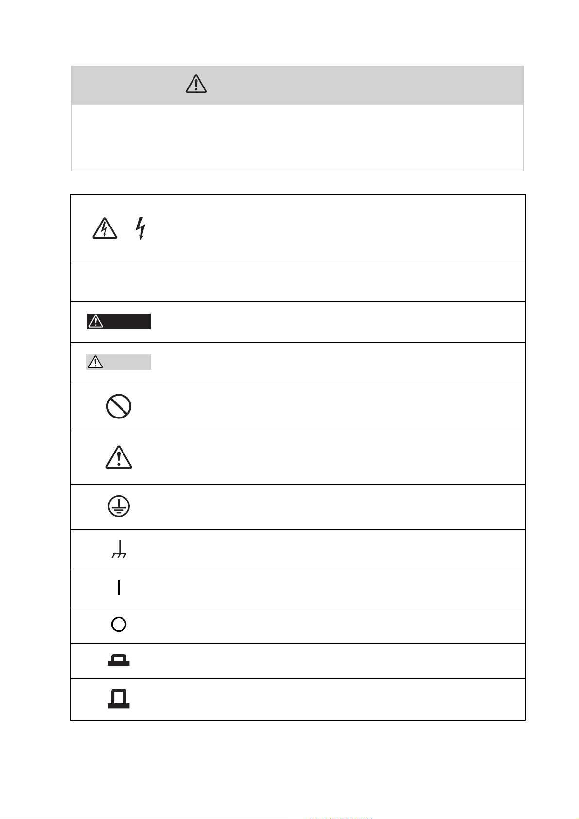
Safety Symbols
For the safe use and safe maintenance of this product, the following
symbols are used throughout this manual and on the product. Understand the meanings of the symbols and observe the instructions they
indicate (the choice of symbols used depends on the products).
Indicates that a high voltage (over 1000 V) is used here. Touching
or
the part causes a possibly fatal electric shock. If physical contact
is required by your work, start work only after you make sure that
no voltage is output here.
DANGER
WARNING
CAUTION
Indicates an imminently hazardous situation which, if ignored, will
result in death or serious injury.
Indicates a potentially hazardous situation which, if ignored,
could result in death or serious injury.
Indicates a potentially hazardous situation which, if ignored, may
result in damage to the product and other property.
Shows that the act indicated is prohibited.
Is placed before the sign “DANGER,” “WARNING,” or “CAUTION”
to emphasize these. When this symbol is marked on the product,
see the relevant sections in this manual.
Protective conductor terminal.
Chassis (frame) terminal.
On (supply)
Off (supply)
In position of a bi-stable push control
Out position of a bi-stable push control
TOS6200A/6210 Safety Symbols 1

Contents
Safety Symbols ____________________________________________ 1
Chapter 1 General ________________________________________ 1-1
Chapter 2 Installation and Preparation for Use __________________ 2-1
1.1 Overview of the Manual ----------------------------------1-2
1.2 Introduction and Features ---------------------------------1-3
1.3 Options ---------------------------------------------1-6
2.1 Unpacking Checks --------------------------------------2-2
2.2 Precautions for Installation --------------------------------2-3
2.3 Connecting the AC Power Cord -----------------------------2-4
2.4 Connecting the Test Leads --------------------------------2-5
2.4.1 Supplied Test Lead TL11-TOS/TL12-TOS ----------------2-5
2.4.2 Optional Test Probe LP01-TOS/LP02-TOS ----------------2-7
2.4.3 Other Leads -------------------------------------2-8
2.4.4 Measurements Using Four Terminals --------------------2-9
2.4.5 Measurements Using Two Terminals --------------------2-9
2.4.6 Connecting to the DUT ----------------------------2-10
2.5 Preliminary Inspection ----------------------------------2-11
Chapter 3 Part Names and Functions _________________________ 3-1
3.1 Front Panel -------------------------------------------3-2
3.2 Rear Panel -------------------------------------------3-6
Chapter 4 Basic Operation__________________________________ 4-1
4.1 Turning on the power ------------------------------------4-2
4.2 Setting the Test Conditions --------------------------------4-3
4.2.1 Test Current -------------------------------------4-4
4.2.2 Test Frequency -----------------------------------4-5
4.2.3 Upper Reference Value ------------------------------4-5
4.2.4 Lower Reference Value -----------------------------4-8
4.2.5 Test Time -------------------------------------4-11
4.2.6 Offset Canceling Function --------------------------4-12
4.3 Starting and Ending Test --------------------------------- 4-14
4.3.1 Starting a Test ----------------------------------- 4-14
4.3.2 Ending the Test ----------------------------------4-15
4.4 System Setup ---------------------------------------- 4-17
4.5 Interface Setup ---------------------------------------4-22
4.5.1 GPIB Address -----------------------------------4-22
4.5.2 RS-232C Protocol -------------------------------- 4-23
4.6 Panel Memory ----------------------------------------4-24
4.6.1 Storing in the Panel Memory ------------------------4-25
2 Contents TOS6200A/6210

4.6.2 Recalling the Panel Memory ------------------------- 4-26
4.7 Program -------------------------------------------- 4-27
4.7.1 Recalling the Program ----------------------------- 4-28
4.7.2 Creating or Editing the Program ----------------------- 4-28
4.7.3 Running the Program ----------------------------- 4-30
4.7.4 Suspending the Program ---------------------------- 4-30
4.7.5 PASS/FAIL Judgment During Program Execution ---------- 4-30
4.7.6 Ending the Program ------------------------------- 4-31
4.8 Key Lock ------------------------------------------- 4-32
4.9 Checking the Test Conditions ----------------------------- 4-32
4.9.1 Setting Output out of the Operation Range --------------- 4-33
4.9.2 Upper Reference Value <= Lower Reference Value (UP <= LOW) 435
4.10 Protection Fuction ------------------------------------- 4-36
4.10.1 Time Limitation with Respect to Output (OVER HEAT) ----- 4-37
4.10.2 Overheating Protection (OVER HEAT) ----------------- 4-38
4.10.3 Overload Protection (OVER LOAD) ------------------- 4-38
4.10.4 Output Voltage Limitation (VOLT LIMIT) --------------- 4-39
4.10.5 Change in ENABLE Signal (SIGNAL I/O) --------------- 4-40
4.10.6 Output current error (CURR ERROR) ------------------ 4-40
4.11 Initialize ------------------------------------------- 4-41
Chapter 5 REMOTE and SIGNAL I/O _________________________ 5-1
5.1 REMOTE Terminal ------------------------------------- 5-2
5.2 SIGNAL I/O Connector ---------------------------------- 5-3
5.2.1 SIGNAL I/O Connector Specifications ------------------ 5-4
5.2.2 Starting a Test ------------------------------------ 5-6
5.2.3 Recalling a Panel Memory and Program ------------------ 5-7
5.2.4 Examples of Use --------------------------------- 5-8
Chapter 6 GPIB and RS-232C _______________________________ 6-1
6.1 Interface --------------------------------------------6-2
6.1.1 GPIB Interface ----------------------------------- 6-2
6.1.2 RS-232C Interface --------------------------------- 6-2
6.2 Message and Terminator ---------------------------------6-4
6.2.1 Messages --------------------------------------- 6-4
6.2.2 Terminator ------------------------------------- 6-6
6.2.3 Special Symbols and Characters ----------------------- 6-6
6.3 Device Messages --------------------------------------- 6-7
6.3.1 Register-Related and General-Purpose Messages ------------ 6-7
6.3.2 System-Related Messages -------------------------- 6-13
6.3.3 Messages Relating to Test Conditions and Test Execution ---- 6-18
6.3.4 Messages Relating to the Tester Status ------------------ 6-26
6.3.5 Memory-Related Messages ------------------------- 6-29
6.3.6 Program-Related Messages ------------------------- 6-32
TOS6200A/6210 Contents 3

6.4 Registers ------------------------------------------- 6-36
6.5 List of Device Messages --------------------------------- 6-40
Chapter 7 Maintenance ____________________________________ 7-1
7.1 Cleaning --------------------------------------------7-2
7.2 Inspection --------------------------------------------7-2
7.3 Checking and Replacing the Fuse ----------------------------7-3
7.4 Replacing the Cooling Fan and Backup Battery ------------------7-4
7.5 Calibration -------------------------------------------7-4
7.6 In Case of Problems -------------------------------------7-5
Chapter 8 Specifications ___________________________________ 8-1
8.1 Basic Performance --------------------------------------8-2
8.2 Interface and Other Functions ------------------------------8-4
8.3 General Specifications -----------------------------------8-6
8.4 External Dimensions ------------------------------------8-8
Appendix _______________________________________________ A-1
A.1 Operational Principle ------------------------------------A-1
A.2 ASCII Codes 20H to 7EH ---------------------------------A-2
A.3 Initial Settings of the Memory ------------------------------A-3
A.4 Summary of the Safety Standards for Earth Continuity Testing --------A-4
Index ___________________________________________________ I- 1
4 Contents TOS6200A/6210

1
1
Chapter 1 General
Gives an overview of the tester and describes its features and various options.
TOS6200A/6210 1-1

1.1 Overview of the Manual
This operation manual is for the TOS6200A/6210 earth continuity tester.
■ Firmware version of products applied
This Operation Manual applies to products with version 2.0x firmware installed.
The ROM version number is displayed in the opening screen displayed immediately
after power is switched ON. You can also obtain the ROM version number with the
*IDN? message. For information on the *IDN? message, see 6.3.1, "RegisterRelated and General-Purpose Messages."
Before making product inquiries, please have ready the tester ROM version number
and serial number indicated on the rear panel of your tester.
TOS6200A
EARTH CONTINUITY TESTER
Ver. 1.01
KIKUSUI ELECTRONICS CORP.
Fig.1-1 Opening screen for firmware version 1.01
(Example of TOS6200A)
1-2 General TOS6200A/6210
1.2 Introduction and Features
This tester is used to perform earth continuity tests required for class-I devices for
various safety standards, including the IEC, EN, UL, VDE, BS, JIS, and the Electrical Appliance and Material Control Law of Japan.
The tester must be used under the following conditions:
TOS6200A TOS6210
Test current value 3Aac to 30 Aac 6Aac to 60 Aac
Output terminal voltage 5.4 V or less
Resistance value 1.2 or less 0.6 or less
Maximum power 150 VA or less 220 VA or less
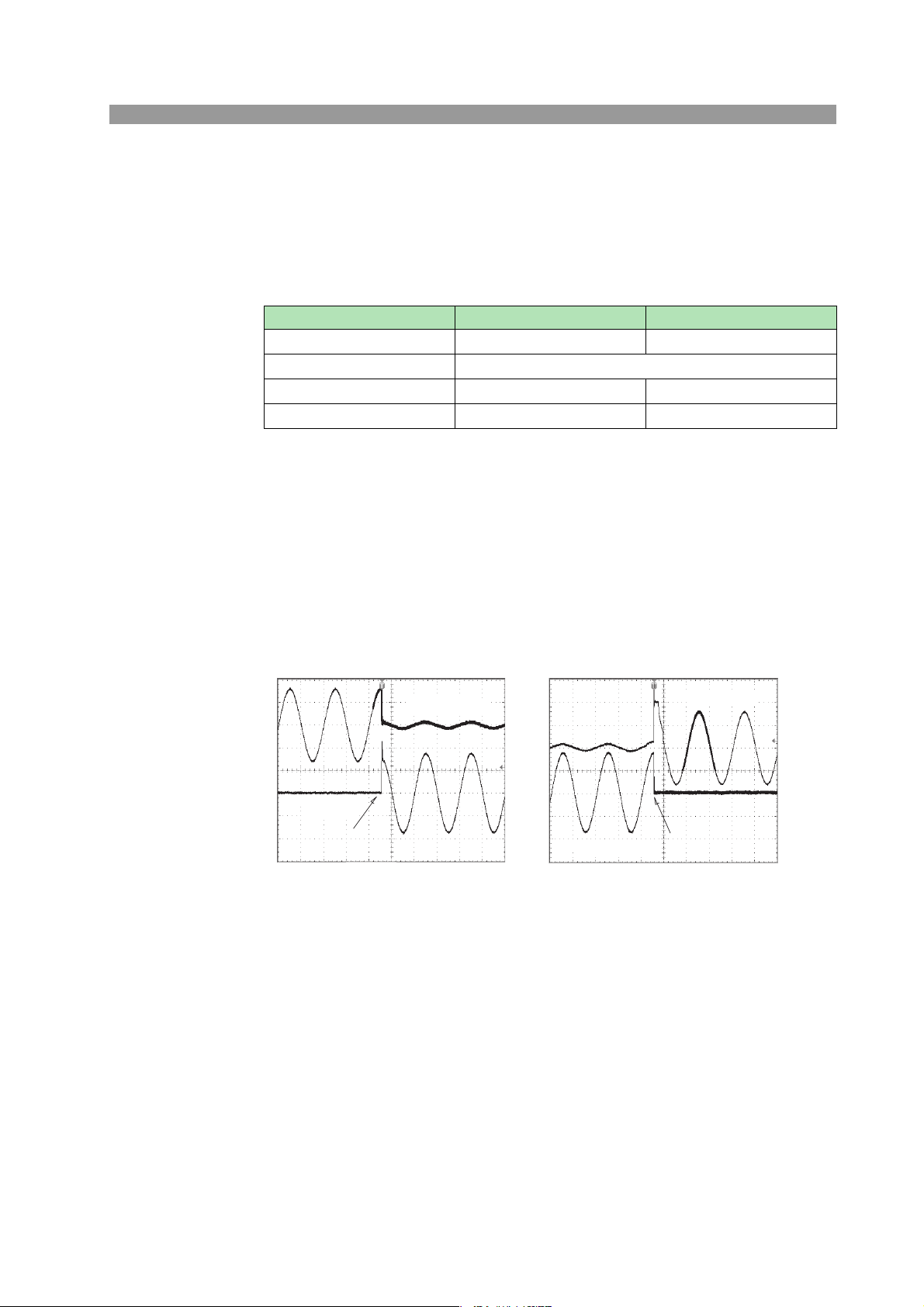
• Making test current constant
The test current for earth continuity tests has been made constant. This eliminates
the need to alter the test current, even if the resistance of the DUT (device under
test) changes.
• Safety output voltage
The constant current/constant voltage circuit provides fast response, preventing
generation of excessive output voltage even when output is interrupted during testing. The tester complies with the limitations on no-load output voltages (6 V or
less,
12 V or less, and so on) required by many safety standards.
CH1: Voltage waveform
CH2: Current
waveform
Short circuit
CH1: 5 V/div CH2: 50 A/div 10 ms/div
TOS6210
CH1:Voltagewaveform
CH2:Currentwaveform
CH1: 5 V/div CH2: 50 A/div 10 ms/div
Open
TOS6210
TOS6200A/6210 General 1-3

• Reduced cycle time
A test current is a constant current value set within approximately 100 ms.
Earth continuity tests can be conducted even at 1-second intervals. This enables
the instrument to perform tests in production lines that require reduced cycle
times.
CH1: Current waveform
TOS6210
CH1: 50 A/div 20 ms/div
• Compact and lightweight
A new high-efficiency power supply (achieving a power conversion efficiency of
65%) and large output (TOS6200A: 150 VA, TOS6210: 220 VA) makes possible a
tester that is remarkably compact and lightweight, about half the size and weight
of our conventional testers.
• Excellent measurement accuracy
The tester is equipped with an ohmmeter of +/-(2% of reading + 0.003 ) that calculates resistance values based on measured current and voltage.
• Offset canceling function
The tester has an offset canceling function that cancels values for contact resistance at alligator clip connections, the contact resistance of measuring leads in
measurements using two terminals, and other resistance components.
• Contact check function
The tester is provided with a contact check function that verifies the connection of
the DUT (by current detection) before initiating testing.
• Voltage judgment function
This function allows either a resistance value or a voltage drop value (voltage
between the SAMPLING terminals) to be selected as the reference value for judgment criteria.
It also allows voltage drop value-based testing to be conducted, which is required
by safety standards such as UL 60950-1 and IEC 60950-1.
• Simple operations
Tester functions are fast and easily controlled, with an intuitive control method
that's easy to pick up, even for first-time users.
For example, test conditions are set simply by selecting an item displayed on the
LCD with the cursor keys and turning the rotary knob to set/select a value.
Any items you wish to set up can be assigned to the function keys.
1-4 General TOS6200A/6210

• Stores up to 100 types of test conditions
The tester allows you to store and name up to 100 test conditions involving parameters such as test current, determined resistance value, and test time. For example,
you can store test conditions for a specific safety standard under the name of the
standard, or store test conditions under the name of the destination of the DUT.
When test conditions need to be modified due to changes in the destination of the
product or revised safety standards, you can recall a set of test conditions simply
by entering a memory number, making necessary modifications to the pre-existing
standard.
Assigning specific names allows test conditions to called up by name. This function is available through both the front panel and the remote control.
• Programming of test conditions
A combination of stored test conditions allows automatic execution of tests consisting of several programs of up to 100 steps each.
Although the total number of steps is limited to 500, 100 types of programs can be
stored and recalled from the front panel or the remote control.
• GPIB and RS-232C interfaces
The tester is provided with standard GPIB and RS-232C interfaces. It is therefore
not necessary to buy additional GPIB and RS-232C boards.
An interface cable and PC or sequencer allows remote control of test conditions
such as test current, determined resistance value, and testing time. Measured values and test results can also be read back.
• Supplied test leads
The tester comes with alligator clip test leads, letting you start testing immediately.
• Memo function
The tester has a memo function that can store up to 20 characters per line on 3
lines, which can be used to store serial numbers, calibration dates, and/or comments.
TOS6200A/6210 General 1-5
1.3 Options
The following options are available for the tester.
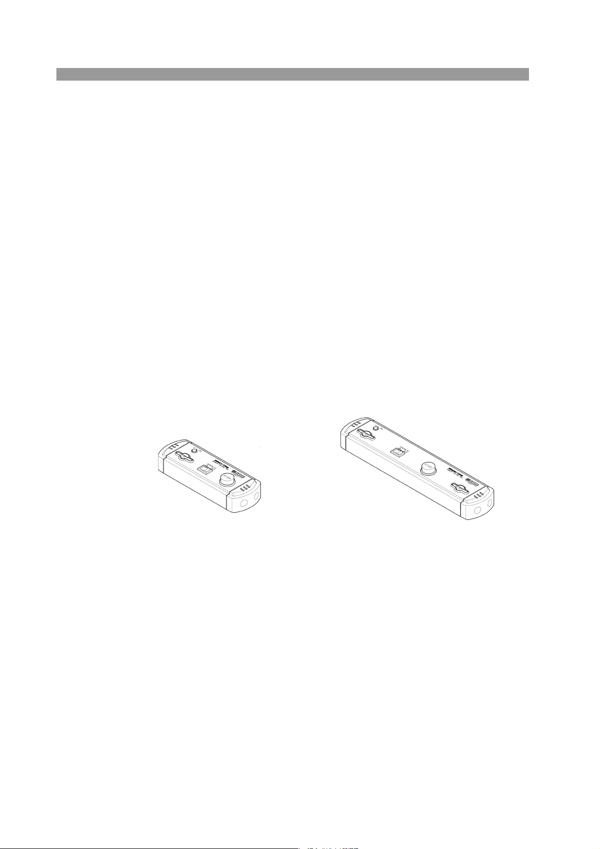
■ RC01-TOS/RC02-TOS Remote Control Box
When connected to the REMOTE terminal on the front panel, remote control boxes
are used to control tester start/stop functions.
The RC01-TOS has one START switch, while the RC02-TOS has two START
switches. For the RC02-TOS, a test starts only when both switches are pressed
simultaneously.
Functions
OPERATE switch
Test switches are enabled only when this switch is set to the ON position.
When it is set to the OFF position, a test in progress will be stopped.
START switch
With the OPERATE switch set to ON and the tester in ready status, press this
switch to start testing.
STOP switch
Used to shut off output voltage or cancel a FAIL status; has the same function
as the STOP switch located on the tester.
RC01-TOS:
200mm(W) x 70mm(H) x 39mm(D)
1-6 General TOS6200A/6210
RC02-TOS:
330mm(W) x 70mm(H) x 39mm(D)
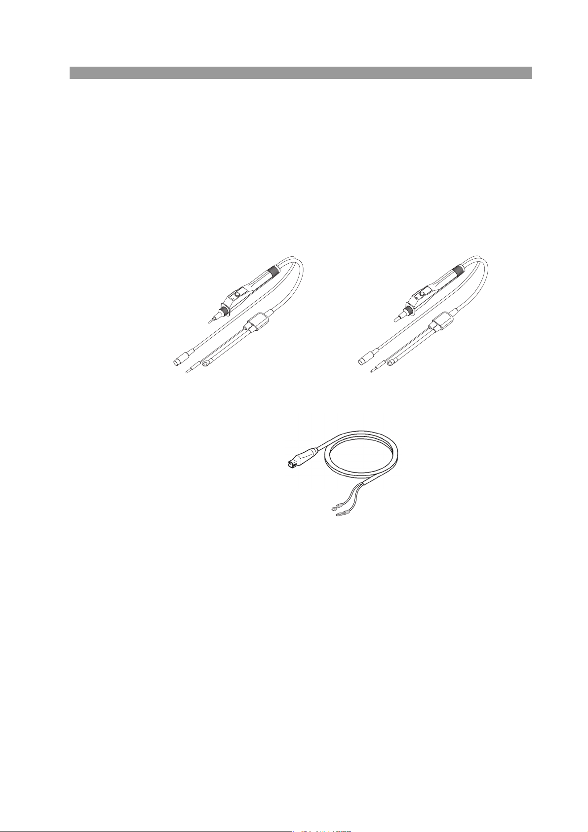
■ LP01-TOS/LP02-TOS Test Probe
This probe lets you use the switches located on the probe to control tester starting
test/stopping test operations. Connect it to the OUTPUT and REMOTE terminals
on the tester's front panel.
Maximum rating: LP01-TOS 30 A
LP02-TOS 60 A
Cable length: 2 m
Accessory: LOW Test Lead (LP01-TOS/LP02-TOS) 2 m
LP01-TOS:
28 mm(W) x 45.5 mm(H) x 226 mm(D)
LOW Test Lead
LP02-TOS:
28 mm(W) x 45.5 mm(H) x 226 mm(D)
TOS6200A/6210 General 1-7

1-8 General TOS6200A/6210

2
2
Chapter 2 Installation and
Preparation for Use
Describes the steps from unpacking to installation to preparation required before
switching on POWER.
TOS6200A/6210 2-1
2.1 Unpacking Checks
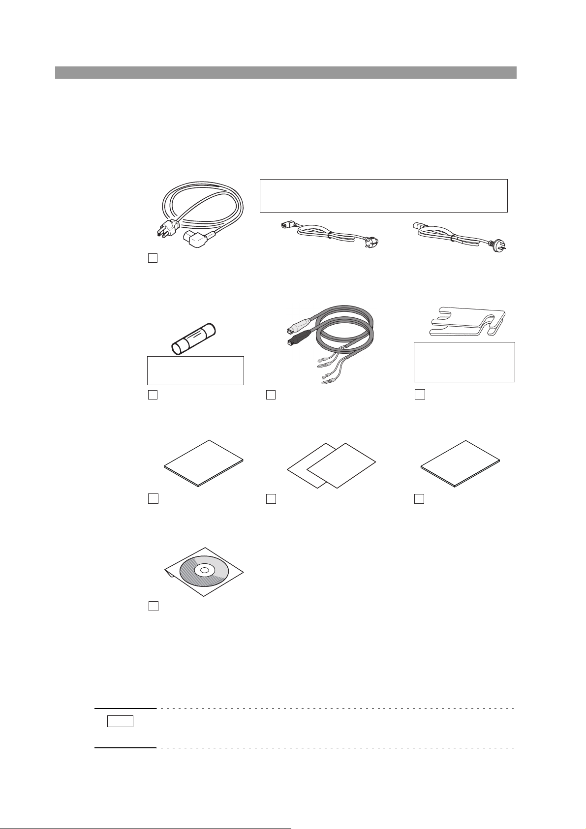
Upon receiving the product, make sure the package contains the necessary accessories, and that the product has not been damaged during transportation.
If any damage or imperfection is found, contact Kikusui distributor/agent.
The power cord that is provided varies depending on
the destination for the product at the factory-shipment.
or or
AC power cord, 1
Rated voltage: 125 Vac
PLUG: NEMA5-15
[85-AA-0003]
Inserted in the
AC LINE connector
Spare fuse, 1
6.3 A 250 V
[99-02-0019]
Setup Guide (1 pc.)
[Z1-006-310]
Rated voltage: 250 Vac
PLUG: CEE7/7
[85-AA-0005]
Test leads, 1 set
TOS6200A: TL11-TOS 1.5 m
TOS6210: TL12-TOS 1.5 m
Quick Reference
English: 1 pc. [Z1-006-322]
Japanese: 1 pc. [Z1-006-320]
Rated voltage: 250 Vac
PLUG: GB1002
[85-10-0790]
Installed between
the OUTPUT and
SAMPLING terminals
Short-circuit bars, 2
[E3-300-032]
Safety Information
(1 pc.)
[Z1-005-040]
CD-ROM (1 pc.) ᳕SA-6061᳗
Fig.2-1 List of Accessories
SIGNAL I/O, GPIB interface, and RS-232C interface cables are not supplied with
the product and must be purchased separately.
For information on connecting those cables, see 5.2, "SIGNAL I/O Connector” and
6, "GPIB and RS-232C.”
NOTE
• Packing materials may be used for later transport of the product, so it is recommended that they be retained.
2-2 Installation and Preparation for Use TOS6200A/6210
2.2 Precautions for Installation
When installing this product, be sure to observe the precautions provided in "Precautions Concerning Installation Location" in the Safety information manual. Items
specific to this product are given below.
Precautions for installation location
When you install the product, be sure to observe the temperature and
humidity ranges indicated below.
Operating temperature range:5 Cto35C (41 Fto95F)
Operating humidity range:20 %rh to 80 %rh (no dew condensation is allowed)
When you store the product, be sure to observe the temperature and
humidity ranges indicated below.
Storage temperature range:-20 Cto+70C (-4 F to +158 F)
Storage humidity range:90 %rh or less (no dew condensation is allowed)
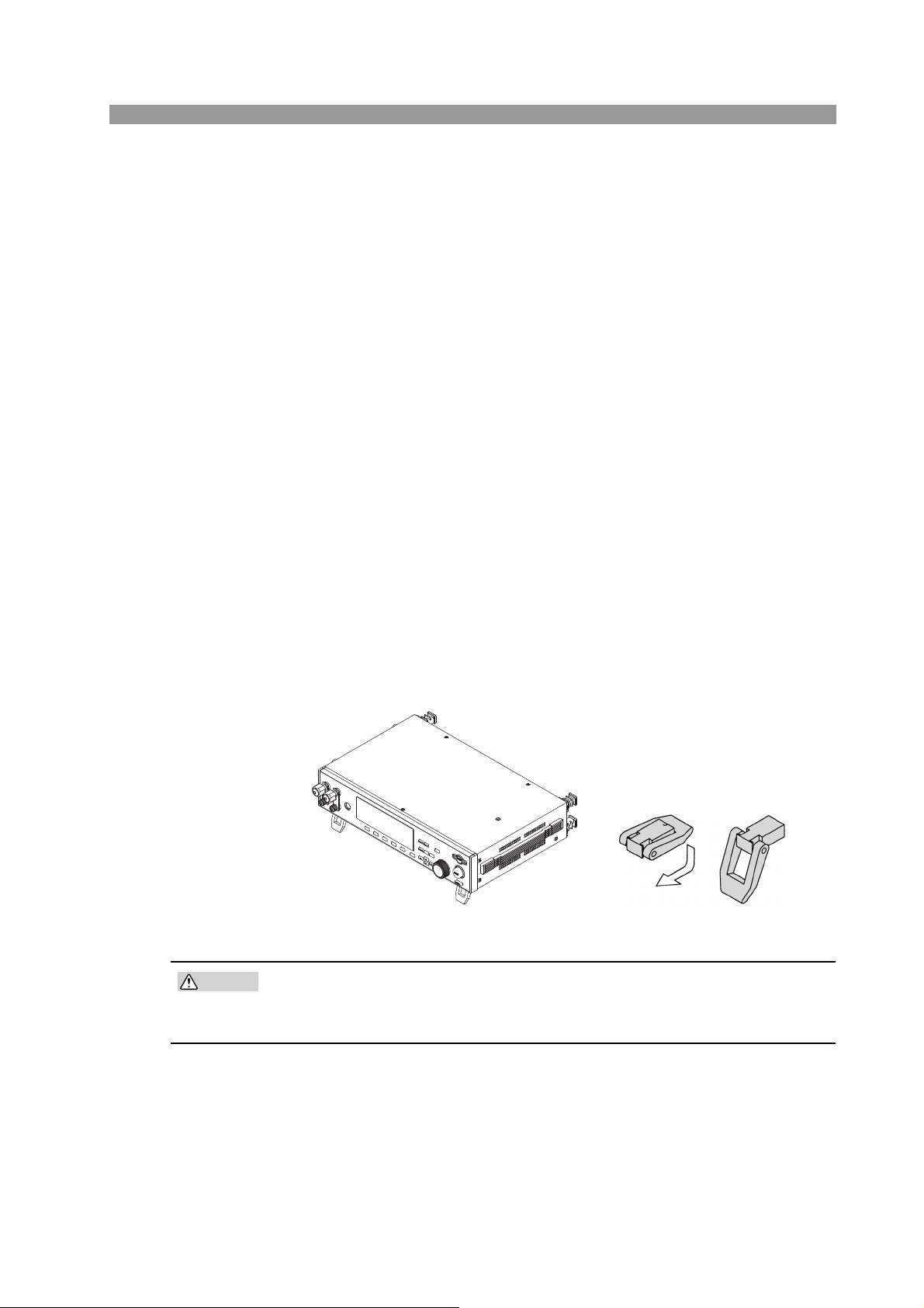
Use of the feet
CAUTION
Used to raise the front panel of the meter to get a better view of the LCD screen or
improve the operability of the keys.
Pull the provided feet forward onto the floor until you hear them click.
Fig. 2-2 How to use the feet
• Do not use the rubber strips on the sides as feet. Use of the product in an
upright position with a rubber strip at the bottom may cause the product to
fall down, resulting in damage to the tester or injury to the user.
TOS6200A/6210 Installation and Preparation for Use 2-3
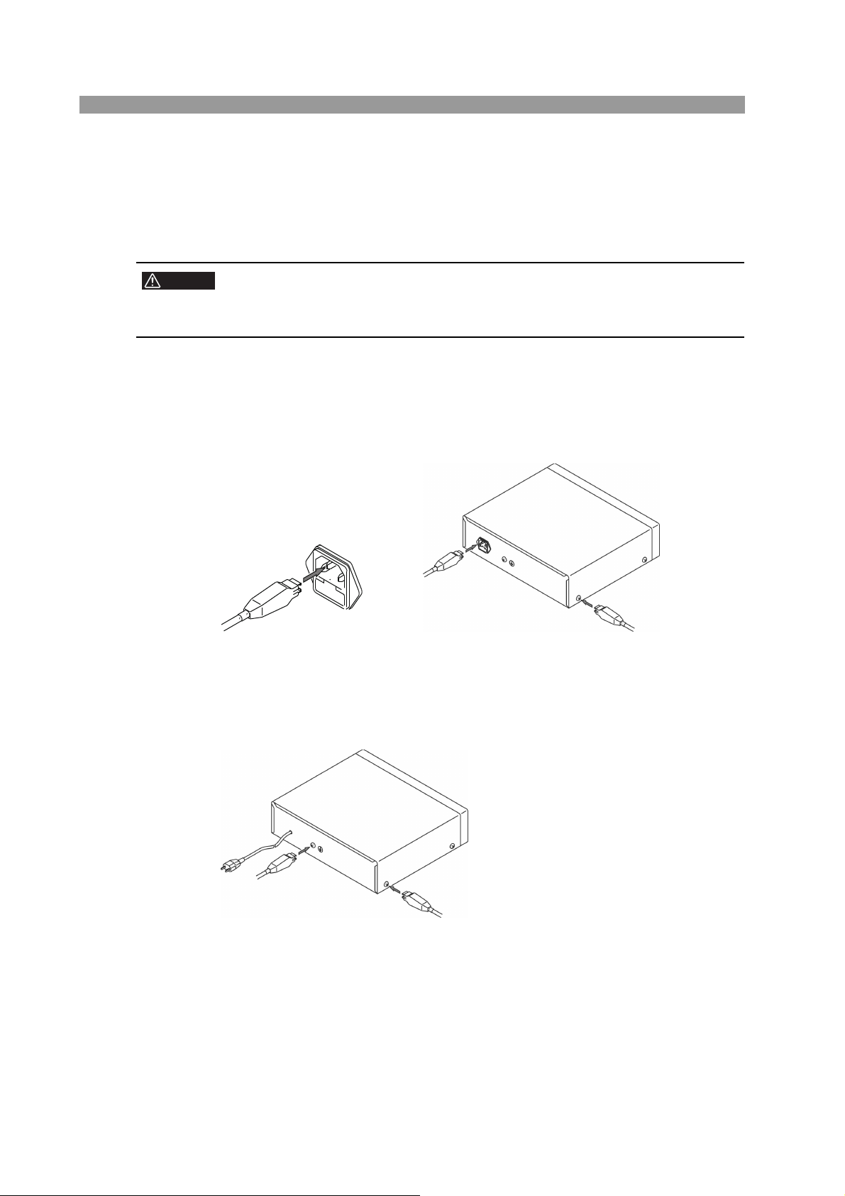
2.3 Connecting the AC Power Cord
WARNING
NOTE
• This product is a piece of equipment that conforms to IEC Safety Class I
(equipment that has a protective conductor terminal). Be sure to earth
ground the product to prevent electric shock.
The product is grounded through the power cord ground wire. Connect the
protective conductor terminal to earth ground.
• Use the supplied power cord to connect to the AC line.
If the supplied power cord cannot be used because the rated voltage or the plug
shape is incompatible, have a qualified engineer replace it with an appropriate
power cord that is 3 m or less in length. If obtaining a power cord is difficult, contact your Kikusui agent or distributor.
• The power cord with a plug can be used to disconnect the product from the AC
line in an emergency. Connect the plug to an easily accessible power outlet so that
the plug can be removed from the outlet at any time. Be sure to provide adequate
clearance around the power outlet.
• Do not use the supplied power cord for other devices.
This product is a piece of equipment that conforms to IEC Overvoltage Category II
(energy-consuming equipment that is supplied from a fixed installation).
Procedure
1. Check that the POWER switch is turned off.
2. Check whether the AC power line is compatible with the input rating of
the Tester.
The product can receive a nominal power supply voltage in the range of 85 Vac
to 250 Vac at a frequency of 47 Hz or 63 Hz.
The input voltage range is also indicated under LINE VOLTAGE RANGE on
the rear panel.
3. Connect the power cord to the rear-panel AC inlet, and then connect
the power plug to an outlet that has a ground terminal.
2-4 Installation and Preparation for Use TOS6200A/6210
2.4 Connecting the Test Leads
WARNING
CAUTION
• This product carries a maximum current flow of 30 A or 62A. Always check
to make sure that no connections are loose. Loose connection will result in
overheating of the OUTPUT terminals or the DUT (Device Under Test),
which may then result in burns or injury.
• Never connect the voltage measurement cable (thin wire) of the supplied
test leads or optional test probe to the OUTPUT terminals. The nominal
sectional area of this wire is inadequate for such currents, and burning
may result.
• This product carries a large current and consequently generates a strong
magnetic field. Make sure that no articles that may be affected by magnetic fields are located near the test leads or current output lines.
For example, images on a CRT positioned close by may be significantly
distorted.
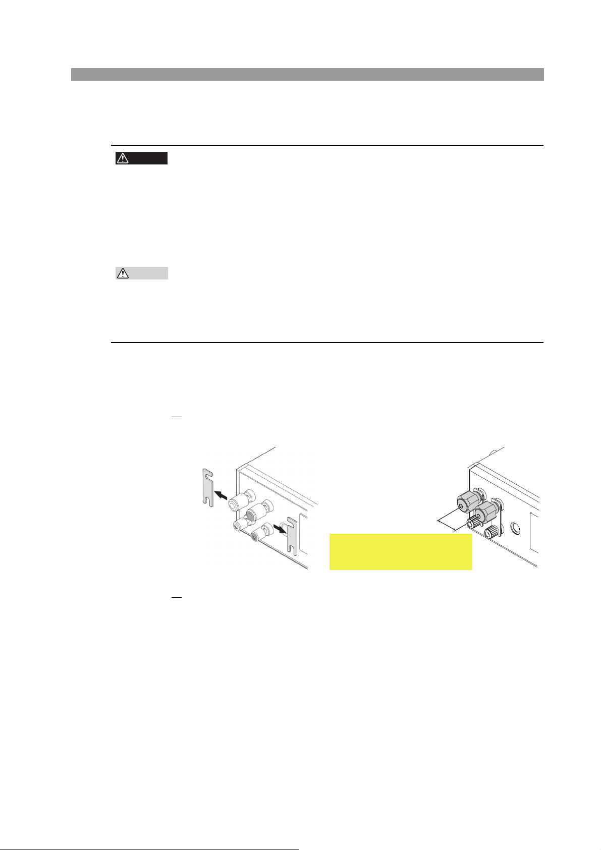
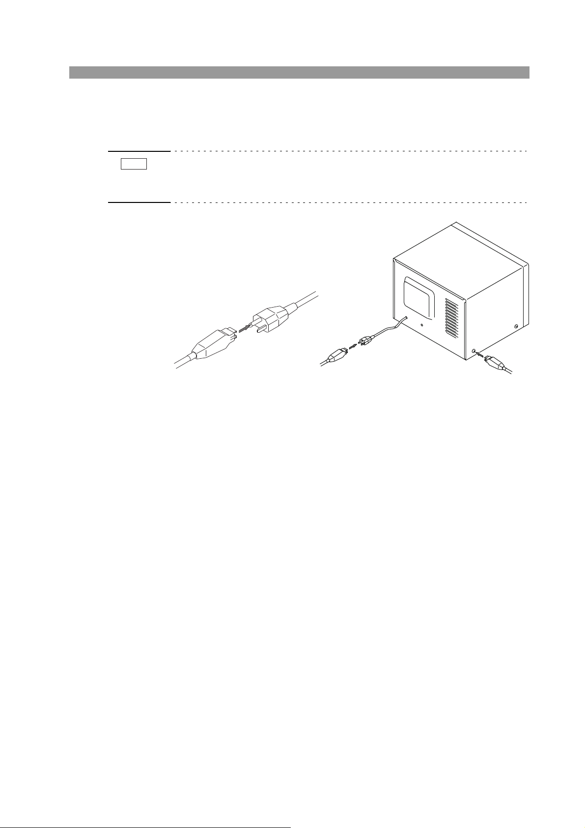
2.4.1 Supplied Test Lead TL11-TOS/TL12-TOS
1. Remove the short-circuit bars connecting the OUTPUT and SAMPLING
terminals.
TOS6200A
Take care not to get your finger
caught between the output
terminals when turning the knobs.
TOS6210
2. Connect the current output line on the crimp terminal side of the test
lead (black or white) to the LOW side of the OUTPUT terminals; connect the voltage measurement line on the banana plug side to the LOW
side of the SAMPLING terminals. Check that the connections are
secure.
TOS6200A/6210 Installation and Preparation for Use 2-5
3. Connect the current output line on the crimp terminal side of the test
lead (red) to the HIGH side of the OUTPUT terminals; connect the voltage measurement line on the banana plug side to the HIGH side of the
SAMPLING terminals. Check that the connections are secure.
WARNING
• Improper terminal connections can result in inaccurate measurements and
burns or injury resulting from heat generated by contact resistance at the
terminals.
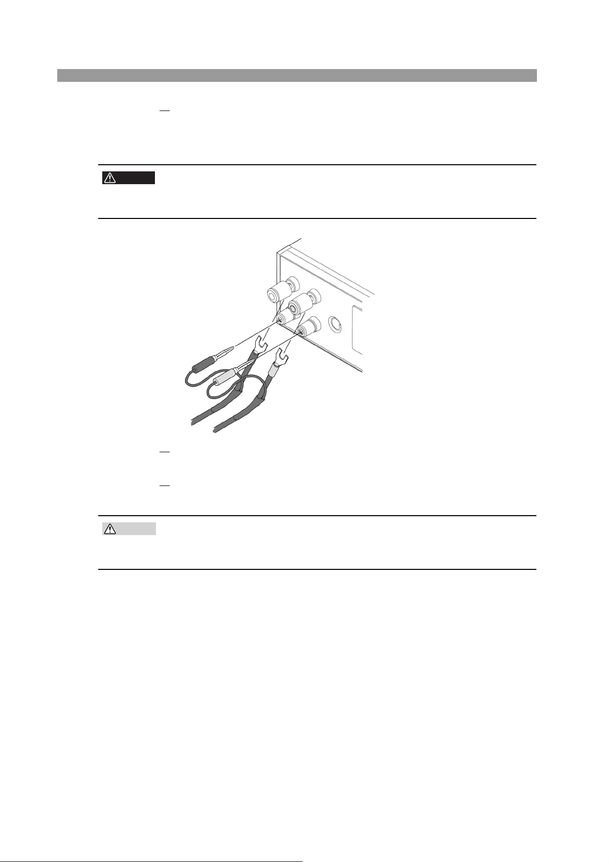
Connecting example of TOS6200A
4. Connect the alligator clip of the test lead (black or white) to the protec-
tive conductor terminal of the DUT.
CAUTION
5. Connect the alligator clip of the test lead (red) to a test point of the DUT.
For details, see 2.4.6, "Connecting to the DUT”
• Make sure that the alligator clip connections are secure.
Improper connections may result in clip disconnection, causing sparking
and potentially damaging the DUT.
2-6 Installation and Preparation for Use TOS6200A/6210
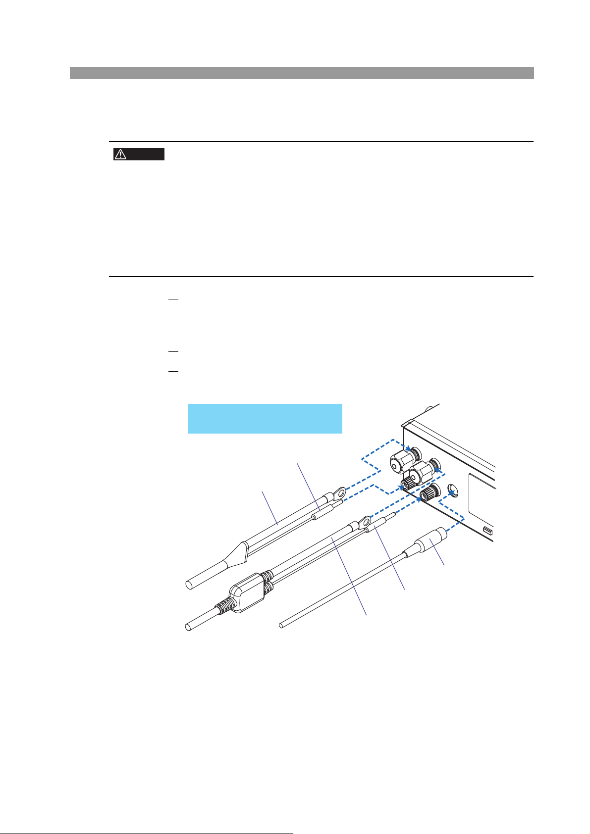
2.4.2 Optional Test Probe LP01-TOS/LP02-TOS
WARNING
• Never connect the voltage measurement cable (thin wire) of the optional
LP01/LP02-TOS test probe to the OUTPUT terminals. Its nominal sectional area is inadequate for such currents, and burning may occur.
• The rated current of the LP01-TOS and LP02-TOS test probes are up to
30 A and 60 A, respectively. Do not attempt to pass a current exceeding
the rated current.
• Improper terminal connections can result in inaccurate measurements and
burns or injury resulting from heat generated by contact resistance at the
terminals.
1. Turn off the POWER switch of the Tester.
2. Remove the short-circuit bars connecting the OUTPUT and SAMPLING
terminals.
3. Connect the LOW test lead to the LOW terminal of the Tester.
4. Connect the each cable of the test probe to the HIGH and REMOTE ter-
minal of the Tester.
Figure shows connections of the
TOS6210 with the LP02-TOS.
TOS6210
To OUTPUT
LOW terminal
To SAMPLING
LOW terminal
To the REMOTE terminal
To SAMPLING
HIGH terminal
To OUTPUT
HIGH terminal
TOS6200A/6210 Installation and Preparation for Use 2-7
2.4.3 Other Leads
WARNING
CAUTION
• If you use a lead wire other than those supplied with the product, select
wires of the nominal sectional areas meeting the test current.
• To avoid generating excessive heat at the connections, use crimp terminals appropriate for the sectional area of the current output line.
Select wires on the basis of the following criteria.
Test Current (I) Required Nominal Sectional Areas of Wire
I30 A
30<I60 A
5.5 mm2or more
2
14 mm
or more
Resistance values with respect to the nominal sectional areas of wires are as follows:
Use lead wires within a total lead length of 10 m or less.
Nominal Sectional Areas of Wire Resistance Value per Meter
5.5 mm
14 mm
2
2
3.5 m
1.5 m
2-8 Installation and Preparation for Use TOS6200A/6210
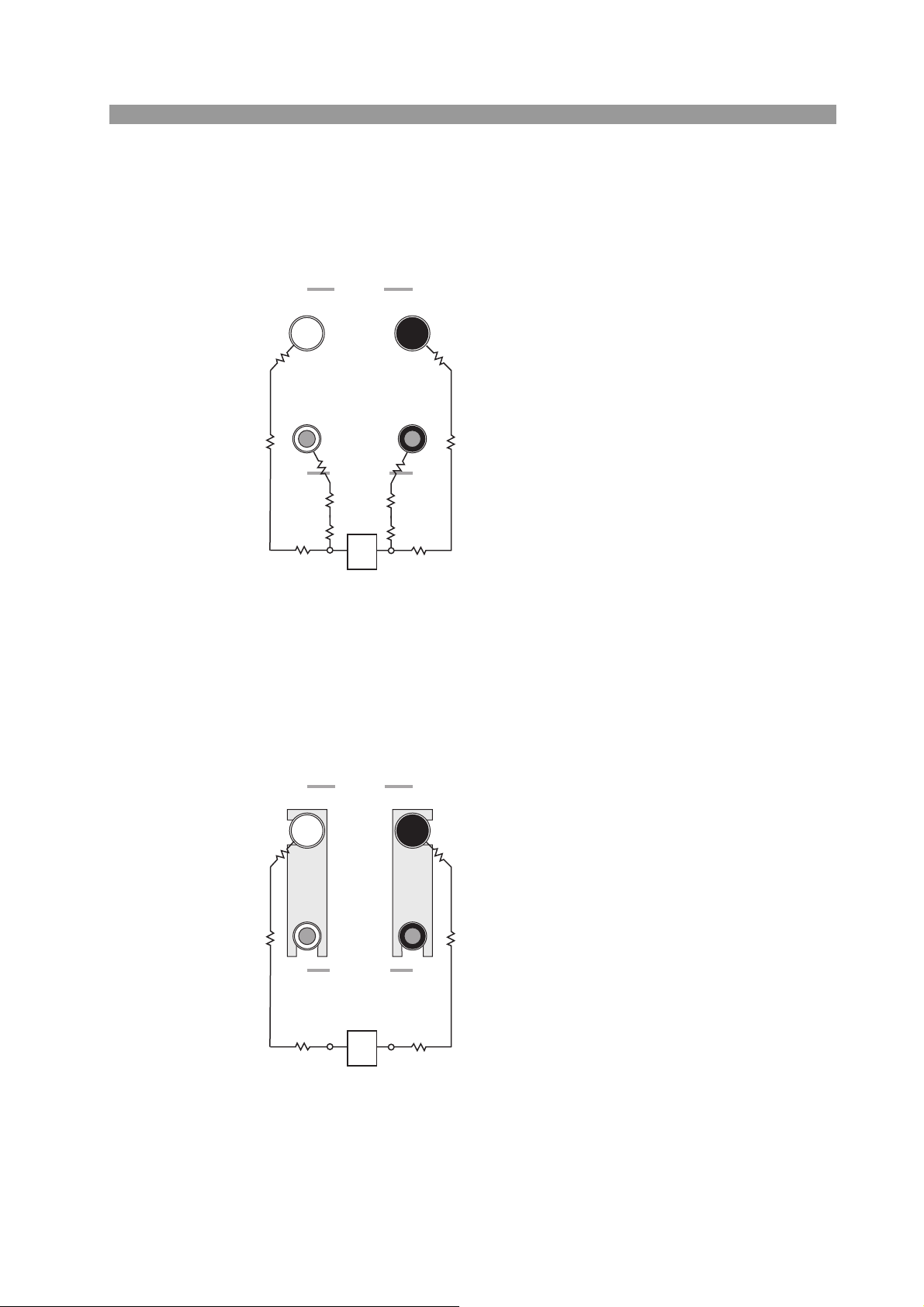
2.4.4 Measurements Using Four Terminals
Four-terminal measurements allow the tester to measure the resistance of the DUT,
excluding the minute resistance of the leads, contact resistance of the OUTPUT terminals, and other non-essential characteristics.
OUTPUT
LOW HIGH
r1
R1
r5 r6
LOW HIGH
SAMPLING
R3 R4
r7 r8
r3
AB
DUT: Device Under Test
r2
R2
r4
Fig. 2-3 Four-Terminal Connection
Remove the short-circuit bars connecting the OUTPUT and SAMPLING terminals and connect the
leads.
Sampling the voltage between A and B allows the
tester to measure the resistance between A and B
without interference from the effects of contact resistance r1 to r8 and resistance components R1 to R4 of
the leads.
r1 to r8: Contact resistance
R1 to R4: Resistance of the leads
2.4.5 Measurements Using Two Terminals
Perform two-terminal measurements if four-terminal measurements can't be made.
Note that measurements using two terminals will include the resistance components
of the leads and the contact resistance of the OUTPUT terminals.
OUTPUT
LOW HIGH
r1
R1 R2
LOW HIGH
SAMPLING
r3 r4
AB
DUT: Device Under Test
r2
Fig. 2-4 Two-Terminal Connection
Install the short-circuit bars between the OUTPUT
and SAMPLING terminals and connect the leads.
The tester measures the total resistance value of contact resistance r1 to r4, resistance components R1
and R2 of the leads, and the resistance between A
and B.
r1 to r4: Contact resistance
R1 to R2: Resistance of the leads
Two-terminal measurements can be performed with the resistance components (R1,
R2) of the leads and the contact resistances (r1 to r4) of the OUTPUT terminals subtracted beforehand. For more information, see 4.2.6, "Offset Canceling Function.”
TOS6200A/6210 Installation and Preparation for Use 2-9
2.4.6 Connecting to the DUT
Connect to the DUT when the tester status is either of the following:
• Ready (“READY” displayed on the LCD)
• Waiting during a contact check (TEST LED blinking)
WARNING
• To avoid burns, do not inadvertently touch the testing point or the end of
the test probe or lead during the test or immediately after test, since they
are at high temperature.
■ Testing from the protective conductor terminal of the AC
power inlet
Connect one of the test leads to the protective conductor terminal of the AC power
inlet of the DUT; connect the other test lead to a test point.
■ Testing from the protective conductor terminal on the enclo-
sure
Connect one of the test leads to the protective conductor terminal of the DUT; connect the other test lead to a test point.
2-10 Installation and Preparation for Use TOS6200A/6210
■ Testing from the ground contact of the AC power cord
Connect one of the test leads to the ground contact of the AC power cord of the
DUT; connect the other test lead to a test point.
NOTE
• Some safety standards specify excluding the resistance value of the AC power
cord protective ground wire from testing. Check the appropriate safety standard
to determine if this is the case.
2.5 Preliminary Inspection
Always inspect the following four points before testing.
• Check that the test lead covers are free of cracks or tears.
• Check that there are no breaks in the test leads.
• Short-circuit the ends of the test leads and test at a specified current to check for
abnormalities.
• Perform the test with the OUTPUT terminals opened. This test must result in a
FAIL judgement.
TOS6200A/6210 Installation and Preparation for Use 2-11

2-12 Installation and Preparation for Use TOS6200A/6210

3
3
Chapter 3 Part Names and
Functions
Gives the names and functions of switches, keys, indications, connectors, and other
parts on the front and rear panels.
TOS6200A/6210 3-1
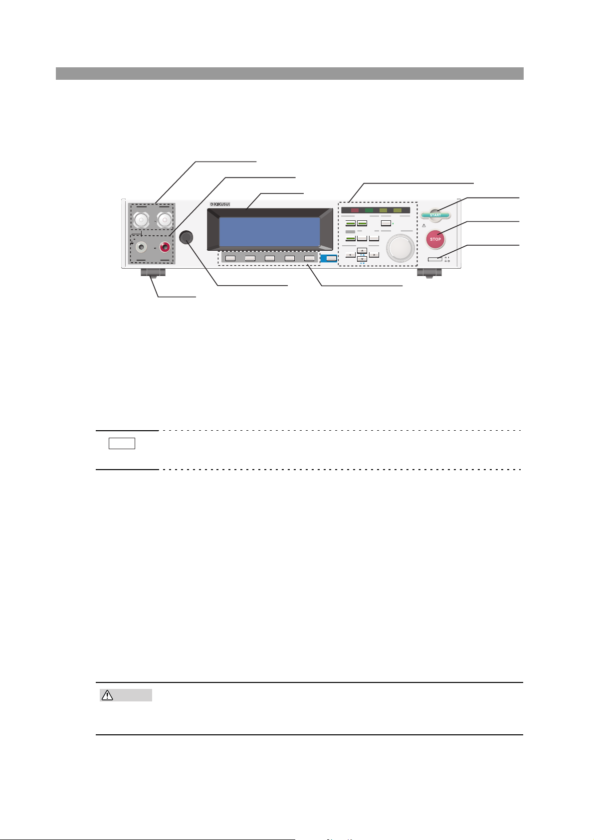
3.1 Front Panel
[4] OUTPUT
OUTPUT
HIGH
LOW
MAX
60A
MAX
20V
MAX
10V
LOW
SAMPLING
REMOTE
HIGH
[5] SAMPLING
[6] LCD
EARTH CONTINUITY TESTER TOS6210
F1 F3
F2
F1 F3
F2
Setup keys (see Fig. 3-2)
[3] START
TEST PASS
FAIL
PROTECTION
FUNCTION GPIB
MAIN SYSTEM LOCAL
OFFSET I / F KEY LOCK
MEMORY ENTRY
AUTO
RECALL
STOREEDIT
F5
F4
F5
F4
SHIFT
CURSOR
RMT
ENTER
ON 10min / OFF 10min
POWER
[2] STOP
[1] POWER
[1] POWER
NOTE
[2] STOP
[3] START
[8] REMOTE
[9] Function keys
[7] Feet
Fig.3-1 Front Panel (example of TOS6210)
Turns the tester power ON/OFF. When power is turned ON ( | ), the tester starts
under the test conditions set when power was turned OFF(O).
Turning the power ON with the SHIFT key held down initializes the tester to factory-set settings. For initialization, see 4.11, "Initialize,” and for turning the power
ON, see 4.1, "Turning on the power.”
• Initializing clears the contents of all panel memories and programs stored. Check
all data in memories and programs before initializing.
This switch is used to stop a test.
Press this switch to cancel a PASS, FAIL, or PROTECTION status.
Pressing this switch places the tester in ready status.
This switch is used to start a test.
Press this switch when "READY" is displayed on the LCD to begin testing.
During testing, the TEST LED indicator lights and a "TEST" indication appears on
the LCD.
[4] OUTPUT
These current output terminals are used to connect current output wires for testing.
CAUTION
3-2 Part Names and Functions TOS6200A/6210
• The maximum input voltage between the OUTPUT terminals and chassis
is 20 Vac/ 20 Vdc or less. Do not apply an external voltage exceeding this
limit.

[5] SAMPLING
These voltage input terminals are used to connect voltage measuring wires for fourterminal measurements.
CAUTION
• The maximum input voltage between the SAMPLING terminals is 10 Vac/
10Vdc or less. Do not apply external voltage exceeding this limit.
[6] LCD
Displays information, including the range of set values and measured values.
[7] Feet
Used to raise the front panel of the tester to get a better view of the LCD screen or
improve the operability of the keys.
For usage of the feet, see 2.2, "Precautions for Installation.”
[8] REMOTE
This terminal is used to connect an optional remote control box or dedicated test
probe.
[9] Function keys
Provide functions corresponding to the F1 to F5 menus displayed on the LCD.
TOS6200A/6210 Part Names and Functions 3-3
TEST PASS
FAIL
PROTECTION
MAIN SYSTEM LOCAL
RMT
ENTER
RECALL
STOREEDIT
OFFSET I / F KEY LOCK
SHIFT
AUTO
FUNCTION GPIB
MEMORY ENTRY
CURSOR
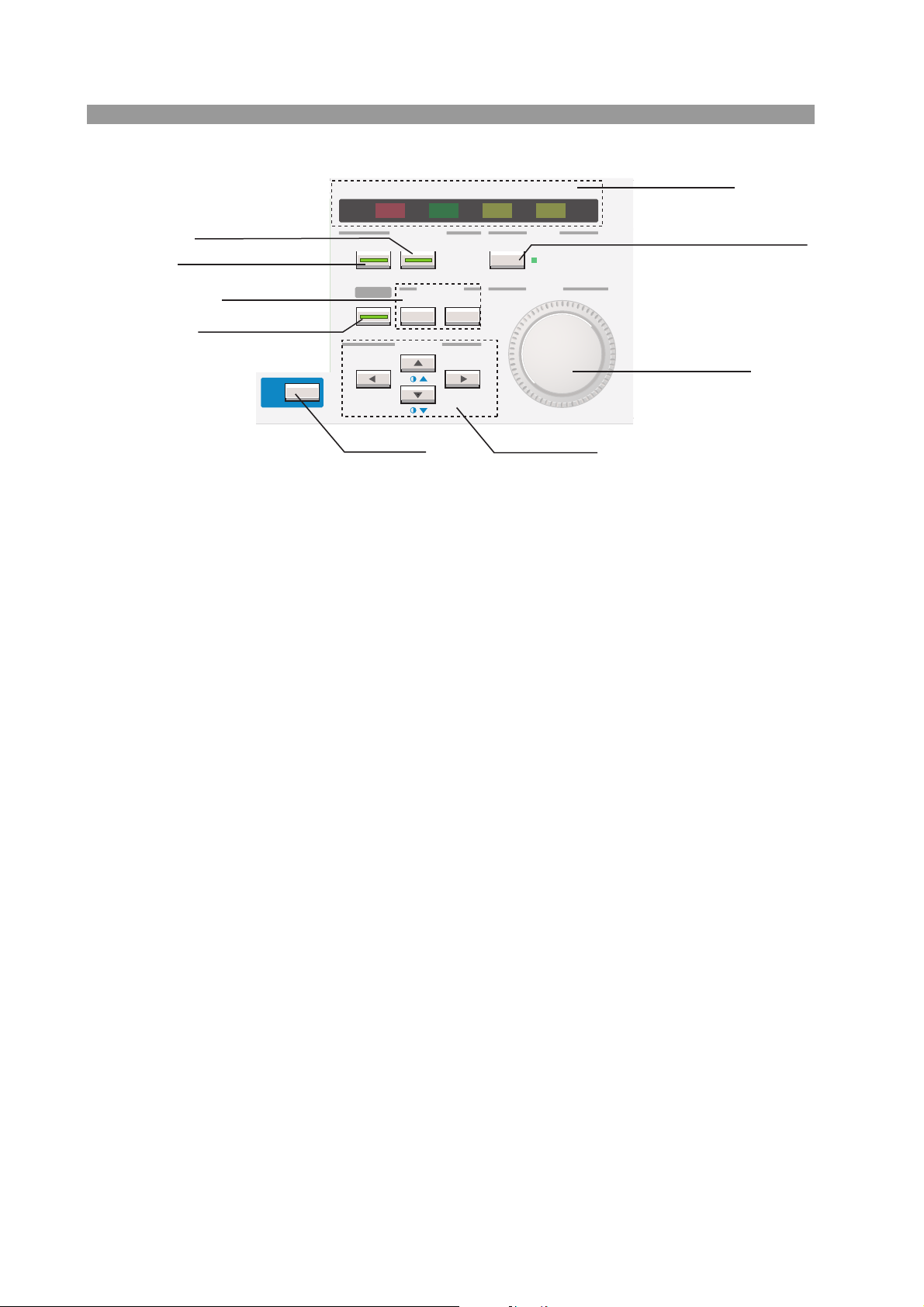
[16] Indicators
[10] SYSTEM / I/F
[11] MAIN / OFFSET
[12] MEMORY
[13] AUTO / EDIT
Fig. 3-2 Setup keys (example of TOS6210)
[10] SYSTEM / I/F
This key is used to make the system settings of the tester.
Pressing this key causes its LED lights up and displays the system setup screen on
the LCD (SYSTEM).
Pressing this key with the SHIFT key held down displays the interface setup screen
(INTERFACE) on the LCD.
[11] MAIN / OFFSET
[14] SHIFT
[17] LOCAL / KEYLOCK
[18] Rotary knob
[15] CURSOR
Pressing this key causes its LED lights up and displays the test conditions setup
screen (MAIN) on the LCD. Generally, testing is performed from this screen.
Pressing this key with the SHIFT key held down displays the offset measurement
screen (OFFSET).
[12] MEMORY
• RECALL/STORE key
• ENTER key
Press this key to recall panel memory.
Change the memory number using the rotary knob, then press the ENTER key
next to this key. This recalls the contents of the specified memory number.
Pressing this key with the SHIFT key held down enables test conditions to be
stored to memory. The procedure is the same as for recall.
Used to accept an entered memory number when recalling panel memory or
when saving test conditions to panel memory.
3-4 Part Names and Functions TOS6200A/6210
 Loading...