

Kikusui TOS5300, TOS5301, TOS5302 Communication Interface Manual
7
PART NO. IB021967
May 2019
TOS5300
TOS5301
TOS5302
Withstanding Voltage/
Insulation ResistanceTester
DANGER
This product generates high voltage!
• Improper operation can lead to serious accidents.
• To prevent accidents, be sure to read the section
“Safety Precautions during Testing” in this manual.
• Keep this manual close to the product so that the
operator can read it at any time.
Communication
Interface Manual
Remote Control 5
Remote Control Overview 6
Message Overview 9
Message Overview 10
Command Reference 15
Command Description in This Manual 16
IEEE 488.2 Common Commands 17
Test Mode Settings 20
AC Withstanding Voltage Test (ACW) Conditions
21
DC Withstanding Voltage Test (DCW) Conditions
25
Insulation Resistance Test (IR) Conditions 29
About Sequences 33
Test Execution (SEQuence2:TEST) 35
Querying Measured Values
(SEQuence1:ACQuire) 37
Various Settings 42
Status Register and Status Report Function 46
IEEE 488.2 Register Model 48
SCPI Register Model 50
Tutorial 58
Appendix 59
List of Messages 60
List of Errors 66
Default State 69
Command processing time 71
Using Visual Basic 2008 72

Thank you for purchasing the TOS5300 Series Withstanding
About the Operation Manuals
Notations Used in This Manual
See
5300
5301
5302
Memo
Voltage and Insulation Resistance Tester.
There are five TOS5300 Series Manuals listed as follows.
■ Setup Guide
This manual is intended for first-time users of this product. It
provides an overview of the product and notes on usage. It also
explains how to set up the product for testing the DUT. Always
read this manual before using the product.
Trademarks
Microsoft, Windows, and Visual Basic are registered trademarks of
Microsoft Corporation in the United States and/or other countries.
All company names and product names used in this manual are
trademarks or registered trademarks of their respective
companies.
Copyrights
The contents of this manual may not be reproduced, in whole or in
part, without the prior consent of the copyright holder.
The specifications of this product and the contents of this manual
are subject to change without prior notice.
■ Quick Reference
This manual explains Panel description and operation briefly.
■ Safety Information
This document contains general safety precautions for this
product. Keep them in mind and make sure to observe them.
■ User’s Manual (PDF)
This manual is intended for first-time users of this product. It
provides an overview of the product and notes on usage. It also
explains how to configure the product, operate the product,
perform maintenance on the product, and so on.
■ Communication Interface Manual
(this manual, PDF)
This manual contains details about remotely controlling the
tester using SCPI commands.
The interface manual is written for readers with sufficient basic
knowledge of how to control measuring instruments using a
PC.
PDF files are included in the accompanying CD-ROM.
You can view the PDF files using Adobe Reader.
The newest version of the operation manual can be downloaded
from Download service of Kikusui website.
TOS5300 Series Manuals are intended for users of the
Withstanding Voltage and Insulation Resistance Tester and their
instructors. Explanations are given under the presumption that
the reader has knowledge about the electrical aspects of electrical
safety testing.
© 2010 Kikusui Electronics Corporation
• The TOS5300 Series Withstanding Voltage and Insulation
Resistance Tester is also referred to as the TOS5300 Series.
• Device under test is also referred to as DUT.
• The term “PC” is used to refer generally to both personal
computers and workstations.
•The following markings are used in the explanations in the text.
Indicates information that you should know.
Indicates a reference to detailed information.
>
Indicates menu settings that you select. The menu item to the
left of the > symbol is a higher-level menu.
Indicates a feature or message that is only available on the
TOS5300 model.
Indicates a feature or message that is only available on the
TOS5301 model.
Product firmware versions
This manual applies to products with ROM versions 1.2X.
When contacting us about the product, please provide us with:
The model (marked in the top section of the front panel)
The ROM version (see the user’s manual)
The serial number (marked in the bottom section of the rear
panel)
Indicates a feature or message that is only available on the
TOS5302 model.
Indicates a feature or message that is only available on the
TOS5302 model.
Before reading this manual
First read the User’s Manual, which includes information on the
product’s hardware, to avoid connecting or operating the product
incorrectly.
2 TOS5300_INTERFACE

Contents
2
3
About the Operation Manuals ................................................................................................................1
Notations Used in This Manual ...............................................................................................................1
Remote Control
Remote Control Overview .............................................................................................................................................. 6
Using the USB Interface............................................................................................................................ 6
Installing the VISA library......................................................................................................................... 7
Message Overview
Message Overview ......................................................................................................................................................... 10
SCPI command syntax............................................................................................................................ 10
Parameters ................................................................................................................................................. 12
Command Reference
Command Description in This Manual.................................................................................................................... 16
IEEE 488.2 Common Commands............................................................................................................................... 17
Test Mode Settings......................................................................................................................................................... 20
AC Withstanding Voltage Test (ACW) Conditions............................................................................................... 21
Measurement methods setting (ACW)............................................................................................. 21
Test voltage setting (ACW)................................................................................................................... 21
Limit voltage setting (ACW) ................................................................................................................. 21
Upper limit setting (ACW).................................................................................................................... 22
Lower limit setting (ACW).................................................................................................................... 22
Test time setting (ACW)......................................................................................................................... 23
Start voltage setting (ACW).................................................................................................................. 23
Voltage rise time setting (ACW).......................................................................................................... 24
Voltage fall time setting (ACW)........................................................................................................... 24
Test voltage frequency setting ........................................................................................................... 24
DC Withstanding Voltage Test (DCW) Conditions.............................................................................................. 25
Test voltage setting (DCW)................................................................................................................... 25
Limit voltage setting (DCW)................................................................................................................. 25
Upper limit setting (DCW).................................................................................................................... 26
Lower limit setting (DCW).................................................................................................................... 26
Test time setting (DCW)......................................................................................................................... 27
Start voltage setting (DCW).................................................................................................................. 27
Voltage rise time setting (DCW) ......................................................................................................... 28
Judgment wait time settings (DCW)................................................................................................. 28
Insulation Resistance Test (IR) Conditions............................................................................................................. 29
Test voltage setting (IR) ......................................................................................................................... 29
Limit voltage setting (IR) ....................................................................................................................... 29
Upper limit setting (IR)........................................................................................................................... 30
Lower limit setting (IR).......................................................................................................................... 31
Test time setting (IR)............................................................................................................................... 31
Judgment wait time settings (IR) ....................................................................................................... 32
About Sequences............................................................................................................................................................ 33
Test Execution (SEQuence2:TEST)............................................................................................................................. 35
Querying Measured Values (SEQuence1:ACQuire)............................................................................................. 37
Various Settings...............................................................................................................................................................
Date and time settings
PASS judgment result hold time setting......................................................................................... 43
Buzzer volume settings.......................................................................................................................... 43
...........................................................................................................................
42
42
TOS5300_INTERFACE 3

Appen
Calibration period setting ..................................................................................................................... 44
Other settings ............................................................................................................................................ 44
Status Register and Status Report Function.......................................................................................................... 46
IEEE 488.2 Register Model ............................................................................................................................................ 48
Status byte register.................................................................................................................................. 48
Event status register (standard event status register)................................................................. 49
SCPI Register Model........................................................................................................................................................ 50
OPERation status register (STATus:OPERation) ............................................................................. 50
PROTecting status register (STATus:OPERation:PROTecting) .................................................. 52
TESTing status register (STATus:OPERation:TESTing).................................................................. 54
QUEStionable status register (STATus:QUEStionable) ................................................................ 56
Preset status ............................................................................................................................................... 57
Tutorial ................................................................................................................................................................................ 58
Performing tests........................................................................................................................................ 58
A List of Messages ....................................................................................... 60
B List of Errors .............................................................................................66
dix
C Default State ............................................................................................ 69
D Command processing time ...................................................................71
E Using Visual Basic 2008 ..........................................................................72
INDEX.................................................................... 75
4 TOS5300_INTERFACE

Remote Control
Remote Control
This chapter provides a general explanation
of the remote control function.
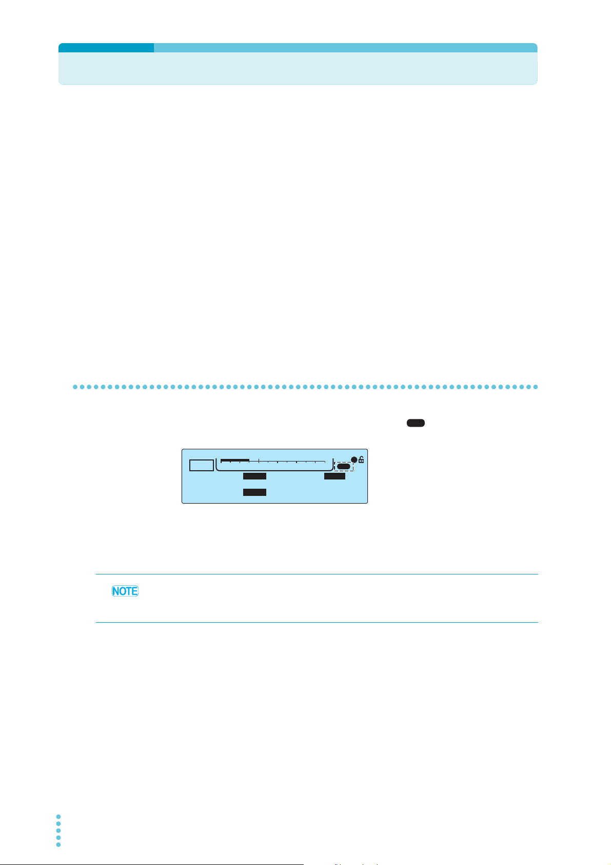
Remote Control Overview
USB
TIMER UPPER
LOWER
10.0
mA
0.01
mA
1.50
kV
60.0
s
ACW
1
USB
0
5.5kV
Voltage
In addition to using the front panel, the product can be controlled remotely through the USB
interface.
The remote interface complies with IEEE Std 488.2-1992 and SCPI Specification 1999.0.
■ Measuring instrument interface standards
The TOS5300 Series complies with the following standards.
• IEEE Std 488.2-1992 IEEE Standard Codes, Formats, Protocols, and Common Commands For
Use With IEEE Std 488.1-1987
• IEEE Std 488.1-1987 IEEE Standard Digital Interface for Programmable Instrumentation
• IEEE Std 1174-2000 IEEE Standard Serial Interface for Programmable Instrumentation
• Standard Commands for Programmable Instruments (SCPI) version 1999.0
• Universal Serial Bus Specification Rev 2.0
• Universal Serial Bus Test and Measurement Class Specification (USBTMC) Rev 1.0
• Universal Serial Bus Test and Measurement Class, Subclass USB488 Specification (USBTMC-
USB488) Rev 1.0
Using the USB Interface
When the product is being controlled remotely, the USB icon ( ) appears on the front-panel
screen. To use the front panel to switch the product back to local mode, press LOCAL.
To use the USB interface to control the TOS5300 Series, a driver that supports the USB Test &
Measurement class (USBTMC) must be installed on the controller.
The USBTMC driver is installed automatically by the VISA library.
Noise may be generated by problems such as the outputs being shorted or the DUT insulation
being damaged. This noise may cause errors in the remote control communication. To reduce the
effect of noise, keep the USB cable at least 30 cm away from the test leads and the DUT.
USB feature
• Complies with USB specification 2.0
• Complies with USBTMC specification 1.0 and USBTMC-USB488 specification 1.0
• Baud rate: 12 Mbps maximum (full speed)
• VID (vendor ID): 0x0B3E
• PID (product ID): 0x1017
Service request
The TOS5300 Series is equipped with service request and serial polling functions.
6 TOS5300_INTERFACE

Installing the VISA library
VISA (Virtual Instrument Software Architecture) is a specification for standard software that is used
to connect instruments. VISA was defined by the IVI Foundation.
A VISA library is required to use the software application. The VISA library (NI-VISA, Keysight VISA, or
KI-VISA) must be installed on the controller (Windows).
One of the VISA libraries (driver software implemented in compliance with the VISA specifications)
below is necessary.
• NI-VISA by National Instruments (Ver. 5.1.1 or later)
• Keysight VISA by Keysight Technologies (Keysight IO Libraries Suite 16.0 or later)
• KI-VISA Ver. 5.0.4 or later
• Do not install multiple VISA libraries on the same PC. Doing so may cause errors.
• If NI-VISA or Keysight VISA is already installed on your PC, you do not need to install
KI-VISA.
KI-VISA is an original VISA library developed by Kikusui Electronics Corporation that supports the IVI
VISA specifications 5.0. You can download the most recent version of this library from the Kikusui
Electronics Corporation website (https://www.kikusui.co.jp/en/ download/).
Remote Control Overview
1
Remote Control
TOS5300_INTERFACE 7

8 TOS5300_INTERFACE
This page is intentionally blank.

Remote Control
Message Overview
This chapter gives an overview of remote
control messages. It then explains topics such
as the make-up of the SCPI commands that
are used for remote control and the
command syntax.

Message Overview
The information that is transferred between the controller (the PC) and the TOS5300 Series is
referred to as “messages.”
The TOS5300 Series uses the SCPI language for these messages.
The messages that the PC sends to the TOS5300 Series are commands. The messages that the
TOS5300 Series sends to the PC are responses.
Commands are used to execute functions or change settings on the TOS5300 Series or to query its
settings or status. Responses are used to return the product’s settings or status.
SCPI command syntax
Command hierarchy
SCPI is an ASCII-based command language that was designed for test and measuring equipment.
The command structure is composed of the common roots and nodes that are the building blocks
of the SCPI subsystem. A command consists of a program header, parameters, and punctuation
marks.
The following table uses the SYSTem subsystem as an example to explain the hierarchy.
Program header Parameter Node level
:SYSTem Root node
:CONFigure 2nd level
:BEEPer 2nd level
:VOLume 3rd level
:FAIL <numeric> 4th level
:PASS <numeric> 4th level
:DATE <nr1>, <nr1>, <nr1> 2nd level
:ERRor 2nd level
[:NEXT] <code>, “<description>” 3rd level
• A colon (:) separates a higher node from a lower node.
Command syntax
In this manual, SCPI commands are expressed in the following format.
Example:
SYSTem:CONFigure:BEEPer:VOLume:PASS {<numeric>|MINimum|MAXimu
m}
• SCPI commands can be written in long form (with all the characters) or in short form (omitting
the lowercase characters).
SCPI commands can be transmitted in either long form or short form.
• SCPI commands are not case sensitive. VOLT, Volt, and volt are all received as the short form of
the VOLTage command.
VOLUME, Volume, and volume are all received as the long form of the VOLume command.
• A space separates a program header and its parameters.
• Multiple parameters are separated by commas.
• Compound commands can be created by concatenating two commands with a semicolon.
10 TOS5300_INTERFACE

Message Overview
Example:
SYSTem:CONFigure:BEEPer:VOLume:FAIL MINimum;PASS MINimum
This compound command sends the same commands as the two following commands.
SYSTem:CONFigure:BEEPer:VOLume:FAIL MINimum
SYSTem:CONFigure:BEEPer:VOLume:PASS MINimum
In the first command (SYSTem:CONFigure:BEEPer:VOLume:FAIL), SYSTem:CONFigure:BEEPer:
VOLume is set as the path. Therefore, in the second command, SYSTem:CONFigure:BEEPer:VOLume
can be omitted.
If you specify a node that is not defined in the current path (except for FAIL and PASS), an error will
occur.
• Program headers are separated by colons.
• By using colons and semicolons, you can concatenate commands of different subsystems.
Example:
SENSe:JUDGment MINimum;:SOURce:VOLTage?
There are two root nodes in this compound command: SENSe and SOURce.
When the second command or later begins with a colon, the path that was specified by the
previous command is cleared.
• The maximum length of a command that you can transmit on a single line is 128 bytes.
2
Message Overview
Special symbols and characters
The special symbols and characters that are used in this manual for the SCPI command syntax are
explained below.
Symbol or character Description
< >
{ }
[ ]
Character strings inside the < and > symbols indicate program data.
Do not include the < and > symbols in the actual program.
Characters and numbers delimited by “|” inside the { and } symbols indicate that
one of the delimited items is to be selected.Do not include the { and } symbols in
the actual program.
Character strings inside [ and ] indicate optional data.
When optional data is not sent with the program, the default value is sent. Do not
include the [ and ] symbols in the actual program.
Queries
You can query the settings and status of the TOS5300 Series.
To make a query, append a question mark to the end of the program header section. If the query
has parameters, insert a space after the question mark, and then write the parameters.
Example:
VOLTage? MINimum
If you want to send two queries on separate lines, send the second query after you have received
the response to the first one. If you send query commands on two lines at the same time, you may
receive an incomplete response.
TOS5300_INTERFACE 11

Message Overview
See
Terminating character strings
All commands must be terminated with a valid terminator.
The available terminators are <line feed> (ASCII 0x0A) and EOI (end-or-identify).
You can use either of these terminators to terminate a command.
When you terminate a command string, the path is reset to the root level.
CR (ASCII 0x0D) is not a terminator.
Common commands
p. 17
Parameters
There are commands that are common to the IEEE-488.2 and SCPI standards for functions such as
resetting devices and performing self-diagnoses. These common commands start with an asterisk
(“*”). These commands may have one or multiple parameters.
The SCPI parameter format is derived from the program parameter format that is defined in IEEE
488.2.
The program data expression format that the TOS5300 Series uses is shown below.
Non-numeric parameters
The TOS5300 Series uses the following three parameter types.
Symbol or character Description
Used when a series of ASCII characters are requested.
Be sure to enclose strings in single or double quotation marks. The opening and
closing quotation marks must match (you cannot mix single and double quotation
String data
(String)
Character data
(Character)
Boolean data
(Boolean)
marks).
Example: PROGram:NAME "ACW2IR"
If you want to include a quotation mark as part of the string, enter consecutive
quotation marks (with no characters between them). ASCII codes 20H to 7EH can be
used in strings.
Used when only a limited number of values are available for a program setting.
Responses are returned in short form.
Example: TRIGger:SOURce {IMMediate|BUS|TIMer|TEST}
Used to express a condition of 1 or 0, or ON or OFF.
Responses are returned as 1 or 0.
Example: SOURce:VOLTage:TIMer:STATe {ON|OFF|1|0}
12 TOS5300_INTERFACE

Numeric parameters
The TOS5300 Series uses the following five parameter types.
Message Overview
Symbol or
character
NR1
NR2
NR3
NRf NRf is a generic term that includes NR1, NR2, and NR3.
Numeric
1 Details are given in the “IEEE 488.2 Standard Digital Interface for Programmable Instrumentation.”
Description
Represents an integer value.
Represents a real number in floating-point format.
Represents a real number in scientific notation.
If 380 is returned in the response data, it is returned as +3.80000+E02. Five decimal places
are used.
Represents values such as the decimal point, optional prefixes, and measurement units.
Numbers are expressed the same as NRf.
MINimum and MAXimum are available as substitutes for declaring certain values.
You can also use units such as V, A, and S in numeric parameters.
If a value that cannot be assigned is entered, the TOS5300 Series rounds the value to the
closest possible value.
Example: SYSTem:CONFigure:BEEPer:VOLume:PASS 2.0
SYST:CONF:BEEP:VOL:PASS must be set to a value from 0.0 to 1.0, so even if you attempt to
set the value to 2.0, it will be set to 1.0.
1
1
1
Special form numeric parameters
The special form numeric parameters MINimum and MAXimum can be used as substitutes for the
actual maximum and minimum values when the parameter is numeric.
The following example sets the volume level of the buzzer that is sounded when a PASS judgment
occurs to the minimum value.
SYSTem:CONFigure:BEEPer:VOLume:PASS MINimum
You can query the minimum and maximum values for most parameters.
SOURce:VOLTage:PROTection? MAXimum
2
Message Overview
Measurement units
The default measurement units are listed below. Commands are accepted even if measurement
units are not specified.
• A (current) • V (voltage)
• OHM (resistance) • S (seconds
• HZ (frequency)
The following optional prefixes are supported. If you use optional prefixes, specify the
measurement unit.
• G (giga) • MA (mega)
• K (kilo) • M (milli)
• U (micro)
To enter “μ” in a parameter, use “U.” When the measurement unit is “Hz” or “OHM” and you enter
“M” in the parameter, the unit will be “mega.”
The unit symbols in the International System of Units contain lowercase characters. The IEEE
standard uses uppercase characters. SCPI commands are not case sensitive.
TOS5300_INTERFACE 13

14 TOS5300_INTERFACE
This page is intentionally blank.

Remote Control
Command Reference
This chapter explains topics such as
command details and registers.
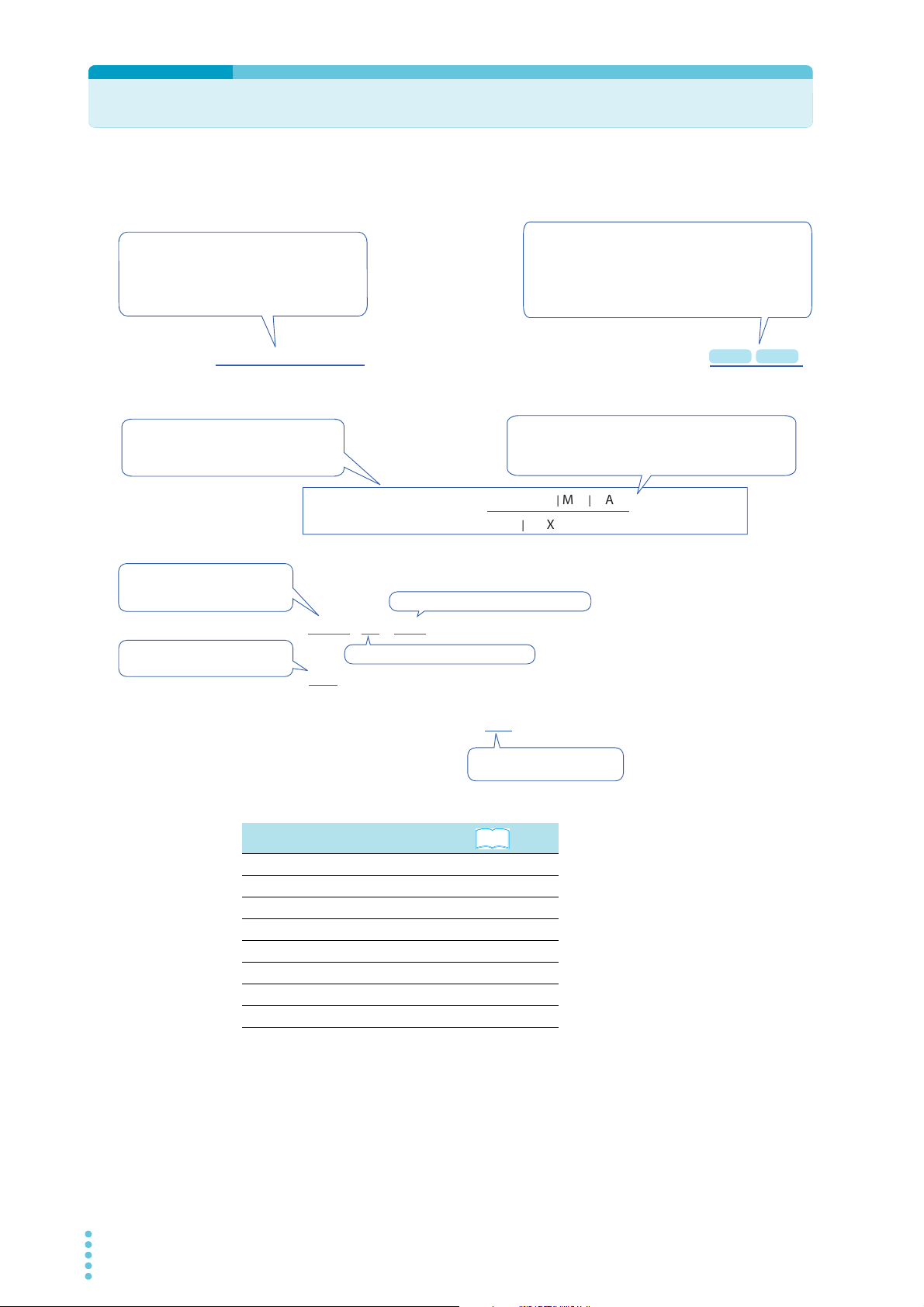
Command Description in This Manual
Append the value that you want to set the
setting to after the command.
To set the test voltage of a DC withstanding
voltage test (DCW) to 6.2 kV, send
SOUR:DCW:VOLT 6.2k.
Commands that have these marks are affected
when an *RST or *RCL command is sent. The
settings for the command are changed to the values
that are shown in the “Default values” section.
The test voltage is changed to 0 volts when the
*RST command is sent.
The commands are listed in the long form.
The lowercase characters can be omitted.
Sections that are enclosed in braces ([ ])
can also be omitted.
The setting range is listed.
Optional symbols such as m and μ
can also be used.
The unit for the value being set.
The unit can be omitted.
Specify MAX to set the maximum value.
Specify MIN to set the minimum value.
The format of the value that is
returned when a query is sent.
SOUR:DCW:VOLT
Sets the test voltage.
Command
SOURce:DCW:VOLTage[LEVel] {<numeric>|MIN|MAX}
SOURce:DCW:VOLTage[LEVel]? {MIN|MAX}
Parameter
Value:
0to6.2k
(The default value is 0.)
Unit:
V
Response Returns the test voltage in <NR3> format.
The parameters are listed.
In this command, the parameter is numeric. In addition to
specifying the desired value, you can specify the minimum
or maximum value.
* RCL* RST
See
In this manual, commands are described in the following manner.
References to command descriptions
Item
Command syntax p. 10
Parameters p. 12
Units p. 13
Queries p. 11
Expression format p. 12
List of messages p. 60
List of errors p. 66
Command processing time p. 71
16 TOS5300_INTERFACE

IEEE 488.2 Common Commands
*CLS
See
p. 46
IEEE 488.2-1992, section
10.3
Command *CLS
*ESE
See
p. 49
IEEE 488.2-1992, section
10.10
Command *ESE <NR1>
Parameter Value: 0 to 255
Clears all event registers including the status byte, event status, and error/event queue.
Sets the event status enable register that is counted by the event summary bit (ESB) of the status
byte.
*ESE?
An SCPI error (-222, “Data out of range”) occurs if the specified value is outside the
range.
3
Response Returns the value of the event status enable register in <NR1> format.
*ESR
See
p. 49
IEEE 488.2-1992, section
10.12
Command *ESR?
Response
*IDN
See
IEEE 488.2-1992, section
10.14
Example When *ESE 16 is transmitted, bit 4 of the event status enable register is set. Each time
the execution error bit (bit 4) of the event status register is set, the summary bit (ESB) of
the status byte is set.
Queries the event status register. Registers that are read are cleared.
Returns the value of the event status register in <NR1> format and clears the register.
Queries the model name, serial number, and firmware version of the TOS5300 Series.
Command Reference
Command *IDN?
Response
TOS5300_INTERFACE 17
The response to *IDN? is indicated below.
Example For a TOS5301 with serial number AB123456 and firmware version 1.00, *IDN? returns:
KIKUSUI,TOS5301,AB123456,1.00

IEEE 488.2 Common Commands
See
See
See
*OPC
Sets the OPC bit (bit 0) of the event status register when all the commands that are in standby have
IEEE 488.2-1992, section
10.18
Command *OPC
been processed.
*OPC?
Response
*OPT
Command *OPT?
Response
*PSC
IEEE 488.2-1992, section
10.25
Command *PSC <NR1>
Returns “1” when all the commands that are in standby have been processed.
Queries the options that are installed in the TOS5300 Series. This command performs the same
function as the SYSTem:OPTion? command.
Returns “0” if no options are installed. Returns one of the following responses in <character>
format if options are installed.
Returns “RC0X-TOS” if an RC01-TOS, RC02-TOS, HP01A-TOS, or HP02A-TOS option is installed.
Returns “SIGNAL I/O” if a SIGNAL I/O option is installed.
Example If the RC01-TOS is installed,
this command returns "RC0X-TOS."
Sets whether the event status enable register and service request enable register are
cleared when the POWER switch is turned on.
*PSC?
Parameter Value: 0 When the POWER switch is turned on, the *ESE and *SRE settings are not
cleared.
1 When the POWER switch is turned on, the *ESE and *SRE settings are
cleared.
An SCPI error (-222, “Data out of range”) occurs if the specified value is outside the
range.
Example To enable the power-on SRQ feature:
*PSC 0;*SRE 32;*ESE 128
Response Returns the power-on status setting in response to the PSC? query.
*RCL
Aborts the test execution (operation) and loads the settings that have been saved to memory.
p. 69
Command *RCL <NR1>
Parameter Value: 1 to 3 Memory number
For the commands that are affected by *RCL, see ”Default State”.
An SCPI error (-222, “Data out of range”) occurs if the specified value is outside the
range.
18 TOS5300_INTERFACE

*RST
See
See
p. 69
IEEE 488.2-1992, section
10.32
Command *RST
*SAV
See
p. 69
Command *SAV <NR1>
Parameter Value: 1 to 3 Memory number
IEEE 488.2 Common Commands
Aborts the test execution (operation) and resets the panel settings to their default values.
For the commands that are affected by *RST, see ”Default State.”
Saves the current settings to memory. The settings that are saved are the same as those that will be
loaded with the *RCL command. For details, see ”Default State.”
An SCPI error (-222, “Data out of range”) occurs if the specified value is outside the
range.
3
*SRE
IEEE 488.2-1992, section
10.34
Command *SRE <NR1>
Parameter Value: 0 to 255
Response Returns the value of the service request enable register in <NR1> format.
*STB
See
p. 48
IEEE 488.2-1992, section
10.36
Sets the service request enable register.
The service request enable register can be used to select which summary messages in the status
byte register will perform service requests.
To clear the service request enable register, send *SRE 0. If the register is cleared, service requests
cannot be generated using status information.
*SRE?
An SCPI error (-222, “Data out of range”) occurs if the specified value is outside the
range.
Example Sending *SRE 8 sets bit 3 of the service request enable register. Each time the summary
bit (bit 3) of the QUEStionable status register in the status byte is set, a service request
message is generated.
Queries the contents of the status byte register and the MSS (master summary status) message.
The response is the same as serial polling only with the exception that the MSS message appears in
place of the RQS message in bit 6.
Command Reference
Command *STB?
Response
TOS5300_INTERFACE 19
Returns the value of the status byte register and the MSS message (bit 6) in <NR1> format.

Test Mode Settings
See
See
See
5302
*TRG
IEEE 488.2-1992, section
10.37
Command *TRG
*TST
IEEE 488.2-1992, section
10.38
Command *TST?
Trigger command.
This is a substitute command for the IEEE 488.1 get message (Group Execute Trigger). If the
TOS5300 Series is in a state in which it does not accept triggers, an SCPI error (-211, “Trigger
ignored”) occurs.
Executes a self-test. You can query which error occurred by sending the SYST:ERR? command.
Response
Returns “0” if no errors are detected. Returns the error code if an error is detected.
*WAI
Prevents the TOS5300 Series from executing subsequent commands until all operations that are in
IEEE 488.2-1992, section
10.39
standby have been completed.
Command *WAI
Test Mode Settings
SOUR:FUNC:MODE
Sets the test mode. You can only set the test mode to one of the test modes that is available on your
model.
* RCL* RST
Command SOURce:FUNCtion:MODE {ACW|DCW|IR}
SOURce:FUNCtion:MODE?
Parameter Value: ACW AC withstanding voltage test (default)
DCW DC withstanding voltage test
IR Insulation resistance test
5301
Response Returns the test mode in <character> format.
20 TOS5300_INTERFACE

AC Withstanding Voltage Test (ACW) Conditions
* RCL* RST
* RCL* RST
These are commands for setting the AC withstanding voltage test conditions.
Measurement methods setting (ACW)
SENS:MODE
Sets the measurement method.
Command SENSe[:ACW]:MODE {RMS|AVE}
SENSe[:ACW]:MODE?
Parameter Value: RMS True rms response (default)
AVE Mean-value response
Response Returns the measurement method in <character> format.
Test voltage setting (ACW)
SOUR:VOLT
Sets the test voltage.
Command SOURce[:ACW]:VOLTage[:LEVel] {<numeric>|MIN|MAX}
SOURce[:ACW]:VOLTage[:LEVel]? {MIN|MAX}
* RST
3
Command Reference
Parameter Value: 0 to 5.5 k (The default value is 0.)
Unit: V
Response Returns the test voltage setting in <NR3> format.
Limit voltage setting (ACW)
SOUR:VOLT:PROT
Sets the limit voltage.
Command
Parameter Value: 0 to 5.5 k (The default value is 5.5 k.)
Response Returns the limit voltage in <NR3> format.
SOURce[:ACW]:VOLTage:PROTection[:LEVel][:UPPer] {<numeric>|MIN|MAX}
SOURce[:ACW]:VOLTage:PROTection[:LEVel][:UPPer]? {MIN|MAX}
Unit: V
TOS5300_INTERFACE 21

AC Withstanding Voltage Test (ACW) Conditions
Upper limit setting (ACW)
SENS:JUDG
Sets the upper limit that is used in judgments (UPPER).
Command SENSe[:ACW]:JUDGment[:UPPer] {<numeric>|MIN|MAX}
SENSe[:ACW]:JUDGment[:UPPer]? {MIN|MAX}
Parameter Value: 0.01 m to 110 m (The default value is 0.02 m.)
Unit: A
Response Returns the upper limit in <NR3> format.
Lower limit setting (ACW)
SENS:JUDG:LOW
Sets the lower limit that is used in judgments (LOWER). This setting is enabled when
SENS:JUDG:LOW:STAT is set to ON.
* RCL* RST
* RCL* RST
Command SENSe[:ACW]:JUDGment:LOWer {<numeric>|MIN|MAX}
SENSe[:ACW]:JUDGment:LOWer? {MIN|MAX}
Parameter Value: 0.01 m to 110 m (The default value is 0.01 m.)
Unit: A
Response Returns the lower limit in <NR3> format.
SENS:JUDG:LOW:STAT
Sets whether the lower limit is used in judgments (LOWER ON/OFF). Use SENS:JUDG:LOW to set the
lower limit.
Command SENSe[:ACW]:JUDGment:LOWer:STATe {ON|OFF|1|0}
SENSe[:ACW]:JUDGment:LOWer:STATe?
Parameter Value: ON (1) The limit is used in judgments.
OFF (0) The limit is not used in judgments (default).
Response Returns whether the lower limit is used in judgments in <NR1> format.
* RCL* RST
22 TOS5300_INTERFACE

Test time setting (ACW)
* RCL* RST
AC Withstanding Voltage Test (ACW) Conditions
SOUR:VOLT:TIM
Sets the test time (TIMER). This setting is enabled when SOUR:VOLT:TIM:STAT is set to ON.
Command SOURce[:ACW]:VOLTage:TIMer {<numeric>|MIN|MAX}
SOURce[:ACW]:VOLTage:TIMer? {MIN|MAX}
Parameter Value: 0.1 to 999.0 (The default value is 0.1.)
Unit: S
Response Returns the test time in <NR3> format.
SOUR:VOLT:TIM:STAT
Sets whether to stop testing after the set test time elapses (TIMER ON/OFF). Use SOUR:VOLT:TIM to
set the test time.
Command SOURce[:ACW]:VOLTage:TIMer:STATe {ON|OFF|1|0}
SOURce[:ACW]:VOLTage:TIMer:STATe?
Parameter Value: ON (1) Testing is stopped after the test time elapses (default).
OFF (0) Testing is not stopped after the test time elapses.
* RCL* RST
3
* RCL* RST
Command Reference
Response Returns whether testing is stopped after the test time elapses in <NR1> format.
Start voltage setting (ACW)
SOUR:VOLT:STAR:STAT
Sets whether the start voltage is used. The start voltage is 50 % of the test voltage.
Command SOURce[:ACW]:VOLTage:STARt:STATe {ON|OFF|1|0}
SOURce[:ACW]:VOLTage:STARt:STATe?
Parameter Value: ON (1) The start voltage is used.
OFF (0) The start voltage is not used.
Response Returns whether the start voltage is used in <NR1> format.
TOS5300_INTERFACE 23

AC Withstanding Voltage Test (ACW) Conditions
* RCL* RST
Voltage rise time setting (ACW)
SOUR:VOLT:SWE:TIM
Sets the voltage rise time (Rise Time).
Command SOURce[:ACW]:VOLTage:SWEep[:RISE]:TIMer {<numeric>|MIN|MAX}
SOURce[:ACW]:VOLTage:SWEep[:RISE]:TIMer? {MIN|MAX}
Parameter Value: 0.1 to 10.0 (The default value is 0.1.)
Unit: S
Response Returns the voltage rise time (Rise Time) in <NR3> format.
Voltage fall time setting (ACW)
SOUR:VOLT:SWE:FALL:TIM:STAT
Sets whether the voltage fall time (Fall Time) is used.
Command SOURce[:ACW]:VOLTage:SWEep:FALL:TIMer:STATe {ON|OFF|1|0}
SOURce[:ACW]:VOLTage:SWEep:FALL:TIMer:STATe?
* RCL* RST
Parameter Value: ON (1) The voltage fall time (Fall Time) is used.
OFF (0) The voltage fall time (Fall Time) is not used (default).
Response Returns whether the voltage fall time (Fall Time) is used in <NR1> format.
Test voltage frequency setting
SOUR:VOLT:FREQ
Sets the test voltage frequency.
Command SOURce[:ACW]:VOLTage:FREQuency {<numeric>|MIN|MAX}
SOURce[:ACW]:VOLTage:FREQuency? {MIN|MAX}
Parameter Value: 50, 60 (The default value is 50.)
Unit: HZ
Response Returns the test voltage frequency in <NR3> format.
* RCL* RST
24 TOS5300_INTERFACE
 Loading...