

Kikusui TOS5301, TOS5302, TOS5300 User Manual

General Description
Installation and
Preparation
Safety Precautions
during Testing
Panel Operation Basics
Withstanding Voltage and
Insulation Resistance Tests
External Control
Maintenance
Specifications
App
1
2
3
4
5
6
7
8
PART NO. IB025232
May. 2014
TOS5300
TOS5301
TOS5302
User’s Manual
Withstanding Voltage/
Insulation Resistance Tester
DANGER
This product generates high voltage!
,PSURSHURSHUDWLRQFDQOHDGWRVHULRXVDFFLGHQWV
7RSUHYHQWDFFLGHQWVEHVXUHWRUHDGWKHVHFWLRQ
³6DIHW\3UHFDXWLRQVGXULQJ7HVWLQJ´LQWKLVPDQXDO
.HHSWKLVPDQXDOFORVHWRWKHSURGXFWVRWKDWWKH
RSHUDWRUFDQUHDGLWDWDQ\WLPH

Thank you for purchasing the TOS5300 Series Withstanding
About the Operation Manuals
Voltage and Insulation Resistance Tester.
There are five TOS5300 Series Manuals listed as follows.
•Setup Guide
This manual is intended for first-time users of this product. It
provides an overview of the product and notes on usage. It also
explains how to set up the product for testing the DUT. Always
read this manual before using the product.
•Quick Reference
This manual explains Panel description and operation briefly.
•Safety Information
This document contains general safety precautions for this
product. Keep them in mind and make sure to observe them.
• User’s Manual (this manual)
This manual is intended for first-time users of this product. It
provides an overview of the product and notes on usage. It also
explains how to configure the product, operate the product,
perform maintenance on the product, and so on.
• Communication Interface Manual (PDF)
This manual contains details about remotely controlling the
tester using SCPI commands. This manual is provided on the
included CD-ROM.
The interface manual is written for readers with sufficient basic
knowledge of how to control measuring instruments using a
PC.
TOS5300 Series Manuals are intended for users of the
Withstanding Voltage and Insulation Resistance Tester and their
instructors. Explanations are given under the presumption that
the reader has knowledge about the electrical aspects of electrical
safety testing.
If you find any misplaced or missing pages in this manual, it will be
replaced. If the manual gets lost or soiled, a new copy can be
provided for a fee. In either case, please contact your Kikusui agent
or distributor, and provide the “Kikusui Part No.” given on the
cover.
Every effort has been made to ensure the accuracy of this manual.
However, if you have any questions, or find any errors or
omissions, please contact your Kikusui agent or distributor.
After you have finished reading this manual, store it so that you
can use it for reference at any time.
Waste Electrical and Electronic Equipment
(WEEE)
Disposing of used Kikusui products in the EU
Under a law adopted by member nations of
the European Union (EU), used electric and
electronic products carrying the symbol
below must be disposed of separately from
general household waste.
This includes the power cords and other
accessories bundled with the products. When
disposing of a product subject to these
regulations, please follow the guidance of your local authority, or
inquire with your Kikusui distributor/agent where you purchased
the product.
The symbol applies only to EU member nations.
Disposal outside the EU
When disposing of an electric or electronic product in a country
that is not an EU member, please contact your local authority and
ask for the correct method of disposal.
Trademarks
Microsoft, Windows, and Visual Basic are registered trademarks of
Microsoft Corporation in the United States and/or other countries.
All company names and product names used in this manual are
trademarks or registered trademarks of their respective
companies.
Copyrights
The contents of this manual may not be reproduced, in whole or in
part, without the prior consent of the copyright holder.
The specifications of this product and the contents of this manual
are subject to change without prior notice.
© 2010 Kikusui Electronics Corporation
Product firmware versions
This manual applies to products with ROM versions 1.2X.
When contacting us about the product, please provide us with:
• The model (marked in the top section of the front panel)
• The ROM version (see page 24)
• The serial number (marked in the bottom section of the rear
panel)
2 TOS5300

Notes to the supervisor
• If the operators cannot understand the language used in this manual, translate the manual
into the appropriate language.
• Make sure that the operators understand the information in this manual before they
operate this product.
• Keep this manual close to the product so that the operators can read the manual at any
time.
• If the tester will be used to repeatedly perform tests with fixed conditions, such as when
being used as part of a manufacturing line, attach the protection cover to ensure safe
operation of the tester. This is useful in preventing incorrect operation of the tester.
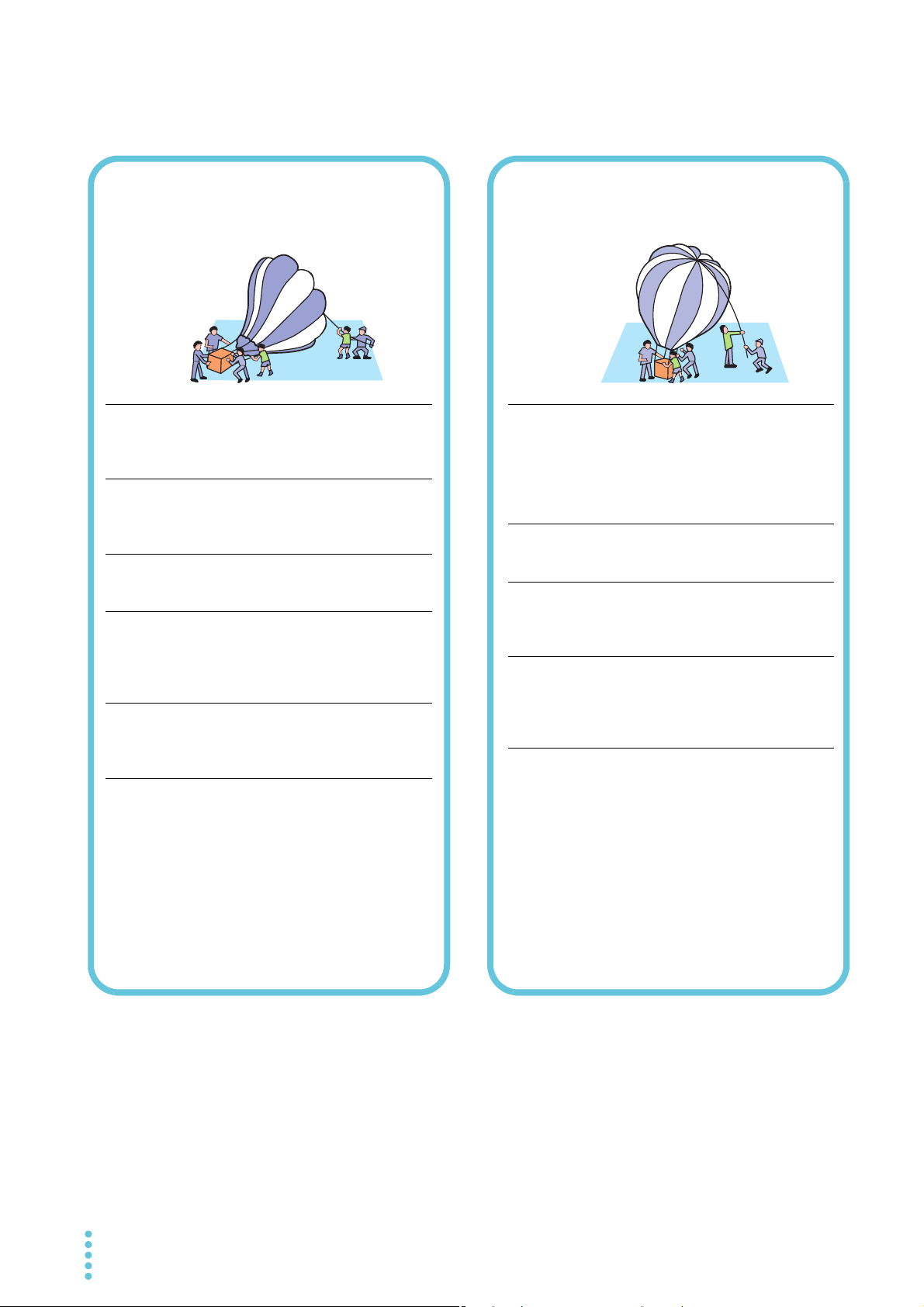
You will receive a potentially fatal electric shock if:
• You touch an output terminal while output is being generated.
• You touch a test lead that is connected to an output terminal while output is being
generated.
• You touch the device under Test (DUT) while output is being generated.
• You touch a location that is electrically connected to an output terminal while output is
being generated.
• You touch a location that is electrically connected to an output terminal immediately after
output is turned off after an insulation resistance test has been performed.
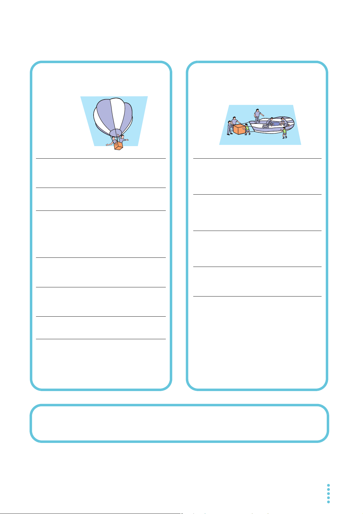
You may receive a potentially fatal electric shock if:
• You operate the tester without grounding it.
• You operate the tester without using rubber gloves for electrical work.
• You come close to a location that is electrically connected to an output terminal while
output is being generated.
• You come close to a location that is electrically connected to an output terminal
immediately after output is turned off after an insulation resistance test has been
performed.
Dangerous operations
TOS5300 3
When using this product, be sure to observe the “Safety
Safety Precautions
Precautions Concerning
Installation Location
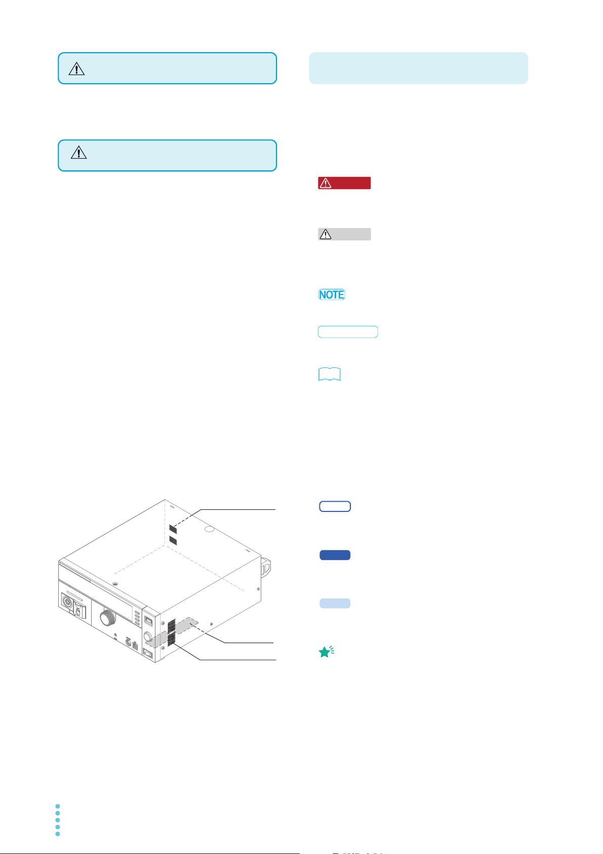
Rear panel inlet holes
Bottom panel
inlet holes
Right panel inlet holes
Notations Used in This Manual
WARNING
5300
5301
Memo
Precautions” in the Safety information manual.
When installing this product, be sure to observe the
“Precautions Concerning Installation Location” in the Safety
information manual. The following precautions pertain only
to this product.
• When installing this product, be sure to observe the
temperature and humidity ranges indicated below.
Operating temperature range: 0 °C to +40 °C
(32 °F to 104 °F)
Operating humidity range: 20 %rh to 80 %rh
(no condensation)
• When storing this product, be sure to observe the temperature
and humidity ranges indicated below.
Storage temperature range: -20°C to +70°C (-4°F to 158°F)
Storage humidity range: 90 %rh or less (no condensation)
• Do not use the product in a poorly ventilated location.
The product uses forced air cooling. It sucks air into the inlet
holes on its right, rear, and bottom panels, and then expels air
through its rear panel. Secure adequate space around the
product’s inlet and outlet holes to prevent the possibility of fire
caused by accumulation of heat.
Allow at least 20 cm of space between the inlet and outlet holes
on the side and rear panels and the walls (or obstacles).
Paper, vinyl, or any other product that may be easily sucked into
the inlet holes must not be placed between the inlet holes on
the bottom panel and the floor or stand that the product is
installed on.
Hot air (approximately 20 °C or 68 °F hotter than the ambient
temperature) is expelled from the outlet hole. Do not place
objects that are affected by heat near the air outlet.
• The TOS5300 Series Withstanding Voltage and Insulation
Resistance Tester is also referred to as the TOS5300 Series.
• Device under test is also referred to as DUT.
• The term “PC” is used to refer generally to both personal
computers and workstations.
•The following markings are used in the explanations in the text.
Indicates a potentially hazardous situation which, if
ignored, could result in death or serious injury.
CAUTION
Indicates a potentially hazardous situation which, if
ignored, may result in damage to the product or other
property.
Indicates information that you should know.
DESCRIPTION
Explanation of terminology or operation principle.
See
Indicates a reference to detailed information.
SHIFT+key name (blue letters)
Indicates an operation that requires you to press a key
indicated in blue letters while holding down the SHIFT key.
SHIFT+MEMORY x (MEMORY 1 to MEMORY 3)
Indicates an operation that requires you to press a memory
key (MEMORY 1 to MEMORY 3) while holding down the SHIFT
key.
• Do not use the product near highly sensitive measuring
instruments or receivers.
The noise generated by the product may affect these other
devices. At a test voltage of 3 kV or greater, the product may
produce corona discharge between its test lead clips. This will
generate a significant amount of broadband RF emission. To
minimize this effect, keep the alligator clips away from each
other. Also, keep the alligator clips and test leads away from
conducting surfaces, especially sharp metal edges.
Indicates a feature or message that is only available on the
TOS5300 model.
Indicates a feature or message that is only available on the
TOS5301 model.
5302
Indicates a feature or message that is only available on the
TOS5302 model.
Indicates useful information.
4 TOS5300

Contents
1
2
About the Operation Manuals ................................................................................................................2
Notes to the supervisor .............................................................................................................................3
Dangerous operations ...............................................................................................................................3
Safety Precautions ......................................................................................................................................4
Precautions Concerning Installation Location ......................................................... 4
Notations Used in This Manual ...............................................................................................................4
Search by Topic.............................................................................................................................................8
Front Panel ..................................................................................................................................................10
Rear Panel .................................................................................................................................................... 12
General Description
Product Overview........................................................................................................................................................... 14
Features....................................................................................................................................................... 14
Options............................................................................................................................................................................... 16
Installation and Preparation
Checking the Package Contents ............................................................................................................................... 20
Connecting the Power Cord ....................................................................................................................................... 21
Using the Protection Cover......................................................................................................................................... 22
Turning the Power On................................................................................................................................................... 23
Checking indicators and the status of the interlock feature.................................................... 23
Turning the POWER switch on ............................................................................................................ 24
Turning the POWER switch off ............................................................................................................ 25
Performing the zero adjustment before testing........................................................................... 25
Connecting to the Device under Test (DUT)......................................................................................................... 26
Using test leads......................................................................................................................................... 26
Using the optional high voltage test probe (model HP01A-TOS/HP02A-TOS)................. 28
Disconnecting test leads from the DUT........................................................................................... 28
3
Safety Precautions during Testing
Pre-Test Inspection......................................................................................................................................................... 30
Testing Precautions........................................................................................................................................................ 30
Remote Control Precautions....................................................................................................................................... 31
Precautions after Output Has Been Turned Off ................................................................................................... 31
Interrupting Testing or Operations.......................................................................................................................... 32
Emergency Measures .................................................................................................................................................... 32
Forbidden Actions.......................................................................................................................................................... 32
Turning the power on and off repeatedly ...................................................................................... 32
About Malfunctions ....................................................................................................................................................... 33
To Use the Product for a Long Time Free of Malfunctions .............................................................................. 33
TOS5300 5

4
5
Panel Operation Basics
Parts of the Screen .......................................................................................................................................................... 36
Panel Operations ............................................................................................................................................................. 38
Switching between screens.................................................................................................................. 38
Selecting settings ..................................................................................................................................... 39
Entering values.......................................................................................................................................... 39
Locking panel operations (key lock).................................................................................................. 40
Selecting the Test Mode ............................................................................................................................................... 41
Single test (ACW, DCW, or IR)............................................................................................................... 41
Auto test (AUTO TEST) ........................................................................................................................... 41
Panel Memory................................................................................................................................................................... 42
Saving test conditions ............................................................................................................................ 43
Recalling test conditions........................................................................................................................ 44
Withstanding Voltage and Insulation Resistance
Tests
About Judgment ............................................................................................................................................................. 46
Effectiveness of the upper and lower limits.................................................................................... 46
Invalid Settings................................................................................................................................................................. 46
Setting Withstanding Voltage Test Conditions.................................................................................................... 47
AC withstanding voltage test (ACW) settings................................................................................ 47
DC withstanding voltage test (DCW) settings ............................................................................... 48
Setting Insulation Resistance Test Conditions...................................................................................................... 49
Insulation resistance test (IR) settings............................................................................................... 49
Auto Test (AUTO TEST) ................................................................................................................................................. 50
Setting Other Test Conditions .................................................................................................................................... 51
Start voltage .............................................................................................................................................. 51
Voltage rise time ...................................................................................................................................... 52
Voltage fall time ....................................................................................................................................... 52
Frequency ................................................................................................................................................... 52
Current detection response speed ................................................................................................... 52
Judgment wait time (Wait Time) ....................................................................................................... 53
Selecting Measurement Method ............................................................................................................................... 54
Saving the Calibration Date......................................................................................................................................... 55
Setting Other Test Features......................................................................................................................................... 56
Double action feature............................................................................................................................. 56
Length of time to maintain a PASS judgment result................................................................... 56
Momentary feature.................................................................................................................................. 57
Fail mode feature...................................................................................................................................... 57
Buzzer volume ........................................................................................................................................... 57
Starting Testing................................................................................................................................................................ 58
To start testing........................................................................................................................................... 58
When testing starts.................................................................................................................................. 58
To change the voltage setting during testing ............................................................................... 59
If you cannot start testing ..................................................................................................................... 60
Stopping Testing ............................................................................................................................................................. 60
To stop testing........................................................................................................................................... 60
When testing finishes.............................................................................................................................. 61
To clear judgment results...................................................................................................................... 61
6 TOS5300

6
7
8
External Control
SIGNAL I/O Connector................................................................................................................................................... 64
SIGNAL I/O specifications...................................................................................................................... 64
Internal construction .............................................................................................................................. 66
Input signal usage example................................................................................................................. 66
Output signal usage example ............................................................................................................. 66
Starting Testing ............................................................................................................................................................... 67
Recalling Panel Memory and Test Modes.............................................................................................................. 67
Interlock Feature............................................................................................................................................................. 68
How to use the interlock feature........................................................................................................ 69
STATUS OUT Connector ............................................................................................................................................... 69
Maintenance
Pre-Test Inspection......................................................................................................................................................... 72
Inspection of test leads and the judgment feature..................................................................... 72
Time Settings and Calibration Management........................................................................................................ 73
Calibration .................................................................................................................................................. 74
Backup Battery Replacement ..................................................................................................................................... 74
Specifications
Withstanding voltage tester ................................................................................................................ 76
Insulation resistance test section....................................................................................................... 79
Other features ........................................................................................................................................... 81
Interfaces..................................................................................................................................................... 82
General......................................................................................................................................................... 83
Outline drawing........................................................................................................................................ 84
Appen
dix
A List of Default Settings ...........................................................................86
Initializing the TOS5300 Series............................................................................................................ 86
Default panel memory values ............................................................................................................. 87
B Configuration Settings ...........................................................................88
Test Mode and Buzzer settings........................................................................................................... 89
Status Signal Output settings.............................................................................................................. 90
Date and Time settings.......................................................................................................................... 91
Communication display items ............................................................................................................ 92
Information display items..................................................................................................................... 92
C Protective Features ................................................................................. 93
D Troubleshooting....................................................................................... 94
Index....................................................................... 97
TOS5300 7
Search by Topic
• What accessories are included in the
package?
→” Checking the Package Contents” p.20
• Before I start testing, I want to check that
the TOS5300 Series is operating safely.
→”Turning the Power On” p.23
• How do I use each of the two test leads?
→”Using test leads” p.26
• I want to check that measurements are
being performed correctly before I start
testing.
→”Pre-Test Inspection” p.72
• I want to know more about the interlock
feature.
→”Interlock Feature” p.68
Preparation
• Other than the basic settings that are set
from the panel, what test conditions can be
set?
→”Setting Other Test Conditions” p.51
→”Configuration Settings” p.88
• How are measured values judged?
→”Abo ut Jud gm ent ” p. 46
• How does the TOS5300 Series display the
judgment results?
→”When testing finishes” p.61
• How do I keep the TOS5300 Series in the
PASS state?
→”Length of time to maintain a PASS
judgment result”
p.56
Setup
8 TOS5300
• How do I save the current test conditions
and use them later?
→”Panel Memory” p.42
• How do I start tests with a greater level of safety?
→”Double action feature” p.56
• How do I prevent unintentional key
operations from changing the test
conditions?
→”Using the Protection Cover” p.22
→”Locking panel operations (key lock)” p.40
• How do I perform consecutive tests by
switching test modes between each test?
→”Auto Test (AUTO TEST)” p.50
• How do I control the TOS5300 Series by
applying external signals?
→”SIGNAL I/O Connector” p. 64
• How do I release the interlock feature?
→”Turning the Power On” p. 23
Operation
• How do I check that the test leads are not
damaged (for example, that they have no
breaks)?
→”Pre-Test Inspection” p.72
• How do I check when calibration was last
performed?
→”Time Settings and Calibration
Management”
p.73
• How do I change the next scheduled
calibration date?
→”Time Settings and Calibration
Management”
p.73
• How do I set the system clock?
→”Time Settings and Calibration
Management”
p.73
Maintenance
Troubleshooting
See ”Troubleshooting” on page 94.
TOS5300 9
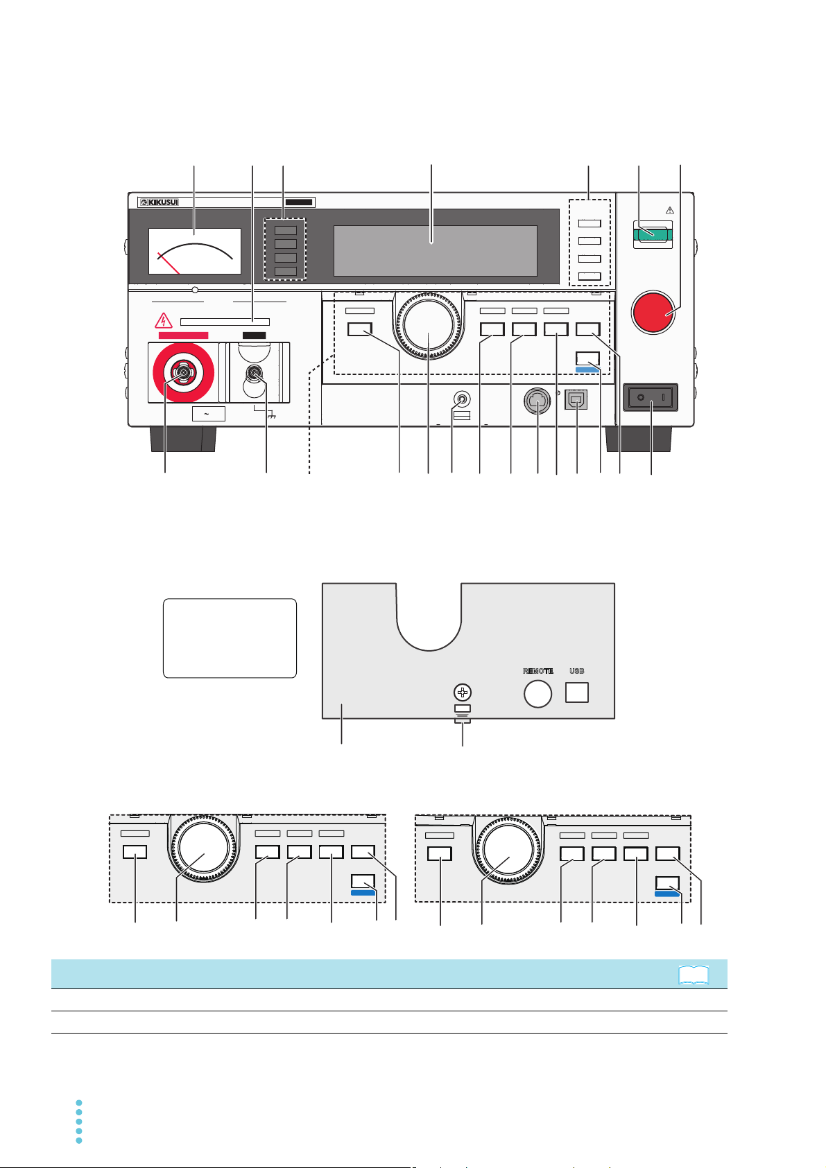
Front Panel
ACW /IR /AUTO
CUR/ RES
CONFIG LIMIT ON/ OFF ON/OFF KEY LOCK
FUNCTION
SET
VOLTA GE
UPR/LWR TEST
TIMER
MORE
LOCAL
SHIFT
LOCAL
SHIFT
START
STOP
1
MEMORY
2
3
RECALL
RESET
POWER
OUTPUT
DANGER
HIGH VOLTAGEHIGH VOLTAGE LOW
CONFIG LIMIT ON/ OFF ON/OFF KEY LOCK
FUNCTION
SET
VOLTAGE
UPR/LWR
CURRENT
R/T/F
TIMER
MORE
REMOTE USB
LOCAL
SHIFT
ACW
T
OS5
300
MAX5kV
ACW
AC WITHSTANDING
VOLTAGE TESTER
191816
14
10
11
13
191816
14
10
11
13
TOS5301 test conditions operating unit
TOS5300 front panel
TOS5302 test conditions operating unit
The protection cover
is attached to the
TOS5300 Series when
the product is shipped
from the factory.
19 201816
17
2
3
1
14
15
8
9
10
11
7
4
12513
6
Test conditions
operating unit
READY
TEST
PAS S
FAIL
21
Loosen the screw, and pull this part towards
you to remove the cover.
See
FUNCTION
ACW/ DCW
CONFIG LIMIT ON/ OFF ON/OFF KEY LOCK
VOLTAGE
SET
CURRENT
UPR/LWR
TIMER
TEST
MORE
No. Name Function
Analog voltmeter A voltmeter that indicates the output voltage. p.23
1
DANGER LED Lights in red when testing is being performed. p.58
2
10 TOS5300
No. Name Function
READY: Lights in light blue when the TOS5300 Series is ready to perform a test. p.58
Status indicators
3
TEST: Lights in red when testing is being performed. p.58
PASS: Lights in green when a test passes. p.61
FAIL: Lights in yellow when a test fails. p.61
Display Displays the settings, measured values, and other information. p.36
4
Press these keys to display the settings that are saved to memory.
When test conditions or configuration items are being set, these keys correspond to
the menus displayed on the screen.
MEMORY keys
5
MEMORY 1 key: Displays the settings saved to MEMORY 1.
MEMORY 2 key: Displays the settings saved to MEMORY 2.
MEMORY 3 key: Displays the settings saved to MEMORY 3.
RECALL key: Recalls settings from panel memory.
+ SHIFT key: Saves the current settings to panel memory.
START switch Starts testing. p.58 , p.78
6
STOP switch Stops testing and clears the current status. p.60
7
HIGH VOLTAGE
8
terminal
LOW VOLTAGE terminal This terminal is for the low line of the tester output (with cable lock). p.26
9
This terminal is for the high line of the tester output. p.2 6
1
Switches between test modes.
Function key
10
TOS5300: ACW key
TOS5301: ACW/ DCW key
TOS5302: ACW/ IR/ AUTO key
CONFIG key Displays the configuration setup screen. p.88
Rotary knob Changes settings. p.39
11
Screw hole Fasten a screw to this hole to fix the protection cover in place. —
12
SET key Press to select the voltage setting. p.39
13
LIMIT key Press to select the voltage limit setting. p.39
TOS5300/TOS5301: Press to select the upper and lower current limits.
UPR/ LWR key
14
TOS5302: Press to select the upper and lower current and resistance limits.
+SHIFT key: Turns the lower current limit on and off.
1
ON/ OFF key Turns the lower limit judgment feature on and off. p.39
REMOTE connector
15
Specialized connector for connecting the optional remote control box, RC01-TOS/
RC02-TOS, or the high voltage test probe, HP01A-TOS/HP02A-TOS.
TEST key Press to select the test time (Test Time). p.39
16
ON/ OFF key Turns the test time (Test Time) on and off. p.39
USB port This is the USB interface. —
17
LOCAL key Switches between local mode and remote mode. —
18
SHIFT key Used to access the features that are written in blue. —
Selects additional test condition settings.
ACW: Start voltage (Start Voltage), rise time (Rise Time), fall time (Fall Time), and
frequency (Frequency).
MORE key
19
DCW: Start voltage (Start Voltage), rise time (Rise Time), and the time to wait before
making judgments (Wait Time).
IR: The time to wait before making judgments (Wait Time) and current detection
response speed (Response).
KEY LOCK key Locks panel key operations (settings and changes). p.40
See
p.42 , p.88
p.38 , p.41 ,
p.47 , p.49 ,
p.50
p.39
p.16 , p.28
p.39 ,p.51
POWER switch
20
Protection cover Cover designed to prevent incorrect operation of the TOS5300 Series. p.22
21
1 This indicates an operation that requires you to press a key while holding down the SHIFT key.
TOS5300 11
Turns the power on [ ] and off [ ].
p.23
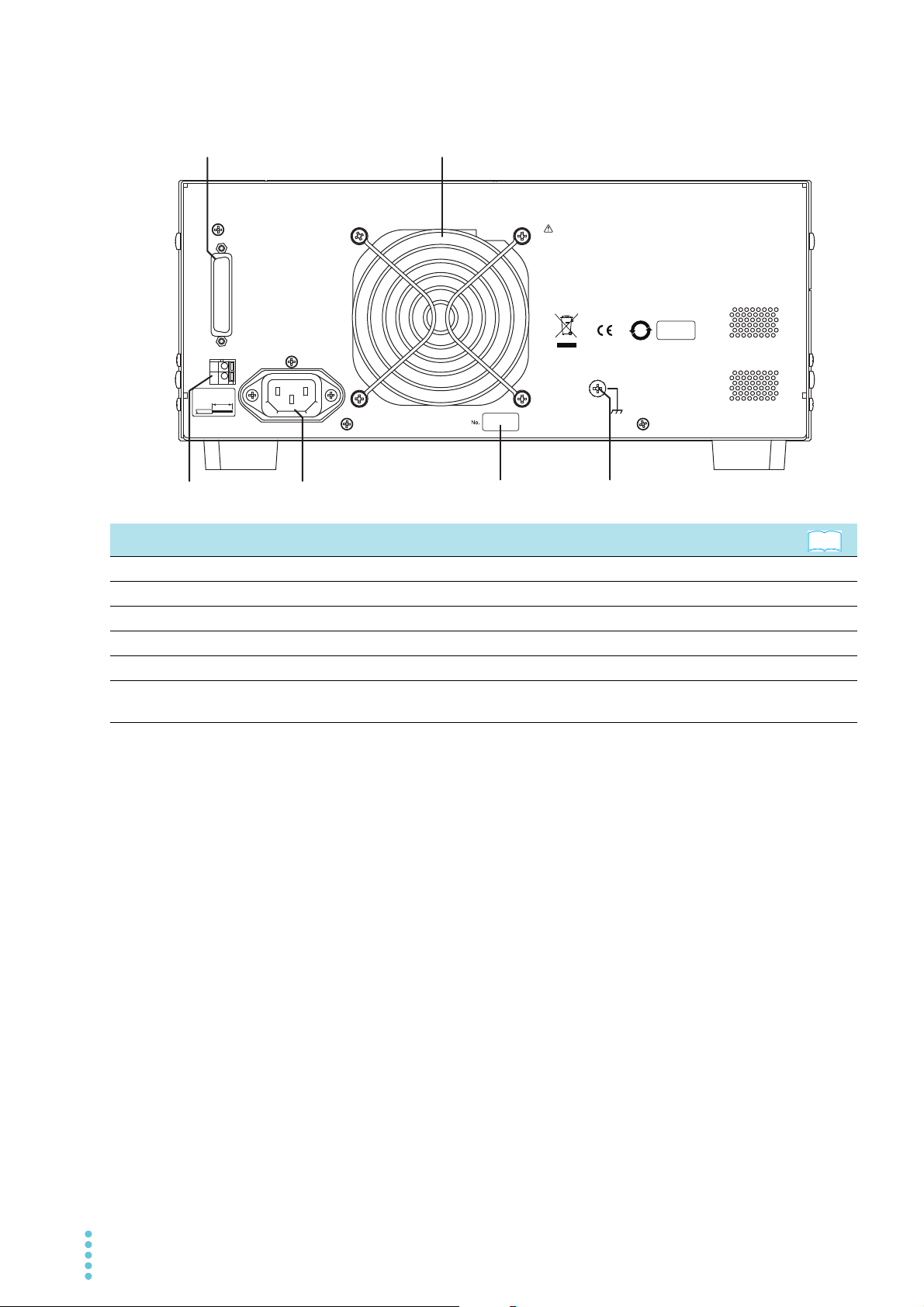
Rear Panel
SIGNAL
I/O
COM
STATUS
OUT
+
STRIP-GAUGE
AWG
24-16
10 mm
AC INPUT
50/60Hz
800VA MAX
100-240V
KIKUSUI ELECTRONICS CORP.
MADE IN TAIWAN
ᮏ〇ရ䛾䜹䝞䞊䛿䚸⤯ᑐ䛻ྲྀ䜚እ䛧䛶䛿䛔䛡䜎䛫䜣䚹
ෆ㒊䛾Ⅼ᳨䛿ᙜ♫䛜ㄆ䜑䛯䝃䞊䝡䝇䝬䞁䛻ጤク䛧䛶䛟䛰䛥䛔䚹
㟁※䝁䞊䝗ཬ䜃㈇Ⲵ⥺䛾ྲྀ䜚ᢅ䛔䛿䚸ᚲ䛪㟁※䝥䝷䜾䜢ᢤ䛔䛶
䛛䜙⾜䛳䛶䛟䛰䛥䛔䚹
DO NOT REMOVE COVERS. NO OPERATOR SERVICEABLE
PARTS INSIDE.
REFER SERVICING TO QUALIFIED SERVICE PERSONNEL.
UNPLUG THE MAINS SUPPLY CORD BEFORE HANDLING
THE CORD OR LOAD WIRES.
WARNING
㆙࿌
10
1 2
4
6
3
5
See
No. Name Function
SIGNAL I/O connector External control signal connector. p.64
1
Air outlet Vent for cooling the TOS5300 Series. —
2
STATUS OUT connector Connector for connecting the optional warning light unit, PL02-TOS. p.17 , p.69
3
AC LINE connector AC inlet. p.21
4
Serial number This is the serial number of the TOS5300 Series. —
5
Chassis terminal Terminal for grounding the product when it cannot be grounded through
6
the power cord.
—
12 TOS5300

General Description
This chapter gives an overview of the
TOS5300 Series and explains the options that
are available for it.

Product Overview
5302
The TOS5300 Series Withstanding Voltage and Insulation Resistance Testers perform withstanding
voltage and insulation resistance tests, which are two of the four tests that are required for ensuring
the safety of electrical products.
This product can perform withstanding voltage and insulation resistance tests on electrical
products and electrical components in accordance with the requirements of safety and electrical
standards and ordinances such as IEC, EN, UL, VDE, and JIS.
It is suited to (1) research and development installations, (2) test facilities for quality assurance
testing and standard certification, and (3) manufacturing lines.
The TOS5300 can perform AC withstanding voltage tests (ACW). The TOS5301 can perform AC
withstanding voltage tests and DC withstanding voltage tests (ACW and DCW). The TOS5302 can
perform AC withstanding voltage tests (ACW) and insulation resistance tests (IR).
These withstanding voltage and insulation resistance testers are easy to use, safe, and reliable.
Features
● Newly developed constant-voltage output for stable testing
The TOS5300 Series is not affected by AC line interference. Because the output voltage is
maintained at a fixed value even if the AC line voltage or frequency changes, stable tests can be
performed even in locations where the power supply is unstable.
The AC inlet is designed for worldwide use. The TOS5300 Series can be used without
modification provided the nominal power supply voltage is within the range of 100 VAC to 240
VAC (90 VAC to 250 VAC)
and the frequency is within the range of 47 Hz to 63 Hz.
1
● Rise time control feature that gradually increases the test voltage (only for withstanding
voltage tests)
Instead of immediately applying the specified test voltage to the DUT after the test begins, this
makes it possible to perform tests in which the voltage is raised gradually to the test voltage. As
required by withstanding voltage tests defined by standards such as IEC and UL, this makes it
possible to perform tests in which no more than half of the test voltage is applied at the start of
the test, and the test voltage is gradually reached over the specified time.
● Fall time control feature that gradually decreases the test voltage
The test voltage can be gradually decreased after a PASS judgment occurs during an AC
withstanding voltage test.
● Auto test (AUTO TEST) for performing consecutive tests
A combination of an AC withstanding voltage test and an insulation resistance test (IR) can be
performed in sequence.
● Calibration Protection feature that provides a notification when TOS5300 Series
calibration is required
The product displays a message when the preset calibration period elapses. It is also possible to
switch the product into protection mode and apply limits to its use when this period elapses.
1 The four tests are the withstanding-voltage, insulation-resistance, earth-continuity, and leakage-current
tests.
14 TOS5300

Product Overview
● Window comparator feature for setting upper and lower judgment limits
You can set not only the upper limit, but the lower limit as well. This is useful in determining
whether there are breaks in test leads or whether there was a mistake during operations. This
leads to highly reliable tests.
● Ability to save three sets of test conditions
Up to three sets of test conditions for single tests (AC withstanding voltage tests, DC
withstanding voltage tests, and insulation resistance tests) and auto tests (an insulation
resistance test followed by a withstanding voltage test and a withstanding voltage test
followed by an insulation resistance test) can be saved.
1
● Improved safety
In addition to having features that enable you to view the output voltage, the TOS5300 Series
also enables you to set the voltage limits, so you can prevent a voltage greater than what is
necessary from being generated unintentionally. This provides protection for the DUT.
● Standard-equipped USB port
The TOS5300 Series is standard-equipped with a USB interface. You can use a PC or sequencer
to control test conditions and read measured values and test results.
● Easier to read
The LED graphic display is easy to read. Additionally, when a protective feature is activated, the
reason for its activation is easily viewable on the display.
● Light-weight and easy to move
Even though the TOS5300 Series can generate 500 VA, which is sufficient for performing
withstanding voltage tests, it weighs at most 15 kg, so it can be moved by even a single person.
● Protection against incorrect operations
In addition to the key lock feature, the TOS5300 Series has a protection cover for the part of its
panel that is used to change test conditions. This cover is useful in preventing incorrect
operations when you want to perform tests with fixed conditions.
General Description
TOS5300 15
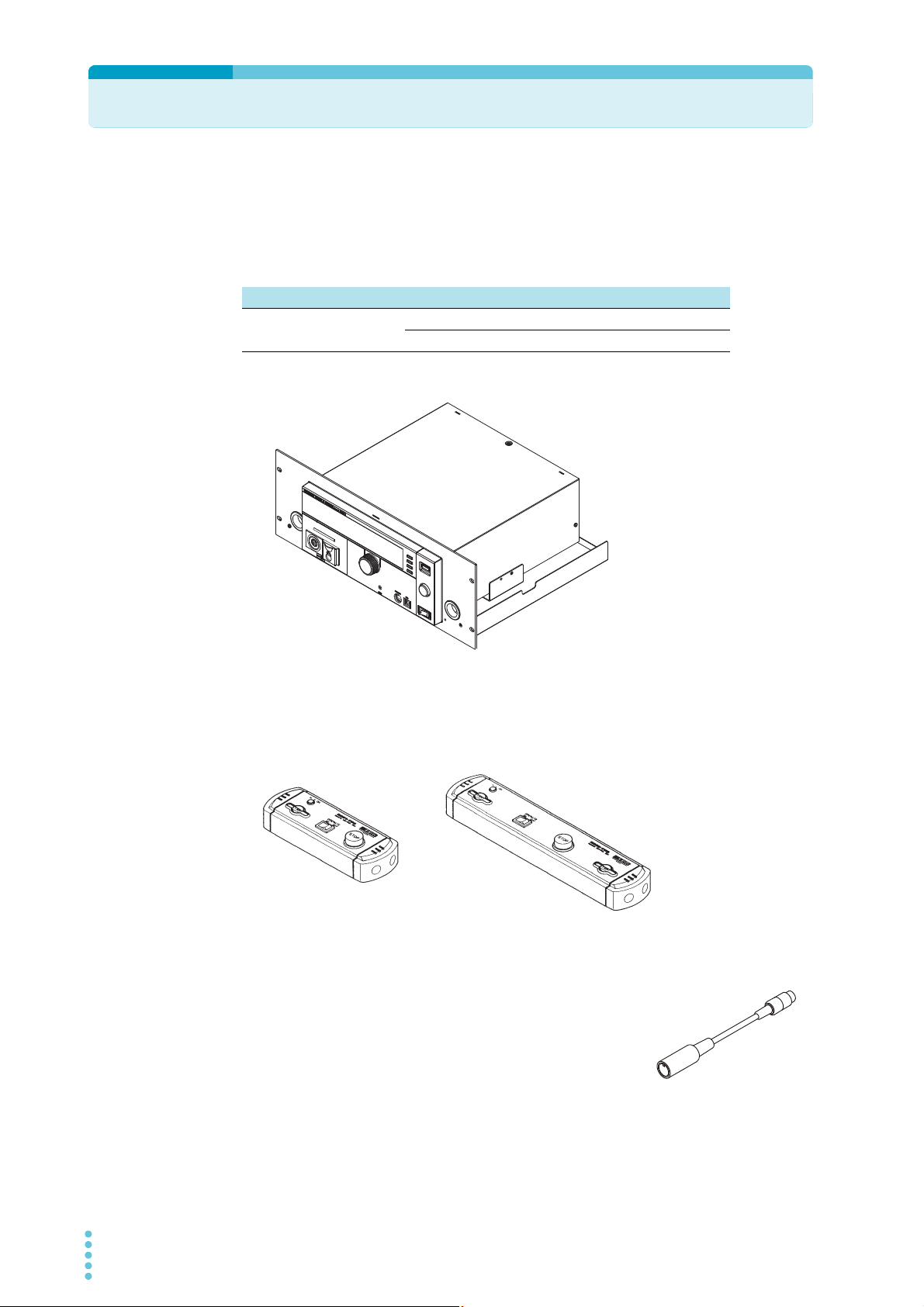
Options
RC01-TOS (one hand)
RC02-TOS (two hands)
Rack mount option
The following options are available for the TOS5300 Series.
For information about options, contact your Kikusui agent or distributor.
Name Model Notes
Rack mount adapter
KRA4-TOS For an EIA inch rack
KRA200-TOS For a JIS millimeter rack
KRA4-TOS
Model RC01-TOS/RC02-TOS remote control box
The remote control box can be used to start and stop withstanding voltage and insulation
resistance tests. One model is for use with one hand, and the other model is for use with two hands.
Model DD-5P/9P remote control adapter cable
This is an adapter cable for connecting the product to a remote
control box.
16 TOS5300

Model HP01A-TOS/HP02A-TOS high voltage test probe
Options
See
p.28
This is a probe for generating the test voltage. To prevent the test
voltage from being generated unintentionally, this probe has been
designed so that the test voltage is only generated when the user
operates the probe with both hands.
Model PL02-TOS warning light unit
The warning light unit indicates that the TOS5300 Series is
performing a test. This enables you to see that a test is in
progress from a distance.
1
General Description
TOS5300 17

18 TOS5300
This page is intentionally blank.

Installation and Preparation
This chapter describes how to unpack and
prepare this product before you use it.
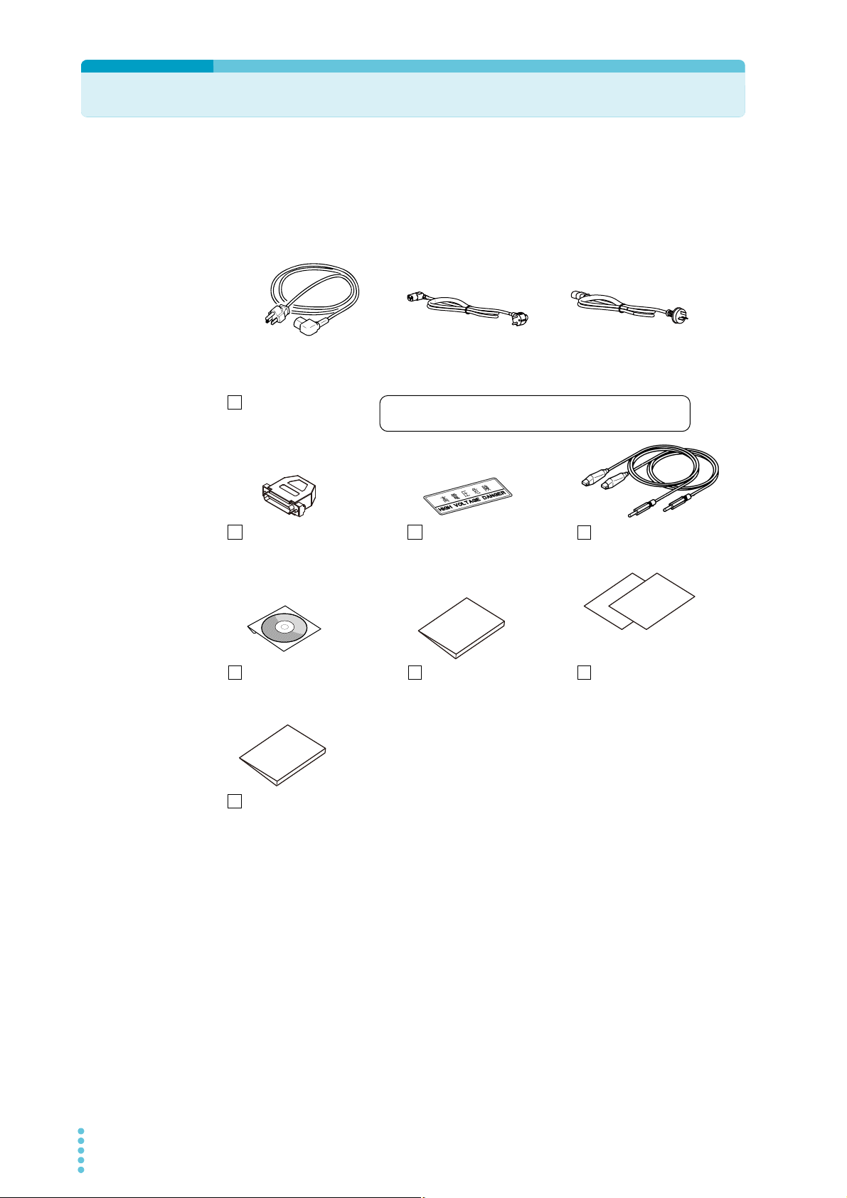
Checking the Package Contents
High-voltage test lead (1 set)
[TL31-TOS]
Setup guide (1 pc.)
[Z1-005-660]
Power cord (1 pc.)
SIGNAL I/O plug (1 set)
Assembly type
(D-sub plug unit)
High-voltage warning
sticker (1 pc.)
[A8-210-202]
CD-ROM (1 pc.)
[SA-6040]
Japanese: 1pc. [Z1-005-650]
English: 1pc. [Z1-005-652]
Quick Reference
Safety information (1pc.)
[Z1-005-040]
Rated voltage: 125 Vac
PLUG: NEMA5-15
[85-AA-0003]
[85-AA-0005]
Rated voltage: 250 Vac
PLUG: CEE7/7
[85-10-0790]
Rated voltage: 250 Vac
PLUG: GB1002
or
or
The power cord that is provided varies depending on
the destination for the product at the factory-shipment.
When you receive the product, check that all accessories are included and that the accessories have
not been damaged during transportation.
If any of the accessories are damaged or missing, contact your Kikusui agent or distributor.
We recommend that you save all packing materials, in case the product needs to be transported at
a later date.
20 TOS5300

Connecting the Power Cord
WARNING
• This product is a piece of equipment that conforms to IEC Safety Class I (equipment that
has a protective conductor terminal). Be sure to earth ground the product to prevent
electric shock.
• The product is grounded through the power cord ground wire. Connect the protective
conductor terminal to earth ground.
• Use the supplied power cord to connect to the AC line.
If the supplied power cord cannot be used because the rated voltage or the plug shape is
incompatible, have a qualified engineer replace it with an appropriate power cord that is 3 m or
less in length. If obtaining a power cord is difficult, contact your Kikusui agent or distributor.
• The power cord with a plug can be used to disconnect the product from the AC line in an
emergency. Connect the plug to an easily accessible power outlet so that the plug can be
removed from the outlet at any time. Be sure to provide adequate clearance around the power
outlet.
• Do not use the supplied power cord for other devices.
This product is a piece of equipment that conforms to IEC Overvoltage Category II (energyconsuming equipment that is supplied from a fixed installation).
In addition to the supplied power cord, Kikusui also provides other 200 V power cords with plugs
(sold separately).
2
Installation and Preparation
Check that the POWER switch is turned off.
1
Check whether the AC power line is compatible with the input rating of the
2
product.
The product can receive a nominal power supply voltage in the range of 100 VAC to
240 VAC (90 VAC to 250 VAC) that has a frequency in the range of 47 Hz to 63 Hz.
Connect the power cord to the rear-panel AC inlet, and then connect the
3
power plug to an outlet that has a ground terminal.
TOS5300 21
Using the Protection Cover
OUTPUT
CONFIG LIMIT ON/OFF ON/OFF KEY LOCK
SET
VOLTAGE
UPR/LWR
CURRENT
R/T/F
TIMER
LOCAL
SSHIFT
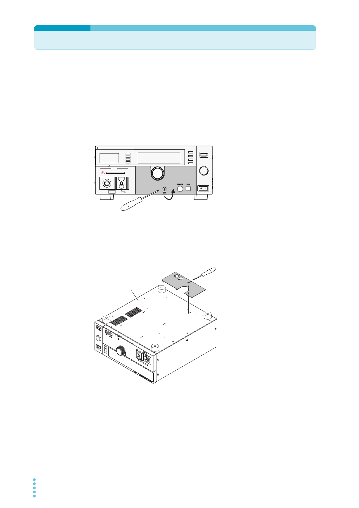
Loosen the screw.
Pull the cover toward you.
TOS5300 Series
bottom panel
Use the screw to fasten
the cover in place.
When the product is shipped from the factory, a protection cover is attached to the front panel. This
cover prevents unintentional changes to the test conditions. Remove this cover when you want to
set the test conditions.
Even when the cover is attached, you can still recall settings from memory, start and stop tests,
perform remote operations, and control the TOS5300 Series through its USB port. If the tester will
be used to repeatedly perform tests with fixed conditions, such as when being used as part of a
manufacturing line, attach the protection cover to ensure safe operation of the tester. This is useful
in preventing incorrect operation of the tester.
If the cover is damaged or lost, contact your Kikusui agent or distributor.
■ Removing the protection cover
Loosen the screw, and then pull the
hook centered at the bottom of the
cover towards you to remove the
protection cover from the panel.
■ Attaching the protection cover
Insert the tabs at the top of the cover into the slots in the panel, push the bottom part of the cover
until it is attached to the panel, and then use the screw to fix the cover in place.
■ Storing the protection cover
When you want to use the
TOS5300 Series without the
protection cover attached,
such as when you will
repeatedly perform tests
with frequently changed
test conditions, you can
store the protection cover
on the product’s bottom
panel. This is useful in
preventing the cover from
being lost.
Use the screw to fix the
cover to the product’s
bottom panel.
22 TOS5300
Turning the Power On
See
OUTPUT
DANGER
T
OS5
300
ACW
AC WITHSTANDING
VOLTAGE TESTER
0
Zero indication
TOS5302 WITHSTANDING VOLTAGE /
INSULATION RESISTANCE TESTER
Version 1.00
KIKUSUI ELECTRONICS CORP.
TIMER UPPER
LOWER
0.02
mA
0.01
mA
0.50
kV
10
.5
s
ACW
InterLock Protection
(Code:0x0001)
!
PROTECTION
Firmware version screen
Interlock protection mode
Checking indicators and the status of the interlock feature
See
See
p.68
p.68
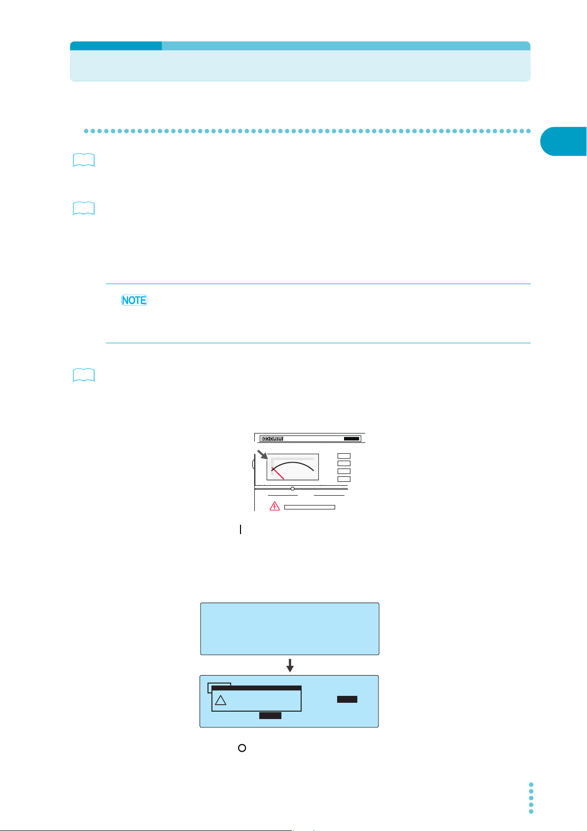
The first time that you turn the POWER switch on after you purchase the TOS5300 Series, the tester
will be in PROTECTION mode through the interlock feature. Connect the included SIGNAL I/O plug
to the SIGNAL I/O connector to release the interlock feature.
Only use the included SIGNAL I/O plug to easily release the PROTECTION mode.
When you are actually performing tests, use the interlock feature to ensure safety.
During withstanding voltage and insulation resistance tests in which you are using tools, (1) placing
a cover over the DUT so that output is turned off whenever the cover is removed to prevent electric
shock and (2) placing a safety fence around the work area where withstanding voltage and
insulation resistance tests are being performed so that output is turned off whenever the fence is
opened are both examples of effective safety measures.
When the TOS5300 Series is turned on, a self-test is run, and all the indicators on the front panel
light. To ensure safety, check that all the indicators light before you use the TOS5300 Series. It is
especially dangerous to use the tester if its DANGER LED is broken.
When the power is turned on, the DANGER LED lights, but no voltage is generated.
2
Installation and Preparation
p.21
Check that the power cord and all cables are correctly connected.
1
Check that nothing is connected to the SIGNAL I/O connector.
2
Check that the analog voltmeter is indicating “0.”
3
Press the ( ) side of the front-panel POWER switch to turn the TOS5300 Series
4
on.
Check that all the front-panel indicators light.
The firmware version screen will be displayed for a few seconds, and then a message
indicating that the TOS5300 Series is in PROTECTION mode will be displayed.
Check that the tester is in PROTECTION mode through the interlock feature.
TOS5300 23
Press the ( ) side of the front-panel POWER switch to turn the TOS5300 Series
5
off.
Turning the Power On
T
OS5
300
ACW
AC WITHSTANDING
VOLTAGE TESTER
0
Zero indication
READY
TIMER UPPER
LOWER
0.02
mA
0.01
mA
0.50
kV
10
.5
s
ACW
See
TIMER UPPER
LOWER
0.02
mA
OFF
0.00
kV
0
.3
s
ACW
TIMER UPPER
LOWER
10.0
mA
0.01
mA
1.50
kV
60.0
s
ACW
UPPER
Calibration Protection
(Code:0x0002)
!
PROTECTION
See
Turning the POWER switch on
Connect the included SIGNAL I/O plug to the SIGNAL I/O connector.
1
Connecting the SIGNAL I/O plug will release the interlock feature.
Check that the analog voltmeter is indicating “0.”
2
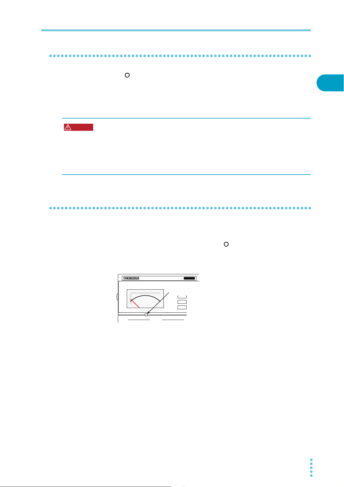
Turn the POWER switch on ( ).
3
Check the firmware version (Ver x.xx) that is displayed on the screen.
4
Check that the firmware version screen is displayed for a few seconds, that the setup
screen for setting the AC withstanding voltage test conditions is displayed thereafter,
and that the tester is then in READY mode (that the READY LED lights).
p.86
Check that the analog voltmeter is indicating “0.”
5
The first time that the POWER switch is turned on, the firmware version is displayed, and then the
setup screen for setting the AC withstanding voltage test conditions is displayed (with the factory
default settings).
The product stores the settings that are in use before it is turned off, so the next time that the
POWER switch is turned on, the TOS5300 Series starts with these settings.
About the system clock
The TOS5300 Series keeps track of the scheduled calibration date by using the internal system
clock. When the tester is turned on after the previously set calibration period has elapsed, a
message alerting you of this fact is displayed.
p.73
24 TOS5300
For details on how to set the system clock and what to do when the calibration period has elapsed,
see ”Time Settings and Calibration Management.”
Turning the POWER switch off
WARNING
OUTPUT
T
OS5
300
ACW
AC WITHSTANDING
VOLTAGE TESTER
0
Analog voltmeter’s zero adjuster
Use a flat-blade screwdriver or other
fine-tipped tool to turn the adjuster.
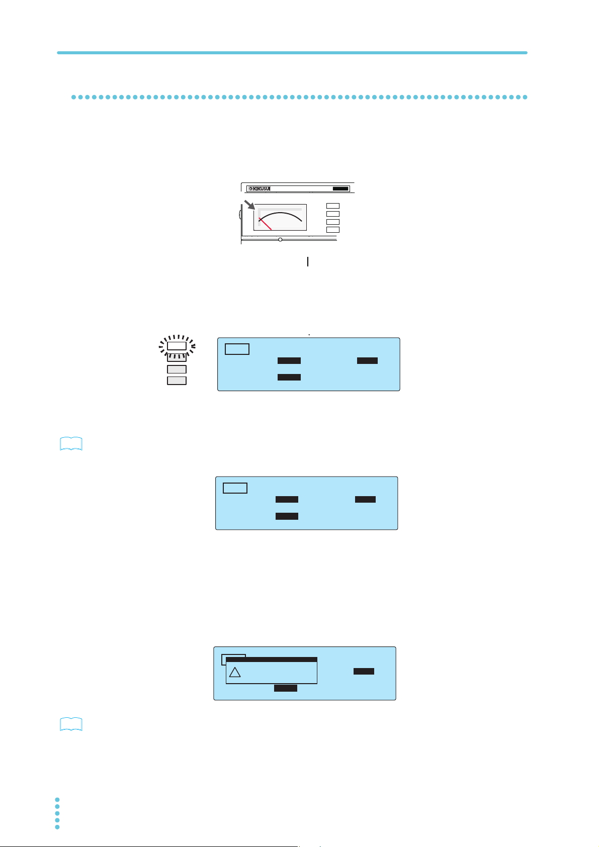
Press the ( ) side of the POWER switch to turn the TOS5300 Series off.
Turning the Power On
The panel settings that were in use immediately before the POWER switch was turned off are saved.
If the POWER switch is turned off immediately after the settings have been changed, the last
settings may not be stored.
Possible electric shock.
• After you turn the POWER switch off, wait at least 10 seconds before you turn the POWER
switch back on. It is dangerous to do otherwise, because the protective features of the
product may not work effectively.
This may cause the product to malfunction, and it may reduce the life of the POWER switch
and internal parts such as the fuses.
• Except in an emergency, do not turn the POWER switch off while output is being generated.
Performing the zero adjustment before testing
If the analog voltmeter does not indicate “0,” perform this adjustment.
Check that the POWER switch is turned off ( ).
1
Use the analog voltmeter’s zero adjuster to set the needle to the correct
2
position.
2
Installation and Preparation
TOS5300 25
Connecting to the Device under Test (DUT)
WARNING
WARNING
CAUTION
Never touch these parts during testing.
Plate designed to prevent
incorrect connections
See
LOW test lead (black)
Raise the cable lock.
Possible electric shock. During testing (while the TEST LED or DANGER LED is lit), never
touch the HIGH VOLTAGE terminal, test leads, and DUT.
Using test leads
Possible electric shock.
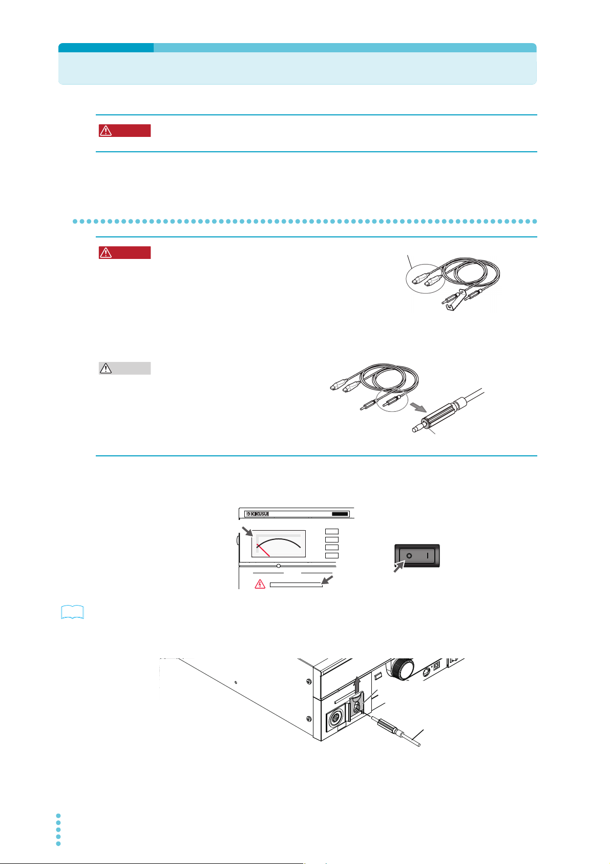
• Parts of the included test leads near the alligator clips
protrude from the vinyl insulation when the wires are
connected. These parts are dangerous. Never come
close to these parts during testing.
• If connections are incomplete, the entire DUT may be
charged to a high voltage. This is dangerous, so be sure to connect the DUT correctly.
• Be sure to connect the LOW test lead (black) first.
Connecting the low and high voltage
terminals incorrectly may lead to
malfunctions. A plate that is designed to
prevent incorrect connections to these
terminals is attached to the LOW test lead
(black). Do not remove this plate.
p.72
Check that the POWER switch is off, that the analog voltmeter is indicating
1
“0,” and that the DANGER LED is off.
AC WITHSTANDING
VOLTAGE TESTER
OS5
T
300
Zero indication
0
OUTPUT
DANGER
Check that there are no tears or breaks in the test lead insulation.
2
Raise the front-panel LOW VOLTAGE terminal’s cable lock, and then connect
3
the LOW test lead (black).
ACW
Off
POWER
Off
26 TOS5300
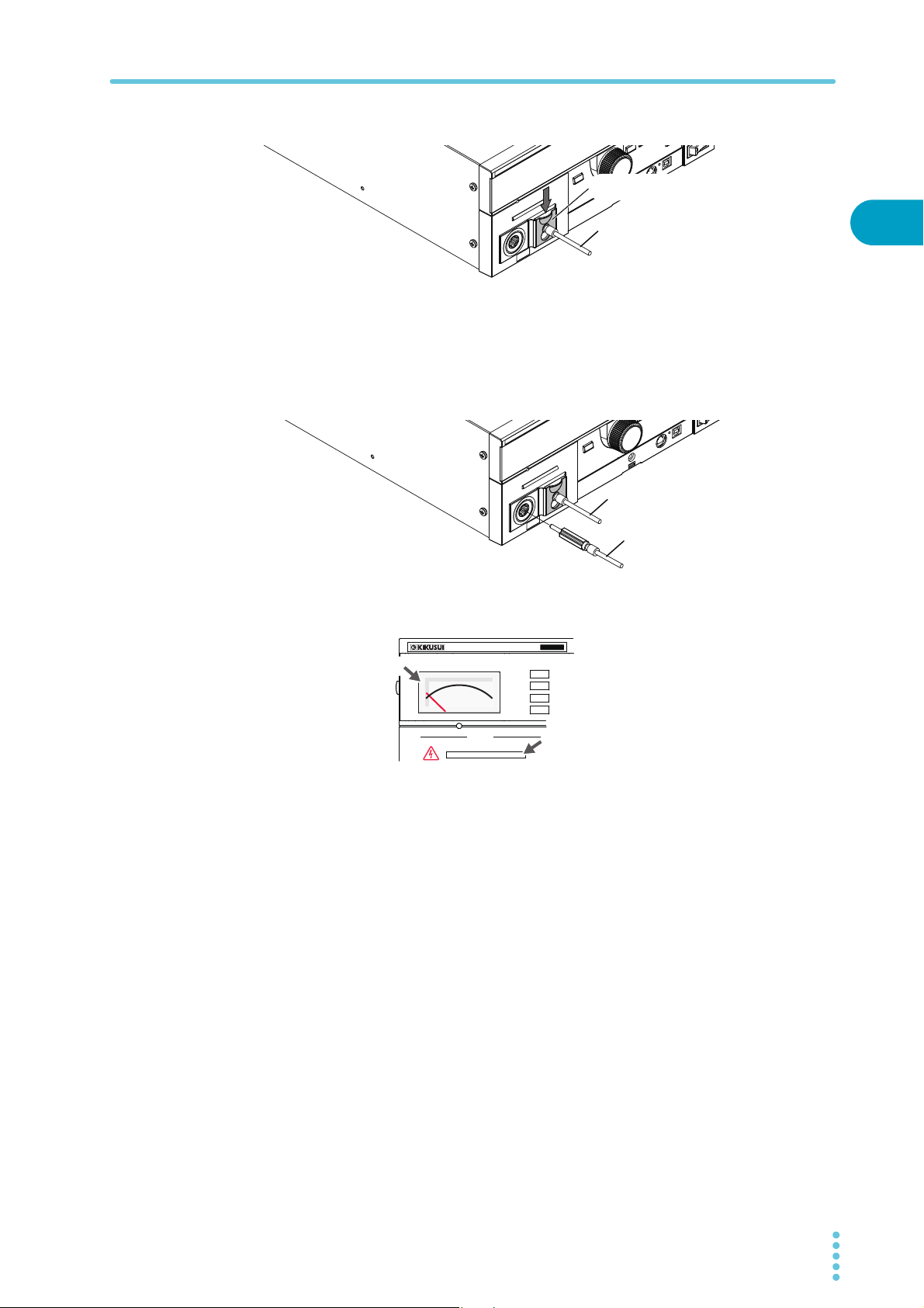
Connecting to the Device under Test (DUT)
LOW test lead (black)
Lower the cable lock.
LOW test lead (black)
HIGH VOLTAGE test lead (red)
OUTPUT
DANGER
T
OS5
300
ACW
AC WITHSTANDING
VOLTAGE TESTER
0
Off
Zero indication
Lower the cable lock to secure the lead in place.
4
Connect the LOW test lead (black) to the DUT.
5
Connect the HIGH VOLTAGE test lead (red) to the DUT.
6
Connect the HIGH VOLTAGE test lead (red) to the front-panel HIGH VOLTAGE
7
terminal.
2
Installation and Preparation
Check that the analog voltmeter is indicating “0” and that the DANGER LED is
8
off.
Reducing the effect of noise
Noise may be generated if the outputs are shorted or if the DUT insulation is damaged. Electronic
devices in the surrounding area may malfunction due to the effect of this noise. To reduce the effect
of noise, connect a toroidal core or a resistor of approximately 470 Ω between the tips of the HIGH
VOLTAGE and LOW test leads and the DUT. Connect the toroidal core or resistor as close to the DUT
as possible.
If you are connecting a toroidal core, it is effective to wrap the test leads two to three times around
a type of core that can be snapped on and that is often used with power cables. This type of core is
usually approximately 20 mm in diameter.
If you are connecting a resistor, pay close attention to the power rating of the resistor. When the
upper limit is 10 mA or less, connect a resistor of approximately 470 Ω (3 W, 30 kV impulse
withstanding voltage). Because this resistor causes the voltage to fall, the voltage that is actually
applied to the DUT is slightly lower than the voltage that is generated from the product’s output
terminals (when a 10 mA current flows, the voltage falls approximately 10 V).
These methods are extremely useful in reducing the effect of noise.
TOS5300 27

Connecting to the Device under Test (DUT)
470 Ω, 3 W
470 Ω, 3 W
DUT
Toroidal core
Toroidal core
HIGH VOLTAGE
terminal
Connect the toroidal core or resistor as close to the DUT
as possible.
LOW terminal
TOS5300 Series
HIGH VOLTAGE
terminal
LOW terminal
TOS5300 Series
DUT
See
Using the optional high voltage test probe (model HP01A-TOS/ HP02A-TOS)
p.17
If you use the optional test probe instead of the test leads, you can use hands-on control to start
tests. For details, see the “OPERATION MANUAL HIGH VOLTAGE TEST PROBE HP01A-TOS/HP02ATOS.”
Disconnecting test leads from the DUT
Check that the analog voltmeter is indicating “0” and that the DANGER LED is
1
off.
Disconnect the HIGH VOLTAGE test lead (red) from the front-panel HIGH
2
VOLTAGE terminal.
Disconnect the HIGH VOLTAGE test lead (red) from the DUT.
3
Disconnect the LOW test lead (black).
4
You can disconnect the LOW test lead (black) first from either the DUT or the
TOS5300 Series.
28 TOS5300

Safety Precautions during Testing
This chapter describes the precautions that
must be followed to perform tests safely.
Pre-Test Inspection
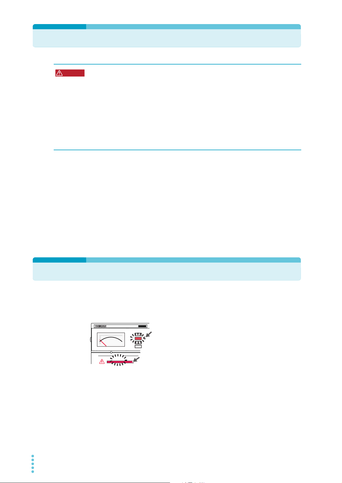
WARNING
OUTPUT
DANGER
T
OS5
300
ACW
AC WITHSTANDING
VOLTAGE TESTER
TEST
On
On
The TEST and DANGER LEDs
light. The TEST LED lights in red.
Possible electric shock.
• During testing, this product supplies a voltage of at least 5 kVAC or 6 kVDC to an external
device. Handling this tester improperly may lead to a fatal accident. To prevent accidents,
strictly follow the precautions and always pay the utmost attention to safety concerns
when you operate the TOS5300 Series.
• This product is a piece of equipment that conforms to IEC Safety Class I (equipment that
has a protective conductor terminal). Be sure to earth ground the product to prevent
electric shock.
• The product is grounded through the power cord ground wire. Connect the protective
conductor terminal to earth ground.
• During testing, be sure to wear rubber gloves for electrical work.
Check the following items before you start testing, and always follow the precautions.
● The power cord is connected to a properly grounded outlet.
● There is no damage such as tears or breaks in the test lead insulation.
● When the POWER switch is turned on, the DANGER LED and the status indicators light.
● During testing, do not touch the items that are charged to a high voltage: the DUT, the
test leads, and the areas near the output terminals.
● During testing, do not turn the POWER switch off except in an emergency.
Testing Precautions
During tests, the TEST and DANGER LEDs light. When these LEDs are lit, the TOS5300 Series is
generating a high voltage. During testing, be sure to wear rubber gloves for electrical work. If
obtaining these gloves is difficult, contact your Kikusui agent or distributor.
30 TOS5300
 Loading...