

Kikusui TOS5050A, TOS5051A Operation Manual
Part No. Z1-002-972, IB004839
Aug. 2009
OPERATION MANUAL
WITHSTANDING VOLTAGE TESTER
TOS5000 Series
TOS5050A
TOS5051A
DANGER
This Tester generates high voltage.
• Any incorrect handling may cause death.
• Read “Handling Precautions” in this manual to
prevent accident.
• Keep this manual near the tester for easy access
of the operator.

Use of Operation Manual
Please read through and understand this Operation Manual before operating the product. After reading,
always keep the manual nearby so that you may refer to it as needed. When moving the product to another
location, be sure to bring the manual as well.
If you find any incorrectly arranged or missing pages in this manual, they will be replaced. If the manual
gets lost or soiled, a new copy can be provided for a fee. In either case, please contact Kikusui distributor/
agent, and provide the “Kikusui Part No.” given on the cover.
This manual has been prepared with the utmost care; however, if you have any questions, or note any
errors or omissions, please contact Kikusui distributor/agent.
Disposing of used Kikusui products in the EU
Under a law adopted by member nations of the European Union (EU), used electric and electronic products carrying the symbol
below must be disposed of separately from general household waste.
This includes the power cords and other accessories bundled with the products. When disposing of a product subject to these regulations, please follow the guidance of your local authority, or inquire with your
Kikusui distributor/agent where you purchased the product.
The symbol applies only to EU member nations.
Disposal outside the EU
When disposing of an electric or electronic product in a country that is not an EU member, please contact
your local authority and ask for the correct method of disposal.
Microsoft, and Visual Basic are registered trademarks of the Microsoft Corporation in the U.S. and other
countries.
Reproduction and reprinting of this operation manual, whole or partially, without our permission is prohibited.
Both unit specifications and manual contents are subject to change without notice.
Copyright© 2003-2009 Kikusui Electronics Corporation

Testing is not possible when
you open the package.
If you turn on the power to the tester simply after taking the tester out
from the box, testing is not possible because the interlock function is
activated.
For a description of the interlock function, see section 6.3.3, “Interlock
Function” in this manual. Then, operate the tester appropriately using the
interlock function.
About this manual
This is the operation manual for the TOS5050A/TOS5051A Withstanding Voltage
tester.
NOTE
■
ROM version of the product to which this manual applies
• TOS5050A: Ver.1.0X
• TOS5051A: Ver.1.0X
To check the version number, refer to 5.2 “Checking the tester Operation.”
When you contact us for any information about the tester, please indicate the version number and the serial number of the tester. The serial number is written on the
rear panel of the tester.
•
To those using the old model TOS5050/5051
The SIGNAL I/O connector on this tester is not compatible with that on the
old model TOS5050/5051 (different pin assignments). Therefore, the 14pin Amphenol plug that is supplied with the tester cannot be shared
between the new and old models.
If you connect the Amphenol plug which you use for the old model to this
tester, testing is not possible because the protection is not released.
To use the Amphenol plug for the old model to this tester, you have to change the
wiring for the interlock function. For details, refer to section 6.3.2 Remote Control through the SIGNAL I/O Connector and 6.3.3 Interlock Function.
TYPE A
The 14-pin Amphenol plug that is supplied with this tester
TOS5051A/5050A I
It is marked “TYPE A” to distinguish
from the plug for the
old model.

To the supervisor in charge of operation
• If the operator does not read the language used in this manual, translate the manual
into the appropriate language.
• Help the operator in understanding this manual before operation.
• Keep this manual near the tester for easy access by the operator.
For your own safety (to avoid electric shock)
While the tester is delivering its test voltage, never touch the following areas, or else,
you will receive electric shock, and run the risk of death.
• the output terminal
• the test leads connected to the output terminal
• the Device Under Test (DUT)
• any area electrically connected to the output terminal.
• any area electrically connected to the output terminal immediately after the output
has been cut off in the DC test mode.
Also, electric shock or accident may occur in the following cases:
• the tester being operated without grounding.
• if the gloves for electrical work are not used.
• approach any part connected to the output terminal while the power of the tester is
turned on.
• approach any part connected to the output terminal immediately after the power of
tester has been turned off in the DC test mode.
II TOS5051A/5050A
Power Requirements of this Product
Power requirements of this product have been changed and the relevant sections of the Operation
Manual should be revised accordingly.
(Revision should be applied to items indicated by a check mark .)
✓
Input voltage
The input voltage of this product is VAC ,
and the voltage range is
to VAC. Use the product within this range only.
Input fuse
The rating of this product's input fuse is A, VAC, and .
WARNING
• To avoid electrical shock, always disconnect the power cord or turn off the
switch on the switchboard before attempting to check or replace the fuse.
• Use a fuse element having a shape, rating, and characteristics suitable
for this product. The use of a fuse with a different rating or one that short
circuits the fuse holder may result in fire, electric shock, or irreparable
damage.
TOS5051A/5050A III
WARNING
Safety Symbols
For the safe use and safe maintenance of this product, the following
symbols are used throughout this manual and on the product. Understand the meanings of the symbols and observe the instructions they
indicate (the choice of symbols used depends on the products).
Indicates that a high voltage (over 1000 V) is used here. Touch-
OR
ing the part causes a possibly fatal electric shock. If physical
contact is required by your work, start work only after you make
sure that no voltage is output here.
DANGER
CAUTION
Indicates an imminently hazardous situation which, if ignored,
will result in death or serious injury.
Indicates a potentially hazardous situation which, if ignored,
could result in death or serious injury.
Indicates a potentially hazardous situation which, if ignored, may
result in damage to the product and other property.
Shows that the act indicated is prohibited.
Is placed before the sign “DANGER,” “WARNING,” or “CAUTION” to emphasize these. When this symbol is marked on the
product, see the relevant sections in this manual.
Indicates a protective conductor terminal.
Indicates a chassis (frame) terminal.
IV Safety Symbols TOS5051A/5050A
Safety Precautions
Operation
Manual
Line
Voltage
The following safety precautions must be observed to avoid fire hazard, electrical shock, accidents, and other failures. Keep them in
mind and make sure that all of them are observed properly.
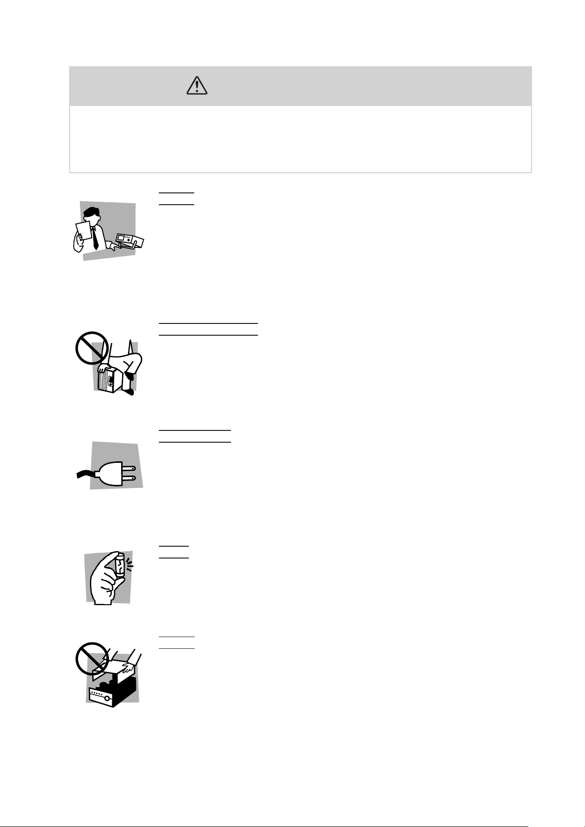
User
s
• This product must be used only by qualified personnel who understand the contents of this operation manual.
• If it is handled by disqualified personnel, personal injury may result. Be sure to handle it under supervision of qualified personnel (those who have electrical knowledge.)
• This product is not designed or manufactured for general home or consumer use.
Purposes of use
• Do not use the product for purposes other than those described in the operation
manual.
Input po
• Use the product with the specified input power voltage.
• For applying power, use the power cord provided. Note that the provided power
cord is not use with some products that can switch among different input power
voltages or use 100 V and 200 V without switching between them. In such a case,
use an appropriate power cord.
wer
Fuse
• With products with a fuse holder on the exterior surface, the fuse can be replaced
with a new one. When replacing a fuse, use the one which has appropriate shape,
ratings, and specifications.
Cover
• There are parts inside the product which may cause physical hazards. Do not
remove the external cover.
TOS5051A/5050A Safety Precautions V
Installation
Check?
• When installing products be sure to observe “2.2 Precautions Concerning Installation Location” described in this manual.
• To avoid electrical shock, connect the protective ground terminal to electrical
ground (safety ground).
• When connecting the power cord to a switchboard, be sure work is performed by
a qualified and licensed electrician or is conducted under the direction of such a
person.
• When installing products with casters, be sure to lock the casters.
Relocation
• Turn off the power switch and then disconnect all cables when relocating the
product.
• Use two or more persons when relocating the product which weights more than
20 kg. The weight of the products can be found on the rear panel of the product
and/or in this operation manual.
• Use extra precautions such as using more people when relocating into or out of
present locations including inclines or steps. Also handle carefully when relocating tall products as they can fall over easily.
• Be sure the operation manual be included when the product is relocated.
Operation
• Check that the AC input voltage setting and the fuse rating are satisfied and that
there is no abnormality on the surface of the power cord. Be sure to unplug the
power cord or stop applying power before checking.
• If any abnormality or failure is detected in the products, stop using it immediately.
Unplug the power cord or disconnect the power cord from the switchboard. Be
careful not to allow the product to be used before it is completely repaired.
• For output wiring or load cables, use connection cables with larger current capacity.
• Do not disassemble or modify the product. If it must be modified, contact Kikusui
distributor/agent.
Maintenance and c
• To avoid electrical shock, be absolutely sure to unplug the power cord or stop
applying power before performing maintenance or checking.
• Do not remove the cover when performing maintenance or checking.
• To maintain performance and safe operation of the product, it is recommended
that periodic maintenance, checking, cleaning, and calibration be performed.
vice
Ser
hecking
• Internal service is to be done by Kikusui service engineers. If the product must be
adjusted or repaired, contact Kikusui distributor/agent.
VI Safety Precautions TOS5051A/5050A
Fr
ont Panel and Rear Panel
• When accessing the panels, be sure to read chapter 3, “Handling Precautions.”
Deflected meter pointer means
hat the tester is in the
“DANGER! HIGH VOLTAGE”
state.
Be sure to read the manual before
controlling the tester remotely.
See section 2.6, “Remote Control.”
Lighted lamp means that the
tester is in the
“DANGER! HIGH VOLTAGE”
state.
Be sure to stop the tester
before changing test
parameters.
Start connecting from
the low voltage test
HIGH VOLTAGE Output Terminal
DANGER!
lead.
Be sure to read the manual before
controlling the tester remotely.*
See section 2.6, “Remote Control.”
RS232C
SIGNAL I O
AC LINE 50 60Hz
800VA MAX
:
7
:
6
:
5
:
4
:
3
:
2
:
1
:
8
:
9
:
10
:
11
:
12
:
13
:
14
READY
L FAIL
U FAIL
PASS
TEST
H.V ON
INTERLOCK
PROTECTION
INTERLOC K
RR START
RR STOP
RR ENABLE
ISOL COM
ISOL COM
+
-
IF THIS CO LUMN IS BLA NK,
THE UNI T IS WIRED I N 100V
SETT ING
LINE VO LTAGE
SUPPLY
STANDARD
100 V
110V
120V
220V
230V
240V
WARNING
TO AVOID ELECTRIC SHOCK, THE POWER CORD PROTECTIVE GROUNDING
CONDUCTOR OR THE PROTECTIVE CONDUCTOR TERMINAL MUST BE
CONNECTED TO GROUND.
DO NOT REMOVE COVERS, REFER SERVICING TO QUALIFIED PERSONNEL.
USE ONLY
BUZZER AND
WARNING LIGH T
.3A MA X
AC100V 0
STATUS OUT
TEST MODE
OFF ON
OFF ON
DOUBLE ACTI ON
PASS HOLD
MOMENTARY
FAIL M ODE
H.V ON
TEST
PASS
U FAIL
L FAIL
READY
PROTECTION
POWER ON
For your safety, be sure to connect to the earth ground.
See section 2.6, “Grounding (Earth).”
Before turning ON the
POWER switch, be certain
that the TEST VOLTAGE
control is in the “0” position.
No
.
KIKUSUI ELECTRONICS CORP.
MADE IN JAPAN
* The SIGNAL I/O connector on this tester is not compatible with that on the old model TOS5050/5051
(different pin assignments). For details, refer to section 6.3.2 Remote Control through the SIGNAL I/O
Connector and 6.3.3 Interlock Function.
TOS5051A/5050A Safety Precautions VII

Contents
Power Requirements of this Product ___________________________ III
Safety Symbols ___________________________________________ IV
Safety Precautions _________________________________________ V
Chapter 1 General ________________________________________ 1-1
Chapter 2 Installation and Preparation_________________________ 2-1
1.1 Overview - - - - - - - - - - - - - - - - - - - - - - - - - - - - - - - - - - - - - - - - - - - - 1-2
1.2 Features - - - - - - - - - - - - - - - - - - - - - - - - - - - - - - - - - - - - - - - - - - - - - 1-2
1.3 Options - - - - - - - - - - - - - - - - - - - - - - - - - - - - - - - - - - - - - - - - - - - - - 1-5
2.1 Checking the Package Contents - - - - - - - - - - - - - - - - - - - - - - - - - - - - - 2-2
2.2 Precautions Concerning Installation Location - - - - - - - - - - - - - - - - - - - - 2-3
2.3 Precautions When Moving the tester - - - - - - - - - - - - - - - - - - - - - - - - - - 2-4
2.4 AC Line Requirements - - - - - - - - - - - - - - - - - - - - - - - - - - - - - - - - - - - 2-4
2.5 Connecting the Power Cord - - - - - - - - - - - - - - - - - - - - - - - - - - - - - - - - 2-5
2.6 Grounding (Earth) - - - - - - - - - - - - - - - - - - - - - - - - - - - - - - - - - - - - - - 2-6
Chapter 3 Handling Precautions _____________________________ 3-1
3.1 Preparative Procedures - - - - - - - - - - - - - - - - - - - - - - - - - - - - - - - - - - - 3-2
3.1.1 Wearing Insulation Gloves - - - - - - - - - - - - - - - - - - - - - - - - - - 3-2
3.1.2 Grounding the Tester - - - - - - - - - - - - - - - - - - - - - - - - - - - - - - 3-2
3.2 Warnings and Cautions When Operating the Tester - - - - - - - - - - - - - - - - 3-2
3.2.1 Before Turning ON the AC Input Power - - - - - - - - - - - - - - - - - 3-2
3.2.2 Connecting the Low Test Lead - - - - - - - - - - - - - - - - - - - - - - - - 3-2
3.2.3 Connecting the High Test Lead - - - - - - - - - - - - - - - - - - - - - - - 3-3
3.2.4 Before Changing Test Parameters - - - - - - - - - - - - - - - - - - - - - - 3-3
3.2.5 Precautions for Pausing Tests - - - - - - - - - - - - - - - - - - - - - - - - - 3-4
3.2.6 Items Charged Up to Dangerous High Voltages - - - - - - - - - - - - 3-4
3.3 Warnings after Turning OFF the Power - - - - - - - - - - - - - - - - - - - - - - - - 3-5
3.3.1 Check Items after Turning OFF the Power - - - - - - - - - - - - - - - - 3-5
3.3.2 Residual High Voltages (TOS5051A Only) - - - - - - - - - - - - - - - 3-5
3.4 Warnings for Remote Control - - - - - - - - - - - - - - - - - - - - - - - - - - - - - - 3-6
3.5 Inhibitions - - - - - - - - - - - - - - - - - - - - - - - - - - - - - - - - - - - - - - - - - - - 3-6
3.5.1 Inhibition of Rapid ON/OFF Repetitions - - - - - - - - - - - - - - - - - 3-6
3.5.2 Inhibition of Shorting to Earth Ground - - - - - - - - - - - - - - - - - - 3-6
3.6 Actions to Be Taken in Emergency - - - - - - - - - - - - - - - - - - - - - - - - - - - 3-7
3.7 Breakdown - - - - - - - - - - - - - - - - - - - - - - - - - - - - - - - - - - - - - - - - - - - 3-7
3.7.1 Stopping the Use of Broken Testers - - - - - - - - - - - - - - - - - - - - 3-7
3.7.2 DANGER Lamp - - - - - - - - - - - - - - - - - - - - - - - - - - - - - - - - - 3-7
3.8 Wattage, Heat, and Other Limiting Conditions of Use - - - - - - - - - - - - - - 3-8
Chapter 4 Description of Front and Rear Panel Items _____________ 4-1
4.1 Description of Front Panel Items - - - - - - - - - - - - - - - - - - - - - - - - - - - - 4-2
VIII Contents TOS5051A/5050A

4.2 Display Items - - - - - - - - - - - - - - - - - - - - - - - - - - - - - - - - - - - - - - - - 4-13
4.3 Description of Rear Panel Items - - - - - - - - - - - - - - - - - - - - - - - - - - - 4-19
Chapter 5 Preparative Test Procedures _______________________ 5-1
5.1 Initial Setup - - - - - - - - - - - - - - - - - - - - - - - - - - - - - - - - - - - - - - - - - - 5-2
5.2 Checking the Tester Operation - - - - - - - - - - - - - - - - - - - - - - - - - - - - - 5-4
5.3 Checking the Tester before Starting Test Operation - - - - - - - - - - - - - - - 5-6
Chapter 6 Test Procedures _________________________________ 6-1
6.1 AC Withstanding Voltage Test Procedure - - - - - - - - - - - - - - - - - - - - - - 6-2
6.1.1 Selecting an AC Test Voltage Range - - - - - - - - - - - - - - - - - - - - 6-2
6.1.2 Setting the Upper Cutoff Current - - - - - - - - - - - - - - - - - - - - - - - 6-2
6.1.3 Setting the Lower Cutoff Current - - - - - - - - - - - - - - - - - - - - - - - 6-3
6.1.4 Setting the Test Time - - - - - - - - - - - - - - - - - - - - - - - - - - - - - - 6-5
6.1.5 Setting the Test Voltage - - - - - - - - - - - - - - - - - - - - - - - - - - - - - 6-6
6.1.6 Connecting the DUT - - - - - - - - - - - - - - - - - - - - - - - - - - - - - - - 6-6
6.1.7 Executing a Test - - - - - - - - - - - - - - - - - - - - - - - - - - - - - - - - - - 6-7
6.2 DC Withstanding Voltage Test Procedure (TOS5051A Only) - - - - - - - 6-11
6.2.1 Selecting a DC Test Voltage Range - - - - - - - - - - - - - - - - - - - - 6-11
6.2.2 Setting the Upper Cutoff Current - - - - - - - - - - - - - - - - - - - - - - 6-12
6.2.3 Setting the Lower Cutoff Current - - - - - - - - - - - - - - - - - - - - - 6-13
6.2.4 Setting the Test Time - - - - - - - - - - - - - - - - - - - - - - - - - - - - - 6-14
6.2.5 Setting the Test Voltage - - - - - - - - - - - - - - - - - - - - - - - - - - - - 6-15
6.2.6 Connecting the DUT - - - - - - - - - - - - - - - - - - - - - - - - - - - - - - 6-15
6.2.7 Executing a Test - - - - - - - - - - - - - - - - - - - - - - - - - - - - - - - - - 6-16
Chap.1Chap.2Chap.3Chap.4Chap.5Chap.6Chap.7Chap.8Chap.9Chap.10
6.3 Remote Control - - - - - - - - - - - - - - - - - - - - - - - - - - - - - - - - - - - - - - - 6-20
6.3.1 Remote Control through the REMOTE Connector - - - - - - - - - - 6-20
6.3.2 Remote Control through the SIGNAL I/O Connector - - - - - - - - 6-21
6.3.3 Interlock Function - - - - - - - - - - - - - - - - - - - - - - - - - - - - - - - 6-24
6.3.4 Start/Stop Control - - - - - - - - - - - - - - - - - - - - - - - - - - - - - - - - 6-25
6.3.5 Output Signal - - - - - - - - - - - - - - - - - - - - - - - - - - - - - - - - - - - 6-27
6.4 STATUS OUT - - - - - - - - - - - - - - - - - - - - - - - - - - - - - - - - - - - - - - - 6-28
6.5 Settings for Special Test Modes - - - - - - - - - - - - - - - - - - - - - - - - - - - - 6-29
6.5.1 DOUBLE ACTION Switch - - - - - - - - - - - - - - - - - - - - - - - - - - 6-29
6.5.2 PASS HOLD Switch - - - - - - - - - - - - - - - - - - - - - - - - - - - - - - 6-29
6.5.3 MOMENTARY Switch - - - - - - - - - - - - - - - - - - - - - - - - - - - - 6-30
6.5.4 FAIL MODE Switch - - - - - - - - - - - - - - - - - - - - - - - - - - - - - - 6-30
Chapter 7 RS-232C Interface _______________________________ 7-1
7.1 Connecting the Cable - - - - - - - - - - - - - - - - - - - - - - - - - - - - - - - - - - - - 7-2
7.2 RS-232C Specifications - - - - - - - - - - - - - - - - - - - - - - - - - - - - - - - - - - 7-2
7.3 Communication Method - - - - - - - - - - - - - - - - - - - - - - - - - - - - - - - - - - 7-3
7.4 Talk Mode - - - - - - - - - - - - - - - - - - - - - - - - - - - - - - - - - - - - - - - - - - - 7-3
7.5 Before Using the RS-232C - - - - - - - - - - - - - - - - - - - - - - - - - - - - - - - - 7-5
TOS5051A/5050A Contents IX

7.6 RS-232C Commands and Responses - - - - - - - - - - - - - - - - - - - - - - - - - - 7-7
7.7 Sample Program - - - - - - - - - - - - - - - - - - - - - - - - - - - - - - - - - - - - - - 7-10
Chapter 8 Operating Principle _______________________________ 8-1
8.1 Block Diagrams - - - - - - - - - - - - - - - - - - - - - - - - - - - - - - - - - - - - - - - - 8-2
8.2 Zero-turn-on Switch - - - - - - - - - - - - - - - - - - - - - - - - - - - - - - - - - - - - - 8-4
8.3 Delay Time for Pass/Fail Judgment in DC Mode - - - - - - - - - - - - - - - - - 8-5
8.4 Automatic Discharge Function - - - - - - - - - - - - - - - - - - - - - - - - - - - - - - 8-5
Chapter 9 Maintenance ____________________________________ 9-1
9.1 Cleaning - - - - - - - - - - - - - - - - - - - - - - - - - - - - - - - - - - - - - - - - - - - - - 9-2
9.2 Checking the Cord and Leads - - - - - - - - - - - - - - - - - - - - - - - - - - - - - - 9-2
9.3 Maintenance - - - - - - - - - - - - - - - - - - - - - - - - - - - - - - - - - - - - - - - - - - 9-3
9.4 Calibration - - - - - - - - - - - - - - - - - - - - - - - - - - - - - - - - - - - - - - - - - - - 9-3
Chapter 10 Specifications _________________________________ 10-1
10.1 Basic Performance - - - - - - - - - - - - - - - - - - - - - - - - - - - - - - - - - - - - - 10-2
10.2 Interface and Other Functions - - - - - - - - - - - - - - - - - - - - - - - - - - - - - 10-5
10.3 General Specifications - - - - - - - - - - - - - - - - - - - - - - - - - - - - - - - - - - 10-7
10.4 Outline Drawing - - - - - - - - - - - - - - - - - - - - - - - - - - - - - - - - - - - - - - 10-8
Index ___________________________________________________ I- 1
X Contents TOS5051A/5050A

Chapter 1 General
1
1
Chap.1
General
This chapter gives an overview and introduces the features of the tester.
TOS5051A/5050A 1-1

1.1 Overview
The TOS5051A/5050A is a tester for carrying out withstanding voltage tests on electronic devices and electronic parts. The TOS5051A is capable of carrying out both
AC tests and DC tests; the TOS5050A is capable of carrying out AC tests.
This tester integrates new ideas and technologies with the conventional, consistent
philosophy of providing the highest safety, reliability, and operability to the operator.
WARNING
• The tester is equipped with various safety features to protect the operator
from hazards. However, when the tester is in use, high voltage is applied
to the DUT. Inadvertently touching the DUT, test leads, probes, and output
terminals can cause electric shock.
• Be sure to provide full protective measures around the tester and DUT to
prevent electric shock--such as to enclose the test area with rope fences
to prevent access.
1.2 Features
1. Tests complying with major industrial standards
The tester can carry out withstanding (dielectric strength) tests on electronic
devices and electronic parts in compliance with JIS, UL, CSA, BS, and other
major electrical standards and ordinances.
2. Transformer capacity of 500 VA
The tester is equipped with a transformer, rated 500 VA.
3. Rational layouts of keys and switches
The keys have a slant-plane for easy viewing and convenient operation. The switch
for AC/DC select and test voltage range select and the control for test voltage
adjustment are installed concentrically, allowing you to operate them conveniently
with two concentric knobs. For the adjustment of the pass/fail-judgment limit current and timer, dedicated increment/decrement keys are provided. These keys and
switches, together with the large display easy to view, are laid out rationally and
will assist you to conduct your tests accurately and efficiently.
4. A large color display
The tester has a large color vacuum fluorescent display. The wide viewing angle
and high intensity indicates information in clearly. Various information including
test conditions, instrument status, measured values, and result of pass/fail judgment are indicated using large letters and color assisting you to conduct your tests
accurately and efficiently.
1-2 TOS5051A/5050A

5. An analog voltmeter and a digital voltmeter
The tester is equipped with an analog voltmeter (±5 % FS) and a digital voltmeter (±1.5 % FS)--the former for quick grasp of the voltage and the latter for
more accurate readout--assisting you to conduct your tests rapidly but accurately.
6. A digital ammeter
The digital ammeter can be used to measure the current that flows through the
DUT (device under test).
7. A window comparator for pass/fail judgment
The tester has a window comparator for pass/fail judgment with reference to
both upper (U) and lower (L) criteria (cutoff current). The comparator generates a FAIL signal when the measured current that flows through the DUT is
greater than the preset upper limit criterion or when it is less than the preset
lower limit criterion. The L FAIL detection function contributes to improve the
test reliability by detecting open-circuits and bad contacts of the test leads. The
tester has a separate indicator and signal output for each type of failure (U type
and L type). This allows you to immediately find out whether the failure is a
withstand voltage failure or an open-circuit/bad-contact failure.
You can preset the upper limit and lower limit currents (cutoff currents) independently, within the ranges shown in the following table.
Chap.1
General
Model Preset range of upper and lower limits
TOS5051A 0.1 mA to 110 mAAC 200 steps
0.1 mA to 11 mADC 101 steps
TOS5050A 0.1 mA to 110 mAAC 200 steps
8. A digital timer
The timer allows you to preset the period during which the test voltage is to be
applied to the DUT. The preset range is 0.5 to 999 seconds (in 1895 steps).
When the timer function is ON, the preset period is decreased and the timer
indicates the remaining period; when it is OFF, time is increased and the timer
indicates the elapsed period.
9. Remote control function
The tester has functions for remote start/stop control operation. That is, it has a
5-pin DIN connector (for the optional remote control box or high voltage test
probe) on its front panel and a 14-pin Amphenol connector on its rear panel.
The remote control function, together with the status signal function, will help
you conduct efficient automatic labor-saving tests.
TOS5051A/5050A 1-3
10.Status signals
The tester delivers seven status signals--namely, H.V ON, TEST, PASS, U
FAIL, L FAIL, READY, and PROTECTION--through its 14-pin Amphenol
connector (shared with the remote control signals) on the rear panel. The signal form is open collector. The tester can deliver a 100 VAC output in response
to one of eight states--namely, H.V ON, TEST, PASS, U FAIL, L FAIL,
READY, PROTECTION, and POWER ON. Used in conjunction with the
remote control function, these status signals will help you to conduct still more
efficient automatic labor-saving tests.
11.Compact and light
The tester is compact and light as shown below.
Model Overall dimensions Weight
TOS5051A
320 mm (W) × 132 mm (H) × 300 mm (D)
TOS5050A 15 kg
16 kg
12.Memory backup function
When you turn the tester OFF, the tester stores its existing test state in its nonvolatile memory. When you turn the tester ON the next time, the tester recalls
the stored information and restores the test state that existed when you turned
OFF the power last time.
13.A safer high voltage output terminal
The lead insertion portion of the high voltage output terminal is structured with
a restriction for safer connection.
14.A DANGER lamp
The tester has a large and bright DANGER lamp. This lamp lights when electric charge is remaining on the output terminal, warning you of a possible electric shock hazard.
15.Interlock function
The tester has an interlock function that shuts down the output voltage in synchronization with the external device. When this function is activated, the output is shut down and keeps tests from being executed.
The interlock function operates even if there is open-circuit or bad contact in
the signal line, thereby enhancing further the operation safety.
16.Keylock function
The tester has a keylock function to disable all keys (except the START/STOP
keys) to guard against inadvertent key operation by the operator or an unauthorized person. This improves the reliability of tests.
17.Switches for safer operation
A rotary switch is used for AC/DC test mode selection and test voltage range
selection. The START switch is of a recessed type. These features, together
with the keylock function, enhance operation reliability and safety.
1-4 TOS5051A/5050A
18.Noise-resistant circuits
The internal circuits of the tester are designed to be highly resistant against
noise, thereby enhancing the operation reliability.
19.Automatic discharge function (TOS5051A only)
When the DC test output voltage is turned off, the output circuit is automatically discharged, thereby discharging the charge in the device under test
(DUT). This feature, together with the DANGER lamp, enhances the test operation safety.
20.A DC/DC converter for quality DC test voltage (TOS5051A only)
The tester has a DC/DC converter which generates a quality test voltage of
high stability with less ripple.
21.Equipped with a RS-232C interface for outputting test data
and test results
The measurement results can be output to a PC or printer.
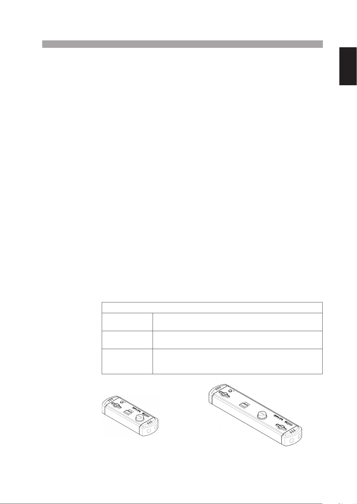
1.3 Options
Model RC01-TOS/RC02-TOS remote control box
Chap.1
General
Model RC01-TOS or RC02-TOS remote control box is used to remotely control the
start/stop of test operation of the tester. Connect the Control Box to the REMOTE
connector on the front panel of the tester. The RC01-TOS has one START switch;
RC02-TOS has two START switches. The test starts when you press both switches
at the same time, thereby enhancing the operating safety.
Description of the RC01-TOS/RC02-TOS function
OPERATE switch
START switch
STOP switch
This switch enables (when ON) or disables (when OFF) the START
switch or switches.
The test starts when you press this switch (or switches) if the
OPERATE switch is ON and the tester is in the READY status.
This switch terminates the test (cuts off the test voltage or resets the
tester from the FAIL or other particular status--its functions are the
same with those of the STOP switch on the front panel of the tester.
RC01-TOS RC02-TOS
200(W) × 70(Η) × 39(D) mm 330(W) × 70(Η) × 39(D) mm
TOS5051A/5050A 1-5
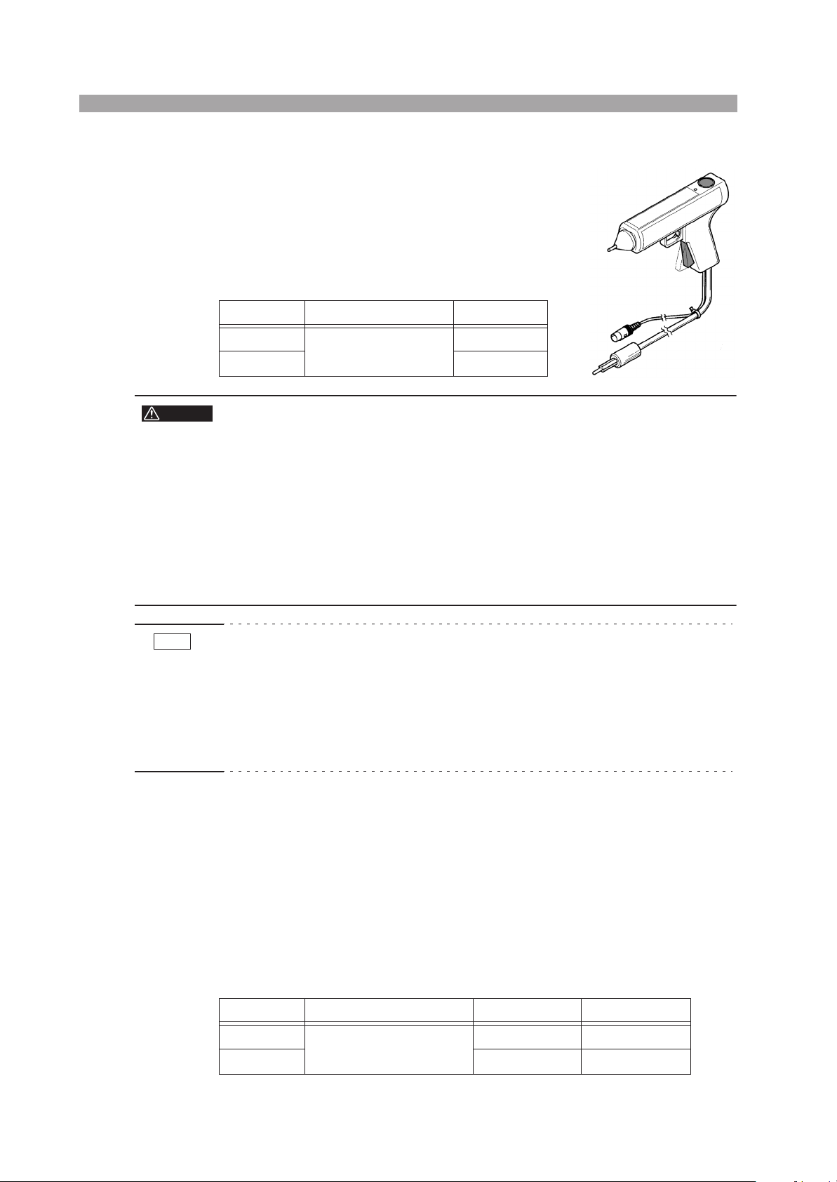
Model HP01A-TOS/HP02A-TOS high voltage test probe
HA01-TOS
The high voltage test probe renders a three-fold operating safety. The test voltage is not delivered unless
you squeeze with one hand the slide lever of the grip
of the probe and pull the trigger while you press with
the other hand the switch on top of the probe. If you
release your hand, the probe immediately delivers a
STOP signal to cut off the test voltage.
Model Voltage rating Cable length
WARNING
NOTE
HP01A-TOS
HP02A-TOS Approx. 3.5 m
4 kVAC (rms), 50/60 Hz
5 kVDC
Approx. 1.8 m
• The maximum voltage rating of the probe is 4
kVACrms or 5 kVDC. Never apply voltages
exceeding the voltage rating.
• Do not connect the probe to or disconnect it from the DUT while the test
voltage is being delivered. If you do, the DUT may be damaged. If you disconnect the probe from the DUT while the test voltage is being delivered,
the DUT will remain charged at the high test voltage. Before connecting
the probe to the DUT, be sure that the test voltage is OFF (the LED on top
of the probe is OFF); before disconnecting the probe from the DUT, be
sure that the test voltage is OFF (the LED is OFF).
• If you need to perform a test in compliance to the UL Standard by using the probe,
turn the FAIL MODE switch (DIP switch on the rear panel) of the tester to ON. If
this switch is ON, the tester behaves in the following manner and you can accurately confirm the FAIL status. When a test is terminated due to a failure, the FAIL
status on the tester is not reset even when you release the probe. To reset the FAIL
status, you must press the STOP switch on the tester. For details, refer to Section
6.5.4, “FAIL MODE Switch” (page 6-30).
Model PL01-TOS warning light unit
This unit indicates that the tester is in the TEST-ON status (delivering the test voltage).
Model BZ01-TOS buzzer unit
This unit may be used when the sound generated by the buzzer housed in the tester
is insufficient. This unit can be driven by the FAIL status signal of the tester.
High Voltage test leads
Model Voltage rating Cable length Remarks
TL01-TOS
TL02-TOS Approx. 3.0 m
1-6 TOS5051A/5050A
5 kVAC (rms), 50/60 Hz
5 kVDC
Approx. 1.5 m Tester accessory

2
2
Chapter 2 Installation and
Preparation
This chapter describes the procedures from unpacking to preparation before use.
Chap.2
Installation and Preparation
TOS5051A/5050A 2-1
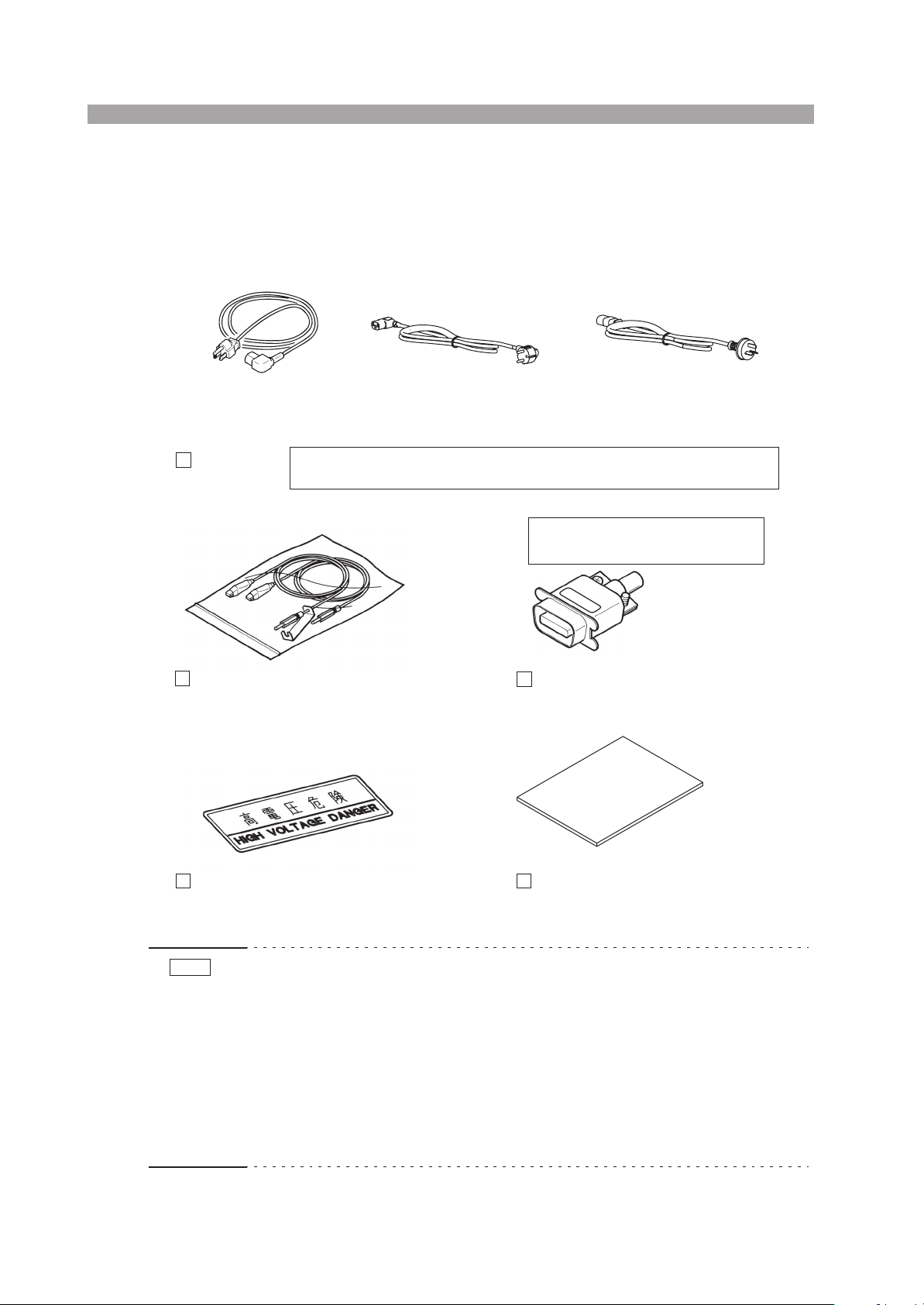
2.1 Checking the Package Contents
When you receive the product, check that all accessories are included and that the
product and accessories have not been damaged during transportation.
If any of the accessories are damaged or missing, contact Kikusui distributor/agent.
or or
Rated voltage: 125 Vac
PLUG: NEMA5-15
[85-AA-0003] [85-AA-0005]
Power cord 1
(1 piece)
High voltage test leads
TL01-TOS (1.5 meters) (1 set)
The power cord that is provided varies depending on the destination for the product
at the factory-shipment.
[82970]
Rated voltage: 250 Vac
PLUG: CEE7/7
[85-AA-0005]
Rated voltage: 250 Vac
PLUG: GB1002
[85-10-0790]
The plug that is supplied cannot be
shared between the new and old models.
TYPE
A
[83-21-4000]
14-pin Amphenol connector plug* (1 piece)
Assembly type
[A8-210-202]
“HIGH VOLTAGE DANGER” sticker (1 sheet)
Operation manual (1 copy)
[Z1-002-972]
Fig.2-1 Accessories
NOTE
• It is recommended that all packing materials be saved, in case the product needs
to be transported at a later date.
• Attach the “HIGH VOLTAGE DANGER” sticker to a conspicuous place on the
tester or near the installation location.
•*
To those using the old model TOS5050/5051
The SIGNAL I/O connector on this tester is not compatible with that on the old model
TOS5050/5051 (different pin assignments). Therefore, the 14-pin Amphenol plug that
is supplied with the tester cannot be shared between the new and old models.
It is marked “TYPE A” to distinguish the two.
2-2 TOS5051A/5050A

2.2 Precautions Concerning Installation Location
This section describes the precautions to be taken when installing the product. Make
sure to observe them.
■
Do not use the tester in a flammable atmosphere.
To prevent the possibility of explosion or fire, do not use the product near alcohol,
thinner or other combustible materials, or in an atmosphere containing such vapors.
■
Avoid locations where the tester is exposed to high temperature or direct sunlight.
Do not place the product near a heater or in areas subject to drastic temperature changes.
Operating temperature range: 0 °C to +40 °C (+32 °F to +104 °F)
Storage temperature range: -20
■
Avoid humid environments.
Do not place the product in high-humidity locations--near a boiler, humidifier, or
water supply.
Operating humidity range: 20 % to 80 % RH (no condensation)
Storage humidity range: 0 to 80 % RH (no condensation)
Condensation may occur even within the operating humidity range. In such case, do
not use the product until the condensation dries up completely.
°
C to +70 °C (-4 °F to +158 °F)
Chap.2
Installation and Preparation
■
Do not place the tester in a corrosive atmosphere.
Do not install the tester in a corrosive atmosphere or in environments containing sulfuric
acid mist, etc. This may cause corrosion of various conductors and bad contacts of connectors inside the tester leading to malfunction and failure, or in the worst case, a fire.
■
Do not place the tester in a dusty location.
Accumulation of dust can lead to electric shock or fire.
■
Do not use the tester where ventilation is poor.
Secure adequate space around the product so that air can circulate around it.
■
Do not place objects on top of the tester.
Placing objects on top of the tester can cause failures (especially heavy objects).
■
Do not place the tester on an inclined surface or location subject to vibrations.
The tester may fall or tip over causing damages and injuries.
■
Do not use the tester in a location where strong magnetic or electric fields are nearby or a location where large amount of distortion and noise is present on the input power supply waveform.
The product may malfunction.
TOS5051A/5050A 2-3

■
Do not use the tester near highly sensitive measuring instruments or transceivers.
Do not operate the tester near highly sensitive measuring instruments such as communication receivers, because the noise generated by the tester may interfere with
such devices.
Above 3 kV test voltage, the tester may produce corona discharge between its test
lead clips which will generate a significant amount of broadband RF emission. To
minimize this effect, separate the alligator clips and leads away from each other and
from conducting surfaces, especially sharp metal edges.
■ Secure adequate space around the power plug.
Do not insert the power plug to an outlet where accessibility to the plug is poor.
And, do not place objects near the outlet that would result in poor accessibility to
the plug.
2.3 Precautions When Moving the tester
When moving the tester to the installation location or when transporting the tester,
note the following points.
■ Turn OFF the POWER switch.
Moving the tester with the power ON may result in electric shock or damage.
■ Remove all wiring.
Moving the tester with the cables connected can cause wires to break or injuries due
to the tester falling over.
■ When transporting the tester, be sure to use the original packing materials.
Otherwise, damage may result from vibrations or from the tester falling during
transportation.
2.4 AC Line Requirements
The AC line requirements of the tester are as follows:
Nominal voltage Voltage tolerance Nominal frequency
100 V ±10 % of nominal voltage 50/60 Hz
The standard nominal AC line voltage of the tester is 100 V. The tester normally
operates on an AC line voltage within ±10 % of the nominal voltage. If the line voltage is outside of this range, the tester may not operate normally or may be damaged.
If your AC line voltage is outside of this range, be sure to convert it into within this
range by using an autotransformer or other appropriate means.
2-4 TOS5051A/5050A
Testers that operate on other AC line voltages as shown below also are available as
factory-modification options.
Optional AC line voltages 110 V 120 V 220 V 230 V 240 V
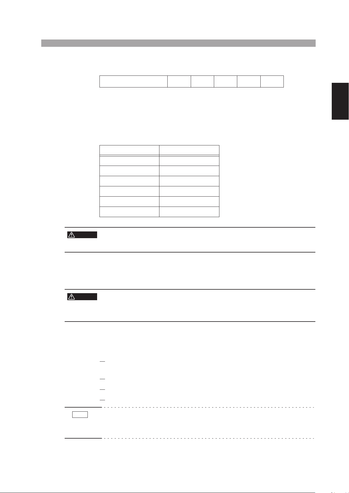
The following table is printed on the rear panel of the tester. If nothing is marked in
the “SETTING SUPPLY” column, the nominal voltage is 100 V. The change in the
nominal voltage is made at the factory. If a change has been made, a mark is indicated to the left of the corresponding voltage.
Before turning ON the AC input power of the tester, be sure that your AC line voltage conforms with the nominal voltage indicated on the indicator sheet.
SETTING SUPPLY LINE VOLTAGE
STANDARD 100 V
110 V
120 V
Chap.2
220 V
230 V
240 V
WARNING
• Do not modify your tester by yourself. Consult Kikusui distributor/agent to
have your tester modified.
2.5 Connecting the Power Cord
WARNING
• This product is designed to be connected to a power supply classified as
overvoltage category II. Do not connect to a power supply classified as
overvoltage category III or IV.
• Do not use the power cord that comes with the product as a power cord
for other equipment.
1. Check that the AC power supply is within the input power supply range
of the product.
Installation and Preparation
Check that the POWER switch is turned OFF.
2.
Connect the power cord to the AC LINE connector on the rear panel.
3.
Insert the power plug to the outlet.
4.
NOTE
• The tester should be connected to a stable AC power supply.
From the tester’s internal circuit configuration of view in the AC withstanding
voltage test, the output voltage is affected by fluctuations of the AC power supply.
TOS5051A/5050A 2-5
2.6 Grounding (Earth)
WARNING
CAUTION
• Electric shock may occur, if proper grounding is not furnished.
• This product is designed as a Class I equipment (equipment furnished
with electric shock protection through protective grounding in addition to
the basic insulation). Be sure to connect the protective ground terminal to
an appropriate earth ground.
• If you do not ground the product, malfunction may occur due to external
noise, or the noise generated by the product may become large.
Make sure to ground the unit for your safety.
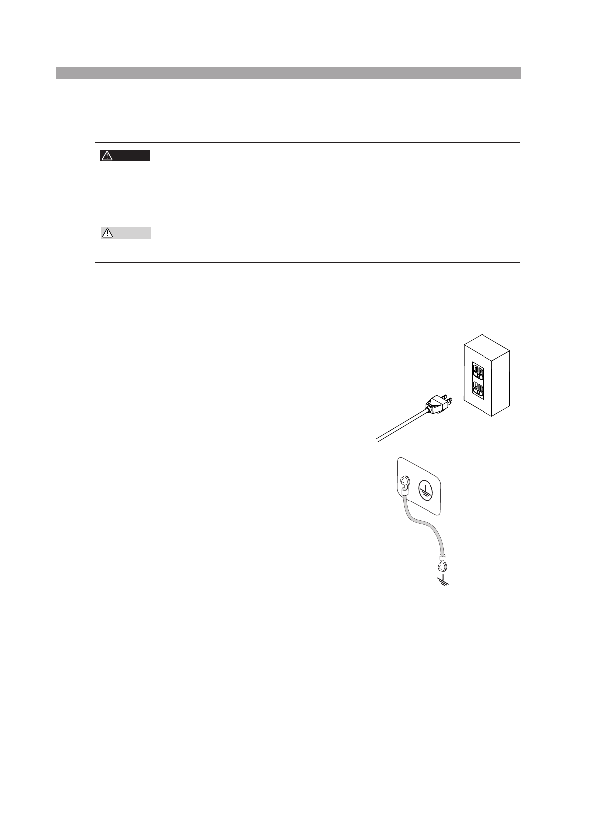
There are two types of methods in grounding the tester. Make sure to ground the
tester using either method.
1. Connect the power cord to a threepin power outlet with proper grounding.
Three-pin outlet with
proper grounding
2. Connect the grounding (earth) terminal on the rear panel to the earth
ground.
A qualified personal shall select and
create the wiring and make the
attachments.
Securely connect the wiring using
appropriate tools.
Appropriate
earth ground
Fig. 2-2 Grounding method
2-6 TOS5051A/5050A

3
3
Chap.3
WARNING
Chapter 3 Handling
Precautions
This chapter gives warnings and cautions you must observe when operating the
tester.
• The tester delivers a 5 kV test voltage which can cause electric shock.
When operating the tester, be extremely careful and observe the cautions,
warnings, and other instructions given in this chapter.
Handling Precautions
TOS5051A/5050A 3-1

3.1 Preparative Procedures
3.1.1 Wearing Insulation Gloves
When handling the tester, be sure to wear insulation gloves in order to protect yourself against high voltages. If you cannot obtain insulation gloves, please contact
Kikusui distributor/agent for them.
3.1.2 Grounding the Tester
Be sure to ground the tester. To do this, connect securely (using a tool) an earth line
to the protective grounding terminal on the rear panel of the tester. Unless the tester
is securely grounded, when the tester output is shorted to an earth line or to a conveyor or other device which is connected to an earth line or when it is shorted to the
AC line*
electric shock.
For a description of the grounding method, see section 2.6, “Grounding (Earth)”
(Page 2-6 ).
1
, the tester chassis can be charged up to the high voltage that can cause
DESCRIPTION
*1 The term “AC line” here means the line on which the tester is operating. That is
the line to whose outlet the power cord of the tester is connected. It may be of a
commercial AC power line or of a private-generator AC power line.
3.2 Warnings and Cautions When Operating the Tester
3.2.1 Before Turning ON the AC Input Power
Before turning on the AC input power, be certain that the TEST VOLTAGE control
knob is at the “0” position (fully counterclockwise position).
3.2.2 Connecting the Low Test Lead
For the connection method of the low test lead to the LOW output terminal of the
tester, see Fig. 3-1. Each time before using the tester, check that the low test lead is
not broken.
3-2 TOS5051A/5050A
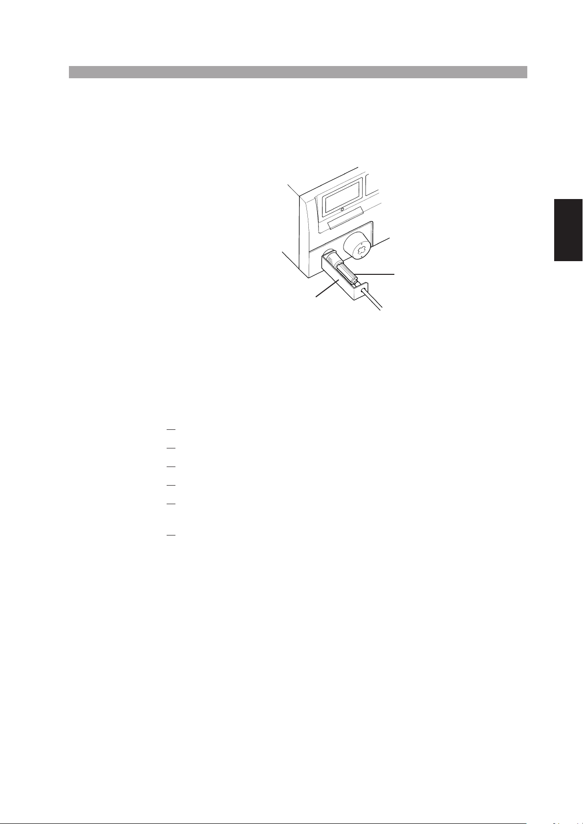
When connecting the tester to a DUT (device under test), connect the low test lead
first (and the high test lead next) and be sure that it securely connects the LOW output terminal of the tester to the corresponding terminal (chassis protective grounding terminal) of the DUT. If the connection is inadequate, entire DUT can be
charged up to a hazardous high voltage.
LOW output terminal
Test lead (black) to DUT
Install the lead clamp like this
Fig.3-1 Connecting the low-voltage test lead
Chap.3
3.2.3 Connecting the High Test Lead
Be sure to observe the order of lead connections--the low test lead first and the high
test lead next. To connect the tester to a DUT, proceed as follows:
Press the STOP switch.
1.
Check that the output voltmeter reading is “0”.
2.
Check that the DANGER lamp is OFF.
3.
Connect the high test lead to the HIGH VOLTAGE output terminal.
4.
Short the low and high test leads, and check that high voltage is not
5.
present.
Connect the tester to the DUT, with the low output lead first and high
6.
output lead next.
3.2.4 Before Changing Test Parameters
Before changing test parameters, press the STOP switch and be certain that the
TEST VOLTAGE control knob is at the “0” position (fully counterclockwise).
Handling Precautions
TOS5051A/5050A 3-3
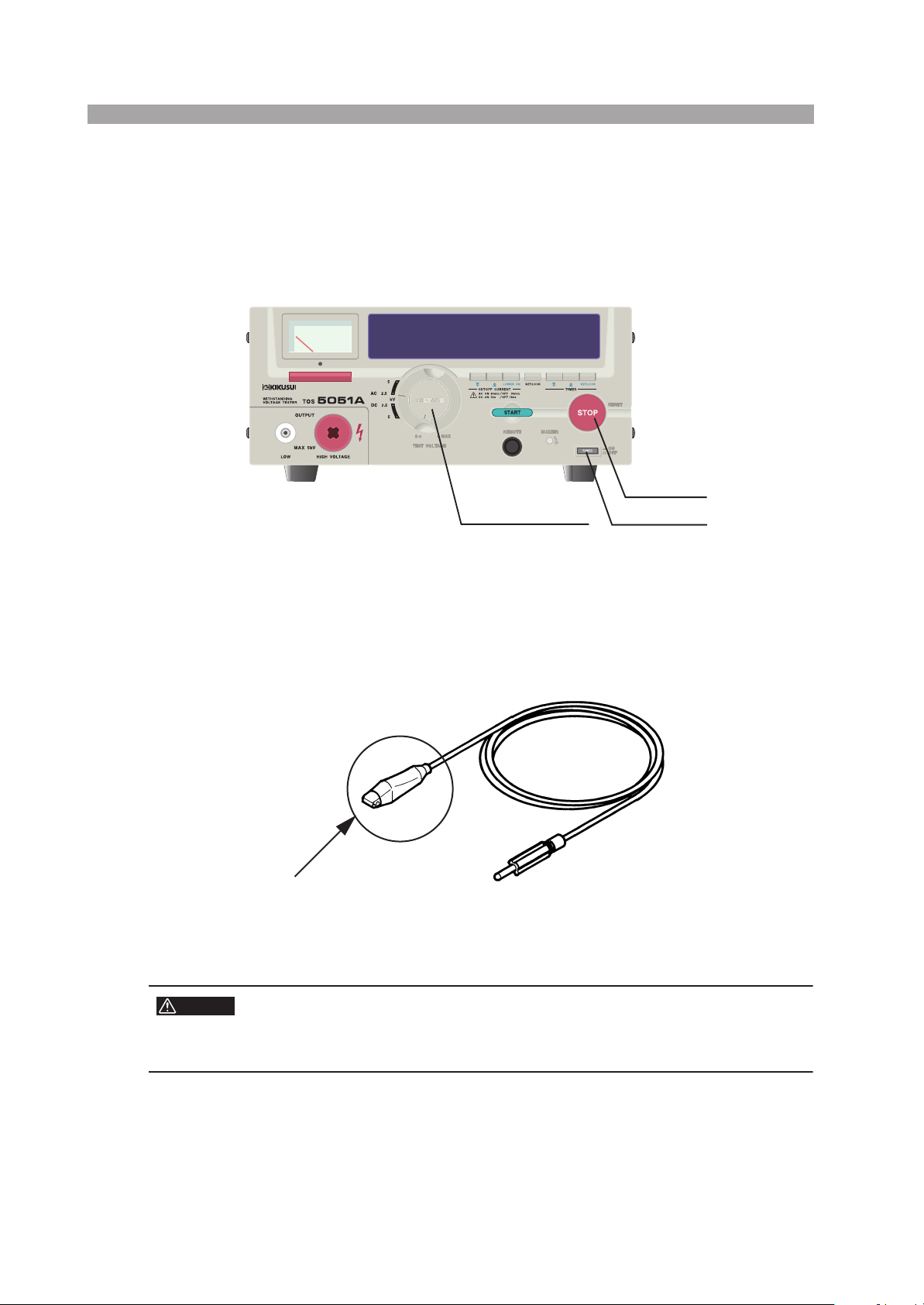
3.2.5 Precautions for Pausing Tests
When you pause a test, be sure to turn the TEST VOLTAGE control knob to the “0”
position (fully counterclockwise) and press the STOP switch. If you are not going to
resume the test soon or if you are leaving the test area, be sure to turn OFF the
switch.
STOP switch
TEST VOLTAGE control
POWER switch
Fig. 3-2 TOS5051A front panel
3.2.6 Items Charged Up to Dangerous High Voltages
WARNING
While the test is in progress (“TEST” is lit), touching a section charged with high
voltage near the DUT, test lead, probe, or output terminal is dangerous.
Alligator clip
(Never touch this area when test is in progress.)
Fig. 3-3 Test lead
• The vinyl sheaths of the alligator clips of the test leads which are supplied
with the tester does not have sufficient insulation for the high test voltages.
Never touch them when the test is in progress.
3-4 TOS5051A/5050A

3.3 Warnings after Turning OFF the Power
3.3.1 Check Items after Turning OFF the Power
If you have to touch the DUT, test leads, probes, and/or output terminals and their
vicinities for re-connections or other reasons, be sure of the following two matters:
• The output voltmeter indicates “0.”
• The DANGER lamp has turned OFF.
When you have tested the DUT with the DC output of the tester, the DUT will
remain charged at the high test voltage. For details, see section 3.3.2, “Residual
High Voltages (TOS5051A Only)” on Page 3-5 .
3.3.2 Residual High Voltages (TOS5051A Only)
Warning for Residual High Voltages
When you perform a test with the DC output, the DUT, test leads, probes, and output terminals and their vicinities are charged up to high voltages. Even after you
turn off the DC output, these voltages remain there for a period that depends on the
conditions of the test. Within this period, never touch the DUT, test leads, probes, or
output terminals or their vicinities to avoid electric shock.
When touching a section charged with high voltage, check the following:
Chap.3
Handling Precautions
• The output voltmeter indicates “0”.
• The DANGER lamp has turned OFF.
Checking the Discharge
The time necessary for the residual high voltage to be discharged varies depending
on test conditions--such as the properties of the DUT and the test voltage delivered
by tester.
Table 3-1 indicates the time it takes to discharge the internal capacitor when the
DUT is not connected (on the tester alone).
If a DUT is connected, the discharge time varies depending on the characteristics of
the DUT.
Table 3-1 indicates the time it takes to discharge when a DUT whose capacitance is
0.05 μF is connected to the tester.
TOS5051A/5050A 3-5

Table3-1 Discharge time
Test voltage Discharge time Note
TOS5051A alone
5 kV
DUT Approx. 50 ms
The tester has an internal circuit to discharge the residual high voltage of its output
circuit when the output is turned off. Do not disconnect the DUT from the tester
during a test. If you do, the residual high voltage on the DUT will remain undischarged for a long period.
Approx. 16 ms
Time until the output terminal voltage
of the TOS5051A attenuates to 30 V
Time until the DUT voltage attenuates to 30 V
3.4 Warnings for Remote Control
Be extremely careful when operating the tester in the remote control mode in which
the dangerous high test voltage is turned ON/OFF remotely. Provide protective
means as follows:
• Provide means to assure that the test setup does not output voltage
inadvertently (TEST state).
• Provide means to assure that no one can touch the DUT, test leads,
probes, output terminals and their vicinities when high voltage is being
output (TEST state).
3.5 Inhibitions
3.5.1 Inhibition of Rapid ON/OFF Repetitions
After turning OFF the power switch, be sure to allow several seconds or more
before turning it ON again. Do not repeat the operation of turning ON/OFF the
power switch rapidly. If you do, the protectors of the tester may not be able to render their protective functions properly. Do not turn OFF the power switch without
turning OFF the output switch first. Do this only in case of emergency.
3.5.2 Inhibition of Shorting to Earth Ground
Pay attention so that the high test voltage line is not shorted to a nearby AC line or
nearby devices (such as conveyors) which are connected to an earth ground. If it is
shorted, the tester chassis can be charged up to a hazardous high voltage.
Be sure to connect the protective grounding terminal of the tester to an earth line. If
this has been done correctly, the tester will not be damaged and its chassis will not
be charged up to the high voltage even when the HIGH output terminal is shorted to
the LOW output terminal.
For your safety, be sure to ground the tester. For a description of the grounding
method, see section 2.6, “Grounding (Earth)” (Page 2-6 ).
3-6 TOS5051A/5050A
 Loading...