

Kikusui TOS3200 Interface Manual

PART NO. IB026072
Nov. 2016
TOS3200
Communication
Interface Manual
Leakage Current Tester
1
2
3
App
Selecting
the Interface
SCPI language
Overview
Command
Reference

There are five TOS5300 Series Manuals listed as follows.
About the TOS3200 Manuals
Notations Used in This Manual
See
•Setup Guide
This manual is intended for first-time users of this product. It
provides an overview of the product and notes on usage. It
also explains how to set up the product for testing the DUT.
Always read this manual before using the product.
• Quick Reference
This manual explains Panel description and operation
briefly.
• Safety Information
This document contains general safety precautions for this
product. Keep them in mind and make sure to observe
them.
• User’s Manual (PDF)
This manual is intended for first-time users of this product. It
provides an overview of the product and notes on usage. It
also explains how to configure the product, operate the
product, perform maintenance on the product, and so on.
• Communication Interface Manual (this manual)
This manual contains details about remotely controlling the
tester using SCPI commands. This manual is provided on
the included CD-ROM.
The interface manual is written for readers with sufficient
basic knowledge of how to control measuring instruments
using a PC.
Trademarks
Company names and product names used in this manual are
generally trademarks or registered trademarks of the respective companies.
Copyright
Reproduction and reprinting of this operation manual, whole or
partially, without our permission is prohibited.
Both unit specifications and manual contents are subject to
change without notice.
© 2007 Kikusui Electronics Corporation
• The TOS3200 Leakage Current Tester is also simply
referred to as the TOS3200 in this manual.
• Equipment under test is also referred to as the EUT in this
manual.
• The word “PC” used in this manual is a generic term for personal computers and workstations.
• Touch current is simply referred to as TC in this manual.
• Protective conductor current is simply referred to as PCC in
this manual.
• The following markings are used in this manual.
TOS3200 Series Manuals are intended for users of the Leakage Current Tester and their instructors. Explanations are
given under the presumption that the reader has knowledge
about the electrical aspects of electrical safety testing.
If you find any misplaced or missing pages in this manual, it
will be replaced. If the manual gets lost or soiled, a new copy
can be provided for a fee. In either case, please contact your
Kikusui agent or distributor, and provide the “Kikusui Part No.”
given on the cover.
Every effort has been made to ensure the accuracy of this
manual. However, if you have any questions, or find any errors
or omissions, please contact your Kikusui agent or distributor.
After you have finished reading this manual, store it so that
you can use it for reference at any time.
Applicable firmware version of the
TOS3200
This manual applies to TOS32000s with firmware version
4.0x.
When making an inquiry about the product, please provide us
with the following information.
• Model (indicated at the top section on the front panel)
• Firmware version (See page 21.)
• Serial number (indicated at the bottom section on the rear
panel)
Indicates information that you should know.
Explanation of terminology or operation principle.
Indicates reference to detailed information.
>
Indicates the menu level of the item to be selected. The
menu item to the left of the > symbol is a higher level
menu.
SHIFT+key name (marked in blue)
Indicates an operation involving pressing the named key
(shown in blue) while the SHIFT key is held down.
SHIFT+Fx (F1 to F5)
Indicates an operation involving pressing a function key
(F1 to F5) while the SHIFT key is held down.
Before reading this manual
First read the User’s Manual, which includes information on
the product’s hardware, to avoid connecting or operating the
product incorrectly.
2 TOS3200

Contents
1
2
About the TOS3200 Manuals .................................................................................. 2
Notations Used in This Manual ............................................................................... 2
Contents................................................................................................................... 3
Selecting the Interface
Remote Control Overview ...................................................................................................... 6
VISA Library....................................................................................................... 7
Using the RS232C Interface................................................................................................... 8
Using the GPIB Interface...................................................................................................... 11
Using the USB Interface....................................................................................................... 12
SCPI language Overview
Overview of Messages ......................................................................................................... 14
SCPI Command Syntax ....................................................................................................... 14
Parameters........................................................................................................................... 17
3
Command Reference
Command Description in This Manual ................................................................................. 20
IEEE488.2 Common Commands ......................................................................................... 21
Selecting the Operation Mode.............................................................................................. 24
Setting the TC Measurement and PCC Measurement......................................................... 24
Setting the Connection Destination of the Measurement Terminal (TC measure-
ment only) ........................................................................................................ 24
Setting the Power Line Polarity........................................................................ 25
Setting the Single Fault Mode.......................................................................... 25
Setting the Lower Reference ........................................................................... 26
Setting the Upper Reference ........................................................................... 26
Setting the Test Time and Test Wait Time....................................................... 27
Setting the Measurement Network (TC measurement only)............................ 29
Setting the Measurement Mode....................................................................... 29
Setting the Measurement Range ..................................................................... 30
Querying the Settings ...................................................................................... 30
Saving and Recalling from the Panel Memory ................................................. 31
Executing the Test (Trigger Function) .................................................................................. 32
Saving and Querying the Test Result................................................................................... 37
Querying the Judgment Result (Common to All Tests).................................... 37
Saving the Result............................................................................................. 37
Querying the Result ......................................................................................... 38
Deleting the Test Results................................................................................. 39
Setting the Program Test ..................................................................................................... 40
Setting the Meter Mode Measurement ................................................................................. 45
Setting the Measurement Network (Current Measurement Only).................... 45
Setting the Measurement Mode....................................................................... 45
Setting the Measurement Range (Current Measurement Only) ...................... 46
Querying the Settings ...................................................................................... 46
TOS3200 3

Querying the Measured Value ............................................................................................. 47
Querying the Measured Current Flowing through Measurement Terminals A and
B ...................................................................................................................... 47
Querying the Measured Voltage between the Measurement Network Reference
Points............................................................................................................... 47
Querying the Measured Voltage between Measurement Terminals A and B (Volt-
age Measurement Only) .................................................................................. 48
Clearing the Maximum Measured Value.......................................................... 48
Voltage, current, and power of the EUT .......................................................... 49
Various Settings................................................................................................................... 50
Holding the Maximum Measured Current ........................................................ 50
Pass Judgment Hold Time .............................................................................. 50
Converting Measured Current Based on the Specified Line Voltage .............. 50
Setting the Safety Extra Low Voltage (SELV) ................................................. 51
Setting the Buzzer Volume .............................................................................. 51
Setting the Screen Brightness ......................................................................... 52
Setting the Time .............................................................................................. 52
Turning the Power Line to the EUT On/Off...................................................... 53
Showing/Hiding Communication Errors ........................................................... 53
Releasing the Protection Status ...................................................................... 53
Other Settings.................................................................................................. 54
Status Register and Status Report Function........................................................................ 56
IEEE488.2 Register Model................................................................................................... 58
Status Byte Register........................................................................................ 58
Event Status Register...................................................................................... 59
SCPI Register Model............................................................................................................ 60
OPERation Status Register ............................................................................. 60
QUEStionable Status Register ........................................................................ 62
Preset Status ................................................................................................... 63
Tutorial ................................................................................................................................. 64
TC Measurement/PCC Measurement (MANUAL TEST)................................. 64
Program Test (AUTO TEST) ........................................................................... 65
Meter Mode Measurement .............................................................................. 66
Appendix
A A List of Messages ....................................................................68
B A List of Errors ...........................................................................74
C Processing Time of Main Commands.........................................77
D A List of Default Settings ...........................................................78
Initializing the TOS3200 .................................................................................. 78
Default Values of the Panel Memory ............................................................... 80
INDEX.......................................................... 82
4 TOS3200

リモ┃トコントロ┃ル
Selecting the Interface
This chapter gives an overview of the remote control function
and explains interface setting.

Remote Control Overview
See
In addition to using the front panel, the TOS3200 can be controlled remotely using the following interfaces (equipped as standard).
• RS232C interface
• GPIB interface
•USB interface
The GPIB, RS232C, and USB interfaces cannot be used simultaneously.
The remote interface complies with IEEE Std 488.2-1992 and SCPI Specification 1999.0.
p. 14
Use the SCPI commands only after you have understood the SCPI command syntax for the
TOS3200.
If the TOS3200 is operating under remote control, the RMT LED on the front panel will illuminate. To switch from the remote mode to the local mode (panel operation) from the panel,
press the LOCAL key.
Instrument Interface Standards
The TOS3200 conforms to the following standards.
• IEEE Std 488.2-1992 IEEE Standard Codes, Formats, Protocols, and Common Com-
mands For Use With IEEE Std 488.1-1987
• IEEE Std 488.1-1987 IEEE Standard Digital Interface for Programmable Instrumentation
• Standard Commands for Programmable Instruments (SCPI) version 1999.0
• Universal Serial Bus Specification Rev 2.0
• Universal Serial Bus Test and Measurement Class Specification (USBTMC) Rev 1.0
• Universal Serial Bus Test and Measurement Class, Subclass USB488 Specification
(USBTMC-USB488) Rev 1.0
6 TOS3200

Remote Control Overview
VISA Library
If you are using a VISA library (VISA COM) for the I/O library, the VISA library must be
installed on the PC.
A device driver supporting USB T&M Class (USBTMC) is required to control the TOS3200
through the USB interface. The USBTMC driver is automatically installed by the VISA library.
VISA (Virtual Instrument Software Architecture) is a specification for standard software for
connecting instruments that was defined by the VXIplug&play Systems Alliance.
One of the VISA libraries (driver software implemented in compliance with the VISA specifications) below is necessary.
Older version of VISA libraries does not support USB. USB functions cannot be used on Windows 95 or Windows NT 3.5x or 4.0.
• NI-VISA by National Instruments (Ver. 3.0 or later, Ver. 3.2 or later for Windows 2000 and
• Agilent VISA by Agilent Technologies (Agilent IO Libraries M01.00 or later)
• KI-VISA Ver. 3.0.0 or later
KI-VISA is Kikusui original VISA library compatible with VXIplug&play VISA Specifications
3.0. The latest version can be downloaded from Kikusui website (http://www.kikusui.co.jp/en/
download/). KI-VISA is not required if NI-VISA or Agilent VISA is already installed.
1
Selecting the Interface
Windows XP)
TOS3200 7
Using the RS232C Interface
1
2
3
4
5
6
7
8
9
1
2
3
4
5
6
7
8
9
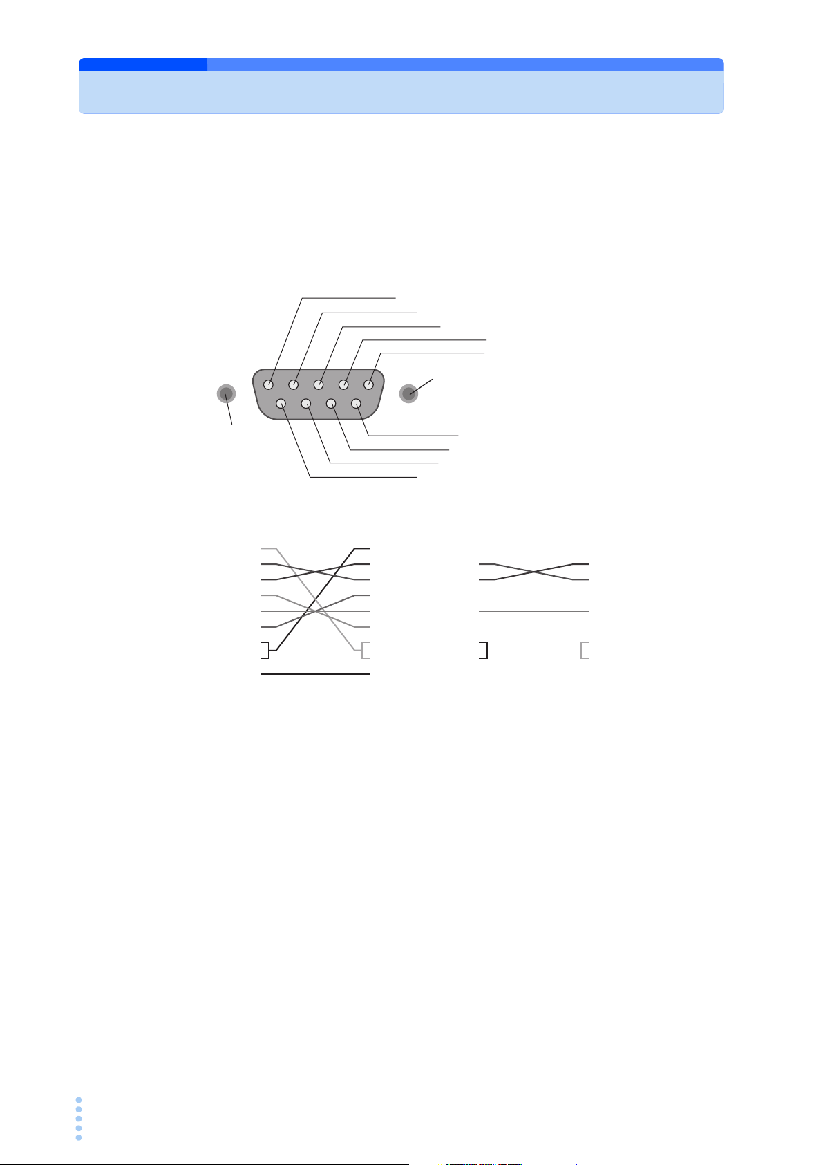
D-sub 9 pin female
D-sub 9 pin female
Cross cable example 1
1
2
3
4
5
6
7
8
9
1
2
3
4
5
6
7
8
9
D-sub 9 pin female
D-sub 9 pin female
Cross cable example 2
#4-40UNC
inch screw
#4-40UNC
inch screw
1: CD (carrier detect)
2: RXD (receive data)
3: TXD (transmit data)
4: DTR (data terminal ready)
5: GND (signal ground)
6: DSR (data set ready)
7: RTS (request to send)
8: CTS (clear to send)
9: RI (ring indicator)
Facing the TOS3200 rear panel
The RS232C port on the TOS3200 is a standard D-sub 9-pin male connector.
Check that the POWER switches of the TOS3200 and the PC are off, and connect the
TOS3200 to the PC using a standard cross cable (null modem cable).
Use a D-sub 9-pin female-to-female AT type for the cross cable. Fig. 1-1shows the connector
pin assignments.
The TOS3200 does not use hardware handshaking (cross cable example 2).
8 TOS3200
Fig. 1-1 9-pin AT type connector

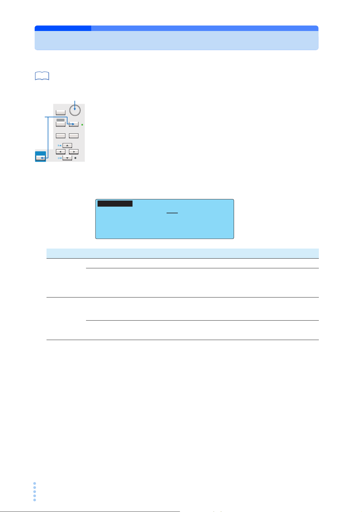
Using the RS232C Interface
SHIFT
SYSTEM
RECALL ENTER
STORE
MANUAL
I / FEDIT
AUTO
RMT
PREV NEXT
1
2
SELECT X–FLOW STOPBAUD DATA
I/F
SELECT:RS232C
BAUDRATE : 19200
ERR TRACE : OFF
DATA BITS : 8 X–FLOW : ON
TALK MODE : ON STOP BITS : 1
INTERFACE
Press the I/F (SHIFT+SYSTEM) key to display the interface setup screen
1
(INTERFACE).
Press the SHIFT+F1 key or turn the rotary knob to select RS232C.
2
Set the RS232C protocol and communication error trace function.
3
The settings of the communication error trace function are common to all interfaces.
You cannot set it separately for each interface.
Turn the power off and turn it back on.
4
The settings are fixed. The communication error trace function is set even if you do not
turn the power off.
Item Description Panel operation
I/F SELECT Sets the interface that you are going to use. F1 key
USB USB (see p. 12 to use the USB.)
SHIFT+F1 keyRS232C RS232C
GPIB GPIB (see p. 11 to use the GPIB.)
SPEED Sets the baud rate. F2 key
Baud rate 38400, 19 200, or 9 600 Rotary knob
DATA BITS Sets the data length. F3 key
Bit 8 or 7 Rotary knob
X-FLOW
STOP BITS
Sets the flow control.(see p. 10 for details on the flow control.)
ON Enable the flow control. Rotary knob
OFF Disable the flow control.
Sets the stop bit.
F4 key
F5 key
1
Selecting the Interface
Bit 2 or 1 Rotary knob
TALK MODE Sets the talk mode. (see p. 10 for details on the talk mode.) SHIFT+F3 key
ON Respond automatically
OFF No output response
Sets the communication error trace function. (Common to all interfaces.)
ERR TRACE
TOS3200 9
Sets whether or not to display error numbers on the screen when there are
errors in the error queue.
ON Enable the error number display.
OFF Disable the error number display.
SHIFT+F3 key
SHIFT+F4 key
SHIFT+F4 key

Using the RS232C Interface
Resume transmission
DC3
TXD
TOS3200
RXD
The RS232C terminal must pause transmission
within 10 characters after receiving DC3.
Within 10
characters
DC1
Pause
Flow control
Use flow control for RS232C communication. DC (device control) codes are used as control
codes.
Transmission/reception may not work correctly through unilateral transmission.
Code Function ASCII code
DC1 (Xon)
DC3 (Xoff)
Transmission
request
Transmission
stop request
11H
13H
Fig. 1-2 RS232C terminal and transmission control of the TOS3200
Talk mode
Processing on the PC can be reduced by using talk mode, because commands do not need
to be sent from the PC. If you connect a serial printer to the TOS3200, the test log can be
printed directly.
If talk mode is turned on, the TOS3200 cannot be controlled from the PC. If you want to
remotely control the TOS3200 from a PC, be sure to turn talk mode off.
• Talk mode off (default)
Responds only to the commands from the PC.
• Talk mode on
Responds automatically at the start and end of the test.
Response when a test is started: START
Response when a test ends: PROTECT, PASS, U_FAIL, L_FAIL, C_FAIL (CONTACT
FAIL), or STOP
Break signal
The break signal functions as a substitute for the IEEE488.1 dcl/sdc (Device Clear, Selected
Device Clear) message.
10 TOS3200

Using the GPIB Interface
SHIFT
SYSTEM
RECALL ENTER
STORE
MANUAL
I / FEDIT
AUTO
RMT
PREV NEXT
1
2
SELECT ADDRESS
I/F SELECT:GPIB
GPIB ADDRESS : 3 ERR TRACE : OFF
INTERFACE
Use a standard IEEE488 cable to connect the TOS3200 to the PC.
Press the I/F (SHIFT+SYSTEM) key to display the interface setup screen
1
(INTERFACE).
Press the SHIFT+F1 key or turn the rotary knob to select GPIB.
2
Set the GPIB address and communication error trace function.
3
The settings of the communication error trace function are common to all interfaces.
You cannot set it separately for each interface.
Turn the power off and turn it back on.
4
The settings are fixed. The communication error trace function is set even if you do not
turn the power off.
1
Selecting the Interface
Item Description Panel operation
I/F SELECT Sets the interface that you are going to use. F1 key
USB USB (see p. 12 to use the USB.)
SHIFT+F1 keyRS232C RS232C (see p. 8 to use the RS232C.)
GPIB GPIB
GPIB
ADDRESS
ERR TRACE
Sets the GPIB address. F2 key
Address Selectable range: 1 to 30 Rotary knob
Sets the communication error trace function. (Common to all interfaces.)
If an error is present in the error queue, the error number will be displayed
on the screen.
ON Enable the error number display.
OFF Disable the error number display.
SHIFT+F4 key
SHIFT+F4 key
GPIB function
Function Subset Description Function Subset Description
Source handshaking SH1 Full capability Remote local RL1 Full capability
Acceptor handshaking AH1 Full capability Parallel polling PP0 No capability
Talker T6 Function available Device clear DC1 Full capability
Listener L4 Function available Device trigger DT1 Full capability
Service request SR1 Full capability Controller C0 No capability
Electrical interface E1 Open collector driver
TOS3200 11
Service request
Service request and serial polling functions are implemented.
Using the USB Interface
See
SHIFT
SYSTEM
RECALL ENTER
STORE
MANUAL
I / FEDIT
AUTO
RMT
PREV NEXT
1
2
p. 7
A device driver supporting USB T&M Class (USBTMC) is required to control the TOS3200
through the USB interface. The USBTMC driver is automatically installed by the VISA library.
Press the I/F (SHIFT+SYSTEM) key to display the interface setup screen
1
(INTERFACE).
Press the SHIFT+F1 key or turn the rotary knob to select USB.
2
You can check the vendor ID, product ID, and serial number of the TOS3200.
Sets the communication error trace function.
3
The settings of the communication error trace function are common to all interfaces.
You cannot set it separately for each interface.
Turn the power off and turn it back on.
4
The settings are fixed. The communication error trace function is set even if you do not
turn the power off.
INTERFACE
VENDER I D : 0x0B3E
PRODUCT I D : 0 x1 010
SELI AL No. :
SELECT
I/F
SELECT:USB
ERR TRACE : OFF
Item Description Panel operation
I/F SELECT Sets the interface that you are going to use. F1 key
USB USB
SHIFT+F1 keyRS232C RS232C (see p. 8 to use the RS232C.)
GPIB GPIB (see p. 11 to use the GPIB.)
Sets the communication error trace function. (Common to all interfaces.)
ERR TRACE
If an error is present in the error queue, the error number will be displayed
on the screen.
ON Enable the error number display.
OFF Disable the error number display.
SHIFT+F4 key
SHIFT+F4 key
USB function
Complies with USB Specification 2.0.
Complies with USBTMC Specification 1.0 and USBTMC-USB488 Specification 1.0.
Data rate: 12 Mbps maximum (full speed).
VID (vendor ID): 0x0B3E
PID (product ID): 0x1010.
Service request
Service request and serial polling functions are implemented.
12 TOS3200

リモ┃トコントロ┃ル
SCPI language Overview
This chapter explains the SCPI command structure, syntax,
and parameters.

Overview of Messages
The information that is exchanged between the PC and the TOS3200 is called a message.
The TOS3200 uses the SCPI language for the messages.
There are two types of messages, commands that are sent from the PC to the TOS3200 and
responses that are sent from the TOS3200 to the PC.
Commands are used to execute functions of the TOS3200, change settings, and query settings and statuses. Responses return the settings and statuses of the TOS3200.
SCPI Command Syntax
Command hierarchy
The SCPI is an ASCII-based command language designed for test and measurement
devices. The command hierarchy is structured around the common root or node, which is the
construction block of the SCPI sub system. A command consists of a program header,
parameters, and punctuations.
The hierarchy is explained using the SYSTem subsystem as an example.
Program header Parameter Node hierarchy
:SYSTem Root node
:BEEP 2nd level
:VOLume 3rd level
:FAIL <numeric> 4th level
:PASS <numeric> 4th level
:DATE <nrf>,<nrf>,<nrf> 2nd level
:ERRor 2nd level
[:NEXT] <code>, “<description>” 3rd level
A higher node is separated from a lower node using a colon (:).
14 TOS3200

SCPI Command Syntax
Command syntax
This manual denotes SCPI commands using the following format.
(Example)
SYSTem:BEEP:VOLume:FAIL {<numeric>|MINimum|MAXimum}
• There are two forms of SCPI commands, the long form in which the command is written
out in its entirety and the short form in which the letters written in lowercase are omitted.
SCPI commands can be sent in the long form or short form.
• SCPI commands are not case sensitive. VOL, Vol, and vol are all accepted as short
forms of VOLTage.
VOLUME, Volume, volume are all accepted as long forms.
• A space is required between the program header section and the parameter section.
• Multiple parameters, when available, are concatenated using commas.
• Compound commands can be created by concatenating two commands with a semicolon.
(Example)
SYSTem:BEEP:VOLume:FAIL MINimum;PASS MINimum
This compound command is the same as entering the following two commands.
SYSTem:BEEP:VOLume:FAIL MINimum
SYSTem:BEEP:VOLume:PASS MINimum
The first command, SYSTem:BEEP:VOLume:FAIL, sets the path to SYSTem:BEEP:VOLume. Therefore, SYSTem:BEEP:VOLume, can be omitted in the second command.
An error occurs if a node that is not defined in the current path (except FAIL and PASS) is
designated.
2
SCPI language Overview
• A colon is required between program headers.
• Commands of different subsystems can be concatenated using colons and semicolons.
(Example)
SYSTem:CONFigure:PHOLd MINimum;:MEASure:CURRent?
This compound command contains two root nodes, SYSTem and MEASure.
If the second or subsequent command starts with a colon, the path specified by the previous
command will be cleared.
• The maximum number of characters that can be transmitted in a single line is 128.
Special symbols and characters
Special symbols and characters used in this manual to describe SCPI commands are defined
as indicated in the following.
Symbols or
characters
< >
{ }
[ ]
Description
Characters strings inside the < and > symbols indicate program data.
Do not include these symbols in the actual program.
Characters and numbers delimited by “|” in braces indicate that one of
the items is to be selected.
Do not include the braces in the actual program.
Characters strings inside brackets indicate optional data.
When option data is not sent with the program, the default value will
be sent. Do not include the brackets in the actual program.
TOS3200 15

SCPI Command Syntax
See
Query
The device settings or status can be queried.
To make a query, add a question mark at the end of the program header section. If a query
has parameters, enter a space after the question mark followed by the parameters.
(Example)
CURRent? MIN
When transmitting two queries in separate lines, read the response to the first query before
transmitting the second line. If you send two lines of query commands at once, an incomplete response may be received.
String termination
All commands must be terminated using a valid terminator.
The available terminators are <line feed> (ASCII 0x0A) and EOI (end-or-identify).
Either one can be used as a terminator.
Because EOI is not available on the RS232C, be sure to use <line feed>.
If a command string is terminated, the path will be reset to the root level.
p. 21
CR (ASCII 0x0D) is not a terminator.
Common commands
The IEEE-488.2 and SCPI standards contain a set of common commands for reset, self-test,
and other functions. These common commands always start with an asterisk. The commands
may have one or multiple parameters.
16 TOS3200

Parameters
The parameter format of SCPI is derived from the program parameter format defined in IEEE
488.2.
The representation system of the program data that is used on the TOS3200 is indicated
below.
Non-numeric parameters
The TOS3200 uses the following three types of non-numeric parameters.
2
Symbols or
characters
Character string
data
(String)
Character data
(Character)
Boolean data
(Boolean)
Description
Used when a series of ASCII characters are requested.
Be sure to enclose a string in single quotations or double quotations.
The start and end quotation marks must match.
(Example) NETWork "A"
If you want to use a quotation mark as a part of the string, enter two
quotation marks consecutively (with no characters in between). ASCII
codes 20H to 7EH can be used.
Used when only a limited number of values is available for the program setting.
Responses are returned in the short form.
(Example) CURRent:RANGe:SELect {LOW|MEDium|HIGH}
Expresses a 1 or 0 condition or an ON or OFF condition.
Responses are returned as 1 or 0.
(Example) SYSTem:CONFigure:TRACe {ON|OFF|1|0}
Numeric parameters
The TOS3200 uses the following five types of numeric parameters.
Symbols or
characters
NR1
NR2
NR3
NRf NRf is a generic term that includes NR1, NR2, and NR3.
Numeric
Description
Represents an integer.
Represents a real number (floating point).
Represents a real number (exponential).
The value +3.80000+E02 is returned for the response data 380. The
number of digits to the right of the decimal is 5.
Represents a decimal point, optional sign, and measurement unit.
The numeric representation syntax is the same as NRf.
MINimum and MAXimum are available as substitutes for declaring
certain values.
Units such as V, A, and S can also be used in a numeric parameter.
If a value that cannot be assigned is entered, the device will round the
value to the closest possible value.
(Example) SYSTem:BEEPer:VOLume:FAIL 20
The range of values for SYST:BEEP:VOL:FAIL is 0 to 10. Thus, 10 is
set even if 20 is specified.
*1
*1
*1
SCPI language Overview
*1. Details are given in the IEEE 488.2 Standard Digital Interface for Programmable Instrumen-
tation.
TOS3200 17

Parameters
Special form numeric parameter
The special form numeric parameters MINimum and MAXimum can be used as substitutes
for limit values when the parameter is numeric.
In the example below, the buzzer volume for FAIL judgments is to the minimum value.
SYSTem:BEEPer:VOLume:FAIL MINimum
The minimum and maximum values can be inquired for most parameters using queries.
CURRent:LIMit:UPPer? MAX
Measurement unit
Below are the default measurement units. Commands will be accepted even if measurement
units are not specified.
• A (current)
• V (voltage)
• W (wattage)
• S (second)
The following optional prefixes are supported. To enter “µ” in the parameter, use “U” instead.
• M (milli)
•U (micro)
The unit symbols in the International System of Units contain lowercase characters. The
IEEE standard uses uppercase characters. SCPI commands are not case sensitive.
18 TOS3200

リモ┃トコントロ┃ル
Command Reference
This chapter explains details of each command and registers.
Command Description in This Manual
Touch current measurement
command
Protective conductor current
measurement command
The commands are given in the
long form.
The lower-case section can be
omitted.
The section enclosed by braces ([])
can also be omitted.
The selectable range is given.
Optional symbols such as m and µ
can also be used.
The unit for the value. The unit can
be omitted.
This command is affected if *RST
is sent, and the setting changes to
the value indicated in Table 7-9.
The test time is changed to 10 s if
*RST is sent.
Specify MAX to set the maximum value.
Specify MIN to set the minimum value.
The representation system of the value
that is returned when a query is sent.
Attach the value you want to specify after
the command and send the command.
To set the test time to 20 s in the touch
current measurement, send TC:TIM 20.
Commands with these marks will be affected if
*RST or *RCL is sent. The settings will be changed
to the default values indicated on page 196.
The test time will be changed to 10 s if *RST is sent.
** RCLRCL* RSTRST
TC:TIM / PCC:TIM
Set the test time.
TC:TIM:ST This setting is valid when TC:TIM:STAT or PCC:TIM:STAT is on.
Command
[SENSe:] TC :TIMer { <numeric> | M IN|MAX }
[SENSe:]T C :TIMer? {MIN|MAX}
[SENSe:] PCC :TIMer { <numeric> | M IN|MAX }
[SENSe:] PCC :TIMer? {MIN|MAX}
Parameter
Value:
1 to 999
(The default value is 10.)
Unit:
S
Table A-4 shows the setting that is specified when *RST or *RCL is sent.
Response
Returns the test time in the <NR3> form in response to TC:TIM? or PCC:TIM?.
The parameters are listed.
In the case of this command, the
parameter is numeric. In addition to
specifying the desired value, you can
specify the minimum or maximum value.
See
This manual describes the commands in the following manner.
Command items and reference pages
Item
Page
Command syntax 14
Parameter 17
Unit 18
Default values 78
Query 16
Representation system 17
List of messages 68
List of errors 74
20 TOS3200

IEEE488.2 Common Commands
See
See
See
*CLS
Clears all event registers including the status byte, event status, and error queue.
p. 56
Command *CLS
*ESE
p. 59
Command *ESE <NR1>
Sets the event status register that is counted by the event summary bit (ESB) of the status
byte.
*ESE?
Parameter
3
Parameter Value: 0 to 255
An SCPI error (-222, “Data out of range”) occurs if outside the range.
(Example) When *ESE 16 is transmitted, bit 4 of the event status enable register is set. Each
time the execution error bit (bit 4) of the event status register is set, the summary
bit (ESB) of the status byte is set.
Response Returns the value of the event status enable register in the <NR1> form.
*ESR
p. 59
Command *ESR?
Response
Queries the event status register. Registers that are read are cleared.
Returns the value of the event status register in the <NR1> form and clears the register.
*IDN
Queries the model name, serial number, and firmware version of the TOS3200.
Command *IDN?
Command Reference
Response
TOS3200 21
The response to *IDN? is indicated below.
(Example) For TOS3200 with a serial number AB123456 and firmware version 1.00
Returns KIKUSUI,TOS3200,AB123456,1.00.

IEEE488.2 Common Commands
See
See
See
*OPC
Sets the OPC bit (bit 0) of the event status register when the processing of all commands
Section 12.5.3 in
IEEE 488.2-1992
Command *OPC
standing by is complete.
*OPC?
Response
Returns 1 when the processing of all commands standing by is complete.
*OPT
Queries the option (HP21-TOS only) that is installed in the TOS3200.
Command *OPT?
Response
If the HP21-TOS is installed, “HP21-TOS” is returned. Returns 0 if the option is not installed.
*RCL
Aborts the measurement operation and reads the contents stored in memory. The operation
is the same as MEM:RCL.
Command *RCL <NR1>
Parameter Value: 0 to 99 Memory number
An SCPI error (-222, “Data out of range”) occurs if outside the range.
*RST
p. 78
Aborts the measurement operation and initializes the TOS3200 to factory default condition.
For the commands that are affected by *RST, see “Default values.
Command *RST
*SAV
p. 78
Command *SAV <NR1>
Parameter Value: 0 to 99 Memory number
Stores the present TOS3200 settings to memory. The operation is the same as MEM:SAV.
The settings that are stored are the same as those recalled using the *RCL command. See
“Default values.
An SCPI error (-222, “Data out of range”) occurs if outside the range.
*SRE
Sets the service request enable register.
The service request enable register is used to select the summary messages in the status
byte register that will be able to perform service requests.
To clear the service request enable register, send *SRE 0. If the register is cleared, service
requests cannot be generated by status information.
22 TOS3200

Command *SRE <NR1>
See
See
See
*SRE?
Parameter Value: 0 to 255
An SCPI error (-222, “Data out of range”) occurs if outside the range.
(Example) Sending *SRE 8 sets bit 3 of the service request enable register. Each time the
summary bit (bit 3) of the QUEStionable status register in the status byte is set, a
service request message is generated.
IEEE488.2 Common Commands
Response Returns the value of the service request enable register in the <NR1> form.
*STB
p. 58
Command *STB?
Response
*TRG
Section 10.37 in
IEEE 488.2-1992
Command *TRG
Queries the contents of the status byte register and the MSS (master summary status) message.
The response is the same as serial polling only with the exception that the MSS message
appears in place of the RQS message in bit 6.
Returns the value of the status byte register and the MSS message (bit 6) in <NR1> form.
Trigger command.
This is a substitute command for the IEEE488.1 get message (Group Execute Trigger).
If the TOS3200 is not in a condition to accept triggers, an SCPI error (-211,“Trigger ignored”)
will occur.
3
Command Reference
*TST
Section 10.38 in
IEEE 488.2-1992
Command *TST?
Response
*WAI
Command *WAI
Executes a self-test. Use SYST:ERR? to query the errors that occurred.
Returns 0 if there are no errors. If there are, the error code is returned.
Prevents the TOS3200 from executing subsequent commands until all operations in standby
are complete.
TOS3200 23

Selecting the Operation Mode
** RCLRCL* RSTRST
*
RCL*
RST
FUNC
Sets the operation mode.
Command [SENSe:]FUNCtion[:ON] "{CURRent|PCC|TC|VOLTage|AUTO}"
[SENSe:]FUNCtion[:ON]?
Parameter “CURRent”Current measurement (Meter Mode)
“PCC” PCC Measurement Mode
“TC” TC Measurement Mode (default)
“VOLTage” Voltage measurement (Meter Mode)
“AUTO” Program test
Response Returns the operation mode in the <string> form.
If the TOS3200 is displaying the SYSTEM or INTERFACE screen, ”” will be returned.
Setting the TC Measurement and PCC Measurement
The commands with “TC” in the second-level node are for TC measurement. Commands with
“PCC” are for PCC measurement.
Setting the Connection Destination of the Measurement Terminal (TC measurement only)
TC:PROB
Sets the connection destination (PROBE) of measurement terminals A and B.
Command [SENSe:]TC:PROBe {ENCPE|ENCENC|ENCLIV|ENCNEU}
[SENSe:]TC:PROBe?
Parameter Value: ENCPE Between the enclosure and earth (default)
ENCENC Between two enclosures
ENCLIV Between the enclosure and power line (live)
ENCNEU Between the enclosure and power line (neutral)
Response Returns the connection destination of the measurement terminal in the <character> form.
RST
*
RCL
24 TOS3200

Setting the TC Measurement and PCC Measurement
** RCLRCL* RSTRST
** RCLRCL* RSTRST
Setting the Power Line Polarity
TC:POL / PCC:POL
Sets the polarity (POL) of the power line supplied to the EUT. If you set the connection destination of the measurement terminal to between the enclosure and power line, this command
will be invalid.
Command [SENSe:]TC:POLarity {NORMal|REVersed}
[SENSe:]TC:POLarity?
[SENSe:]PCC:POLarity {NORMal|REVersed}
[SENSe:]PCC:POLarity?
Parameter Value: NORM Normal phase connection (default)
REV Reverse phase connection
Response Returns the polarity of the power line in the <character> form. If the connection destination
of the measurement terminal is set to between the enclosure and power line, NA is returned.
3
Command Reference
Setting the Single Fault Mode
TC:COND / PCC:COND
Sets the single fault mode (COND). If you set the connection destination of the measurement
terminal to between the enclosure and power line, this command will be invalid.
Command [SENSe:]TC:CONDition {NORMal|FLTNEU|FLTPE}
[SENSe:]TC:CONDition?
[SENSe:]PCC:CONDition {NORMal|FLTNEU}
[SENSe:]PCC:CONDition?
Parameter Value: NORMal Normal condition (default)
FLTNEU Power line (neutral) disconnected condition
FLTPE Earth line disconnected condition (TC Measurement Mode only)
Response Returns the single fault mode in the <character> form. If the connection destination of the
measurement terminal is set to between the enclosure and power line, NA is returned.
TOS3200 25
Setting the TC Measurement and PCC Measurement
*
RCL*
RST
*
RCL*
RST**
RCL*
RST
Setting the Lower Reference
TC:LIM:LOW / PCC:LIM:LOW
Sets the lower limit of the judgment reference (lower reference). This setting is valid when
TC:LIM:LOW:STAT or PCC:LIM:LOW:STAT is on.
For TC measurement, the setting varies depending on the measurement network and current
measurement mode settings. For PCC measurement, the setting varies depending on the
current measurement mode setting.
RST
*
RCL
Command [SENSe:]TC:LIMit:LOWer[:LEVel] {<numeric>|MIN|MAX}
[SENSe:]TC:LIMit:LOWer[:LEVel]? {MIN|MAX}
[SENSe:]PCC:LIMit:LOWer[:LEVel] {<numeric>|MIN|MAX}
[SENSe:]PCC:LIMit:LOWer[:LEVel]? {MIN|MAX}
Parameter Value: Varies depending on the current measurement mode and the measurement net-
work settings. (The default value is 30 µ.)
Unit: A
Response Returns the lower reference in the <NR3> form.
■ Selectable range of LOWER
TC measurement PCC measurement
MODE NTWK A, B, B1,C NTWK D, E NTWK F NTWK G
DC, RMS 30 µA to 30.0 mA 30 µA to 30.0 mA 30 µA to 20.0 mA 30 µA to 15.0 mA 30 µA to 30.0 mA
PEAK 50 µA to 90.0 mA 50 µA to 45.0 mA 50 µA to 30.0 mA 50 µA to 22.5 mA 50 µA to 90.0 mA
TC:LIM:LOW:STAT / PCC:LIM:LOW:STAT
Sets whether to perform judgment with respect to the lower reference. Set the lower reference using TC:LIM:LOW or PCC:LIM:LOW.
Command [SOURce:]TC:LIMit:LOWer:STATe {ON|OFF|1|0}
[SOURce:]TC:LIMit:LOWer:STATe?
[SOURce:]PCC:LIMit:LOWer:STATe {ON|OFF|1|0}
[SOURce:]PCC:LIMit:LOWer:STATe?
Parameter Value: ON (1) Enable the judgment
OFF (0) Disable the judgment (default)
Response Returns the whether to perform judgment with respect to the lower reference in the <NR1> form.
Setting the Upper Reference
TC:LIM:UPP / PCC:LIM:UPP
Sets the upper limit of the judgment reference (upper reference). This setting is valid when
TC:LIM:UPP:STAT or PCC:LIM:UPP:STAT is on.
For TC measurement, the setting varies depending on the measurement network and current
measurement mode settings. For PCC measurement, the setting varies depending on the
current measurement mode setting.
RST
RST
*
RCL
RCL
26 TOS3200
 Loading...