

Kikusui RC04-PCR-LA Operation Manual
Part No. Z1-002-902, IA002963
Jan 2007
OPERATION MANUAL
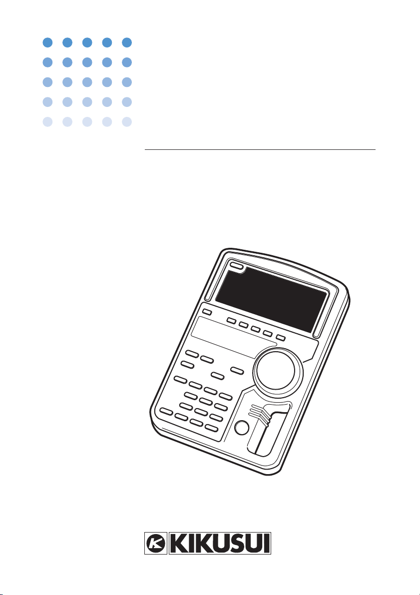
REMOTE CONTROLLER
PCR-LA Series
RC04-PCR-LA

Use of Operation Man ual
Please read through and understand this Operation Manual before operating the prod uct. After reading, al w ays k eep the manual nearby so that you may refer to it as
needed. When mo ving the product to another location, be sure to bring the manual as
well.
If you fi nd an y incorrectly arranged or missing pages in this manual, the y will be
replaced. If the manual it gets lost or soiled, a ne w cop y can be pro vided for a fee. In
either case, please contact Kikusui distrib utor/agent, and pro vide the “Kikusui P art
No. ” gi v en on co v er .
This manual has been prepared with the utmost care; ho we v er , if you ha v e an y ques tions, or note an y errors or omissions, please contact Kikusui distrib utor/agent.
Reproduction and reprinting of this operation manual, whole or partially , without our
permission is prohibited.
Both unit specifi cations and manual contents are subject to change without notice.
© 2003-2007 Cop yright Kikusui Electronics Corporation
Printed in Japan
F
Saf ety Symbols
or the safe use and safe maintenance of this product, the
following symbols are used throughout this manual and on
the product. Understand the meanings of the symbols and
observe the instructions they indicate (the choice of sym
bols used depends on the products).
Indicates that a high voltage (over 1000 V) is used here.
OR
Touching the part causes a possibly fatal electric shock.
If physical contact is required by your work, start work
only after you make sure that no voltage is output here.
-
DANGER
WARNING
CAUTION
Indicates an imminently hazardous situation which, if
ignored, will res
Indicates a potentially hazardous situation which, if
ignored, could result in death or serious injury.
Indicates a potentially hazardous situation which, if
ignored, may result in damage to the product and other
property.
Shows
that the act indicated is prohibited.
Is placed before the sign “DANGER,” “ WARNING,” or
“CAUTION” to emphasize these. When this symbol is
marked on the product, see the relevant sections in this
manual.
Indicates a prote
ult in death or serious injury.
ctive conductor terminal.
RC04-PCR-LA
Indicates a chassis (frame) terminal.
Safety Symbols I

II
Arrang ement of this man ual
This Operation Manual is made up of the follo wing sections.
Chapter 1 General
Outlines and describes the features of the RC04-PCR-LA Remote
Controller .
Chapter 2 Precautions and Preparation f or Use
Pro vides the precautions and preparation information that must be
understood for use of the Remote Controller .
Chapter 3 Operation Chec k
Describes the operation check that must be conducted prior to opera tion of the Remote Controller .
Chapter 4 Operation Method
Describes the operations of the Remote Controller and the e xtended
functions of the PCR-LA A C po wer supply .
Chapter 5 P arts Names and Functions
Denotes the names of the switches, indications, and other parts of the
RC04-PCR-LA, and describes their functions.
Chapter 6 Maintenance
Describes the maintenance procedures for the RC04-PCR-LA.
Chapter 7 Specifications
Contains a list of the specifi cations.
Appendix
Contains the Hierarch y of Remote Controller K e y Operating Menus,
the Po wer Line Abnormality Simulation Operation Setting Sheet, and
the Sequence Operation Setting Sheet.
Arrangement of this manual
RC04-PCR-LA

Contents
Safety Symbols - - - - - - - - - - - - - - - - - - - - - - - - - - - - - - - - - I
Arrangement of this manual - - - - - - - - - - - - - - - - - - - - - - - - - - - - II
Chapter 1 General
1.1 Outline - - - - - - - - - - - - - - - - - - - - - - - - - - - - - - - - - - - - - - 1-1
1.2 Features - - - - - - - - - - - - - - - - - - - - - - - - - - - - - - - - - - - - - 1-1
1.3 Applicable Product Version - - - - - - - - - - - - - - - - - - - - - - - - 1-3
Chapter 2 Precautions and Preparation for Use
2.1 Check at Unpacking - - - - - - - - - - - - - - - - - - - - - - - - - - - - - 2-1
2.2 Handling Precautions - - - - - - - - - - - - - - - - - - - - - - - - - - - - 2-2
2.3 Combination with Other Options - - - - - - - - - - - - - - - - - - - - 2-2
2.4 Connecting the Remote Controller Cable - - - - - - - - - - - - - - - 2-3
2.5 Installation of the Split Cores - - - - - - - - - - - - - - - - - - - - - - - 2-3
2.6 Installation of the Connector Cover - - - - - - - - - - - - - - - - - - - 2-4
2.7 Moving Precautions - - - - - - - - - - - - - - - - - - - - - - - - - - - - - 2-5
2.8 How to Use the Magnet Sheet - - - - - - - - - - - - - - - - - - - - - - 2-5
2.9 Quick Reference Card- - - - - - - - - - - - - - - - - - - - - - - - - - - - 2-6
1-1
2-1
Chapter 3 Operation Check 3-1
3.1 Checking the Initial Setup Status - - - - - - - - - - - - - - - - - - - - 3-1
3.2 Operation Check - - - - - - - - - - - - - - - - - - - - - - - - - - - - - - - 3-3
Chapter 4 Operation Method 4-1
4.1 Basic Operation of the Remote Controller - - - - - - - - - - - - - - 4-1
4.2 Functions in Common with the PCR-LA AC Power Supply - - 4-2
4.2.1 Functions Whose Key Operation is the Same as That of the
PCR-LA AC Power Supply- - - - - - - - - - - - - - - - - - - - - 4-2
4.2.2 Functions Whose Key Operation Differs from That of the
PCR-LA AC Power Supply- - - - - - - - - - - - - - - - - - - - - 4-3
4.3 Functions Extended by Using the Remote Controller - - - - - - - 4-4
4.3.1 AC + DC Mode- - - - - - - - - - - - - - - - - - - - - - - - - - - - - 4-4
4.3.2 Memory Function - - - - - - - - - - - - - - - - - - - - - - - - - - - 4-6
4.3.3 Power, Power Factor, and Apparent Power Measurement
Mode- - - - - - - - - - - - - - - - - - - - - - - - - - - - - - - - - - - 4-10
4.3.4 Peak Holding Current Measurement Mode - - - - - - - - - 4-10
4.3.5 Power Line Abnormality Simulation - - - - - - - - - - - - - 4-13
RC04-PCR-LA
Contents III

4.3.6 Sequence Operation- - - - - - - - - - - - - - - - - - - - - - - - - - 4-19
4.3.7 Harmonic Current Analysis Function - - - - - - - - - - - - - -4-34
4.3.8 Special Waveform Output - - - - - - - - - - - - - - - - - - - - - 4-36
4.3.9 Output Impedance Setting - - - - - - - - - - - - - - - - - - - - - 4-40
4.3.10 Output ON/OFF Phase Setting - - - - - - - - - - - - - - - - - -4-42
4.3.11 Regulation Adjustment- - - - - - - - - - - - - - - - - - - - - - - -4-44
4.3.12 Zero Calibration Function for Measured Current Values -4-46
Chapter 5 Parts Names and Functions 5-1
Chapter 6 Maintenance 6-1
6.1 Cleaning- - - - - - - - - - - - - - - - - - - - - - - - - - - - - - - - - - - - - 6-1
6.2 Before Requesting a Repair - - - - - - - - - - - - - - - - - - - - - - - - 6-2
Chapter 7 Specifications 7-1
7.1 Specifications - - - - - - - - - - - - - - - - - - - - - - - - - - - - - - - - - 7-1
7.2 Dimensions- - - - - - - - - - - - - - - - - - - - - - - - - - - - - - - - - - - 7-4
Appendix A-1
A.1 Hierarchy of Remote Controller Key Operating Menus - - - - - A-1
A.2 Power Line Abnormality Simulation Operation Setting Sheet A-20
A.3 Sequence Operation Setting Sheet - - - - - - - - - - - - - - - - - - A-21
Index - - - - - - - - - - - - - - - - - - - - - - - - - - - - - - - - - - - - - - - I-1
IV Contents RC04-PCR-LA

Chapter 1
Outlines and describes the features of the RC04-PCR-LA Remote
Controller.
General
1.1 Outline
This device (RC04-PCR-LA) is a remote controller for the PCR-LA
Series AC power supplies.
Use of the RC04-PCR-LA with a PCR-LA AC power supply signifi-
cantly extends the power supply functions.
1.2 Features
Use of the Remote Controller allows the PCR-LA AC power supplies
to utilize the following enhanced functions in addition to the power
supplies’ standard functions.
Power line abnormality simulation
This function enables simulation of interruption, fast voltage dip (dip)
or fast voltage swell (pop).
The function is used to test switching power supplies or electronics
devices.
Sequence operation
Sequence operation permits automatic operation by combining output
voltage and frequency or other parameters with duration time. This
function allows the settings of combinations of output voltage, frequency, time, and other factors that have been stored in advance to be
retrieved and output in sequence. This action (sequence operation)
enables automatic operations.
This function can be used to test the power supply environment of a
variety of devices and equipment.
Harmonic current analysis function
This function allows analysis of the harmonic components of an output current. (Because a simplified measurement method is employed,
it does not conform to IEC or other standards.)
RC04-PCR-LA General 1-1

Special waveform output
This function allows the “peak-clipped waveform,” in which the peak
of a sine wave is suppressed, to be output as standard. This function
can be used not only for a variety of electronics devices but also for
chemical experiments and production equipment.
Output impedance setting
The PCR-LA AC power supplies have almost 0 ohm output impedance (output resistance); an actual commercial power line has several
milliohm to several ohm impedance (resistance). When the Remote
Controller is connected to a PCR-LA AC power supply, the PCR-LA
power supply can vary the output impedance. This allows simulation
of an environment similar to that of an actual commercial power line.
Measurements of power factor, VA, and peak holding current
The PCR-LA AC power supplies have a variety of measurement functions. Connecting the Remote Controller to a PCR-LA power supply
allows additional measurements of the power factor, VA, and peak
holding current to be performed.
The peak holding current measurement function is useful for measuring an inrush current.
Output ON/OFF phase setting
This function allows output ON/OFF phase setting to be performed
separately.
It can be used if it is necessary to set an output ON/OFF phase during
simulation of an inrush current.
AC + DC mode
This function allows the PCR-LA AC power supply to output voltage
waveforms in which AC voltage is superimposed on DC voltage.
The function can be used in chemical experiments and for production
equipment.
Expansion of the Memory Function
The PCR-LA AC power supplies have a function for storing nine sets
of voltage and frequency settings in the memory (memory addresses
1 to 9), and reading the data for output as necessary.
Connecting the device to the PCR-LA power supply allows a maximum of 99 sets of voltage and frequency to be stored in the memory.
1-2 General RC04-PCR-LA

Regulation adjustment
With regulation adjustment, the output voltage is adjusted automatically to compensate for a voltage drop caused by the output current.
This function is used for the same purpose as the sensing function.
The sensing function measures the sensing-point voltage in order to
maintain a constant sensing-point voltage; with regulation adjustment, the voltage drop caused by the output current is calculated, and
the output voltage is raised by an amount equivalent to the drop.
The function ensures stabilized voltage at the load end without using
sensing cables even if there is a substantial distance between the load
and the PCR-LA AC power supply.
NOTE
• When regulation adjustment is performed, the PCR-LA AC
power supply’s voltage stability accuracy, distortion factor,
and response speed decrease below the normal capability.
Therefore, this function may not be suitable for some applications. Check the load conditions and other factors before use.
1.3 Applicable Product Version
This Remote Controller requires the PCR-LA Series AC power supplies equipped with ROM of version 3.08 or later.
This Operation Manual applies to the RC04-PCR-LA Remote Controllers equipped with ROM of version 1.0X.
When making an inquiry about the product, please provide us with
the following information:
- Model name
- ROM version
- Serial number
For the procedure for checking the ROM version of the Remote Controller, see “3.2 Operation Check”. For the procedure for checking the
ROM version of the PCR-LA Series AC power supply, see the PCRLA Series AC Power Supply Operation Manual.
RC04-PCR-LA General 1-3

1-4 General RC04-PCR-LA
Chapter 2
Precautions and Preparation for Use
Provides the precautions and preparation information that must be
understood for use of the Remote Controller.
2.1 Check at Unpacking
The RC04-PCR-LA Remote Controller was carefully tested and
inspected, both mechanically and electrically, before shipment to
ensure its normal operation. Check the Remote Controller upon
receipt for damage that might have occurred during transportation.
Also, check that all items listed below have been provided.
If the device appears to be damaged or if any accessory missing,
notify Kikusui distributor/agent.
Remote controller (1)
Magnet sheet (1 sheet)
[R7-000-001]
[67-90-0080]
[P4-000-551]
Split cores (with stopper bands) (2 pcs.)
[67-90-0080] [P4-000-551]
Remote controller cable (1 pc.)
[85-50-0140]
Connector cover (1)
[Q1-300-006]
Operation Manual (1 copy)
[Z1-002-902]
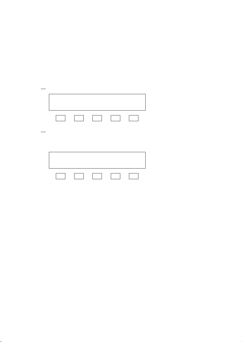
Fig.2-1 Items Contained in Package
RC04-PCR-LA Precautions and Preparation for Use 2-1

2.2 Handling Precautions
■ Never drop the remote controller or subject it to other
impact.
■ Do not place the remote controller where it could be
exposed to water or other liquid.
■ Do not use or store the remote controller in direct sunlight.
■ Do not use of store the remote controller in an area sus-
ceptible to rapid temperature changes.
■ When the remote controller is used with the provided magnet sheet, which attaches to the back of the remote controller, never place the remote controller near magneticsusceptible items, such as floppy disks and credit cards.
2.3 Combination with Other Options
The PCR-LA Series has various other options in addition to the
Remote Controller. Note that the following options cannot be used in
conjunction with the Remote Controller.
Table 2-1 Option That Cannot be Installed or Used
Together with the RC04-PCR-LA
Option name Model name
Remote Controller RC03-PCR-LA
Table 2-2 Option That Can be Installed Together with
the RC04-PCR-LA, but Cannot be Used
Simultaneously
Option name Model name
GPIB Interface IB03-PCR-LA
2-2 Precautions and Preparation for Use RC04-PCR-LA
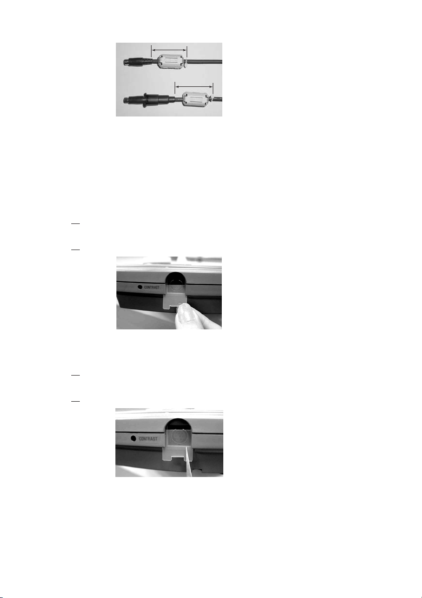
2.4 Connecting the Remote Controller Cable
CAUTION
NOTE
1. Connect the controller cable connector with a protection
2. Insert the protection cover, cover the connector and turn the
3. Connect the other connector of the remote cable to the TO
• Before connecting the controller cable, always turn
OFF the PCR-LA AC power supply POWER switch.
When removing the cable, first turn the POWER
switch of the PCR-LA power supply OFF.
• When turning ON the PCR-LA AC power supply POWER
switch, the PCR-LA AC power supply identifies the Remote
Controller that is connected. Therefore, before turning ON the
PCR-LA AC power supply POWER switch, connect the
Remote Controller to the PCR-LA AC power supply.
cover to one of the two connectors (see Fig. 2-2) in the
remote controller. Exercise care that the orientation of the
connector is correct.
cover clockwise to fix it securely.
REMOTE CONTROLLER connector on the front of the
PCR-LA power supply. In this case, align the cable connector such that it is oriented with that of the connector on the
front panel.
Fig.2-2 Connecting the Remote Controller Cable
2.5 Installation of the Split Cores
1. Unlock the core and open it.
2. Close the core so that the cable is not caught in it.
3. As shown in Fig. 2-3, tie up the cable with the accompanying stopper band. Keep the distance between the plug and
the core below 100 mm.
RC04-PCR-LA Precautions and Preparation for Use 2-3
Within 100 mm
Within 100 mm
Fig.2-3 Location of Split Core Installation
2.6 Installation of the Connector Cover
Install the connector cover of the 8P mini plug connector which is not
used.
Installation
1. As shown in Fig. 2-4, insert the accompanying connector
cover from the lower part of the connector.
2. Insert the cover till it is locked.
Fig.2-4 Connector Cover Installation
Removal
1. As shown in Fig. 2-5, unlock the connector cover with tweezers.
2. Slowly pulled down the connector cover.
Fig.2-5 Connector Cover Removal
2-4 Precautions and Preparation for Use RC04-PCR-LA
2.7 Moving Precautions
■ Before moving the PCR-LA AC power supply, always disconnect the controller cable.
Moving a PCR-LA AC power supply with this device connected may
place unreasonable stress on the remote controller cable or cause the
remote controller to fall.
■ When the magnet sheet is used, do not move a PCR-LA AC
power supply with the remote controller attached to the
side of the equipment.
Vibration during movement may cause the remote controller to fall.
■ When moving the equipment, follow the instructions given
in the PCR-LA AC Power Supply Operation Manual.
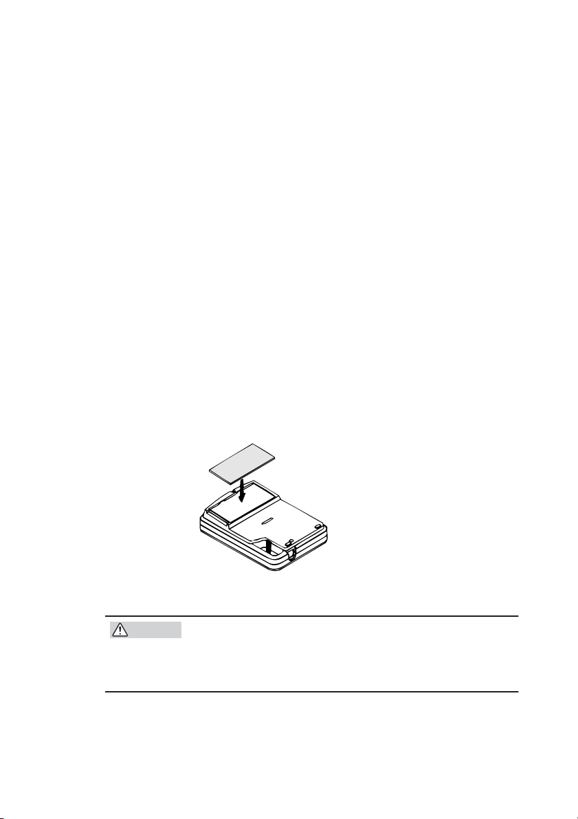
2.8 How to Use the Magnet Sheet
The Remote Controller has a magnet sheet that can be attached to the
back of the remote controller. This allows the remote controller to be
placed on the side panel of the PCR-LA AC power supply or other
steel surface.
Fig.2-6 Attaching the Magnet Sheet
CAUTION
RC04-PCR-LA Precautions and Preparation for Use 2-5
• When the provided magnet sheet is on the back of
the remote controller, never place the remote controller near magnetic-susceptible items, such as floppy
disks and credit cards.

2.9 Quick Reference Card
The remote controller has a quick reference card that briefly describes
keys and simulation waveforms. This card is useful when using the
memory, sequence, or special waveform output functions.
Fig.2-7 Quick Reference Card
2-6 Precautions and Preparation for Use RC04-PCR-LA

Chapter 3
Describes the operation check that must be conducted prior to operation of the Remote Controller.
After connecting the Remote Controller by the steps described in Chapter 2, check the Initial Setup Status and make an operation check.
Always make an operation check as described in this chapter, if you
have installed a new Remote Controller or changed its location, if the
operator changes, or if the Remote Controller has not been used for a
long time.
Before operating this device, read through the PCR-LA AC Power
Supply Operation Manual and gain an understanding of the basic
operations of the AC power supply.
Operation Check
3.1 Checking the Initial Setup Status
The condition in which a PCR-LA AC power supply and this device
are simultaneously purchased and power is fed for the first time (factory shipment status) is called Initial Setup Status. The following figure shows the remote controller LCD display under this condition.
5 0 . 0 0 H z 0 . 0 0 A 0 . 2 V
F RQ I r m s V r m s
The main setting in the Initial Setup Status are as follows:
• OUTPUT OFF
• RANGE 100 V
• AC/DC AC
• Frequency 50.00 Hz
• Voltage 0.0 V
• Voltage display mode RMS
• Current display mode RMS
If the Remote Controller is not in the Initial Setup Status, use the reset
function to activate the Initial Setup Status. Reset can be performed
either on the PCR-LA AC power supply or via the Remote Controller.
To perform a reset on the PCR-LA AC power supply, see instructions
RC04-PCR-LA Operation Check 3-1
in the PCR-LA AC Power Supply Operation Manual.
Note that performing a reset cancels all settings made thus far and
activates the Initial Setup Status.
Resetting Procedure Using the Remote Controller
1. Call the Home Position.
See the Home Position description given below.
2. Press the RESET (SHIFT, 6) key.
3. Verify that the ENTER LED blinks, activating ENTER wait
status.
4. Press the (SHIFT, ENTER) keys. This executes a reset.
DESCRIPTION
• Home Position
The status in effect immediately after the POWER switch is
turned ON is called the Home Position (regardless of OUTPUT ON/OFF). To return to the Home Position from another
mode, press the ESC key.
• ENTER Wait
This is the condition in which the ENTER key has not yet
been pressed to initiate the operations performed thus far. In
this condition, the ENTER LED on the Remote Controller
blinks.
To cancel a operation before pressing the ENTER key, press
the ESC key.
ENTER Wait for this device has the same meaning as the
ENT Wait of the PCR-LA AC power supplies.
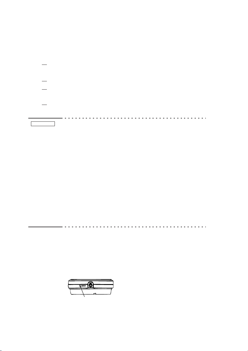
LCD (Liquid Crystal Display) Contrast Adjustment
To adjust the contrast of the Remote Controller LCD unit, use a small
screwdriver to turn the part shown in the figure. Adjust LCD contrast
to match lighting conditions at the operating location to obtain an
easy-to-see display.
CONTRAST
Fig.3-1 Contrast Adjustment
3-2 Operation Check RC04-PCR-LA
3.2 Operation Check
CAUTION
• Remote Controller operation must be checked after
the operation check of the PCR-LA AC power supply
has been completed.
Operation Check Procedure
The following describes how to make an operation check from the
Initial Setup Status.
1. Turn the PCR-LA AC power supply POWER switch ON.
The remote controller LCD displays the following Initial Setup
Status for a few seconds.
P C R 1 0 0 0 L A V e r 3 . 0 0
R C 0 4 - P C R - L A V e r 1 . 0 0
The upper part of the LCD displays the model and the ROM version
of the PCR-LA AC power supply connected, while the lower part
displays the model and ROM version of the Remote controller.
Regarding the appearance of any display other than the display
above, see the Note on the next page.
After a few seconds, the Home Position appears.
2. Press the F5 (Vrms) key to enter the voltage setting mode.
This changes the F5 Vrms indication to Vset.
5 0 . 0 0 H z 0 . 0 0 A 0 . 0 V
F RQ I r m s V s e t
F1 F2 F3 F4 F5
3. Turn JOG or SHUTTLE to check that the voltage changes
on the display.
This completes the operation check.
This operation check does not check all functions. However, if the
operation check has been complete, the main functions operate correctly.
RC04-PCR-LA Operation Check 3-3
NOTE
• When using the PCR-LA AC power supply with options
shown as follows, the Initial Setup Status display is different
by the option(s).
• Using the Single-phase Three-wire Driver (2P03-PCR-LA)
P C R - L A 2 P
R C 0 4 - P C R - L A V e r 1 . 0 0
• Using the Three-phase Driver (3P03-PCR-LA)
P C R - L A 3 P
R C 0 4 - P C R - L A V e r 1 . 0 0
• Using the Parallel-operation Driver (PD03M-PCR-LA and PD03S-
PCR-LA) and Single-phase Three-wire Driver (2P03-PCR-LA),
or the Single-phase/Single-phase Three-wire Output Terminal Kit
(OT01-PCR4000LA/2, OT01-PCR8000LA/2, or T01-PCR12000LA/2)
P C R - L A P D 2 P
R C 0 4 - P C R - L A V e r 1 . 0 0
• Using the Parallel-operation Driver (PD03M-PCR-LA and
PD03S-PCR-LA) and Three-phase Driver (3P03-PCR-LA),
or the Single-phase/Three-phase Output Terminal Kit (OT01PCR6000LA/3, OT01-PCR12000LA/3, or OT01-PCR18000LA/3)
P C R - L A P D 3 P
R C 0 4 - P C R - L A V e r 1 . 0 0
• If the following display or other messages appear, wait for
about ten seconds, then the display should change to the Initial Setup Status. In this condition, the PCR-LA AC power
supply back-up data has been lost for some reasons. Re-check
the steps described in sections 2.4 and 2.5. If this still does
not remedy the condition, notify Kikusui distributor/agent.
P A N E L B A C K U P L O S T
I N I T I A L S E T ! ! !
3-4 Operation Check RC04-PCR-LA

Chapter 4
Describes the operations of the Remote Controller and the extended
functions of the PCR-LA AC power supply.
Operation Method
4.1 Basic Operation of the Remote Controller
Remote controller operation is designed to be as much as possible the
same as that of the PCR-LA AC power supply control panel. However, part of the operation and operation of new functions provided by
the Remote Controller differ from that of the PCR-LA power supply
control panel.
The basic operating method of the Remote Controller is as follows:
1. To enter main function setting or execution status, press the
relevant key (MEM, SEQ, SIM, WAVE, or MODE).
Note that these keys are accepted only in the Home Position. For
information on how to use JOG and SHUTTLE, see “3.1.2 How
to Use JOG and SHUTTLE” in the PCR-LA AC Power Supply
Operation Manual.
2. After entering each function setting or execution status,
press the F1 to F5 function keys (located right below the
items displayed at the lower part of the display). The function keys correspond to the displayed items.
For example, in the following display (memory edit display), the
F1 key corresponds to “ADRS”, the F3 key to “FRQ”, and the F5
key to “Vrms”.
Note that there are slight deviations between the displayed letters
and key positions.
1 5 0 . 0 0 H z 0 . 0 V
A D R S F RQ V r m s
F1 F2 F3 F4 F5
In the figure below (next page example, sequence setting display),
the F1 to F5 keys correspond to the five items displayed at the
lower part of the display respectively.
RC04-PCR-LA Operation Method 4-1

0 5 0 . 0 0 H z 0 . 0 V
A D R S R F R Q R V a c
F1 F2 F3 F4 F5
• If there are several operation displays, the MENU LED lights.
Press the MENU key to access the next display. Press the
(SHIFT, MENU) keys to return to the previous display.
• To exit the current status, press the ESC key.
• Blinking of the ENTER LED during operation means that the
ENTER wait status is activated.
• In the ENTER wait status, operation input thus far is not initiated until the ENTER key is pressed. Pressing the ESC key cancels the ENTER Wait status.
4.2 Functions in Common with the PCR-LA AC Power Supply
This section discusses the functions common to the Remote Controller
and the PCR-LA AC power supply control panel. The functions are
separated into those that can be accomplished in the same way as on the
PCR-LA AC power supply and those requiring different key operation.
4.2.1 Functions Whose Key Operation is the Same as That of the PCR-LA AC Power Supply
The following functions are the same key operation as that of the
PCR-LA AC power supply control panel. For details about operation,
refer to the PCR-LA AC Power Supply Operation Manual.
Table 4-1 Functions Whose Key Operation is the Same as
That of the PCR-LA AC Power Supply
Functions Key operation
OUTPUT ON/OFF OUTPUT key
Self-test function SELF TEST (SHIFT, 3)
Key-lock function KEYLOCK (SHIFT, 4)
Sensing function SENSING (SHIFT, 5)
Reset function RESET (SHIFT, 6)
Output voltage range change RANGE (SHIFT, 7)
Synchronization function SYNC (SHIFT, 9)
4-2 Operation Method RC04-PCR-LA

4.2.2 Functions Whose Key Operation Differs from That of the PCR-LA AC Power Supply
Some functions available on the PCR-LA AC power supply control
panel require slightly different key operation on the Remote Controller because of the device’s key arrangement.
Table 4-2 Functions Whose Key Operation Differs from
That of the PCR-LA AC Power Supply
Functions
Voltage setting function V key
Frequency setting function F key F1 (FRQ) key
Limit value setting function V key F5 (Vmax/Vmin) key
Voltage display mode
change
Current display mode
change
The meaning of the abbreviations Vrms, Vpk, Vset, etc, are as follows:
Vrms = rms voltage Fmax = maximum frequency
Vpk = peak voltage Fmin = minimum frequency
Vset = set voltage Imax = maximum current
Vave = average voltage Irms = rms current
FRQ = frequency Ip = peak current
Vmax = maximum voltage Iph = peak holding current
Vmin = minimum voltage WATT = power
For an explanation of set values, rms, peak values, and average values, see the Description “Voltage Display Mode” in “8.7 Voltage Display Modes and Measurement Methods” of the PCR-LA AC Power
Supply Operation Manual.
PCR-LA AC
Power Supply
F key F1 (Fmax/Fmin) key
I key F3 (Imax) key
(SHIFT, V) key Vrms/Vpk/Vset/Vave (SHIFT, F5)
(SHIFT, I) key Irms/Ip/Iph/WATT/Iave (SHIFT, F3)
Remote Controller
F5 (Vrms/Vpk/Vset/Vave) key
key
key
Iave = average current
Voltage setting function
To enter the voltage setting mode on the Remote Controller, press the
F5 (Vrms/Vpk/Vset/Vave) key in the Home Position. (On the PCRLA AC power supply, press the V key.)
RC04-PCR-LA Operation Method 4-3

Frequency setting function
To enter the frequency setting mode on the Remote Controller, press
the F1 (FRQ) key in the Home Position. (On the PCR-LA AC power
supply, press the F key.)
Limit value setting function
To enter the voltage, frequency, or current limit value setting mode on
the Remote Controller, press the LIMIT (SHIFT, 1) key in the Home
Position status to enter the limit value display mode, and then press
the F5 (Vmax/Vmin), F1 (Fmax/Fmin), or F3 (Imax) key. (On the
PCR-LA AC power supply, press the LIMIT (SHIFT, 1) key to enter
the limit value display mode, then press the V, F, or I key.)
This function is valid only in AC or DC mode.
Voltage display mode change
To switch the voltage display mode on the Remote Controller, press
the Vrms/Vpk/Vset/Vave (SHIFT, F5) key. (On the PCR-LA AC
power supply, press the (SHIFT, V) keys.)
Current display mode change
To switch the current display mode on the Remote Controller, press
the Irms/Ip/Iph/WATT/Iave (SHIFT, F3) key. (On the PCR-LA AC
power supply, press the (SHIFT, I) keys.)
The PCR-LA AC power supply control panel has no “Iph” display
mode. This function is added by the Remote Controller. For details,
see “4.3.4 Peak Holding Current Measurement Mode”.
4.3 Functions Extended by Using the Remote Controller
The Remote Controller extends some of the PCR-LA AC power supply functions. This section describes the extended functions and how
to use them.
4.3.1 AC + DC Mode
The PCR-LA AC power supplies allow three output voltage modes,
AC, AC-S and DC. Use of the Remote Controller allows an additional
output voltage mode, AC + DC mode. The AC + DC mode is a function that superimposes DC voltage on AC voltage or vice versa.
4-4 Operation Method RC04-PCR-LA
Output Voltage Mode Change Procedure
1. Press the OUTPUT key to turn output OFF.
2. Press the ESC key to call the Home Position.
The following display shows the Home Position in the Initial
Setup Status. The display differs depending on the content stored.
5 0 . 0 0 H z 0 . 0 1 A 0 . 2 V
F RQ I r m s V r m s
3. Press the AC/DC (SHIFT, 8) key to activate the ENTER Wait
status.
Each time the AC/DC (SHIFT, 8) key is pressed, the AC, AC-S,
DC, or AC + DC output voltage mode will be selected and confirmed as shown below.
AC DC AC+DCAC-S
In the AC + DC mode, the AC + DC voltage peak value can be set in
the DC voltage setting range.
AC + DC
voltage peak value
0 V
Fig.4-1 AC + DC Voltage Peak Value
• In the AC + DC mode, the voltage and frequency limit values
respectively set in the AC or DC modes are valid. The AC + DC
mode does not allow current limit change.
Output Voltage Setting Procedure
1. Press the ESC key to call the Home Position.
2. Press the F5 key to activate the voltage setting mode.
Each time the F5 key is pressed, the AC voltage setting mode and
DC voltage setting mode change alternately.
In the AC voltage setting mode, “AC” blinks in the MODE display
area of the device; in the DC voltage setting mode, “DC” blinks in
the MODE display area. Use the numeric keys or JOG/SHUTTLE
to set the AC or DC output voltage. For setting using the numeric
keys, press the ENTER key to confirm the value.
RC04-PCR-LA Operation Method 4-5

4.3.2 Memory Function
The PCR-LA AC power supplies have the memory function that
stores nine sets of voltage and frequency settings in memory
addresses up to 9 and allows them to be read for output whenever
necessary. Connecting the Remote Controller to a PCR-LA AC power
supply allows the number of set values stored in the memory (memory addresses) to be extended to 99.
The Remote Controller also offers memory operation in the AC + DC
mode, allowing simultaneous output of AC and DC voltages stored in
the same memory address. For memory addresses 1 to 9, setting is
common to both the PCR-LA AC power supply and the Remote Controller.
The procedure to store data in the memory is as follows:
Memory Setting Procedure
Memory setting is available only in the Home Position.
1. Press the ESC key to call the Home Position.
2. Press the M-EDIT (SHIFT, MEN) key to enter the memory
edit mode.
1 5 0 . 0 0 H z 0 . 0 V
A D R S F RQ V r m s
F1 F2 F3 F4 F5
3. Using the F1, F3, and F5 function keys and the MENU key,
select the desired item.
Selectable items are shown in Table 4-3. To select an item, follow
steps 4 onward.
The Setting display consists of two displays that can be switched
using the MENU key.
4-6 Operation Method RC04-PCR-LA
Table 4-3 Items That Can be Set
Display Key Setting items Mode available
First
display
Second
display
F1 (ADRS) Memory address (step 4)
F3 (FRQ) Frequency (step 4) AC or AC + DC mode
F5 (Vrms) AC voltage (step 4) AC or AC + DC mode
MENU, then F1
(ADRS)
MENU, then F3
(WAVE)
MENU, then F5
(Vdc)
Memory address
Waveform bank (step 5) AC or AC + DC mode
DC voltage (step 5) DC or AC + DC mode
4. The cursor blinks at “1” of ADRS. Enter the desired address
and press the ENTER key to confirm it.
1 5 0 . 0 0 H z 0 . 0 V
A D R S F RQ V r m s
F1 F2 F3 F4 F5
Next, press the F3 key to set frequency or the F5 key to set AC
voltage. The cursor moves to “FRQ” or “Vrms”. Set the value you
wish to store in the memory using the numeric keys or JOG/
SHUTTLE.
5. To set waveform bank or DC voltage, press the MENU key
to call the following display, then set waveform bank (F3) or
DC voltage (F5).
For the waveform banks, see “4.3.8 Special Waveform Output”.
1 W0 0 + 0 . 0 V
A D R S WA V E V d c
F1 F2 F3 F4 F5
6. Press the ESC key to quit the memory edit mode.
RC04-PCR-LA Operation Method 4-7
NOTE
• Note that when voltage data is read from the memory in the
AC + DC mode for output, output voltage changes as follows:
An AC voltage set value (Vrms) and DC voltage set value
(Vdc) are independently stored in the memory. When they are
read, the AC voltage value (Vrms) is output slightly faster
(approximately 30 μs) than the DC voltage value (Vdc).
Therefore, output voltage changes as follows:
Example ADRS 1: Vrms = 0V, Vdc = +100V
ADRS 2: Vrms = 100V, Vdc = 0V
ADRS 3: Vrms = 0V, Vdc = +100V
Vrms (ADRS2) + Vdc (ADRS1)
Vrms (ADRS1)
(241 V)-
(100 V)-
+ Vdc (ADRS1)
0 V-
Vrms (ADRS2)
+ Vdc (ADRS2)
30 μs 30 μs
Vrms (ADRS3) + Vdc (ADRS2)
Vrms (ADRS3)
+ Vdc (ADRS3)
ADRS3ADRS2ADRS1
Fig.4-2 Changes in the Output Voltage in Reading
Data from Memory
In the actual case, the duration of 30 μs shown in the above
figure is very short in comparison with each ADRS time. Output voltage changes like pulse.
4-8 Operation Method RC04-PCR-LA

Memory Read Procedure
Select the same output voltage mode (AC, DC, or AC + DC) as used
for setting of the memory.
To read data set in each address (“ADRS”), take the following steps.
1. Press the ESC key to call the Home Position.
2. Press the MEM key to display the memory content.
1 5 0 . 0 0 H z 0 . 0 V
A D R S F RQ V r m s
(Example of Initial Setup Status)
(First display)
3. Press the numeric keys or use JOG/SHUTTLE to enter a
memory address.
This will cause the set values stored in the entered memory
address to be read out. The set values to be read differ depending
on the output voltage mode. For more information, see Table 4-3.
2 1 0 0 . 0 H z 1 0 0 V
A D R S F RQ V r m s
(Example of the display showing that FRQ = 100 Hz and Vrms = 100 V
are set in ADRS2)
(First display)
To display waveform bank and DC voltage set in the same
address, press the MENU key.
2 W0 0 + 0 . 0 V
A D R S WA V E V d c
(Example of the display showing that waveform bank W00 and DC voltage +0 V
are set in ADRS2)
(Second display)
4. To confirm the read set values, press the ENTER key. To
cancel them, press the ESC key.
Pressing the ESC key allows you to exit the memory content-indicating display. Press the ENTER key to confirm the set values,
then press the ESC key to end the memory read operation.
RC04-PCR-LA Operation Method 4-9
4.3.3 Power, Power Factor, and Apparent Power Measurement Mode
The PCR-LA AC power supplies have a power display function.
However, using the Remote Controller allows simultaneous display
of power, power factor, and apparent power (VA).
Procedure for Switching to Power, Power Factor, and Apparent Power Display
1. Press the ESC key to call the Home Position.
5 0 . 0 0 H z 0 . 0 1 A 0 . 2 V
F RQ I r m s V r m s
F1 F2 F3 F4 F5
2. Press the MENU key.
This causes the power (WATT), apparent power (VA) and power
factor (PF) display to appear.
0 . 0 W 0 . 0 0 V A 0 . 0 0
WA T T V . A P . F
F1 F2 F3 F4 F5
Press the MENU key again, or press the ESC key to call the Home
Position.
4.3.4 Peak Holding Current Measurement Mode
The PCR-LA AC power supplies have the peak current display function. However, using the Remote Controller allows peak holding current display in addition to peak current display. The difference
between peak value and peak holding value measurements is as follows:
Peak Value Measurement
In peak value measurement, the peak value is cleared for every measurement cycle. The Remote Controller’s peak value measurement
measures the current peak using the analog peak holding circuit and
obtains the maximum absolute value of that data. Therefore, peak current display shows an absolute value (no positive or negative symbol).
A peak value can be measured in the AC, DC, or AC + DC mode.
4-10 Operation Method RC04-PCR-LA
 Loading...