

Kikusui PWX750MLF, PWX750LF, PWX750MHF, PWX1500ML, PWX750HF User Manual
...
User’s Manual
Regulated DC Power Supply
PWX Series
750W model
PWX750LF
PWX750MLF
PWX750MHF
PWX750HF
1500W model
PWX1500L
PWX1500ML
PWX1500MH
PWX1500H
PART NO.IB031041
Sep. 2016
Search by Topic 7
Component Names 8
Installation and Preparation 11
Connecting the Power Cord 12
Turning the Power On 15
Rack Mounting 16
Load Considerations 17
Load Cables 19
Connecting to the Output Terminals 20
Sensing 23
Basic Functions 27
Measured Value Display and Setting Display
28
Panel Operations 29
Output Operations 30
Operation Overview 31
CV Power Supply and CC Power Supply 33
Using the PWX series as a CV or CC
Power Supply 35
Protection Functions and Alarms 36
CONFIG Settings 42
Preset Memory Function 55
Locking Panel Operations (Key lock) 57
Bleeder On/Off Feature 57
Switching from Remote Mode to Local
Mode 59
Factory Default Settings (Initialization) 59
External Control 61
Overview 62
About the J1 Connector 62
Output Terminal Insulation 64
Controlling the Output Voltage 67
Controlling the Output Current 69
Controlling the Output On and Off States 71
Controlling Output Shutdown 73
Controlling the Clearing of Alarms 74
External Monitoring 75
Parallel/Series Operation 77
Master-Slave Parallel Operation 78
Series Operation 84
Maintenance 89
Calibration 90
Specifications 93
750W model 95
1500W model 104
Factory Option 113
Isolated Analog Interface 114
Variable Internal Resistance Feature 118
Appendix121

These manuals are intended for users of the Regulated DC
About the PWX series Manuals
Checking the Package Contents
Power Supply and their instructors. It is assumed that the
reader has knowledge about electrical aspects of regulated
DC power supplies.
Documentation Structure
Copyrights
The contents of this manual may not be reproduced, in whole
or in part, without the prior consent of the copyright holder.
The specifications of this product and the contents of this manual are subject to change without prior notice.
© 2011 Kikusui Electronics Corporation
Safety information
This document contains general safety precautions for this
product. Keep them in mind and make sure to observe
them.
User’s manual (this manual, PDF)
This manual is intended for first-time users of this product. It
provides an overview of the product and notes on usage. It
also explains how to configure the product, operate the
product, perform maintenance on the product, specifications
the product, and so on. To effectively use the product features, read this manual from beginning to end.
We recommend that you read it thoroughly before using this
product for the first time.
If you forget how to use the product or if a problem occurs,
we recommend that you refer to this manual again.
Quick reference
This manual explains Panel description and operation
briefly.
Communication Interface Manual (HTML,
partially PDF)
This manual contains details about using commands to control the product remotely. It also contains details about the
multichannel function (Virtual Multi Channel Bus), which
makes it possible to control up to 31 PWXs from a single
PC.
The interface manual is written for readers with sufficient
basic knowledge of how to control power supplies using a
PC.
The command list is provided in PDF format.
PDF and HTML files are included in the accompanying CDROM. Adobe Reader is required to view the PDF files.
Microsoft Internet Explorer or Google Chrome is required to
view the HTML files.
When you receive the product, check that all accessories are
included and that the accessories have not been damaged
during transportation.
If any of the accessories are damaged or missing, contact
your Kikusui agent or distributor.
We recommend that you save all packing materials, in case
the product needs to be transported at a later date.
Part name 750 W model 1500 W model
Power cord 1 pc.
OUTPUT terminal cover 1 set 1 set
INPUT terminal cover set
Output terminal bolt set
PWX750LF
PWX750MLF
PWX1500L
PWX1500ML
PWX750MHF
PWX750HF
PWX1500MH
PWX1500H
Chassis connection wire 1 pc. 1 pc.
J1 connector plug kit 1 set 1 set
Packing list 1 pc. 1 pc.
Quick reference English: 1 pc.
Safety information 1 copy 1 copy
CD-ROM 1 disc 1 disc
─
M8 bolts: 2 sets M8 bolts: 2 sets
M5 bolts: 2 sets M5 bolts: 2 sets
Japanese: 1 pc.
─
1 set
English: 1 pc.
Japanese: 1 pc.
Firmware versions that this manual covers
This manual covers firmware versions 3.0X.
When contacting us about the product, please provide us with:
The model (marked in the top section of the front panel)
The firmware version (see page 15)
The serial number (marked on the rear panel)
Trademarks
Microsoft, Internet Explorer, and Windows are either registered trademarks or trademarks of Microsoft Corporation in the
United States and/or other countries.
Other company names and product names used in this manual are generally trademarks or registered trademarks of the
respective companies.
2 PWX

The PWX Series is a constant voltage (CV)/constant current
Product Overview
(CC) automatic crossover power supply that can output a wide
range of voltage and current within rated output power.
It can be controlled remotely through the standard-equipped
communication feature.
Power Model Maximum oper-
750 W
model
1500 W
model
PWX750LF 75 A 0 V to 30 V
PWX750MLF 28 A 0 V to 80 V
PWX750MHF 10 A 0 V to 230 V
PWX750HF 3.5 A 0 V to 650 V
PWX1500L 150 A 0 V to 30 V
PWX1500ML 56 A 0 V to 80 V
PWX1500MH 20 A 0 V to 230 V
PWX1500H 7 A 0 V to 650 V
ating current
Operating voltage
Features
Communication feature
RS232C, USB, and LAN interfaces are all installed as standard.
The remote interfaces comply with IEEE Std 488.2 1992
and SCPI Specification 1999.0. Because the LAN interface
complies with the LXI standard, the construction of a highly
cost-effective system is possible. If you use the multichannel (VMCB) function, you can construct a multichannel
power supply system in which up to 31 PWXs are controlled
from a single PC.
Master-slave parallel operation
You can increase the PWX series output current by connecting up to four units in parallel. You can set one unit as
the master unit, and control the remaining units as slave
units.
Setting preset feature
You can save up to three sets of output settings (the combination of the voltage value and current value). You can simply select a set of output settings that you want to use rather
than having to specify each setting every time.
Automatic output on setting
You can set the PWX series so that when a protection function is activated and the output is turned off, output is automatically turned back on when the problem that caused the
protection function to be activated is fixed.
Set voltage/current limitation feature
You can apply limits to the voltage and current settings.
This prevents you from setting an appropriate value by mistake, which would cause the output to turn off.
Overcurrent protection (OCP) detection time setting
You can set a detection time, which is the amount of time
that an overcurrent must persist after the first detection of
the overcurrent before the overcurrent protection (OCP) is
activated. By setting the detection time, you can prevent an
alarm from occurring when an inrush current from the EUT
connected to the output causes an excessive current to flow
temporarily.
Bleeder on/off feature
You can turn the bleeder circuit on and off. Turn the bleeder
circuit off when you do not want the internal bleeder circuit
to sink output current. When you connect a battery, you can
prevent excessive electrical discharges by turning the
bleeder circuit off.
Compatibility with other products
You can set the command language and emulation that are
used during remote control. By setting the command language, you can enable the PWX to support the proprietary
commands of other products. By selecting the emulation,
you can remotely control products other than the PWX.
Isolated analog interface (factory option)
You can use isolated optical signals to set and monitor the
output voltage and current. The signal is isolated from the
reference potential of this product.
You can use a voltage control (0 V to 5 V or 0 V to 10 V) or
a current control (4 mA to 20 mA).
Variable internal resistance feature (Factory option)
The internal resistance of rechargeable batteries, solar batteries, fuel cells, and the like can easily be simulated. By
setting the internal resistance value in constant voltage (CV)
mode, you can decrease the output voltage according to the
output current.
PWX 3

When using this product, be sure to observe the “Safety
Safety Precautions
Precautions Concerning
Installation Location
Notations Used in This Manual
WARNING
DESCRIPTION
Memo
Precautions” in the Safety information manual.
When installing this product, be sure to observe the
“Precautions Concerning Installation Location” in the
Safety information manual. The following precautions
pertain only to this product.
• When installing this product, be sure to observe the temperature and humidity ranges indicated below.
Operating temperature range: 0 °C to +50 °C
(32 °F to 122 °F)
Operating humidity range: 20 %rh to 85 %rh
(no condensation)
• When storing this product, be sure to observe the temperature and humidity ranges indicated below.
Storage temperature range: -10 °C to +60 °C
(14 °F to 140 °F)
Storage humidity range: 90 %rh or less (no condensation)
• In this manual, the PWX Series Regulated DC Power Supply is referred to as the “PWX Series” or “PWX.”
• The term “PC” is used to refer generally to both personal
computers and workstations.
• The screen captures used in this manual may differ from the
actual screens that appear on the PWX series. The screen
captures are merely examples.
• The following markings are used in this manual.
Indicates a potentially hazardous situation which, if
ignored, could result in death or serious injury.
CAUTION
Indicates a potentially hazardous situation which, if
ignored, may result in damage to the product or other
property.
Indicates information that you should know.
Explanation of terminology or operation principle.
See
Indicates a reference to detailed information.
Indicates reference to detailed information operation manual.
CFxx:x
“CF” stands for a CONFIG parameter. The two digits after
CF indicate the CONFIG parameter number. The value
after the colon indicates the selected setting.
SHIFT+key name (blue characters below the keys)
Indicates an operation that requires you to press a key
indicated in blue characters (below the key) while holding
down the SHIFT key.
Indicates useful information.
4 PWX

Contents
About the PWX series Manuals ..................2
Checking the Package Contents ................2
Product Overview .......................................3
Safety Precautions ......................................4
Precautions Concerning Installation Location
4
Notations Used in This Manual ...................4
Search by Topic ...........................................7
Component Names......................................8
Installation and Preparation
1
Connecting the Power Cord............................. 12
Turning the Power On...................................... 15
Rack Mounting ................................................. 16
Load Considerations ........................................ 17
Load Cables..................................................... 19
Connecting to the Output Terminals ................ 20
Sensing ............................................................ 23
Basic Functions
2
Measured Value Display and Setting Display .. 28
Panel Operations ............................................. 29
Output Operations............................................ 30
Operation Overview ......................................... 31
CV Power Supply and CC Power Supply ........ 33
Using the PWX series as a CV or CC Power Sup-
ply ....................................................................
Protection Functions and Alarms ..................... 36
CONFIG Settings ............................................. 42
Preset Memory Function.................................. 55
Locking Panel Operations (Key lock) ............... 57
Bleeder On/Off Feature.................................... 57
Switching from Remote Mode to Local Mode .. 59
Factory Default Settings (Initialization) ............ 59
750 W model ............................................. 12
1500 W model ........................................... 13
Turning the POWER switch on ................. 15
Turning the POWER switch Off................. 16
Local sensing ............................................ 24
Remote sensing ........................................ 24
35
Alarm occurrence and clearing alarms...... 36
Protection function activation .................... 37
CONFIG parameter details ....................... 45
Saving settings to preset memory............. 55
Recalling preset memory entries............... 56
3
4
5
6
7
External Control
Overview.......................................................... 62
About the J1 Connector................................... 62
Output Terminal Insulation............................... 64
When the output terminal is not grounded
(floating)....................................................
When the output terminal is grounded ...... 65
Cautions when using the external voltage
(Vext) ........................................................ 66
Controlling the Output Voltage......................... 67
Control using an external voltage (Vext)... 67
Control using an external resistance (Rext)68
Controlling the Output Current......................... 69
Control using an external voltage (Vext)... 69
Control using an external resistance (Rext)70
Controlling the Output On and Off States ........ 71
Controlling Output Shutdown........................... 73
Controlling the Clearing of Alarms ................... 74
External Monitoring.......................................... 75
64
Parallel/Series Operation
Master-Slave Parallel Operation...................... 78
Features of the PWX series during master-
slave parallel operation.............................
Connection (master-slave parallel operation) .
80
Settings (master-slave parallel operation) 82
Starting master-slave parallel operation .. 83
Series Operation.............................................. 84
Features of the PWX series during series op-
eration.......................................................
Connection (series operation)................... 86
Settings (series operation)........................ 87
Starting series operation........................... 87
78
84
Maintenance
Calibration........................................................ 90
Calibration overview.................................. 90
Calibration procedure................................ 91
Specifications
750W model..................................................... 95
1500W model................................................. 104
Factory Option
Isolated Analog Interface ............................... 114
Isolated Analog Interface Connector....... 115
Setup and Operation............................... 116
Specifications.......................................... 11 7
PWX 5

Variable Internal Resistance Feature 118
Setting 118
Variable range 119
Specifications 119
Appendix
A Options ......................................122
B Troubleshooting124
6 PWX
Search by Topic
Troubleshooting
See “Troubleshooting” on page 124.
• I want to check the accessories. →See “Checking the Package Contents”
or the included packing list.
p.2
• The installation space is limited, so I want
to check the installation conditions.
→
See the included “Safety Precautions”
document, or the electronic version of
the document on the CD-ROM.
–
• How do I connect the AC power supply?→“Connecting the Power Cord” p.12
• What kind of load cables should I use?
→
“Load Cables” p.19
• How do I ensure stable voltage when the
cables connected to the load are long (the
distance to the load is long)?
→
“Sensing”
p.23
• How do I rack mount the PWX series?
What kind of parts are needed?
→
“Rack Mounting”
p.16
• How do I use remote sensing to stabilize
the PWX series?
→“Sensing”
p.23
• How do I set the protection functions to
prevent damage to the load?
→“Protection Functions and Alarms”
p.36
• After a protection function has been acti-
vated, how do I restart tests automatically
when the cause of the alarm is fixed?
→“Alarm occurrence and clearing alarms”
p.36
• How do I set the communication condi-
tions for remote control?
→See the Communication Interface Man-
ual on the CD-ROM.
–
• How do I check the settings in preset
memory?
→“Recalling preset memory entries”
p.56
• How do I reset the PWX series to its fac-
tory default settings?
→“Factory Default Settings (Initialization)”
p.59
• How do I use the multichannel (VMCB)
function to construct a multichannel power
supply system?
→See the Communication Interface Man-
ual on the CD-ROM. –
• How do I use the PWX series as a con-
stant voltage power supply (CV mode)?
→“Using the PWX series as a CV or CC
Power Supply”
p.35
• How do I use the PWX series as a con-
stant current power supply (CC mode)?
• How do I operate the PWX series at a
specific current? How do I save current
values to the preset memory?
→“Preset Memory Function”
p.55
• How do I control the output voltage with
an external DC voltage?
→“Overview”
p.62
• How do I monitor the output voltage and
output current?
→“External Monitoring”
p.75
• How do I use parallel operation to
increase the current capacity?
→“Master-Slave Parallel Operation”
p.78
• How do I prevent the settings from being
changed?
→
“Locking Panel Operations (Key lock)”
p.57
• How do I clean the PWX series? →See the included “Safety Precautions”
document, or the electronic version of
the document on the CD-ROM.
–
• How do I calibrate the PWX series? →“Calibration” p.90
Preparation
Setup
Operation
Maintenance
PWX 7
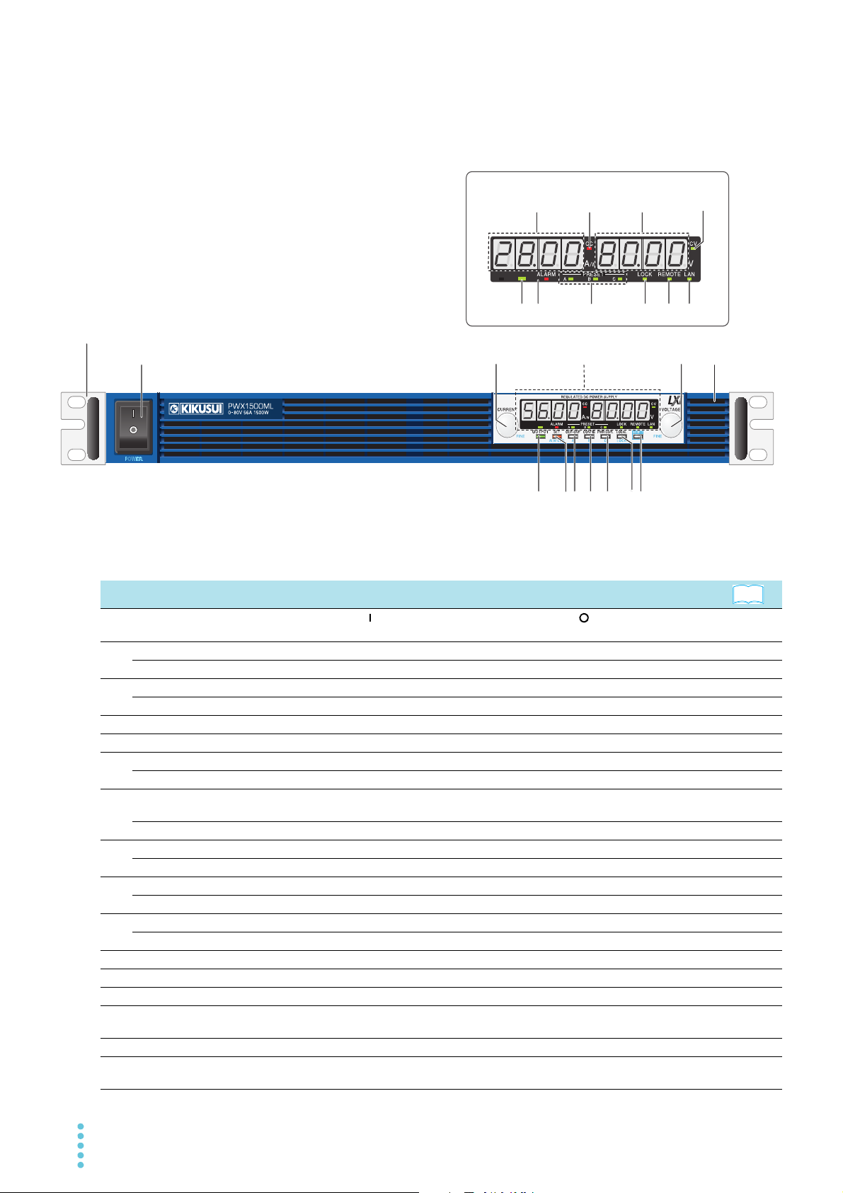
Component Names
16 17 18 19 20 21
15
1312 14
5 67 8 9 10 11
23
4
1
Display area
Rack mount bracket
Display area
See
Front Panel
No.
Name Function
1 POWER switch
CURRENT knob Used to set the current value or select a parameter number in the CONFIG settings. p.29, p.42
2
FINE Used to make fine current value adjustments. p.29
VOLTAGE knob Used to set the voltage value or change the value of a CONFIG parameter. p.29, p.42
3
FINE Used to make fine voltage value adjustments. p.29
4 Air inlet (louver) Air inlet for cooling the inside of the PWX series. –
5 OUTPUT key Used to turn output on and off. p.30
SET key Used to set and confirm the output voltage and output current (the key has an LED). p.28
6
ALM CLR key Used to release protection functions that have been activated (the key has an LED). p.37
• OVP keys
OCP
7
A Used to recall and save the value of preset memory A (the key has an LED). p.55
CONFIG key Used to configure the various operating conditions (the key has an LED). p.42
8
B Used to recall and save the value of preset memory B (the key has an LED). p.55
PWR DSPL key Used to display the output power on the ammeter (the key has an LED). p.28
9
C Used to recall and save the value of preset memory C (the key has an LED). p.55
LOCAL key Used to switch between local mode and remote mode (the key has an LED). p.59
10
LOCK key Used to lock the operation of all keys other than the OUTPUT key (the key has an LED). p.57
11 SHIFT key Used to enable the functions that are written in blue characters below the key. –
12 Ammeter Displays the current, power, or the parameter number of a CONFIG parameter. p.28, p.42
13 CC LED Lights in red during constant current mode. p.35
14 Voltmeter Displays the voltage, the value of a CONFIG parameter, or the cause of an alarm.
15 CV LED Lights in green during constant voltage mode. p.35
16 OUTPUT LED
Flip the switch to the ( ) side to turn the power on. Flip it to the ( ) side to turn the power
off.
Used to set and display the overcurrent protection (OCP), overvoltage protection (OVP),
undervoltage limit (UVL) trip points (the key has an LED).
Lights in green when output is turned on. Blinks orange when output is on and a protection
function has been activated.
p.15
p.38
p.28, p.36,
p.42
p.30, p.36
8 PWX

No.
See
634
7
8 9
10
2 5
Example of PWX1500L
Example of PWX750LF
1
634
7
8 9
10
2
5
1
See
Name Function
17 ALARM LED
18 PRESET LED
19 LOCK LED Lights in green when the keys are locked. p.57
20 REMOTE LED Lights in green during remote control. –
21 LAN LED
Lights in red when a protection function has been activated, However, does not light when
a undervoltage limit (UVL) protection has been activated, Blinks red when the power limit
(POWER LIMIT) has been activated.
A: Lights in green when the memory A values are being recalled or saved.
B: Lights in green when the memory B values are being recalled or saved.
C: Lights in green when the memory C values are being recalled or saved.
Lights and blinks when the LAN interface is in use.
• No fault status: Lights in green.
• Fault status: Lights in red.
• Standby status: Lights in orange.
• WEB identify status: Blinks green.
p.36
p.55
Rear Panel
–
No.
Name Function
1 DC OUTPUT Output connector p.20
2 USB USB port for controlling the PWX series remotely
3 RS232C RS232C port for controlling the PWX series remotely
4 LAN Ethernet port for controlling the PWX series remotely
5 Air outlet Air outlet for cooling the inside of the PWX series –
6AC INPUT
7 Chassis terminal Connector for grounding the output –
Sensing terminal connec-
8
tors
9 J1 External control connector p.62, p.77
10 Option slot Slot for the isolated analog interface option (factory option)
PWX 9
On the 750 W model, this is the AC inlet.
On the 1500 W model, this is the AC input terminal.
Terminals to connect the sensing cables p.23
Interface
Manual
p.12, p.13
p.114

This page is intentionally blank.
10 PWX

Installation and Preparation
This chapter describes how to turn on the
PWX series, what kind of load cables to
use, and how to connect cables to the output connectors.
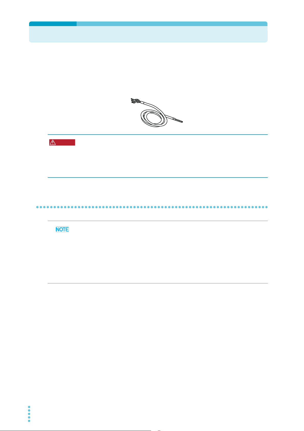
Connecting the Power Cord
AC5.5-3P3M-M4C-VCTF
For the 1500 W model
WARNING
This product is a piece of equipment that conforms to IEC Overvoltage Category II (equipment that consumes energy supplied from a fixed installation).
A power cord is not included with this 1500 W model. Use a power cord that conforms to this
product’s rated AC input voltage and current.
The following specialized power cords are available as options (CE non-compliant).
Risk of electric shock.
• This product is a piece of equipment that conforms to IEC Safety Class I (equipment
that has a protective conductor terminal). Be sure to earth ground the product to
prevent electric shock.
• The product is grounded through the power cord ground wire. Connect the protective conductor terminal to earth ground.
750 W model
• Use the supplied power cord to connect to the AC line.
• The power cord with a plug can be used to disconnect the PWX series from the AC power
• Do not use the specialized power cord with other instruments.
1
2
3
If the supplied power cord cannot be used because the rated voltage or the plug shape is
incompatible, have a qualified engineer replace it with an appropriate power cord that is 3
m or less in length. If obtaining a power cord is difficult, contact your Kikusui agent or distributor.
line in an emergency. Connect the plug to an easily accessible power outlet so that the plug
can be removed from the outlet at any time. Be sure to provide adequate clearance around
the power outlet.
Check that the AC power line meets the nominal input rating of the product.
The product can receive a nominal line voltage in the range of 100 Vac to 240 Vac at
50 Hz or 60 Hz.
Check that the POWER switch is turned off.
Connect the power cord to the AC inlet on the rear panel.
Insert the power plug into a grounded outlet.
4
12 PWX
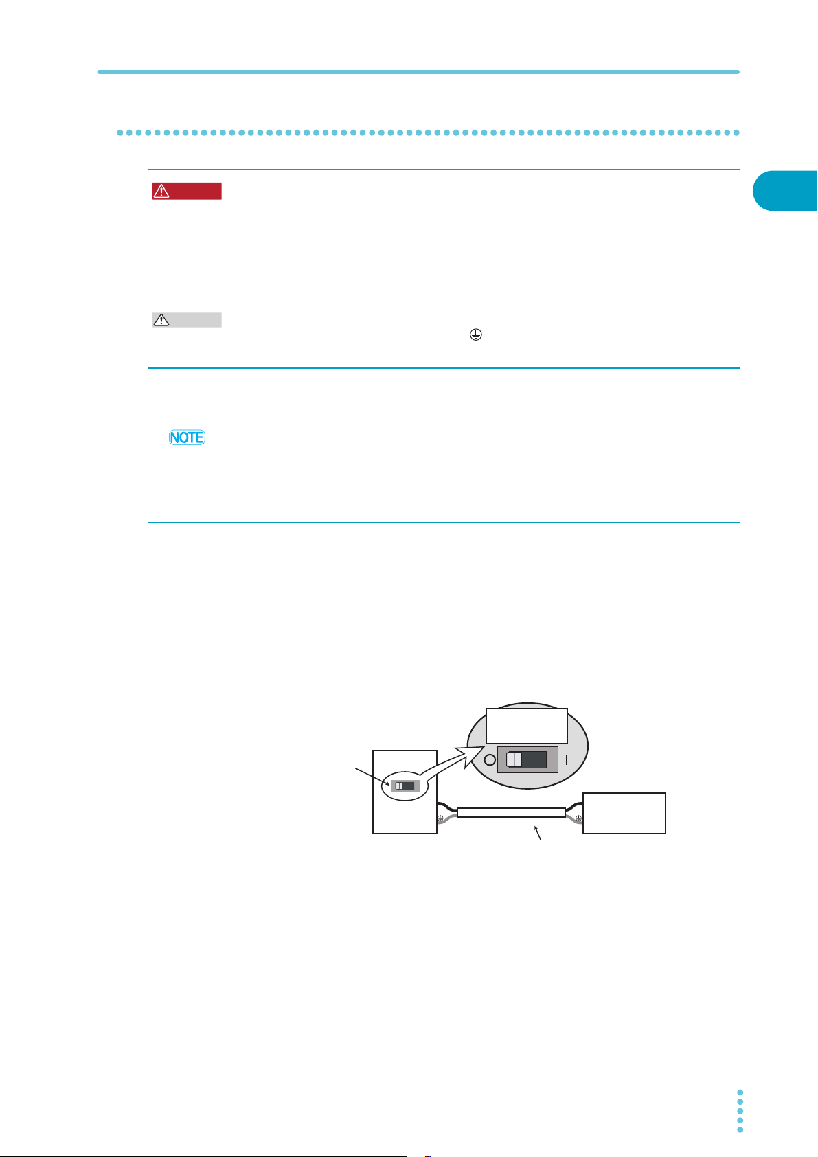
1500 W model
WARNING
CAUTION
PWX1500ML
Switchboard
N
L
N
L
Breaker indication example
For the
PWX1500ML only
Power cord
PWX1500ML
dedicated breaker
Connecting the Power Cord
Risk of electric shock.
• Before you connect the power cord, turn off the switchboard breaker (a switch that
cuts off the power supply from the switchboard).
Risk of fire.
• Be sure to have a qualified engineer make the connection to the switchboard.
• The switchboard breaker must meet the requirements shown below.
Inside the product, protective circuits are connected to match the polarity of the input
terminal. Be sure to connect the L, N, and (GND) terminals of the product to the
matching terminals on the switchboard.
• We recommend that you use one of the optional specialized power cords to connect to the
AC power line. If you will not use one of these power cords, use an appropriate power cord
with a length of 3 m or less that has been selected by a qualified technician. If obtaining a
power cord is difficult, contact your Kikusui agent or distributor.
• In an emergency, turn off the switchboard breaker to disconnect the product from the AC
power line.
Switchboard breaker requirements
• Rated current: 30 A (100 V system) / 15 A (200 V system)
(for safety, breakers whose rated current exceeds the specified current cannot be used)
• Only use the breaker with this product.
• Keep the breaker readily accessible at all times.
• Indicate that the breaker is dedicated for use with this product and that it is used to
disconnect the product from the AC power line.
1
Installation and Preparation
Necessary cable
Vinyl cabtire cable (VCTF): Nominal cross-sectional area 5.5 mm2, 3 core
Finished diameter: 12.1 mm or less
Rated voltage: 250 V or higher
Input terminal end: Ring terminal 5.5-4 (5.5 mm
PWX 13
2
M4)
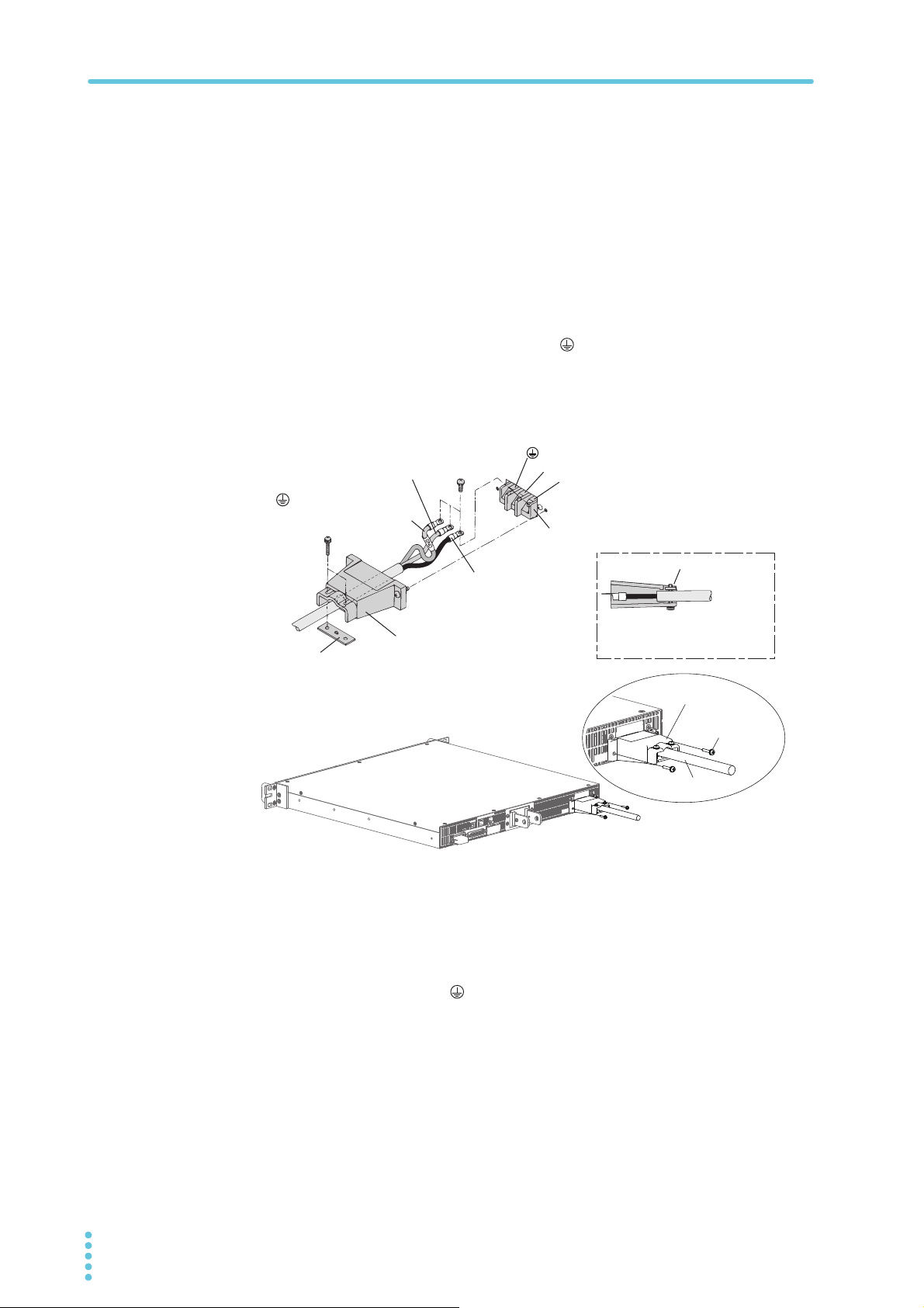
Connecting the Power Cord
INPUT terminal cover
Power cord
Screw
N
L
(GND)
Secure the insulated section
of the power cord in place
with a lock plate.
INPUT terminal cover
Lock plate
Lock plate
AC INPUT terminal
L: Black or brown
N: White or blue
(GND): Green or
green and yellow
Connection procedure
1
2
3
Check that the AC power line meets the nominal input rating of the product.
The product can receive a nominal line voltage in the range of 100 Vac to 240 Vac at
50 Hz or 60 Hz.
Check that the POWER switch is turned off.
Connect the power cord and the included INPUT terminal cover to the
AC INPUT terminal on the rear panel.
Be sure to connect the AC INPUT L, N, and (GND) terminals correctly.
Pass the power cord through the INPUT terminal cover, and fix the cord in place using
the lock plate and screws.
Use the PWX screws to connect the INPUT terminal cover in place.
Attach an appropriate crimping terminal to the switchboard end of the
4
power cord.
Turn off the switchboard breaker.
5
Connect the L, N, and (GND) wires of the power cord to the matching
6
terminals on the switchboard.
14 PWX
Turning the Power On
WARNING
CAUTION
See
See
See
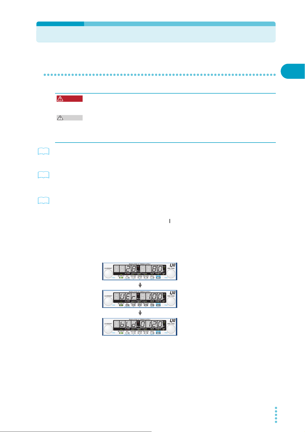
Firmware version display
(Version 1.00 in this example)
Rated voltage and rated current display
(The PWX750MLF is being used in this
example.)
Build number display
(Build number BLD 0120 in this example.)
Turning the POWER switch on
Risk of electric shock. Regardless of whether load cables are connected to the output
terminals, be sure to attach the OUTPUT terminal cover before turning the POWER
switch on.
You can use the CONFIG settings to set how the PWX series starts when you turn the
POWER switch on. Depending on the setting, the output may be turned on automatically
when the POWER switch is turned on. In case that you connect a load without setting OVP
and OCP to the appropriate values, the load may be damaged if output automatically turns
on at the PWX series power-on.
p.59
p.46
p.21
When you turn the POWER switch on for the first time after purchase, the PWX series starts
with its factory default settings. Subsequent times that you turn the PWX series on, it starts
with the panel settings (excluding the output on/off setting) that were in use immediately
before the POWER switch was turned off.
You can use the CONFIG settings (CF02) to select how the PWX series starts when the
POWER switch is turned on.
Check that the power cord is connected correctly.
1
Check that the OUTPUT terminal cover is attached.
2
When the product is shipped from the factory, the OUTPUT terminal cover is not
attached.
1
Installation and Preparation
Turn the POWER switch on ( ).
3
All the LEDs light, and then the voltmeter and the ammeter display the following
sequence of information: the rated voltage and rated current, the firmware version
number, and then the build number. Each item is displayed for approximately 1 second.
After a few seconds, the PWX series enters the operation standby state (the output
value is displayed).
Inrush current
When the POWER switch is turned on, an inrush current of up to 70 A flows. Check that sufficient current capacity is available in the AC power line or the switchboard, particularly if you
are using multiple PWX series and turning on their POWER switches simultaneously.
PWX 15

Rack Mounting
See
CAUTION
See
Turning the POWER switch Off
Flip the POWER switch to the ( ) side to turn the PWX series off.
The PWX series saves the panel settings (except the output on/off setting) that were in use
immediately before the POWER switch was turned off.
p.46
You can use the CONFIG settings (CF02) to select how the PWX series starts when the
POWER switch is turned on.
If the POWER switch is turned off immediately after the settings have been changed, the last
settings may not be stored.
After you turn the POWER switch off, wait at least 10 seconds after the panel display turns
off before you turn the POWER switch back on. Repeatedly turning the POWER switch on
and off at short intervals can cause damage to the inrush current limiter. Furthermore, this
will shorten the service life of the POWER switch and the internal input fuse.
Rack Mounting
p.122
You can use brackets or slide rails to mount the PWX series to a rack.
When you mount the PWX series to a rack, install the optional support angles (KRB1-PWX
SUPPORT ANGLE) to support the PWX series.
We recommend that you keep all pieces that you remove from the PWX series. You will need
these pieces if you remove the PWX series from the rack.
When using several PWX series power supplies together, such as for master-slave parallel
operation or series operation, mount them to a rack before use.
You can mount the PWX series to the Kikusui KRC series and KRO series racks.
16 PWX
Load Considerations
Set constant current
Ammeter reading (mean value)
Set constant current
Ammeter reading (mean value)
CAUTION
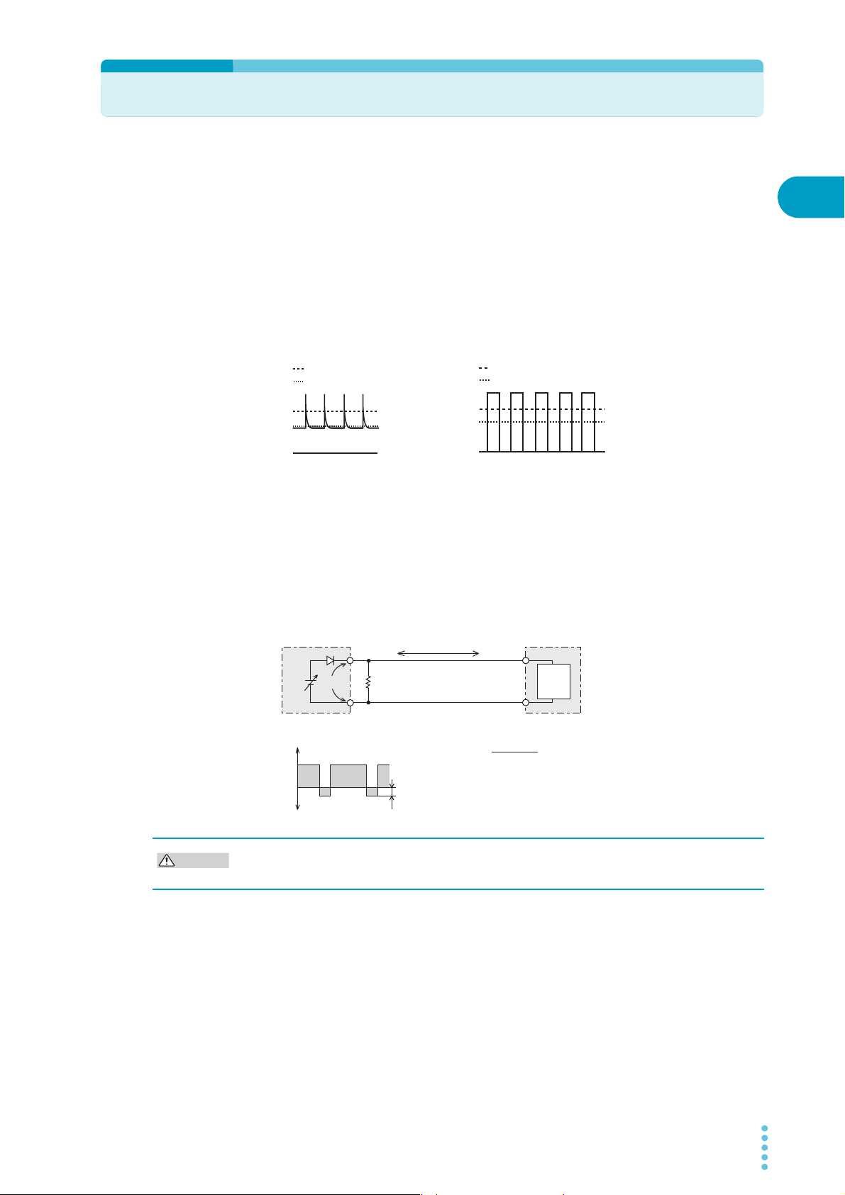
Note that the output will become unstable if the following types of loads are connected.
Loads with peak current or pulse-shaped current
The PWX series only indicates mean values. Even when the indicated value is less than or
equal to the set constant current, the peak values may exceed the set constant current. If this
happens, the PWX series is instantaneously put into constant-current mode, and the output
voltage drops.
For these types of loads, you must increase the set constant current or increase the current
capacity.
Load current with peaks Pulse-shaped load current
1
Installation and Preparation
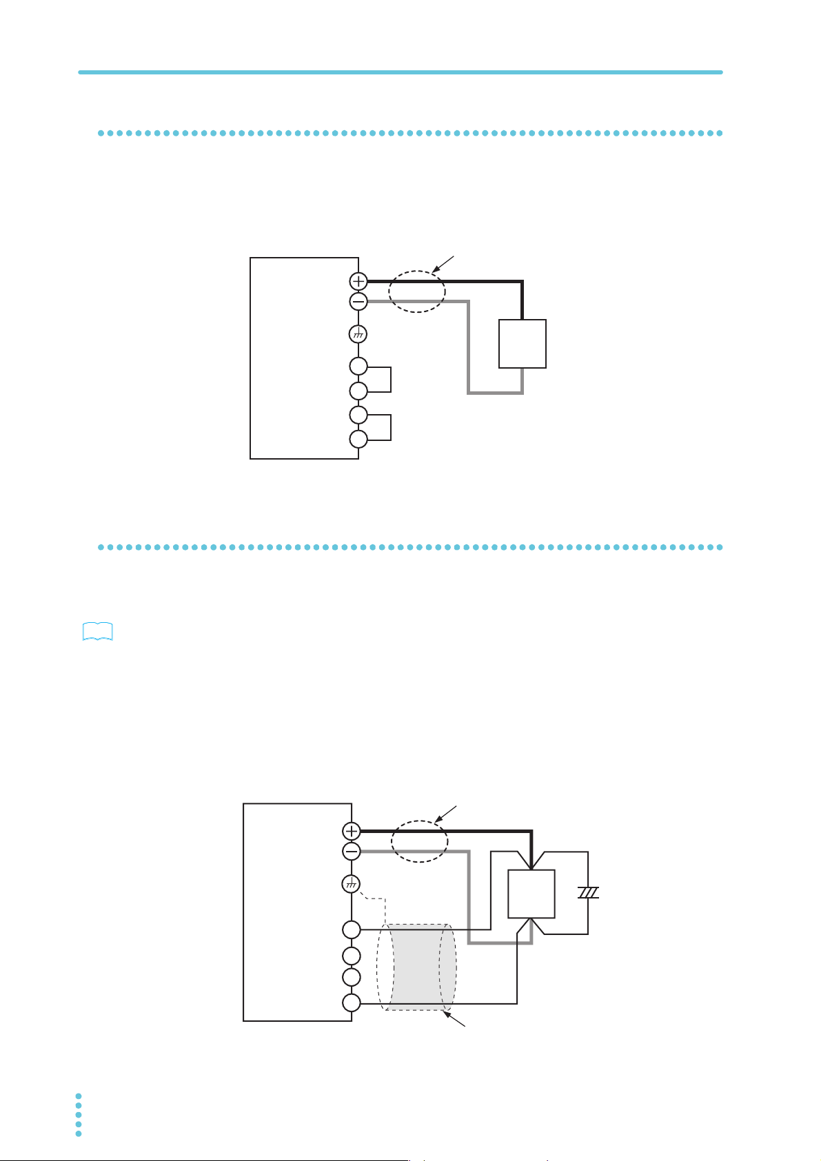
Loads that generate reverse current to the power supply
The PWX series cannot absorb reverse current from the load. Therefore, if a regenerative
load (such as an inverter, converter, or transformer) is connected, the output voltage
increases and becomes unstable. This can cause a malfunction.
For these types of loads, connect a resistor (RD) as shown in the following figure to bypass
the reverse current. However, the amount of current to the load decreases by Irp.
EO
Equivalent circuit of the PWX750ML
+IO
0
Output current
-IO
RD
Reverse current
IO
RD (in Ω) ≤
Irp
Use a resistor with sufficient rated power for RD. If a resistor with insufficient rated power for
the circuit is used, resistor R
D will burn out.
+
Load
Regenerative load
EO (in V)
Irp (in A)
RD: Reverse current bypass dummy load
E
O: Output voltage
Irp: Maximum reverse current
PWX 17
Load Considerations
CAUTION
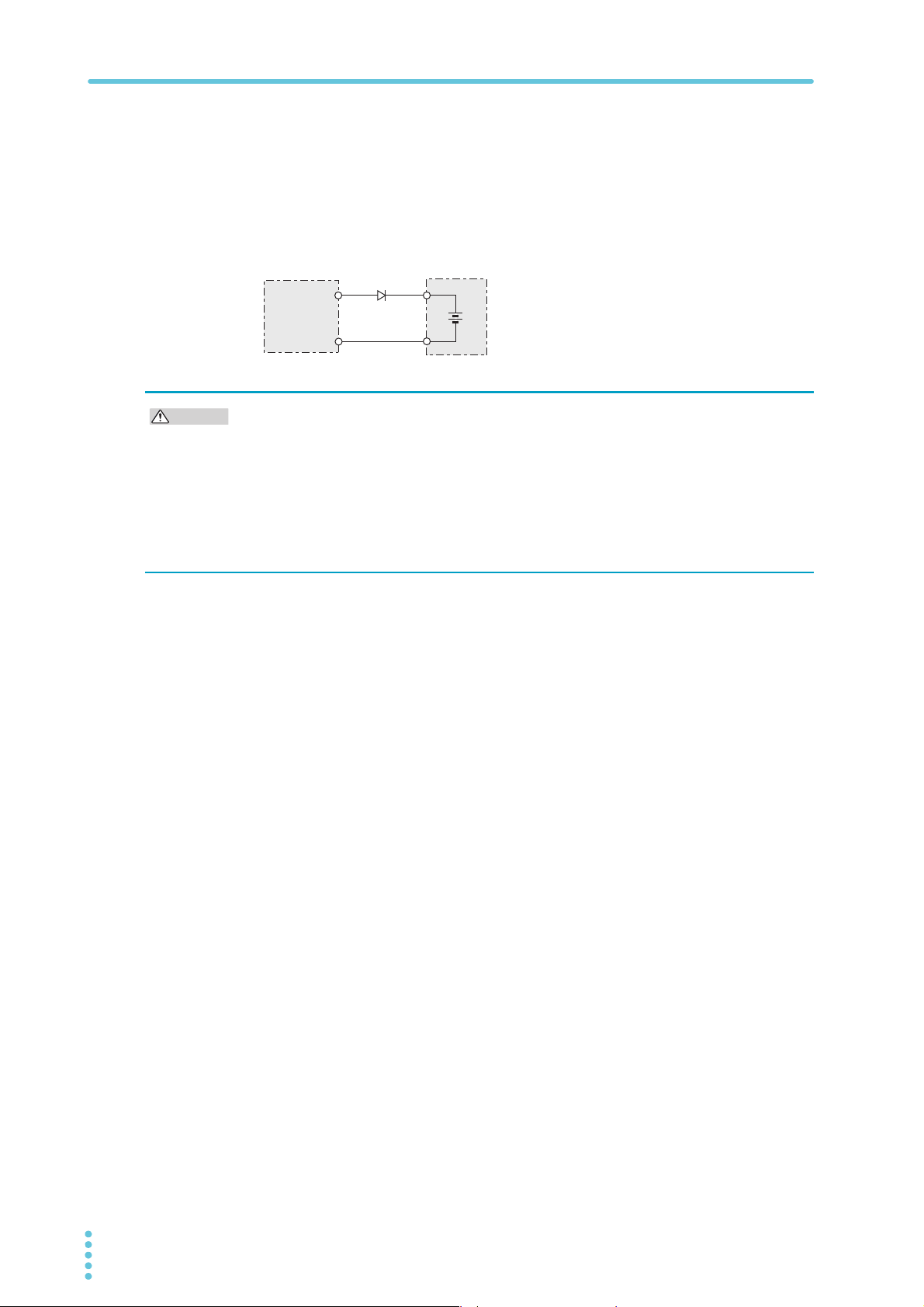
Loads with accumulated energy
Connecting a load with accumulated energy, such as a battery, to the PWX series may cause
current to flow from the load to the internal circuit of the PWX series. This current may damage the PWX series or reduce the life of the load.
For this type of load, connect a reverse-current-prevention diode (DRP) between the PWX
series and the load in series as shown in the following figure.
This cannot be used in conjunction with remote sensing.
D
RP
DRP: Reverse-current-protection diode
PWX750ML
Load with accumulated energy
• To protect the load and the PWX series, use a DRP that conforms to the following
specifications.
Reverse voltage withstand capacity:
At least twice the rated output voltage of the PWX series.
Forward current capacity:
Three to ten times the rated output current of the PWX series.
A diode with small loss.
• Be sure to take into account the heat generated by D
RP. DRP will burn out with inadequate
heat dissipation.
18 PWX

Load Cables
WARNING
Risk of fire.
• Use load cables whose capacity is adequate for the PWX series rated output current.
• The output connector and its surrounding area become hot. Use cables whose covers have heat resistance at 85 °C and higher.
Risk of electric shock.
• Use load cables whose rated voltage meets or exceeds the PWX series isolation voltage.
The cables’ allowable current depends on the insulation’s maximum allow-
able temperature.
A cable’s temperature is determined by the resistive loss based on the current, the ambient
temperature, and the cable’s external thermal resistance. The following table shows the current capacity of heat-resistant vinyl wires that have a maximum allowable temperature of
60°C, assuming that a wire is stretched out horizontally in air in an ambient temperature of
30°C. The current capacity must be reduced under certain conditions, such as when vinyl
cables that have a low heat resistance are used, when the ambient temperature is 30 °C or
greater, or when cables are bundled together and little heat is radiated.
Nominal cross-sectional
area [mm
2 14 (2.08) 27 10
3.5 12 (3.31) 37 -
5.5 10 (5.26) 49 20
8 8 (8.37) 61 30
14 6 (13.3) 88 50
22 4 (21.15) 115 80
30 2 (33.62) 139 -
38 1 (42.41) 162 100
50 1/0 (53.49) 190 -
60 2/0 (67.43) 217 -
80 3/0 (85.01) 257 200
100 4/0 (107.2) 298 -
125 - - 344 -
150 - - 395 300
200 - - 469 -
2
]
AWG (reference cross-
sectional area) [mm
2
Allowable current1 [A]
]
(Ta = 30 °C)
1
Installation and Preparation
Kikusui-recommended
current [A]
1 Excerpt from Japanese laws related to electrical equipment.
Taking measures against noise
When connecting wires that have the same heat resistance, separating the wires as much as
possible to increase heat radiation enables a greater amount of current to flow. However, wiring the + (positive) and - (negative) output wires of the load cable side by side or bundling
them together is more effective against unwanted noise. The Kikusui-recommended currents
shown in the above table are allowable currents that have been reduced in consideration of
the potential bundling of load cables. Use these values as a guideline when connecting load
cables.
Limitations of the remote sensing function
All wires have resistance. As the wire becomes longer or the current becomes larger, the voltage drop in the wire becomes greater. This results in a smaller voltage being applied at the
load end. The PWX series has a sensing function that compensates for this voltage drop up
to approximately 4 V for a single line. If the voltage drop exceeds this level, use wires that
have a greater cross-sectional area.
PWX 19
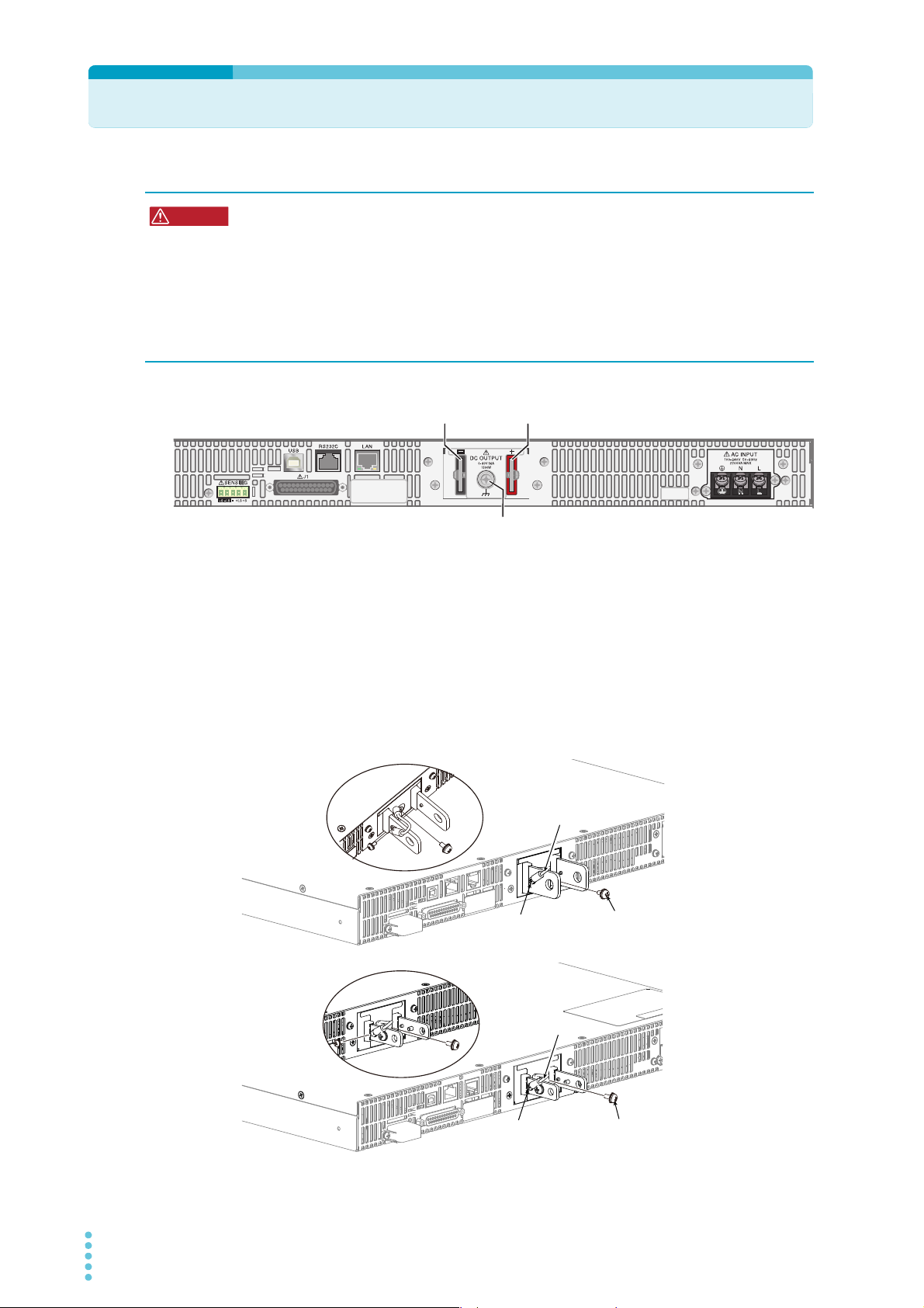
Connecting to the Output Terminals
WARNING
Chassis terminal
- (negative) terminal
+ (positive) terminal
The PWX1500ML is in this example.
Chassis
connection wire
Screw (M3)
Screw (M4)
Chassis
connection wire
Screw (M3)
Screw (M4)
Target model
PWX750LF
PWX750MLF
PWX1500L
PWX1500ML
Target model
PWX750MHF
PWX750HF
PWH1500MH
PWX1500H
Risk of electric shock.
• Turn the POWER switch off before you touch the OUTPUT terminals.
• Even if you turn the output off or turn the POWER switch off, if the bleeder on/off setting (CF11) is set to “oFF,” the voltage that was present when the output was on will
remain at the output terminals. Set the bleeder on/off setting to “on” before you
touch the output terminals.
• Regardless of whether load cables are connected to the output terminals, be sure to
attach the OUTPUT terminal cover before turning the POWER switch on.
Turn the POWER switch off.
1
Check that there is no voltage across the output terminals.
Connect one end of the included chassis connection wire to the chassis
2
terminal, and then connect the other end of the wire to the negative or
positive output terminal.
Use the screw on the PWX to connect the wire to the chassis terminal. Use the screw
on the output terminal to connect the wire to the output terminal.
20 PWX
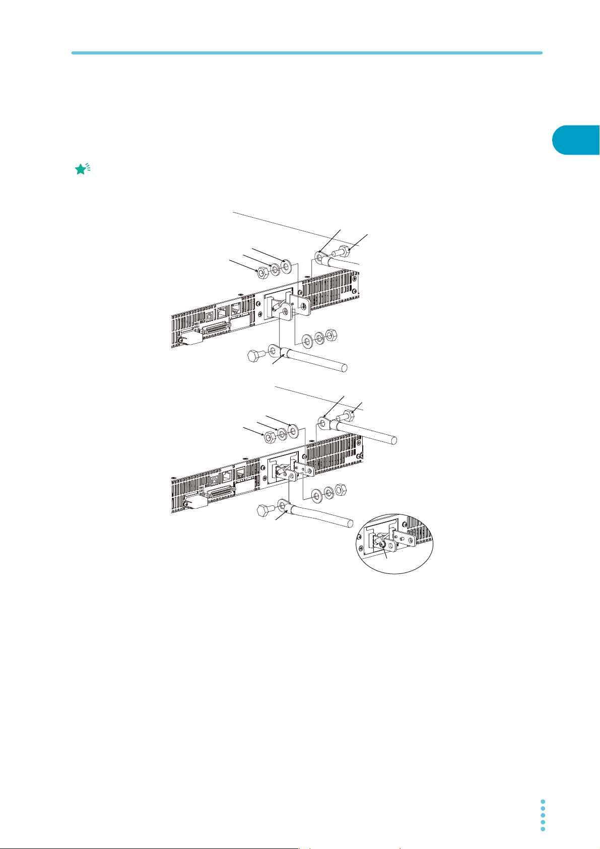
Memo
If you do not connect load
Spring washer
Washer
Nut
Bolt (M8)
Crimping terminal
Attach the cable to the inner side
of the crimping terminal.
Attach the cable to the outer side
of the crimping terminal.
Spring washer
Washer
Nut
Bolt (M5)
Screw (M4)
Crimping terminal
You can also use the center hole
depending on the load cables used.
Connection using the M8 bolt set
Examples for ø10 to ø18 wires
Target model
PWX750LF/ PWX750MLF
PWX1500L/ PWX1500ML
Connection using the M5
bolt set
Examples for up to ø10
wires
Target model
cables in the correct
orientation, you will not be
able to attach the
OUTPUT terminal cover.
Connecting to the Output Terminals
Attach crimping terminals to the load cables.
3
The output terminals have holes for connecting the load cables. Use crimping
terminals that are appropriate for the bolts that you are using.
Use the included bolt set to connect the load cables to the output termi-
4
nals.
Connect the positive cable to the positive output terminal and the negative cable to
the negative output terminal.
The orientation of the crimping terminals will vary depending on the wire diameter of
the load cables used.
1
Installation and Preparation
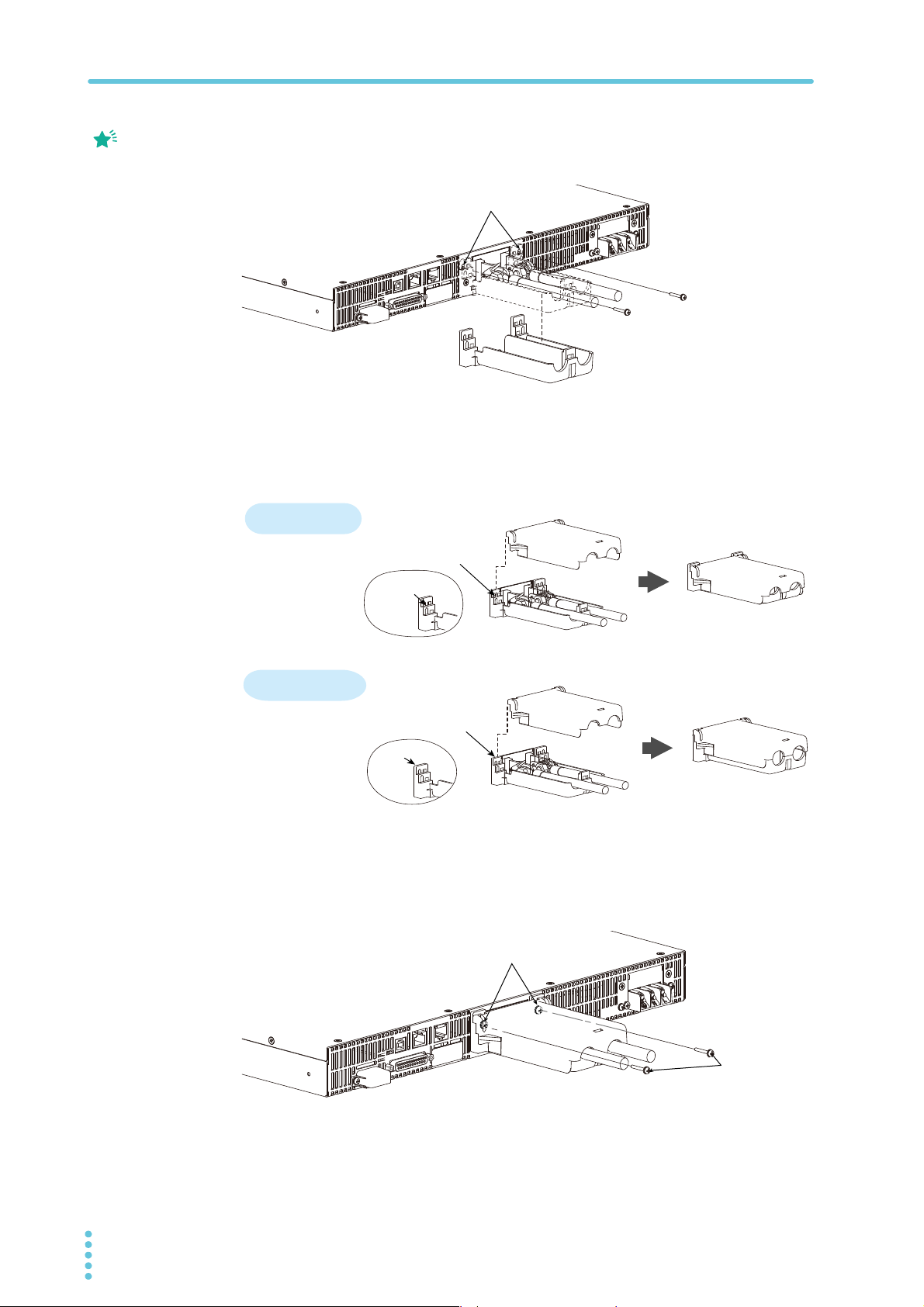
Attaching the OUTPUT terminal cover
You can adjust the diameter of the holes that the load cables pass through by changing the
positions in which the top and bottom halves of the OUTPUT terminal cover are put together.
There are two available positions. Use the appropriate position for the load cables that you
are using.
• For cables that are up to 10 mm in diameter: Put the top and bottom halves of the
• For cables that are between 10 mm and 18 mm in diameter: Put the top and bottom
1
OUTPUT terminal cover together so that the hole diameter is small.
halves of the OUTPUT terminal cover together so that the hole diameter is large.
Remove the screw that is attached next to the output terminals on the
PWX.
Use this screw to attach the OUTPUT terminal cover.
PWX 21
Connecting to the Output Terminals
Memo
Remove the screws, and then
line up the half of the cover.
Top half of the cove
Align the protrusion of
the top half of the cover
with the top section
of the protrusion of the
bottom half.
For thick load cables
Cover hole diameter:
10 mm to 18 mm
Cover hole diameter:
Up to 10 mm
Top half of the cover
Align the protrusion of
the top half of the cover
with the middle section
of the protrusion of the
bottom half of the cover.
Bottom half of the cover
Middle
section
Top section
After you have lined up the top and bottom halves
of the cover, use the screws to fix the cover in place.
Screws (M3)
Place the bottom half of the OUTPUT terminal cover underneath the load
2
The top and bottom
halves of the OUTPUT
terminal cover have
different shapes.
cables connected to the output terminals.
Align the tabs of the top half of the OUTPUT terminal cover with those of
3
the bottom half.
Align the tabs of the OUTPUT terminal cover according to the load cable diameter.
For thin load cables
Bottom half of the cover
Push the OUTPUT terminal cover against the rear panel, and then use
4
the PWX screws to fix the cover in place.
Make sure that the screws are securely fastened.
22 PWX
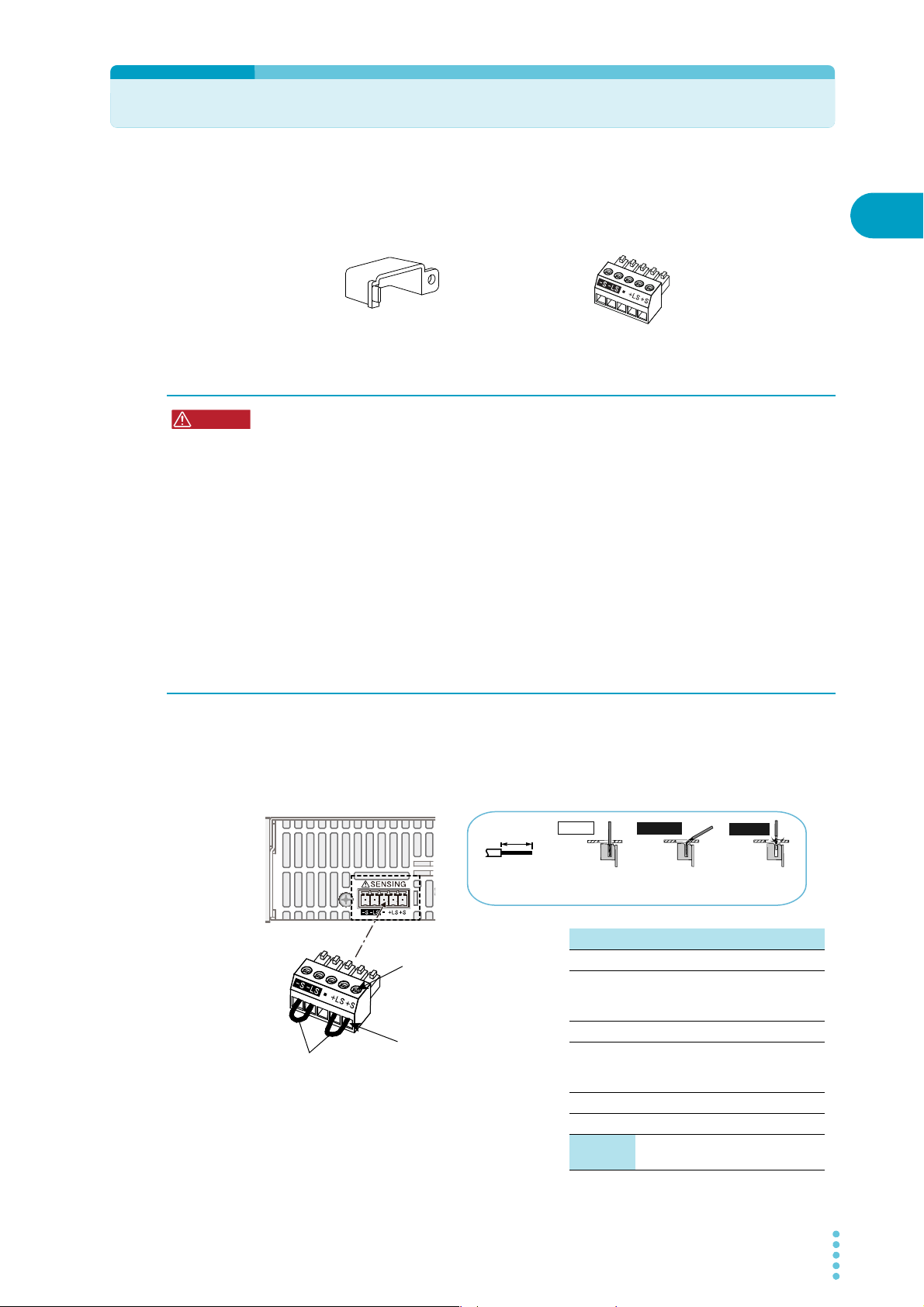
Sensing
84-61-7305
Terminal cover
Connector
P1-000-109
WARNING
Strip 7 mm (0.28 inches) of the
cable covering, and then insert
the cable here.
Incorrect
Incorrect
Correct
The wire itself is
in contact with
the chassis.
Wire scraps are
in contact with
the chassis.
Strip gauge
7 mm (0.28 inches)
Use this screw to fix the
cables in place so that they do
not come loose.
Local sensing jumpers
Te rm i na l Function
-S Negative remote sensing terminal
-LS
Negative local sensing terminal
Connected to the negative output
terminal
— Not connected
+LS
Positive local sensing terminal
Connected to the positive output
terminal
+S Positive remote sensing terminal
Sensing
cable
AWG28 to AWG16
When the PWX series is shipped from the factory, terminal cover and connector are attached
to the sensing terminals. For safety reasons, when not using the sensing terminals, be sure to
attach to terminal cover. If they are damaged or lost, contact your Kikusui agent or distributor.
Connecting the sensing cables
Risk of electric shock and damage to internal circuits.
• Never wire the sensing terminals while the POWER switch is turned on.
• Use sensing cables whose rated voltage is higher than the PWX series isolation volt-
• The sensing terminals are at approximately the same electric potential as the nega-
• Even if you turn the output off or turn the POWER switch off, if the bleeder on/off set-
• Regardless of whether local sensing or remote sensing is used, be sure to attach the
age. Protect the uncovered sections of the shielded cable by using insulation tubes
whose withstand voltage is greater than the PWX series isolation voltage.
tive output terminal. Insert the cables so that the wire strands do not touch the chassis when they stick out of the sensing terminal. Also, insert the cables so that the
stripped wires do not stick out of the terminal.
ting (CF11) is set to oFF, the voltage that was present when the output was on will
remain at the output terminals. Set the bleeder on/off setting to on before you touch
the sensing terminals.
sensing terminal cover before turning the POWER switch on.
1
Installation and Preparation
If the sensing cables come loose, the output voltage across the load may become unstable,
and an excessive voltage may be applied to the load. If an appropriate OVP trip point is set,
the OVP will trip before an excessive voltage is generated.
When you are finished with remote sensing, return the PWX series to local sensing mode.
PWX 23
Sensing
See
+
+
–
–
C
+LS
+S
-LS
-S
Connect an
electrolytic
capacitor
across the load
as necessary.
Output terminal
Chassis terminal
Sensing terminal
PWX
Load
Use twisted-pair wires for the load cables.
Make the cables as short as possible.
For the sensing cables, use twisted-pair
wires or shielded wires.
Local sensing
By factory default, the PWX series is set to local sensing (the rear panel sensing connector is
hard wired). The sensing point during local sensing is the output terminal. This method does
not compensate for the voltage drop in the load cable, so use this method when the load current is small or when you do not need to consider the load effect voltage.
PWX
Remote sensing
Remote sensing is a feature that stabilizes the output voltage across the load by reducing the
influence of voltage drops and other effects caused by the load cable resistance.
p.19
You can use the PWX series remote sensing feature to compensate up to 4 V for a single
line. Select a load cable that has sufficient current capacity to prevent the voltage drop in the
load cable from exceeding the compensation voltage.
When you perform remote sensing, set the voltage of the sensing point (across the load) so
that it does not exceed the rated output voltage. If you are performing remote sensing with
the voltage close to the maximum output voltage, the output is limited by the maximum output
voltage (105 % of the rated output voltage). Electrolytic capacitors may be required at the
sensing point (across the load).
To reduce the effect of noise, use twisted-pair wires or 2-core shielded wires. When you are
using shielded wires, connect the shield to the ground of the PWX series or the load.
Output terminal
Chassis terminal
Sensing terminal
+S
+LS
-LS
-S
Use twisted-pair wires for the load cables.
Make the cables as short as possible.
+
Load
–
24 PWX
Turn the POWER switch off.
1
Remove the sensing terminal cover and sensing connector from the rear
2
panel sensing terminals.
Sensing
Remove the local sensing jumpers from the sensing connector.
3
Remove 7 mm of the wire covering. Connect the negative sensing cable
4
to -S and the positive sensing cable to +S.
Use cable screws to securely fix the cables in place so that they do not come loose.
Firmly attach the sensing terminal cover and sensing connector to the
5
rear panel sensing terminals.
Turn the POWER switch on.
6
Electrolytic capacitor to connect across the load
If the wiring inductance component is large, the following symptoms may appear.
• The PWX series oscillates
If the wires used to connect to the load are long, the wiring inductance and capacitance
can cause phase shifting at a level that can not be ignored. This may lead to oscillation.
• The output fluctuates
If the load current changes drastically in a pulse-shaped pattern, the output voltage may
become large due to the wiring’s inductance component.
You can reduce the inductance component by twisting the load cables, which stabilizes the
voltage. However, if this does not rectify the problem, connect an electrolytic capacitor across
the load.
1
Installation and Preparation
Electrolytic capacitor to use
Capacity: 0.1 μF to a few hundred μF
Withstand voltage: At least 120 % of the rated output voltage of the PWX series
LF/ L type MLF/ ML type MHF/ MH type HF/ H type
36 V or more 96 V or more 276 V or more 780 V or more
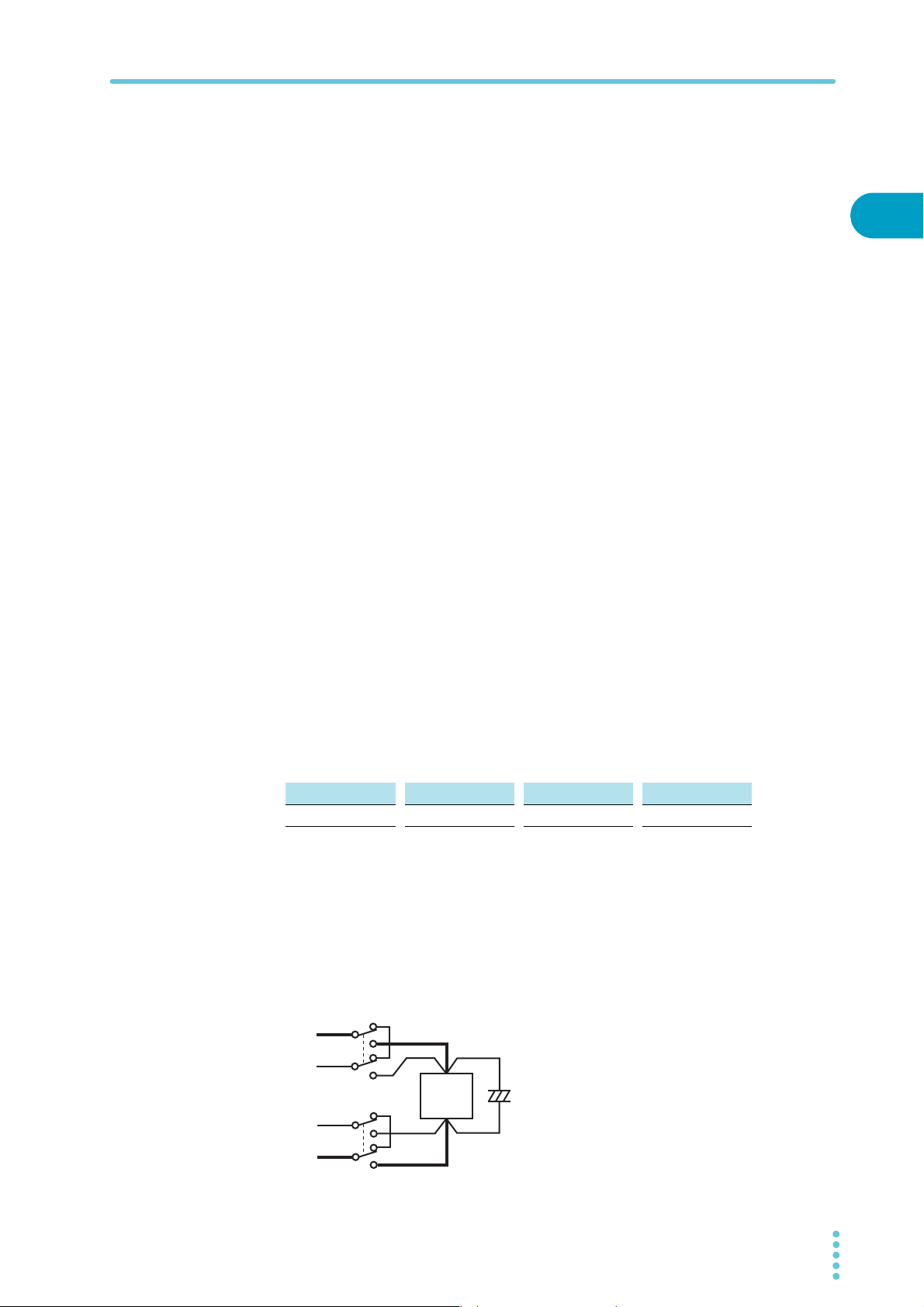
If you are inserting a mechanical switch between the PWX series and the
load
If you want to connect and disconnect the load using a mechanical switch that is inserted
between the PWX series and the load, be sure to include switches in the sensing cables as
shown in the following figure and turn on and off the load cable and the sensing cables simultaneously. Before you turn the mechanical switch on or off, be sure to turn the output or the
POWER switch off.
+
+S
–S
–
S
+
Load
–
+
C
–
PWX 25

26 PWX
This page is intentionally blank.

Basic Functions
This chapter describes how to turn the output on and off and the basic operations that
you can perform from the front panel.

Measured Value Display and Setting Display
See
Lit
The voltage and current displays have the following two states.
• Measured value display
• Setting display
In addition to the voltmeter and ammeter, the PWX series can display the power, the set OVP
or OCP, and the system configuration.
Measured value display
The present output voltage and output current are displayed. In this situation, the SET key
LED is off.
p. 35
You can change the output voltage and output current in the measured value display.
Power display
In the measured value display, press PWR DSPL to display the output power on the ammeter.
The output power is calculated from the measured output voltage and the measured output
current.
When the power is being displayed, the PWR DSPL key lights. Press PWR DSPL again to
turn off the LED and return to the measured value display.
Lit
Setting display
Press SET to light its LED and display the present output voltage and output current settings.
Press SET again to return to the measured value display.
When you recall a preset memory entry, the values stored in the preset memory entry are displayed on the panel.
28 PWX
Panel Operations
Decrease IncreaseIncrease Decrease
See
Memo
Overvoltage protection and overcurrent protection setting display
Press OCP•OVP to light its LED and display the present overcurrent protection and overvoltage protection settings.
Lit
System configuration setting display
Press CONFIG to light its LED and display the present system configuration settings.
Panel Operations
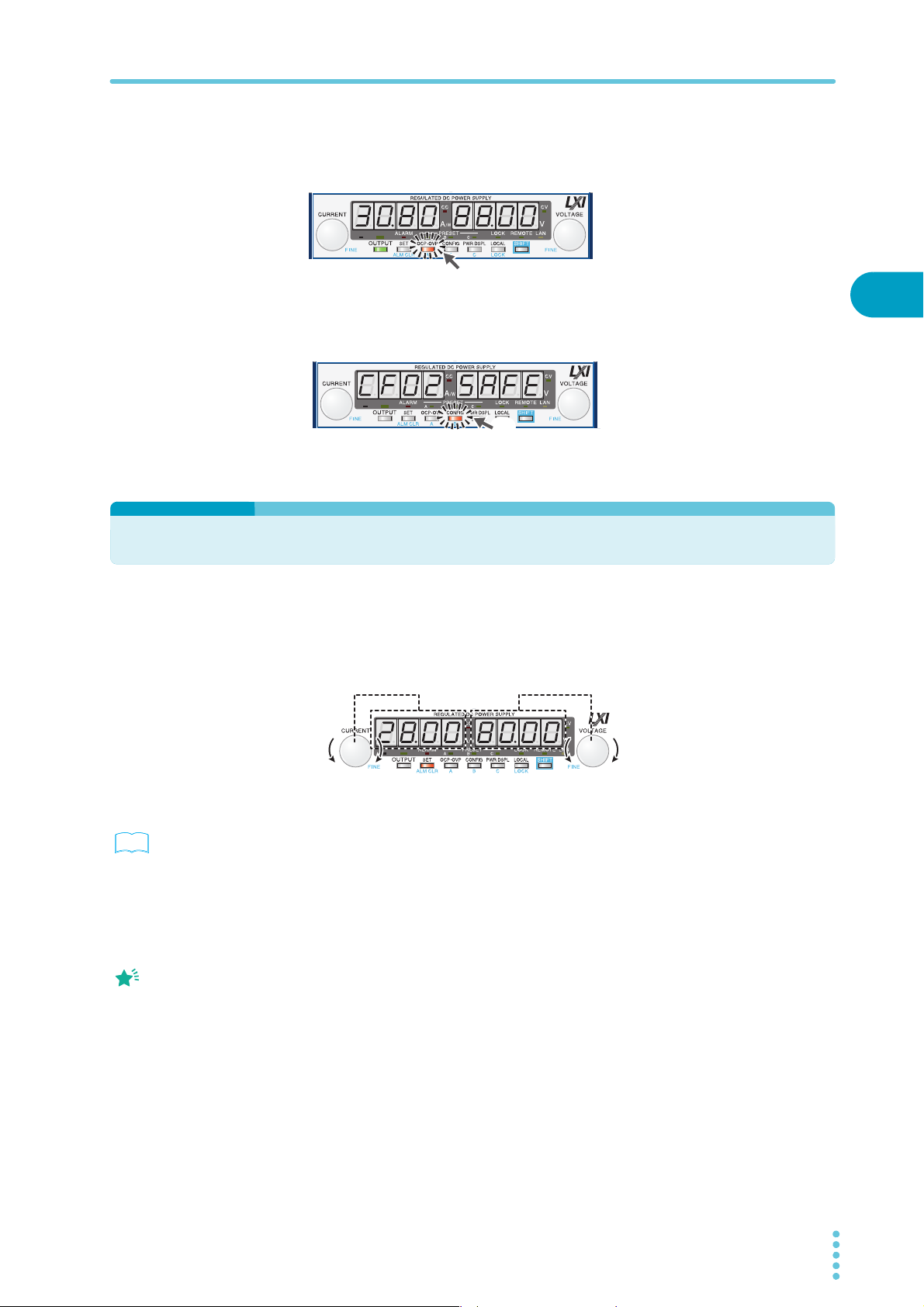
Measured value display, setting display, and set OVP/OCP display
Turn the VOLTAGE knob to change the voltage. Turn the CURRENT knob to change the current.
2
Lit
Basic Functions
p. 38
When you set a value, it is
convenient to first use
normal resolution to set
the value roughly and
then switch to fine
resolution to set it
precisely.
Press SET to switch to the setting display, and then change the output voltage and output
current while you view their actual settings.
You cannot set the output voltage to a value that is 95% of the OVP trip point or higher. You
cannot set the output current to a value that is 95% of the OCP trip point or higher.
The displayed current or voltage may not change even if you turn the CURRENT or VOLTAGE knob. In this situation, the values are being changed at a finer resolution that which is
being displayed. The display will change when the amount that you change the value by
reaches the smallest display digit of the set voltage or current.
Fine adjustment
You can change the resolution of the VOLTAGE and CURRENT knobs.
Hold down SHIFT while you turn the VOLTAGE knob or CURRENT knob to make small
changes to the value.
PWX 29
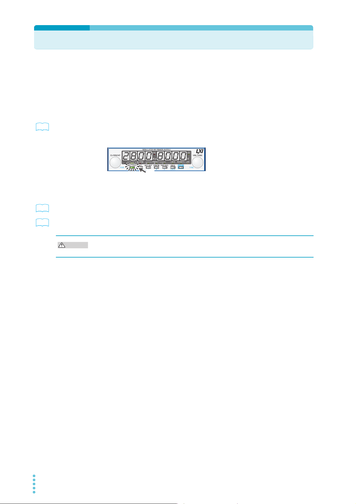
Output Operations
See
Lit
Output on
See
See
CAUTION
The output turns on and off each time you press OUTPUT. When output is on, the OUTPUT
LED in the display area lights. When the output is off, the OUTPUT LED in the display area
turns off.
When the output is on, output is generated at the present set values.
If you change the settings while the output is on, the changes are applied immediately to the
output. If the output is off, the setting display will appear (the SET key lights) as soon as you
change the settings. Then, you can press OUTPUT to output using the new settings.
p. 48 , p. 71
p. 59
p. 38
You can use external control to turn the output on and off.
You can use the CONFIG settings to set the output-on startup state (CF12: prioritize CC or
CV).
Output on or off when the PWX series turns on
In the factory default settings, output is off when the PWX series turns on. Using a CONFIG
parameter (CF02:Forc), you can set the PWX series so that output is turned on at power on.
If you set the PWX series so that output is turned on at power on, be sure to check the OVP
trip point setting before you turn the PWX series off.
If you change the load, it may be damaged if the PWX series’s OVP and OCP settings are
not correct.
30 PWX
 Loading...