

Page 1
PART NO. Z1-005-550, IA004953
Jan. 2017
Features
Setup Guide
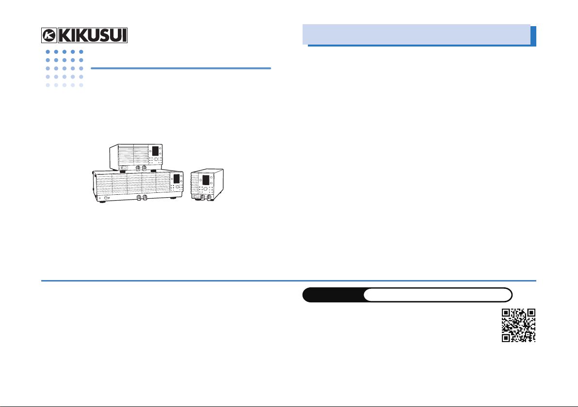
Regulated DC Power Supply PWR Series
400W Type 800W Type 1600W Type
PWR400L PWR800L PWR1600L
PWR400M PWR800M PWR1600M
PWR400H PWR800H PWR1600H
Thank you for purchasing the PWR regulated DC power supply series.
The PWR Series are constant voltage/current automatic crossover
power supplies that are capable of delivering voltages and currents
in a wide operating range within the rated output power.
KIKUSUI ELECTRONICS CORP.
1-1-3, Higashiyamata, Tsuzuki-ku, Yokohama, 224-0023, Japan
TEL: +81-45-593-0200 Fax: +81-45-593-7571
The contents of this manual may not be reproduced, in whole or in part, without the
prior consent of the copyright holder.
The specifications of this product and the contents of this manual are subject to
change without prior notice.
• Power-factor improvement circuit
The power-factor improvement circuit reduces the effects of har-
monic currents on the power line.
• High efficiency
The high power conversion efficiency reduces the cost of power
and the cost of heat radiation design during system configuration.
• Communication functions
Equipped with a digital remote control function through TP-BUS
(Twist Pair-BUS) communication (The total length of TP-BUS is
200 m). By combining with Kikusui’s PIA4800 Series Power Supply Controller, systemization for applications such as an automatic tester is possible.
• Master-slave operation
Output voltage or output current can be expanded by connect-
ing multiple power supplies of the same model in series (only
on the L type) or in parallel. This feature allows slave units to be
controlled from a single master unit.
WEBSITE
The newest version of the PWR manual can be downloaded
from Download service of Kikusui website.
© 2012
http://www.kikusui.co.jp/en
Page 2
Checking the Package Contents
Accessories
.
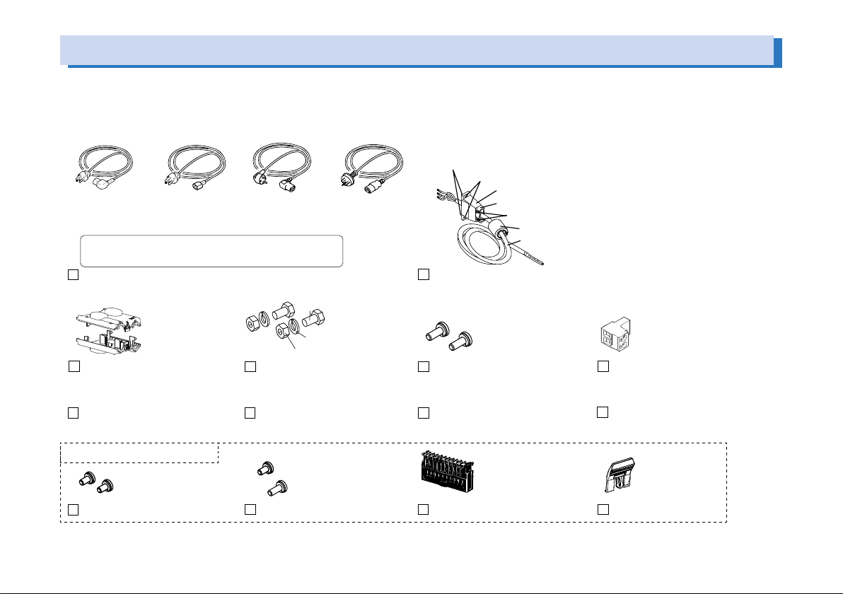
When you receive the product, check that all accessories are included and that the accessories have not been damaged during transportation. If any of the accessories are damaged or missing, contact your Kikusui agent or distributor. The power cord varies depending on the type.
or
Plug:NEMA5-15
Rating:125Vac/10A
[85-AA-0003]
The power cord that is provided varies depending on
the destination for the product at the factory-shipment.
Power cord for the 400W/800W type
OUTPUT terminal cover
CD-ROM (1 pc.)
Plug:NEMA5-15
Rating:125Vac/10A
[85-10-0740]
1 set
[Q1-500-077]
or
Pulg: CEE7/7
Rating: 250Vac/10A
[85-10-1070]
2 sets
M8 output terminal screws
Safety information (1 pc.)
or
Pulg: GB1002
Rating: 250Vac/10A
[85-10-0790]
[M1-100-011]
[M5-101-007]
[M4-100-007]
Accompanying nuts: [M8-500-003] 2 pcs.
Accompanying screws A: [M3-112-015] 2 pcs.
Cable clamp: [P1-000-055] 1 pc.
Fastening plate: [D6-750-001] 1 pc.
Accompanying screws B: [M3-112-017] 2 pcs.
EMI core: [96-01-0180] 1 pc.
Cable: [85-10-1010] 1 pc.
Power cord for the 1600W type (with cable clamp and no plug)
2 pcs.
[M3-112-026]
M4 output terminal screws
Setup Guide (This guide, 1 pc.) Quick Reference
1 pc.
[84-61-5102]
TP-BUS connector
English 1 pc. , Japanese 1 pc
These parts are installed in body.
2 pcs.
[M3-112-012]
M3 sensing terminal screws
1 pc. [M3-112-012]
1 pc. [M3-112-015]
M3 screws for chassis connection wire
1 pc.
[84-49-0110]
J1protection socket
1 pc.
[83-06-5060]
J1 lock lever
2 PWR Series Setup Guide
Page 3
About the PWR Manual
The PWR manual is intended for users of the PWR regulated DC power
supply series or persons teaching other users on how to operate them.
The manual assumes that the reader has knowledge about electrical
aspects of regulated DC power supplies.
The PWR manual comprises the Setup Guide (this guide), the User’s
Manual (Basic operation, External control, Parallel/Series operation,
Maintenance, and Specifications), the Connecting & Programming
Guide, the Quick Reference, and the Safety information.
The user's manual and the connecting & programming guide are provided on the accompanying CD-ROM.
Adobe Reader is required to view the PDF files. Microsoft Internet
Explorer or Google Chrome is required to view the HTML files.
Put the included CD-ROM into the CD-ROM drive. In a few moments, a
start window will appear. If the start window does not appear, open the
CD-ROM folder in Windows Explorer, and then double-click index.html
to display the start window.
Every effort has been made to ensure the accuracy of the manual. However, if you have any questions or find any errors or omissions, please
contact your Kikusui agent or distributor.
If you find any misplaced or missing pages in the manual, it will be replaced. If the manual gets lost or soiled, a new copy can be provided
for a fee. To replace or purchase a manual, please contact your Kikusui
agent or distributor. At that time, inform your agent or distributor of the
“Part No.” written on the front cover of this manual.
In the manual, the PWR Series Regulated DC Power Supply is also referred to as the PWR Series and the PWR.
The display illustration used in the manual may differ from the actual
displays that appear on the PWR. The screen captures are merely examples.
The PWR series is classified into three types depending on the output
capacity. It is also classified into three types depending on the output
voltage.
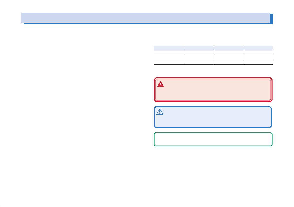
L type (80 V) M type (320 V) H type (650 V)
400W type PWR400L PWR400M PWR400H
800W type PWR800L PWR800M PWR800H
1600W type PWR1600L PWR1600M PWR1600H
The following markings are used in the explanations in the text.
WARNING
Indicates a potentially hazardous situation which, if ignored, could result in death or serious injury.
CAUTION
Indicates a potentially hazardous situation which, if ignored,
may result in damage to the product or other property.
- Note Indicates information that you should know.
SHIFT+switch name (marked in blue)
Indicates an operation in which a switch marked in blue is pressed
while holding down the SHIFT switch.
C-x: x
The first two characters “C-” indicate a configuration setting, and the
next one-digit number indicates the CONFIG parameter number. The
character after the colon indicates the selected setting.
PWR Series Setup Guide 3
Page 4
L
M
H
Output voltage [V]
Output current [A]
Ambient temp. [°C]
Output current [%]
(
e
Description of Operation
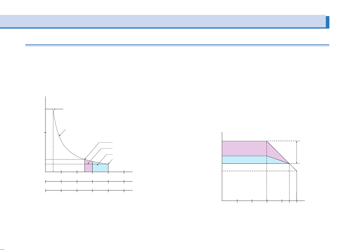
The PWR is a constant voltage/current regulated DC power supply
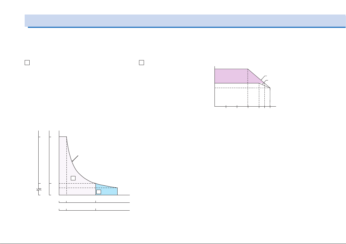
that is capable of delivering voltages and currents in a wide operating range within the rated output power. Figure shows the operating area of the 400 W type.
A
the extended operating area. The extended operating area is valid
only on the L type.
If the PWR is configured in way that satisfies the equation output
voltage x output current ≤ rated output power, the PWR operates as
a conventional constant voltage/current power supply.
If the PWR is configured in a way that satisfies the equation output
voltage x output current > rated output voltage, the actual output is
limited by the power limit (approx. 105% of the rated output power)
and the output voltage or output current varies depending on the
load value.
4 PWR Series Setup Guide
in the figure indicates the rated operating area, and B indicates
320
650
PWR400H
PWR400M
80
Rated output poer (400W) line
PWR400L
A
16
64
200
0
10
0
0
50
0
1.25 6.25
0
0.615 2
type only
L
B
25 40
PWR400
PWR400
PWR400
The output current must be derated with respect to the temperature
at ambient temperatures greater than or equal to 45 ºC (30 ºC when
operating in the extended operating area) on the L type and 40 ºC
on the M/H type.
160
Rated output current)
100
Extended operating
area
80
Rated operating area
0
10 20 4530 40 50
L type
M/H typ
Page 5
Extended operating area (L type only)
v
a
Ambient temperature [°C]
(Rated output current)
Extended
operating
Of the output current setting range of the PWR as illustrated in
figure below, the range between the rated output current and the
maximum output current (160 % of the rating) is the extended operating area. The specifications of load fluctuation, input fluctuation,
ripple/noise, and so on are not met in the extended operating area.
The extended operating area is divided into the continuous extended operating area and the intermittent extended operating area.
oltage [V]
Output
80
50
16
10
Rated output voltage
Rated output power line
Rated output current
Continuous extended operating area
Intermittent extended operating are
Maximum output current
Rated operating area
50 10 20 25 30 40 50
10 20 40 50 60 80 100
20 40 80 100 120 160 200
Extended
operating area
Output current [A]
PWR400L
PWR800L
PWR1600L
• Extended operating area
Continuous output is possible. At ambient temperatures greater
than or equal to 30 ºC, the output current must be derated with
respect to the temperature.
• Continuous extended operating area
The output duration is limited.
Guideline of the time duration of operation (When operating by
itself with no devices that generate heat around the PWR.)
Maximum Output Duration: 10 minutes
Pause Duration: At least twice the output duration
When using the PWR in the extended operating area, pay attention
to the ambient temperature, preset current, and output duration.
Output current [%]
160
Intermittent extended
operating area
120
Continuous extended operating area
100
80
Rated operating area
0 10 20 4530 40 50
area
PWR Series Setup Guide 5
Page 6
Precautions Concerning Installation
4
Connecting the Power Cord
This product cannot be used while it is on its side.
The feet on the side panel of the 1600 W type are for temporarily
laying the unit on its side before carrying the unit by the handle.
Do not use or store the unit on its side as it may tip over.
Safety Precautions
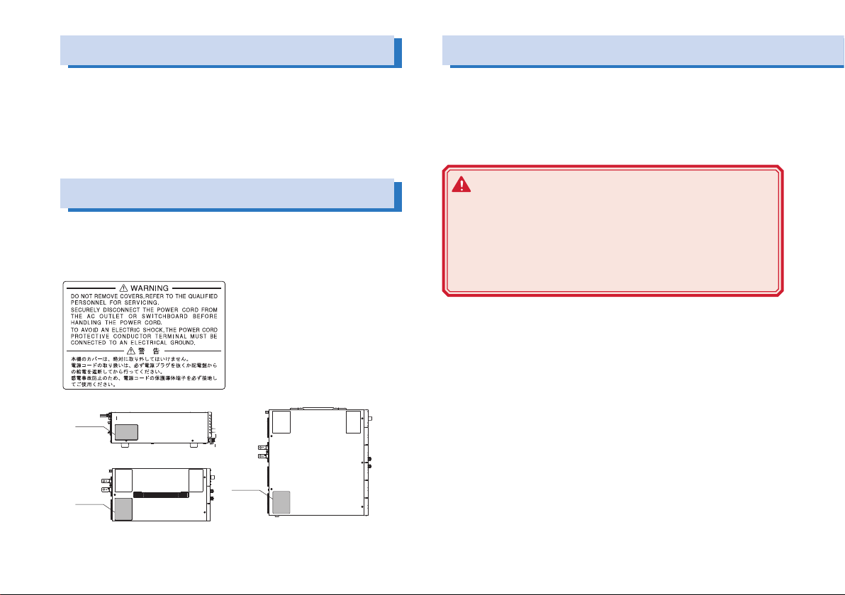
There is a warning label affixed to the product. If this label tears or
falls off, replace with a new label. If you need a new label, contact
your Kikusui agent or distributor.
The power cord provided with the PWR varies depending on the
output capacity type. For the procedure to connect the power cord,
see the respective section for each type. This product is designed
as an equipment of IEC Overvoltage Category II (energy-consuming
equipment supplied from the fixed installation).
WARNING
Possible electric shock.
• This product is an IEC Safety Class I equipment
(equipment with a protective conductor terminal). Be
sure to ground the product to prevent electric shock.
• Connect the ground terminal to earth ground.
00W type left side panel
Label
800W type top side panel
Label
1600W type top panel
Label
6 PWR Series Setup Guide
Page 7
400 W and 800 W types
- Note -
• Use the supplied power cord to connect to the AC line. If the
supplied power cord cannot be used due to the rated voltage
or the plug shape, replace it with an appropriate power cord of
length 3 m or less.
• The rated voltage of the power cord with a three-prong plug
that comes with the PWR is 125 VAC. If you are using an input
power supply of a 200-V system, exchange the power cord with
one that is suitable for the input voltage.
• Have a qualied engineer select the appropriate power cord. If
obtaining a power cord is difcult, consult your Kikusui agent or
distributor.
• The power cord with a three-prong plug is used to disconnect the
PWR from the AC line in an emergency. Connect the power plug to
an easily accessible power outlet so that the plug can be removed
from the outlet at any time. Be sure to allow enough space around
the power outlet.
• Do not use the supplied power cord on other instruments.
Check that the AC power supply meets the nominal
1
input rating of the PWR.
The voltage that can be applied is any of the nominal power
supply voltages in the range of 100 Vac to 240 Vac. The frequency is 50 Hz or 60 Hz.
Check that the POWER switch is turned off.
2
Connect the power cord to the AC inlet on the rear
3
panel.
Insert the power plug to a properly grounded power
4
outlet.
PWR Series Setup Guide 7
Page 8

B
t
Breaker indication example
Connecting the Power Cord (Cont.)
1600 W type
The power cord that is included with the 1600 W type can be used
on either a 100-Vac or 200-Vac system.
Circuit breaker of switchboard requirement
• Rated current: 30 A (100 V system) / 15 A (200 V system)
For safety, breakers whose rated current exceeds the specified
WARNING
• Possible electric shock. Turn off the circuit breaker of
switchboard before connecting the cord.
• Possible Fire. Have a qualified engineer connect the
power cord to the switchboard. The breaker of switch-
current cannot be used
• Dedicate the circuit breaker for the PWR.
• Keep the switchboard easily accessible at any time.
• Require labeling to identify that the circuit breaker is dedicated
for the PWR and disconnecting device.
board is required to meet requirement.
PWR1600L
30 A
CAUTION
reaker dedicated
o the PWR1600L
Switchboard
Inside the product, protective circuits including input fuses
are connected to match the polarity of the input terminal.
Make sure the colors of the wires connected to the corre-
sponding input terminals (L, N, and
- Note -
(GND)) are correct.
L
N
Connection to the switchboard (PWR1600L example)
Supplied power cord
L
N
PWR1600L
Turn off the circuit breaker of switchboard to disconnect the PWR
from the AC line in an emergency.
8 PWR Series Setup Guide
Page 9

Procedure to connect the power cord
(GND)
AC INPUT terminal block
N
N: White or blue
(GND): Green or green/yellow
L
Check that the AC power line complies with the input
1
rating of the PWR.
The voltage that can be applied is any of the nominal power
supply voltages in the range of 100 VAC to 240 VAC. The
frequency is 50 Hz or 60 Hz.
L: Black or brown
Fastening plate
Fastening plate
PWR Series Setup Guide 9
Cable clamp
Fix the covered part of the power
cord with the fastening plate.
Check that the POWER switch is turned off.
2
Connect the power cord provided to the AC INPUT
3
terminal block on the rear panel as shown in gure
Attach crimping terminals at the switchboard end of
4
the power cord.
Turn the switchboard breaker off.
5
Connect the power cord to match the L, N, and
6
GND) of the switchboard.
Page 10

A/
W
Turning the Power On
Turn the power on without the load connected.
CAUTION
The CONFIG parameters can be set so that the output is automatically turned on when the POWER switch is turned on.
When this function is enabled, the PWR powers up with the
output turned on even if the output was off when the PWR
was turned off the last time. There is a possibility that a load
may break, if you connect a different load and turn the POWER and output on simultaneously without changing the OVP
and OCP settings to appropriate values.
Turning the Power switch on
Check that the POWER switch is turned off.
1
Check that the power cord is correctly connected.
2
Turn the POWER switch on.
3
Push the ( | ) side of the POWER switch to turn the PWR on.
If an odd sound, odd odor, fire, or smoke occurs around or
in the PWR, remove the power plug from the outlet or turn
the switchboard breaker off.
The voltmeter and ammeter show the firmware version for
approximately 1 second. After a few seconds, the PWR is
ready for operation (displays the output value).
V/
W
OUTPUT
If the POWER switch is turned on for the first time after purchasing
the PWR, the PWR starts up in a factory default condition. For all
other cases, the PWR starts up using the settings that existed when
the POWER switch was turned off the last time.
Version display at power-on (ver.1.00 example)
10 PWR Series Setup Guide
Page 11
Inrush current
An inrush current flows when the POWER switch is turned on. If you
are planning to use several PWRs and turn on their POWER switches simultaneously, check that the AC power line or the switchboard
has sufficient capacity. For the inrush current of each model, see
“Specifications” of the user’s manual on the accompanied CDROM.
Turning the POWER switch off
Push the (○) side of the POWER switch to turn the PWR off.
The PWR stores the panel settings (excluding output on/off condi-
tion) immediately before the POWER switch is turned off. For these
items, the PWR starts up using the settings that existed when the
POWER switch was turned off the last time.
If the POWER switch is turned off immediately after changing the
settings, the last settings may not be stored.
CAUTION
When turning the POWER switch off and then back on, allow
at least 10 seconds after the panel display lights out. Repeated on/off of the POWER switch at short intervals can cause
damage to the inrush current limiter and shorten the service
life of the POWER switch and internal input fuse.
PWR Series Setup Guide 11
Page 12
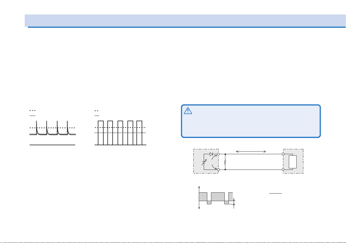
Load Considerations
Load current with peaks
Ammeter reading (average value)
Note that the output will become unstable if the following types of loads are connected.
Load current with peaks and pulse-shaped load
current
The PWR indicates mean values. Even when the indicated value
is less than the preset current value, the peak values may actually
exceed the preset current value. If this happens, the PWR is instantaneously put into constant-current operation mode, and the output
voltage drops accordingly.
For these types of loads, you must increase the preset current
value or increase the current capacity.
Preset constant current value
Ammeter reading (average value)
Preset constant current value
Pulse-shaped load current
Load that generates reverse current to the power
supply
The PWR cannot absorb reverse current from the load. Therefore, if
a regenerative load (such as an inverter, converter, or transformer)
is connected, the output voltage increases and becomes unstable.
For these types of loads, connect a resistor (RD) as shown in figure
below bypass the reverse current. However, the amount of current
to the load decreases by Irp.
CAUTION
Select a resistor with sufcient rated power for RD. If a resistor with insufcient rated power for the circuit is used, RD may
burn out.
IO
-
EO
RD
Equivalent circuit of the PWR Regenerative load
+IO
0
-IO
Output current
waveform
Reverse current
Irp
+
Load
[V]
E
RD[Ω] ≤
I
RD: Reverse current bypass dummy load
EO: Output voltage
Irp: Max. reverse current
O
[A]
rp
12 PWR Series Setup Guide
Page 13
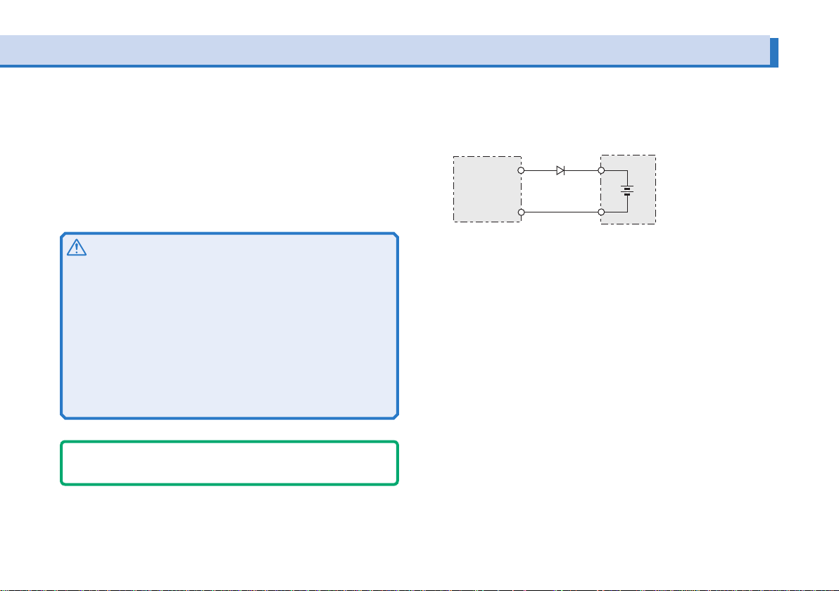
Load with accumulated energy
Connecting a load with accumulated energy, such as a battery, to
the PWR may cause current to flow from the load to the internal circuit of the PWR. This current may damage the PWR or degrade the
service life of the load.
For this type of loads, connect a reverse-current-prevention diode
(DRP) between the PWR and the load in series.
CAUTION
• To protect the load and the PWR, select a DRP that complies with the following conditions.
Reverse voltage withstand capacity of at least twice the
rated output voltage of the PWR.
Forward current capacity that is 3 to 10 times the rated output current of the PWR.
A diode with small loss.
• Be sure to take into account the heat generated by DRP.
DRP may burn out without adequate heat dissipation.
- Note -
Cannot be used in combination with remote sensing.
D
RP: Reverse-current-prevention diode
DRP
PWR Load with accumulated energy
PWR Series Setup Guide 13
Page 14
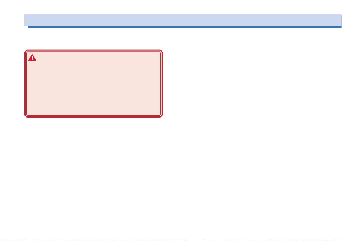
Load Wire
Note the following points concerning the wire used to connect the
load.
WARNING
• To prevent re, use a load wire with sufcient current
capacity with respect to the rated output current of the
power supply.
• Possible electric shock. Use a load wire with a higher
voltage rating than the isolation voltage of the PWR.
For the isolation voltage of each model, see “Specications” of the user's manual on the accompanied CDROM.
Current capacity of the load wire
If the current rating exceeds the maximum rated output current, the
wire will remain intact even if the load is short-circuited. Load wires
must be rated to carry the maximum rated output current of the
PWR.
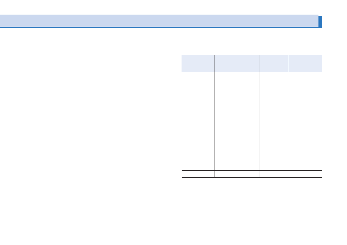
Allowable current of the wire dependent on the
maximum allowable temperature of the cable insulation
The wire temperature is determined by a current-caused resistance
loss, ambient temperature, and thermal resistance to the outside.
Table shows the allowable capacity of current that can flow through
a heat-resistant PVC wire (single wire) having a maximum allowable
temperature of 60 ºC when the wire is stretched horizontally in the
air at an ambient temperature of 30 ºC. If the condition is such that
PVC wires with lower heat-resistant temperature are used, ambient
temperature exceeds 30 ºC, or the wires are bundled resulting in
low heat radiation, the current capacity needs to be reduced.
Taking measures against noise
When connecting wires that have the same heat-resistant temperature, more current can flow by separating the wires to make heat
radiation as great as possible. However, installing the + (pos.) and
- (neg.) output wires side by side or bundling them together is more
effective against unwanted noise. The Kikusui-recommended currents shown in Table are allowable current values that have been
reduced in consideration of the potential bundling of load wires.
Use these values as a guideline when connecting load cables.
14 PWR Series Setup Guide
Page 15
Limitations of the sensing function
All wires have resistance. The voltage drop in wires becomes
greater as the wire becomes longer or the current becomes larger.
This results in the voltage applied at the load end to be smaller.
The PWR has a sensing function that compensates for this voltage
drop up to approximately 0.6 V for a single line. If the voltage drop
exceeds this level, wires having a greater sectional area should be
used.
Nominal cross-sectional area of wires and allowable currents
Allowable Cur-
2
]
rent* [A]
(Ta = 30 ºC)
Current Recom-
mended by
Kikusui [A]
2
]
AWG (Reference
Cross-Sectional
Area) [mm
14 (2.08) 27 10
12 (3.31) 37 -
10 (5.26) 49 20
8 (8.37) 61 30
6 (13.3) 88 50
4 (21.15) 115 80
2 (33.62) 139 -
1 (42.41) 162 100
1/0 (53.49) 190 -
2/0 (67.43) 217 -
3/0 (85.01) 257 200
4/0 (107.2) 298 -
- - 344 -
- - 395 300
- - 469 -
Nominal Cross-
Sectional Area
[mm
2
3.5
5.5
8
14
22
30
38
50
60
80
100
125
150
200
*Excerpts from Japanese laws related to electrical equipment.
PWR Series Setup Guide 15
Page 16
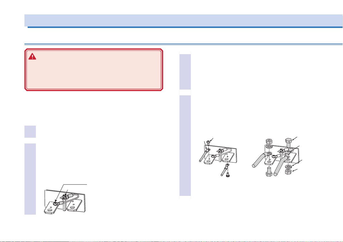
Connecting the Load
This M3 screw is fastened to the + (pos.)
Connection using M4 screws Connection using M8 screws
r
D
a
t
m
C
t
l
Connecting to the Output Terminal on the Rear Panel
WARNING
Possible electric shock. Be sure to turn the POWER
switch off before touching the output terminal on the
rear panel. Be sure to attach the OUTPUT terminal cover
after wiring the load.
The chassis connection wire is not included. If you are using the
chassis connection wire that comes with the analog remote control
connector kit (OP01-PAS), you can use it immediately as it is already assembled.
Turn the POWER switch off.
1
Connect the chassis terminal to either the - (neg.) or + (pos.)
2
output terminal using the chassis connection wire.
The output terminal has an M3 hole used to connect the
chassis connection wire. If you are not using the optional
OP01-PAS, attach a crimping terminal to a wire of AWG18
or higher to make the connection.
M3 screw
16 PWR Series Setup Guide
terminal before factory shipment. If you want
to connect the chassis connection wire to the
- (neg.) output terminal as shown in the
gure, change it as such.
Attach crimping terminals to the load wires.
3
The output terminal on the rear panel has M4- (with taps)
and M8-sized holes for connecting the load wires. Attach
the crimping terminal that matches the screws.
Use crimping terminals that are less than equal to 5.5 mm2
with the M4-sized holes.
Connect the load wire to the output terminal on the
4
rear panel.
If you are using M8 screws, pay attention to the direction of
the screws.
rimping
erminal
ttaching the load wire. Otherwise
he threads of the output terminal
M4 screw
o not fasten M4 screw without
ay be damaged.
If you do not connect the wire as
shown, the OUTPUT terminal cove
may hit the M8 screw.
M8 crew
Crimp termina
Spring
washer
Nut
Page 17
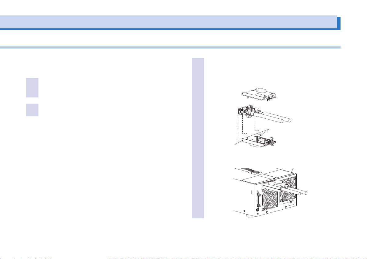
Attaching the OUTPUT terminal cover
Top cover
l
There are two types of OUTPUT terminal covers: bottom cover and
top cover.
Insert the hook of the bottom cover into the hole lo-
1
cated above and to the left of the output terminal.
The bottom cover is the one without screws.
Align the hook of the bottom cover to the groove lo-
2
cated to the side of the output terminal.
Align the bottom cover with the top cover, and fix
3
them in place using the screws attached to the top
cover.
Check that the screws are securely fastened.
Insert into the hole
in the rear panel
PWR Series Setup Guide 17
Align the protrusion on the inside
to the concavity of the output termina
Bottom cover
Align the top and bottom parts of the
terminal cover and screw them in place.
Page 18
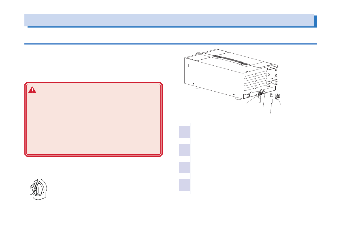
Connecting the Load (Cont.)
Connection to the Output Terminal on the Front Panel
The specifications of the PWR are defined for output terminal on the
rear panel. Those on the front panel may not satisfy the specifications.
Like the output terminal on the rear panel, the chassis terminal is
normally connected to either the - (neg.) or + (pos.) output terminal.
WARNING
• Possible electric shock. Be sure to turn the POWER
switch off before touching the output terminal on the
front panel.
Do not use the terminal with the front output terminal
cover removed. In addition, be sure to attach the OUTPUT terminal cover on the rear panel.
• Possible overheating or re. Do not supply currents
that exceed 30 A from the output terminal on the front
panel on the L type.
1
2
Attach so that the wire passes
through this section.
Turn the POWER switch off.
Attach crimping terminals to the load wires.
M6
Crimping terminal
Knob
If the front output terminal cover is damaged or lost, contact Kikusui distributor/agent.
[P1-000-408]
18 PWR Series Setup Guide
Remove the knob and connect the load wire to the out-
3
put terminal on the front panel.
Attach the knob.
4
Page 19

Trademarks
Microsoft, Windows, and Visual Basic are registered trademarks of
Microsoft Corporation in the United States and/or other countries.
All company names and product names used in the PWR manual
are trademarks or registered trademarks of their respective companies.
PWR Series Setup Guide 19
Page 20
环境保护使用期限
Environment-friendly Use Period
有毒有害物质或元素名称及含有标示
Name of hazardous materials and symbol of element in the equipment and quantity
该标记为适用于在中华人民共和国销售的电子信息产品的环境保护使
用期限。
只要遵守有关该产品的安全及使用注意事项,从制造年月起计算,在
该年度内,就不会对环境污染、人身、财产产生重大的影响。
产品的废弃请遵守有关规定。
产品的制造年月可以在以下网址中确认。
http://www.kikusui.co.jp/pi/
部件名称
Name of part
印刷电路板组装品
Printed circuit board
assemblies
内部接线
Internal wirings
外壳
Enclosure
底盘组装品
Chassis assembly
辅助设备
Accessories
本表格依据 SJ/T 11364
○ : 该部件所有均质材料的有毒有害物质的含量不超过 GB/T 26572 标准所规定
的极限值要求。
×: 该部件至少有一种均质材料的有毒有害物质的含量超过 GB/T 26572 标准所
规定的极限值要求。
有毒有害物质或元素
Hazardous material and symbol of element
铅
汞
镉Cd六价铬
Pb
Hg
× ○ × × ○ ○
× ○ × × ○ ○
× ○ × ○ ○ ○
× ○ × × ○ ○
× ○ ○ ○ ○ ○
的规定编制。
Cr(VI)
多溴联苯
PBB
多溴二苯醚
PBDE
20 PWR Series Setup Guide
 Loading...