

Kikusui PWR-01, PWR401ML, PWR401H, PWR401L, PWR801L Series Manual
...
Communication Interface Manual Regurated DC Power Supply PWR-01 Series
PART NO. IB031623
Apr. 2018
Communication Interface Manual
Regurated DC Power Supply PWR-01 Series
400W model
PWR401L PWR401MH
PWR401ML PWR401H
800W model
KIKUSUI ELECTRONICS CORP.
1-1-3 Higashiyamata, Tsuzuki-ku, Yokohama,
224-0023, Japan
Tel: +81-45-482-6353 Fax: +81-45-482-6261
Website
http://www.kikusui.co.jp/en
PWR801L PWR801MH
PWR801ML PWR801H
1200W model
PWR1201L PWR1201MH
PWR1201ML PWR1201H

Command List
Command List
*CLS
Clears all event registers including the status byte, event status, and error queue.
*ESE
Sets the event status enable register that is counted by the event summary bit (ESB) of the
status byte.
*ESR
Queries the event status register.
*IDN
Queries the model name, serial number, and rmware version of the PWR-01.
*LRN
Queries the command that can restore the current panel settings.
*OPC
Sets the OPC bit (bit 0) of the event status register when all the commands in standby have
been completed.
*OPT
Queries the option that are installed in the PWR-01.
*PSC
Sets whether to clear the event status enable register and the service request enable
register when the POWER switch is turned on (power-on status).
*RST
Resets the panel settings.
*SRE
Sets the service request enable register.
*STB
Queries the contents of the status byte register and the MSS (master summary status)
message.
*TRG
Trigger command.
*TST
Executes a self-test.
*WAI
Prevents the PWR-01 from executing subsequent commands until all operations in standby
are complete.
ABOR
Aborts operations such as change and execute sequence in all sequence groups.
ABOR:PROG
Aborts the sequence trigger function.
ABOR:TRAN
Aborts the setting change trigger function.
DISP:BRIG
Adjusts the screen brightness.
GLOB:*RST
Resets the panel settings (see *RST) of all the channels in the same multichannel domain.
GLOB:*TRG
Trigger command for all the channels in the same multichannel domain.
GLOB:ABOR
Aborts modifications and sequence execution on all trigger subsystems (TRANsient/
PROGram) of all the channels in the same multichannel domain.
GLOB:CURR
Sets the current of all the channels in the same multichannel domain.
GLOB:INIT:PROG
Starts the sequence trigger function of all the channels in the same multichannel domain.
GLOB:INIT:TRAN
Starts the setting change (TRANsient) trigger function of all the channels in the same
multichannel domain.
GLOB:OUTP
Turns the output on and off of all the channels in the same multichannel domain.
GLOB:OUTP:PROT:CLE
Clears alarms of all the channels in the same multichannel domain.
KIKUSUI Electronics Corp. PWR-01 Interface Manual

Command List
GLOB:VOLT
Sets the voltagee of all the channels in the same multichannel domain.
INIT:PROG
Starts the sequence trigger function.
INIT:TRAN
Starts the setting change (TRANsient) trigger function.
INST
Species the channel to congure.
INST:CAT
Queries the list of channels that can be congured with the INST command.
INST:INFO
Queries the information of the channel currently being controlled.
FETC:ALL/ MEAS:ALL
Queries the current and voltage.
FETC:CURR/ MEAS:CURR
Queries the measured value of the current.
FETC:VOLT/ MEAS:VOLT
Queries the measured value of the voltage.
OUTP:EXT
This is an old style command.
OUTP:EXT:ADV
Sets whether output will be turned on and off externally.
OUTP:EXT:LOG
Sets the logic used to control the turning of output on and off using an external contact.
OUTP:PON
Sets the output state at power-on.
OUTP:PROT:CLE
Clears alarms.
OUTP:PROT:WDOG
Sets the Communication monitor timer.
OUTP:TRIG:STAT
Sets whether to output a trigger signal when the output is turned on.
PROG:CRE
Deletes the existing program and creates a new program.
PROG:LOOP
Changes the number of times that the program will repeat.
MEM:REC
Recalls the voltage, current, OVP, UVL, and OCP values saved in the preset memory.
MEM:REC:PREV
Queries the settings that are stored in the preset memory.
MEM:SAVE
Saves the present voltage, current, OVP, UVL, and OCP values in the preset memory.
OUTP
Turns the output on and off.
PROG:REM:LOOP
Queries the number of repetitions remaining in the sequence that is running.
PROG:REM:TIME
Queries the time remaining in the sequence that is running.
PROG:STEPS
Queries the number of program steps.
PROG:STEPS:LOOP:ADD
Sets the starting step and ending step of an interval loop to execute in the program and the
number of interval loops.
OUTP:DEL:ON
Sets the output-on delay.
PROG:STEPS:LOOP:LIST
Queries all interval loops set in the program.
OUTP:DEL:OFF
Sets the output-off delay.
KIKUSUI Electronics Corp. PWR-01 Interface Manual
PROG:STEP<n>:CURR/ PROG:STEP_T:CURR
Sets the current and transition to use in the step.

Command List
PROG:STEP<n>:DWEL/ PROG:STEP_T:DWEL
Sets the step execution time.
PROG:STEP<n>:TRIGIN/ PROG:STEP_T:TRIGIN
Sets the step’s trigger signal input.
PROG:STEP<n>:TRIGOUT/ PROG:STEP_T:TRIGOUT
Sets the step’s trigger signal output.
PROG:STEP<n>:VOLT/ PROG:STEP_T:VOLT
Sets the voltage and transition to use in the step.
PROG:UCOD
Sets the user code to identify sequences.
CURR
Sets the current.
CURR:EXT:RANG
Sets the CC and CV control range that is used during external control.
CURR:EXT:SOUR
Sets whether constant current will be controlled externally.
CURR:LIM:AUTO
Enables or disables the limit on the current setting.
CURR:PROT
Sets the overcurrent protection (OCP) value.
CURR:PROT:DEL
Sets the detection time of OCP activation.
CURR:SST:FALL
Sets the soft stop time when the output is turned off.
CURR:SST:RISE
Sets the soft start time when the output is turned on.
CURR:TRIG
Sets the current value that is applied when a trigger is sent.
RES
Sets the internal resistance.
VOLT
Sets the voltage.
VOLT:EXT:RANG
Sets the CC and CV control range that is used during external control.
VOLT:EXT:SOUR
Sets whether constant voltage will be controlled externally.
VOLT:LIM:AUTO
Set whether to limit the voltage setting so that it does not exceed the OVP setting or
become lower than the UVP setting.
VOLT:LIM:LOW
Sets the undervoltage limit (UVL) trip point.
VOLT:PROT
Sets the overvoltage protection (OVP).
VOLT:SST:FALL
Sets the soft stop time when the output is turned off.
VOLT:SST:RISE
Sets the soft start time when the output is turned on.
VOLT:TRIG
Sets the voltage that is applied when a trigger is sent.
STAT:OPER
Queries the event of the OPERation status register.
STAT:OPER:COND
Queries the condition of the OPERation status register.
STAT:OPER:ENAB
Sets the enable register of the OPERation status register.
STAT:OPER:NTR
Sets the negative transition of the OPERation status register.
STAT:OPER:PTR
Sets the positive transition of the OPERation status register.
STAT:OPER:INST
Queries the event of the OPERation:INSTrument subregister.
KIKUSUI Electronics Corp. PWR-01 Interface Manual

Command List
STAT:OPER:INST:COND
Queries the condition of the OPERation:INSTrument subregister.
STAT:OPER:INST:ENAB
Sets the enable register of the OPERation:INSTrument subregister.
STAT:OPER:INST:NTR
Sets the negative transition of the OPERation:INSTrument subregister.
STAT:OPER:INST:PTR
Sets the positive transition of the OPERation:INSTrument subregister.
STAT:OPER:INST:ISUM<n>
Queries the event of the OPERation:INSTrument:ISUMmary<n> subregister.
STAT:OPER:INST:ISUM<n>:COND
Queries the condition of the OPERation:INSTrument:ISUMmary<n> subregister.
STAT:OPER:INST:ISUM<n>:ENAB
Sets the enable register of the OPERation:INSTrument:ISUMmary<n> subregister.
STAT:OPER:INST:ISUM<n>:NTR
Sets the negative transition of the OPERation:INSTrument:ISUMmary<n> subregister.
STAT:OPER:INST:ISUM<n>:PTR
Sets the positive transition of the OPERation:INSTrument:ISUMmary<n> subregister.
STAT:QUES:INST:COND
Queries the condition of the QUEStionable:INSTrument subregister.
STAT:QUES:INST:ENAB
Sets the enable register of the QUEStionable:INSTrument subregister.
STAT:QUES:INST:NTR
Sets the negative transition of the QUEStionable:INSTrument subregister.
STAT:QUES:INST:PTR
Sets the positive transition of the QUEStionable:INSTrument subregister.
STAT:QUES:INST:ISUM<n>
Queries the event of the QUEStionable:INSTrument:ISUMmary<n> subregister.
STAT:QUES:INST:ISUM<n>:COND
Queries the condition of the QUEStionable:INSTrument:ISUMmary<n> subregister.
STAT:QUES:INST:ISUM<n>:ENAB
Sets the enable register of the QUEStionable:INSTrument:ISUMmary<n> subregister.
STAT:QUES:INST:ISUM<n>:NTR
Sets the negative transition of the QUEStionable:INSTrument:ISUMmary<n> subregister.
STAT:QUES:INST:ISUM<n>:PTR
Sets the positive transition of the QUEStionable:INSTrument:ISUMmary<n> subregister.
STAT:QUES
Queries the event of the QUEStionable status register.
STAT:QUES:COND
Queries the condition of the QUEStionable status register.
STAT:PRES
Resets the ENABle, PTRansition, and NTRansition filter registers of all status registers
(including sub registers) to their default values. 32 bits registers are used by the
multichannel function.
SYST:BEEP:STAT
STAT:QUES:ENAB
Sets the enable register of the QUEStionable status register.
Turns the buzzer on and off.
SYST:COMM:RLST
STAT:QUES:NTR
Sets the negative transition of the QUEStionable status register.
Sets the operation of the PWR-01 to local or remote.
SYST:CONF:BLE
STAT:QUES:PTR
Sets the positive transition of the QUEStionable status register.
Sets the bleeder circuit operation.
SYST:CONF:MAST
STAT:QUES:INST
Queries the event of the QUEStionable:INSTrument subregister.
KIKUSUI Electronics Corp. PWR-01 Interface Manual
Queries the number of units in master-slave parallel operation.

Command List
SYST:CONF:MON:RANG
Sets the range for monitoring the voltage or current externally.
SYST:CONF:PROT:REC
Sets the output state when a low AC input protection (AC-FAIL) is released.
SYST:CONF:SC1/ SYST:CONF:SC2/ SYST:CONF:SC3
Registers the CONFIG setting item to the panel’s SC key.
SYST:CONF:SLAV:AMM
Sets whether or not the current or power on slave units is displayed on the panel during
master-slave parallel operation.
SYST:CONF:STAR:PRI
Sets the operation mode to be prioritized when the output is turned on.
SYST:ERR
Reads the oldest error information or event information from the error queue. The error
queue can store up to 16 errors.
-> Tutorial “Error Checking”
SYST:ERR:COUN
Returns the number of unread errors in the error queue.
SYST:ERR:TRAC
Sets whether to display communication errors by performing a debug trace.
SYST:EXT:STATOUT:CC:POL
Sets the polarity of the status output signal for constant-current mode.
SYST:EXT:STATOUT:CV:POL
Sets the polarity of the status output signal for constant-voltage mode.
SYST:KLOC
Sets and releases the panel operation lock (keylock).
SYST:LOC/ SYST:REM/ SYST:RWL
This is an old style command.
SYST:SEC:IMM
Sanitizes all contents stored in memory and initializes the panel settings to their factory
default conditions.
SYST:VERS
Queries the version of the SCPI specications to which the PWR-01 conforms.
TRIG:PROG
Executes a software trigger for the PROGram trigger subsystem.
TRIG:PROG:EXEC
Queries the sequence states (execution state, present repetition count, present step
number, elapsed time, estimated time).
TRIG:PROG:SOUR
Sets the condition (trigger source) that determines when the PROGram trigger subsystem
actually executes a sequence operation after the PWR-01 receives the INIT:PROG
command.
TRIG:TRAN
Executes a software trigger for the TRANsient trigger subsystem.
TRIG:TRAN:SOUR
Sets the condition (trigger source) that determines when the TRANsient trigger subsystem
actually changing the setting after the PWR-01 receives the INIT:TRAN command.
SYST:EXT:STATOUT:OUTP:POL
Sets the polarity of the status output signal for output.
SYST:EXT:STATOUT:PROT:POL
Sets the polarity of the status output signal for protection operation.
SYST:EXT:TRIGIN:POL
Sets the polarity of the trigger signal input.
SYST:EXT:TRIGOUT:POL
Sets the polarity of the trigger signal output.
KIKUSUI Electronics Corp. PWR-01 Interface Manual

Introduction
Introduction
The PWR-01 series Communication Interface Manual explains the settings and
commands for remotely controlling the PWR-01 series.
• RS232C interface
• USB interface
• LAN interface
When the PWR-01 series is operating under remote control, the RMT LED on the
display on the front panel lights. To switch from remote mode to local mode from
the panel, press LOCAL.
For the safety precautions, installation, operation, and specications of the PWR01, read the accompanying PWR-01 series User's Manual.
■ Reading environment
This manual is in PDF format. The manual can be viewed by the following environ-
ment.
PDF Reader: Adobe Reader
■ Intended readers
This manual is written for readers with sufcient basic knowledge of how to control
instruments using a PC.
Familiarize yourself with the syntax of the SCPI commands that are used with the
product before you use them.
■ Structure of the manual
This manual consists of the following sections.
• Overview
• Setup
• Overview of messages
• Command
• Appendix
• Tutorial
■ Trademarks
Microsoft and Windows are registered trademarks of Microsoft Corporation in the
United States and/or other countries.
All other company names and product names used in this manual are trademarks
or registered trademarks of the respective company.
■ Firmware version of the product to which this manual applies
This manual applies to products with the following rmware version:
Ver.1.1x
KIKUSUI Electronics Corp. PWR-01 Interface Manual

Interface Setup
■ Instrument Interface Standards
The PWR-01 conforms to the following standards.
• IEEE Std 488.2-1992 IEEE Standard Codes, Formats, Protocols, and Common
Commands For Use With IEEE Std 488.1-1987
• IEEE Std 488.1-1987 IEEE Standard Digital Interface for Programmable Instru-
mentation
• Standard Commands for Programmable Instruments (SCPI) version 1999.0
• Universal Serial Bus Specication Rev 2.0
• Universal Serial Bus Test and Measurement Class Specication (USBTMC) Rev
1.0
• Universal Serial Bus Test and Measurement Class, Subclass USB488 Specication (USBTMC-USB488) Rev 1.0
• TCP/IP Instrument Protcol Specication VXI-11 Rev 1.0 1995
• TCP/IP-IEEE488.2 Interface Specication VXI-11.3 Draft 0.3 1995
• LXI Device Specication 2011 rev 1.4
• LXI HiSLIP Extended Function Rev 1.01
• IVI-6.1 IVI High-Speed LAN Instrument Protocol (HiSLIP) Rev 1.0
• VPP-4.3 The VISA Library 2015 Rev 5.5
■ Copyright and publication
Interface Setup
Installing the VISA Library
VISA (Virtual Instrument Software Architecture) is a specication for standard software that is used to connect instruments. VISA was dened by the IVI Foundation.
A VISA library is required to use the software application. The VISA library (NI-VISA,
Keysight VISA, or KI-VISA) must be installed on the controller (Windows).
One of the VISA libraries (driver software implemented in compliance with the VISA
specications) below is necessary.
• NI-VISA by National Instruments (Ver. 5.1.1 or later)
• Keysight VISA by Keysight Technologies (Keysight IO Libraries Suite16.0 or later)
• KI-VISA Ver. 5.0.4 or later
- Note If your VISA library is an older version than that specied, you may not be able to
use it depending on the interface.
The contents of this manual may not be reproduced, in whole or in part, without the
prior consent of the copyright holder.
The specications of this product and the contents of this manual are subject to
change without prior notice.
Copyright 2017 Kikusui Electronics Corp.
KIKUSUI Electronics Corp. PWR-01 Interface Manual

Interface Setup
■ Installing KI-VISA
- Note Do not install multiple VISA libraries on the same PC. Doing so may cause errors.
KI-VISA is not required if NI-VISA or Keysight VISA is already installed.
KI-VISA is Kikusui's original VISA library that supports the VXIplug&play VISA specications.
The newest version can be downloaded from the Kikusui website (http://www.kikusui.co.jp/en/download/).
When you install the VISA library, the following tools will be installed.
• KI-VISA Instrument Explorer
Communication interface environment conguration (IO Cong) tool
• IVI Conguration Utility
IVI measuring instrument driver’s virtual measuring instrument and measuring
instrument session conguration tool
• KI-VISA SPY
Debug support tool
Installation requires administrator privileges.
Load the accompanying CD-ROM into the CD-ROM drive.
1
Move to the VISA folder using the top window of the CD-ROM or Ex-
2
plorer.
Interface Setup
The PWR-01 is equipped with LAN, RS232C, and USB interfaces as standard.
There is no need to switch interfaces. All interfaces can be used simultaneously.
LAN Interface can be set to OFF in CONFIG settings.
RS232C
USB
LAN
Accessing and Operating the PWR-01 from a Web Browser (LAN interface)
Double-click Kivisa_x_x_x.exe.
3
The VISA library is available in a 32-bit version (x86) and 64-bit version (x64).
The value for x varies depending on the revision of the VISA library stored on the
CD-ROM.
Proceed with the installation according to the instructions on the
4
screen.
If an old KI-VISA is installed, it will be uninstalled. With the x64 version, when the
KI-VISA installation is completed, the installation of WOW 64-bit version will begin. Be sure to also install WOW 64-bit version.
KIKUSUI Electronics Corp. PWR-01 Interface Manual
Interface Setup
[P1-000-131]
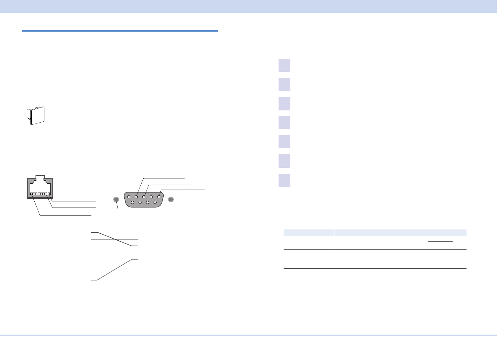
RJ-45-DB9 adapter cable
D-sub 9pin male
RS232C
■ RS232C connection
This product’s RS232C/TRIG IN connector (RS232C connector) is RJ-45. Check
that the PWR-01 and your PC are off before connecting them.
The RS232C port of this product comes with a cover. Remove the cover to use the
port. Store the cover in a safe place so that you can use it to cover the RS232C
port when the port is no longer in use. For safety reasons, when not using the
RS232C port, be sure to attach to cover. For safety reasons, when not using the
sensing terminals, be sure to attach to terminal cover.
Port cover
The PWR-01 LAN port is the same shape as a RS232C port. Check the connector
name marked on the rear panel to identify the appropriate one to use.
The optional RJ-45 - DB9 adapter cable can be used to connect the PWR-01 to a
PC.
RJ-45 male
2:RXD (receive data)
3:TXD (transmit data)
5:GND (signal ground)
■ RS232C conguration
The factory default RS232C settings are RS232C enabled and 19 200 bps bau-
drate.
For datails of CONFIG settings, see the PWR-01 user's manual.
Press CONFIG several times until CF40 is displayed.
1
Turn the VOLTAGE knob until CF42 (RS232C interface setting) is dis-
2
played.
Use the CURRENT knob to select ON.
3
RS232C is enabled.
Press CONFIG several times until CF70 is displayed.
4
Turn the VOLTAGE knob until CF72 (RS232C interface data rate setting)
5
is displayed.
Use the CURRENT knob to set the baudrate.
6
For the settings, see the table under Protocol below.
Restart the PWR-01.
7
The settings are applied.
1:RXD (receive data)
2:TXD (transmit data)
8:GND (signal ground)
#4-40UNC
inch screw
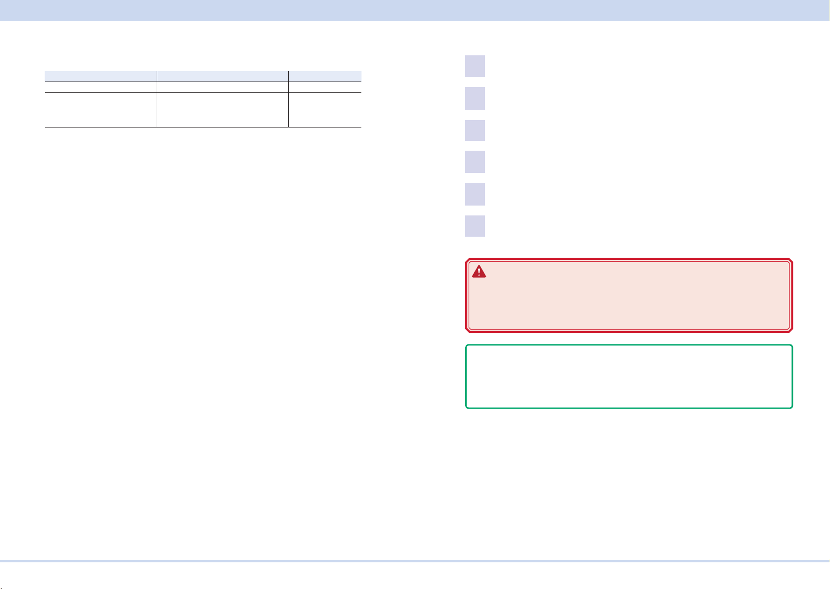
■ Protocol
The following table shows the settings that correspond to the RS232C protocol.
Underlined values are factory default settings.
1
2
3
4
5
6
7
8
RJ-45 female
1
2
3
4
5
6
7
8
9
D-sub 9-pin female
Item Setting
Baudrate 1 200 bps/ 2 400 bps/ 4 800 bps/ 9 600 bps/ 19 200 bps/
38 400 bps/ 57 600 bps/ 115 200 bps
Data Fixed to 8 bit
Stop Fixed to 1 bit
Flow (X-ow control) Fixed to None
TRIG-IN is assigned to pin 7 of the this product’s RS232C connector. TRIG-IN is
used for synchronized operation.
KIKUSUI Electronics Corp. PWR-01 Interface Manual

Interface Setup
[P1-000-132]
■ RS232C communication
The PWR-01 does not have ow control (this is xed). If you send setting commands consecutively at a high speed, the PWR-01 reception buffer may overow.
Do not send setting commands consecutively. Send query commands and read the
responses at a certain interval, or reduce the command transmission frequency.
■ Break signal
The break signal functions as a substitute for the IEEE488.1 dcl / sdc (Device
Clear, Selected Device Clear) message.
- Note The RS232C interface should be shifted remotely by the command. Use the
"SYST:COMM:RLST" SCPI command to set the RS232C interface to the remote
state. Be sure to include this command at the start of the program when you are
performing remote programming.
USB
A device driver supporting USB T&M Class (USBTMC) is required to control the
PWR-01 through the USB interface. The USBTMC driver is automatically installed
by the VISA library.
■ USB connection
Use a standard USB cable to connect the PWR-01 to the PC.
The USB port of this product comes with a cover. Remove the cover to use the
port. Store the cover in a safe place so that you can use it to cover the USB port
when the port is no longer in use. For safety reasons, when not using the USB port,
be sure to attach to cover. For safety reasons, when not using the sensing termi-
nals, be sure to attach to terminal cover.
Port cover
■ USB setting
The factory default USB setting is “USB enabled.”
For datails of CONFIG settings, see the PWR-01 user's manual.
Press CONFIG several times until CF40 is displayed.
1
Turn the VOLTAGE knob until CF41 (USB interface setting) is displayed.
2
Use the CURRENT knob to select ON.
3
USB is enabled.
Restart the PWR-01.
4
The settings are applied.
■ Service request
The PWR-01 is equipped with service request and serial polling functions.
KIKUSUI Electronics Corp. PWR-01 Interface Manual

Interface Setup
[P1-000-131]
■ USB function
Complies with USB Specication 2.0
Complies with USBTMC Specication 1.0 and USBTMC-USB488 Specication 1.0
Data rate: 480 Mbps maximum (High speed)
VID (Vender ID)
0x0B3E
PID (Product ID)
PWR-01 400W model: 0x1049
PWR-01 800W model: 0x104A
PWR-01 1200W model: 0x104B
LAN
WARNING
If a network problem occurs, an unexpected dangerous voltage may oc-
cur that may cause electric shock, re, physical damage to the DUT, and
so on. If you are going to remotely control the PWR-01 from a distance,
install a Web camera or take other measures to monitor the status.
To use the LAN interface to control the PWR-01, middleware that supports the SCPI-Telnet/ VXI-11/ HiSLIP/ SCPI-RAW protocol must be installed on the controller.
The middleware is installed automatically by the VISA library.
There is a Web browser interface to the PWR-01 embedded in the LAN interface
board. You can congure the LAN interface settings from your PC's Web browser.
For information on topics such as connecting to your corporate LAN, your IP address, your host name, and security, contact your network administrator.
If you are using a host name (a Bonjour host name), you have to install Apple Bon-
jour.
■ LAN connection
Use a standard LAN cable (category 5 and straight) to connect the PWR-01 to a
network hub or router. Use a crossover cable when making a direct connection.
The LAN port of this product comes with a cover. Remove the cover to use the port.
Store the cover in a safe place so that you can use it to cover the LAN port when
the port is no longer in use. For safety reasons, when not using the LAN port, be
sure to attach to cover. For safety reasons, when not using the sensing terminals,
be sure to attach to terminal cover.
Port cover
The PWR-01 RS232C port is the same shape as a LAN port. Check the port name
marked on the rear panel to identify the appropriate one to use.
KIKUSUI Electronics Corp. PWR-01 Interface Manual
Interface Setup
■ LAN setting
For normal use, we recommend using the factory default settings.
Setting Description (Factory default setting) CONFIG setting
LAN setting Use LAN CF40: ON
IP address allocation method DHCP: on
AUTO IP: on
MANUAL IP: off
When connecting directly, for the IP address allocation method, set DHCP to off,
Auto-IP to on, and MANUAL to off (CF61: 010) to automatically set the IP address.
To set the IP address manually, for the IP address allocation method, set DHCP
to off, Auto-IP to off, MANUAL to on (CF61: 001), and set the IP address (CF62 to
CF65).
If you change the interface settings (CF61 to CF66), apply the changes (CF60:
APPL) or restart the power supply to make the new settings take effect.
CF61: 110
For datails of CONFIG settings, see the PWR-01 user's manual.
Press CONFIG several times until CF40 (LAN interface setting) is dis-
1
played.
Use the CURRENT knob to select ON.
2
LAN is enabled.
Press CONFIG several times until CF60 is displayed.
3
Turn the VOLTAGE knob until CF61 (IP address assignment method) is
4
displayed.
Use the CURRENT knob to set 110.
5
DHCP and AUTO IP are set to on, and MANUAL IP is set to off.
Turn the POWER switch off and then back on to enable the settings.
6
WARNING
Possible damage to the equipment and electric shock. The LAN interface
can be accessed from any place on the network. If necessary, congure
the security settings. You can apply password protection for security, and
you can restrict the IP addresses to limit the hosts.
- Note The LAN interface should be shifted remotely by the command. Use the "SYS-
T:COMM:RLST" SCPI command to set the RS232C interface to the remote state.
Be sure to include this command at the start of the program when you are per-
forming remote programming.
■ Service request
The PWR-01 is equipped with service request and serial polling functions.
KIKUSUI Electronics Corp. PWR-01 Interface Manual

Interface Setup
■ LAN function
The PWR-01 may require an Internet connection depending on the how the PWR01 is accessed through a Web browser.
Complies with the LXI 1.4 Core 2011
Complies with the SCPI-Telnet/ VXI-11/ HiSLIP/ SCPI-RAW protocol
Communication speed: Maximum 100 Mbps (Auto negotiation)
AUTO MDIX function
Web browser access
Instrument information, network information, display of VISA resource information, checking the connected PWR-01, remote control from browser, changing
network settings, system status information, license information, password set-
ting
■ Restarting the LAN interface (APPL)
You can use the CONFIG settings to restart the LAN interface (CF60: APPL). However, the setting condition of LAN interface will not be changed.
This operation does not affect the PWR-01's panel settings.
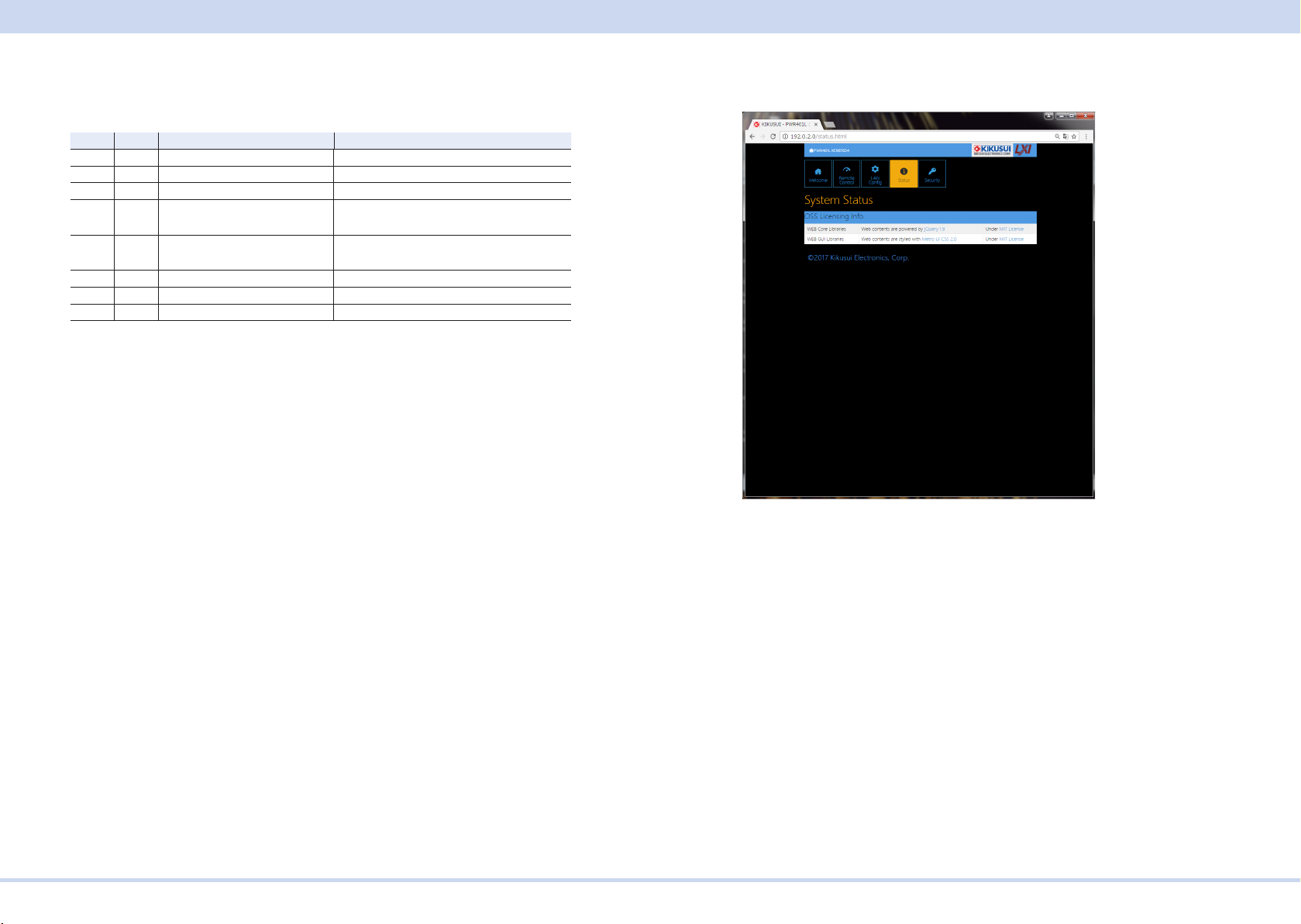
■ Resetting the LAN interface (LCI/ DEF)
You can use the CONFIG settings to reset the LAN interface (CF60: LCI/ DEF).
When reset, network settings are changed as follows.
The items with an X mark are returned to their default values.
Accessing and Operating the PWR-01 from a Web Browser (LAN interface)
You can use the LAN interface to congure detailed settings from a Web browser
on your PC. Use latest version of browser.
The Web site's URL is dened by adding "http://" in front of the PWR-01's IP ad-
dress.
You can enter the URL directly in the address bar of your Web browser by using
the CONFIG settings (CF50 to CF53) to view the IP address.
When you are using a VISA library, a function is available that enables the application program (such as National Instruments NI-MAX, Keysight Connection Expert,
and Kikusui KI-VISA Instrument Explorer) to retrieve the VXI-11 measuring instrument. This function is provided by VISA vendors. You can access the PWR-01 by
clicking on the hyperlink that is provided in the retrieval results.
CONFIG Display Description
CF50 0 to 255 Display the 1st number of the IP address
CF51 0 to 255 Display the 2nd number of the IP address
CF52 0 to 255 Display the 3rd number of the IP address
CF53 0 to 255 Display the 4th number of the IP address
(Example) When the IP address is 169.254.7.8
http://169.254.7.8
LCI DEF Item Default Value
X X Assignment Method DHCP:ON, Auto-IP:ON, Static:OFF
X DNS Server Assignment 0.0.0.0
X WINS Server Assignment 0.0.0.0
X Desired Hostname <Model name> - <Last 5 digits of serial
number>
X Desired Description KIKUSUI <Model name> Electronic
Load - <Serial number>
X X Enable Dynamic DNS Enable
X X Enable mDNS Enable
X X Enable NetBIOS Over TCP/IP Enable
X X Password Security Not set
X VMCB Setting 0
KIKUSUI Electronics Corp. PWR-01 Interface Manual
Interface Setup
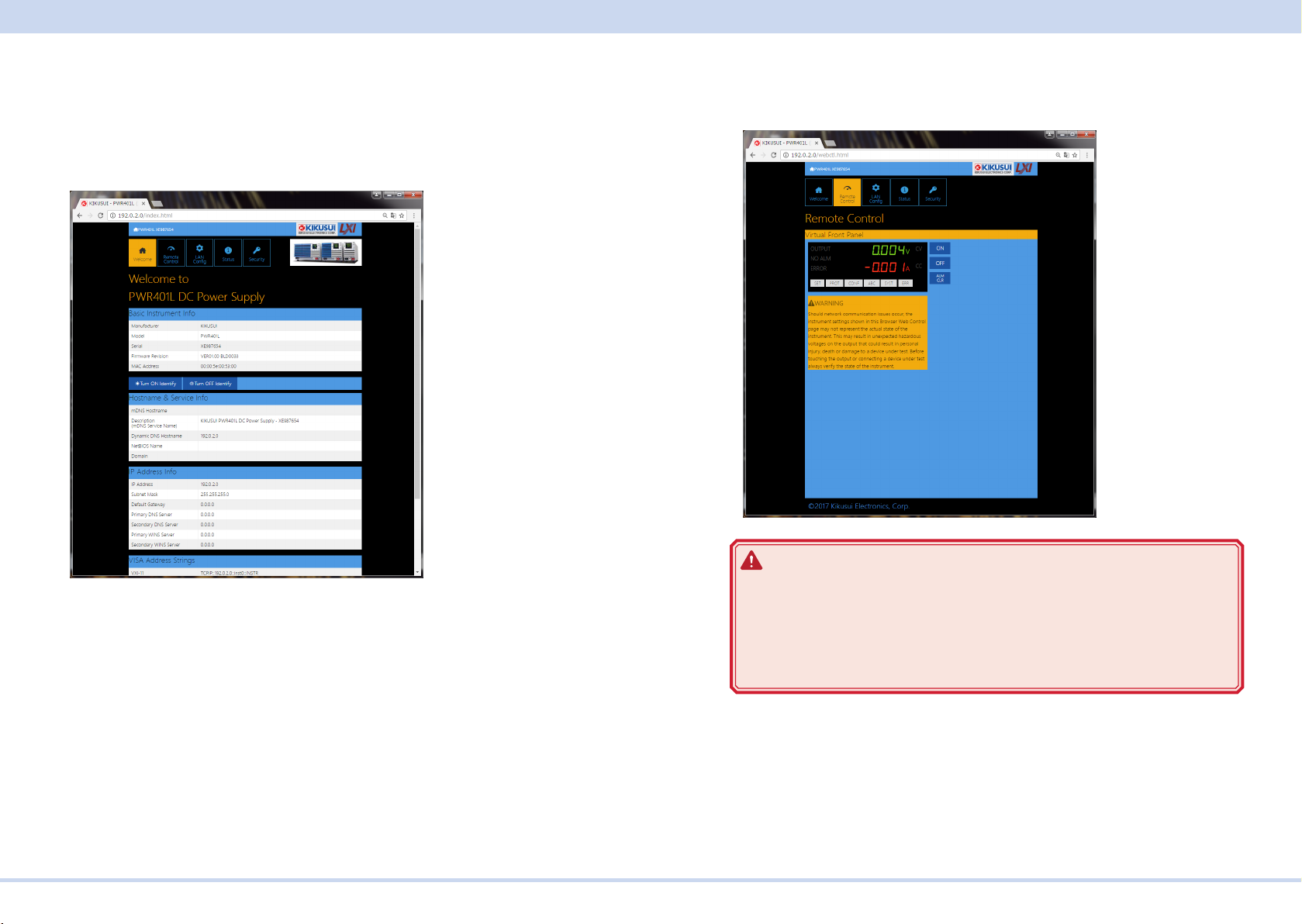
■ WELCOME page
When you access the PWR-01 from a Web browser, the WELCOME page is displayed rst.
The instrument information, network information, and VISA resource (I/O resource)
information appear on the display. Click items in the navigation menu to move to
the other pages.
■ Remote Control page
You can remotely control the PWR-01 from a browser. The various buttons have
the same functions as those on the front panel of the PWR-01.
WARNING
Should network communication issues occur, the instrument settings
Turn ON Identify: The LAN LED on the front panel of the connected PWR-01 blinks
so that you can identify it.
Turn OFF Identify: The LAN LED blinking stops.
shown in this Browser Web Control page may not represent the actual
state of the instrument. This may result in unexpected hazardous voltages on the output that could result in personal injury, death or damage to
a device under test. Before touching the output or connecting a device
under test always verify the state of the istrument.
KIKUSUI Electronics Corp. PWR-01 Interface Manual

Interface Setup
■ LAN Cong page
You can display (VIew Mode) and change (Modify Mode) the network settings.
Navigation (View Mode)
Modify Now: Goes to the network setting item editing screen (Modify Mode).
IP Address Assignment
You can set the IP address You can choose between automatic assignment and
assignment of a xed address.
In the case of automatic assignment of IP address, we recommend using the DHCP
server function using a router as far as possible.
If the DHCP server function is not used, it takes about 60 seconds until determination that address assignment with DHCP has failed. Then, an address between
169.254.0.0 to 169.254.255.255 is assigned by link local address (Auto-IP).
DNS Server Assignment
Sets the address of the DNS server.
WINS Server Assignment
Sets the address of the WINS server.
Hostname & Services
You can set the host name and so on. If you set the host name, you can use it in
place of the IP address to access the LAN interface. Normally, we recommend that
you select “Enable Dynamic DNS”, “Enable mDNS”, and “Enable NetBIOS Over
TCP/IP”.
If you leave the Hostname and Description boxes empty and click “Apply,” the host
name will be created from the model name and serial number.
TCP Ports (View Mode)
The number of the TCP port in use is displayed. You cannot change the port num-
ber.
Navigation (Modify Mode)
Undo: Returns the edited contents to the state before editing.
Apply: Applies the edited contents.
Reset: Resets the network settings.
Default: Returns the network settings to the factory default settings.
Back to View Mode: Goes to the network setting item viewing screen (View Mode).
KIKUSUI Electronics Corp. PWR-01 Interface Manual
Interface Setup
Reset and factory default settings
Clicking Reset and Default changes the network settings change as follows.
The items with an X mark are returned to their default values.
Reset Default Item Default Value
X X Assignment Method DHCP:ON, Auto-IP:ON, Static:OFF
X X DNS Server Assignment 0.0.0.0
X X WINS Server Assignment 0.0.0.0
X Desired Hostname <Model name> - <Last 5 digits of serial
number>
X Desired Description KIKUSUI <Model name> Electronic Load -
<Serial number>
X X Enable Dynamic DNS Enable
X X Enable mDNS Enable
X X Enable NetBIOS Over TCP/IP Enable
■ Status page
Displays the license information of the open-source software.
KIKUSUI Electronics Corp. PWR-01 Interface Manual
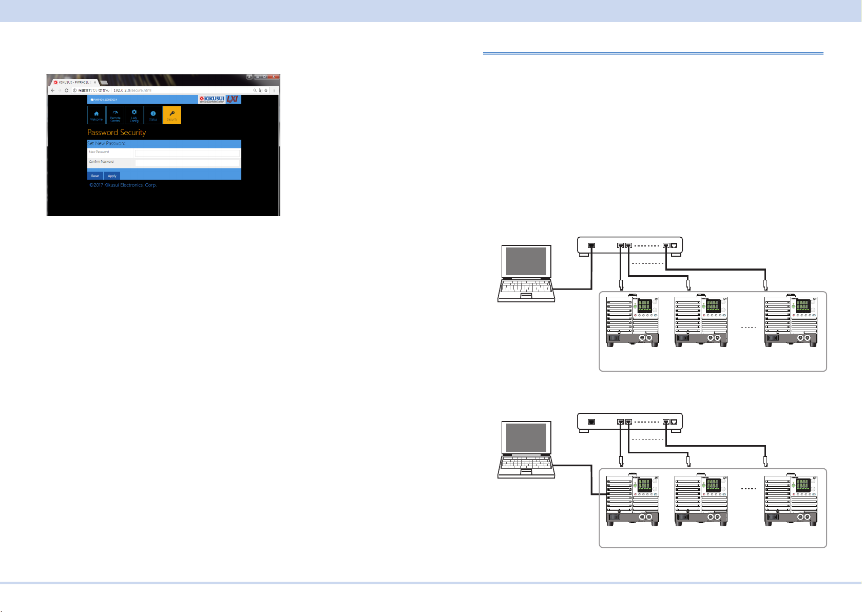
Interface Setup
When the master unit is connected to the PC through the LAN interface
When the master unit is connected to the PC through the RS232C or USB interface
Same domain number
■ Security page
You can set and change the password for the Web browser interface here.
When a password has been set, that password is required in order to use the following functions.
Remote control from Remote Control page
Editing of LAN Conguration page
Changing/deleting the password
Set New Password
Enter the password.
You can use alphanumeric characters, hyphens, and underscores for the password.
15 characters maximum. The rst character should be an alphabetical character.
The maximum password length is 15 characters.
Changing/deleting the password
After the password has been set, the screen for changing the password appears
when you enter the password.
To change the password, enter the present password in “Current Password”, enter
the new password in “New Password”and “Conrm Password”, and then click “Apply”.
To disable password protection, enter the present password in “Current Password”,
leave “New Password”and “Conrm Password” blank, and click “Apply”.
If you forget the password
If you forget the password, reset the LAN interface setting in the CONFIG settings
(CF60: LCI/DEF) or initialize the PWR-01 to its factory default settings.
For datails of CONFIG settings, see the PWR-01 user's manual.
Multichannel Setup
If you use the multichannel (VMCB) function, you can connect one PC to up to 31
PWR-01s to construct a virtual multichannel power supply system. This is useful
when you want to synchronize the operation of multiple PWR-01s or minimize the
number of communication ports that are required.
■ Multichannel connections
Set one PWR-01 as the master unit (VMCB master unit), and then connect this
PWR-01 to the PC through the LAN, RS232C, or USB interface. The other PWR01s are slave units (VMCB slave units). Use a switching hub or broadband router to
connect the slave units to the master unit through the LAN interface. Use standard
LAN cables (category 5).
Switching hub or broadband router
To a LAN
PC
PC
Port
Straight
cable
Switching hub or broadband router
To an RS232C
connector
or a USB port
To a LAN port
REGULATED DC POWER SUPPLY
CV
CV
OUTPUT
V
V
VOLTAGE
CC
CC
A
A
CURRENT
/
W
/
W
DLY SEQ HBSSVIR
ALM RMT LOCK LAN
ALM RMT LOCK LAN
B CAPRESET
CONFIG
PWR DSPMEMORY
LOCALSET OCPOVP
SHIFT
SC2 SC3 LOCKALM CLR SC1
PWR
POWER
MAX10A
DC OUTPUT
VMCB master unit
Channel 0
To a LAN port
REGULATED DC POWER SUPPLY
CV
CV
OUTPUT
V
V
VOLTAGE
CC
CC
A
A
CURRENT
/
W
/
W
DLY SEQ HBSSVIR
ALM RMT LOCK LAN
ALM RMT LOCK LAN
B CAPRESET
CONFIG
PWR DSPMEMORY
LOCALSET OCPOVP
SHIFT
SC2 SC3 LOCKALM CLR SC1
PWR
POWER
MAX10A
DC OUTPUT
VMCB master unit
Channel 0
FINE
FINE
POWER
VMCB slave unit
Channel 1
FINE
FINE
POWER
VMCB slave unit
Channel 1
REGULATED DC POWER SUPPLY
CV
CV
OUTPUT
V
V
FINE
VOLTAGE
CC
CC
A
A
CURRENT
/
W
/
W
FINE
DLY SEQ HBSSVIR
ALM RMT LOCK LAN
ALM RMT LOCK LAN
B CAPRESET
CONFIG
PWR DSPMEMORY
LOCALSET OCPOVP
SHIFT
SC2 SC3 LOCKALM CLR SC1
PWR
MAX10A
DC OUTPUT
REGULATED DC POWER SUPPLY
CV
CV
OUTPUT
V
V
FINE
VOLTAGE
CC
CC
A
A
CURRENT
/
W
/
W
FINE
DLY SEQ HBSSVIR
ALM RMT LOCK LAN
ALM RMT LOCK LAN
B CAPRESET
CONFIG
PWR DSPMEMORY
LOCALSET OCPOVP
SHIFT
SC2 SC3 LOCKALM CLR SC1
PWR
POWER
MAX10A
DC OUTPUT
VMCB slave unit
Channel 30
Same domain number
REGULATED DC POWER SUPPLY
CV
CV
OUTPUT
V
V
FINE
VOLTAGE
CC
CC
A
A
CURRENT
/
W
/
W
FINE
DLY SEQ HBSSVIR
ALM RMT LOCK LAN
ALM RMT LOCK LAN
B CAPRESET
CONFIG
PWR DSPMEMORY
LOCALSET OCPOVP
SHIFT
SC2 SC3 LOCKALM CLR SC1
PWR
MAX10A
DC OUTPUT
REGULATED DC POWER SUPPLY
CV
CV
OUTPUT
V
V
FINE
VOLTAGE
CC
CC
A
A
CURRENT
/
W
/
W
FINE
DLY SEQ HBSSVIR
ALM RMT LOCK LAN
ALM RMT LOCK LAN
B CAPRESET
CONFIG
PWR DSPMEMORY
LOCALSET OCPOVP
SHIFT
SC2 SC3 LOCKALM CLR SC1
PWR
POWER
MAX10A
DC OUTPUT
VMCB slave unit
Channel 30
KIKUSUI Electronics Corp. PWR-01 Interface Manual

Interface Setup
■ Multichannel settings
On the master unit, congure the settings for the connection with the PC, and set
the channel and domain.
On the slave units, congure the LAN settings, and set the channels and domains.
PWR-01s that have the same domain number perform multichannel operations
as a single VMCB network. You can connect up to 31 PWR-01s to a single VMCB
network.
Multichannel uses Multicast DNS (mDNS). Under Hostname / Service on the LAN
CONFIG page accessed through a Web browser, the Enable mDNS check box
must be selected. By default, this check box is selected.
For datails of CONFIG settings, see the PWR-01 user's manual.
- Note -
• Within the VMCB network, channel 0 is assigned to the master unit and all other
channel numbers are assigned to slave units. Do not assign the same channel
to two different PWR-01s on the same VMCB network.
• Congure all PWR-01s so that they have the same LAN settings (CF61: IP
address assignment method, CF67: VMCB domain number).
Slave unit settings
Normally, you should set DHCP and AUTO IP to ON to set the IP address automatically. For details on the LAN settings, see LAN under Interface Setup.
Congure all PWR-01s on the same VMCB network so that they have the same
CONFIG settings (CF61: IP address assignment method, CF67: VMCB domain
number).
The remote interface setting (CF40) is not valid on slave units.
Press CONFIG several times until CF60 is displayed.
1
Turn the VOLTAGE knob until CF61 (IP address assignment method) is
2
displayed.
Use the CURRENT knob to select 110.
3
DHCP and AUTO IP are set to on, and MANUAL IP is set to off.
If you do not want to use a DHCP server or the AUTO IP function, refer to the user’s manual and set them accordingly.
Turn the VOLTAGE knob until CF67 (multichannel (VMCB) domain num-
4
ber) is displayed.
Use the CURRENT knob to set the domain number.
5
PWR-01s that have the same domain number perform multichannel operations.
Set this value to a number other than 0.
Turn the VOLTAGE knob until CF68 (multichannel (VMCB) channel
6
number) is displayed.
Use the CURRENT knob to set the channel number.
7
Specify a unique channel number on the VMCB network. For a slave unit, set
this value to a number other than 0.
Turn the PWR-01 off.
8
KIKUSUI Electronics Corp. PWR-01 Interface Manual

Interface Setup
Master unit settings
Congure the settings for the connection with the PC.
1
For details on settings for the connection with the PC, see Interface Setup.
Press CONFIG several times until CF60 is displayed.
2
Turn the VOLTAGE knob until CF67 (multichannel (VMCB) domain num-
3
ber) is displayed.
Use the CURRENT knob to set the domain number.
4
PWR-01s that have the same domain number perform multichannel operations.
Set this value to a number other than 0.
Turn the VOLTAGE knob until CF68 (multichannel (VMCB) channel
5
number) is displayed.
Use the CURRENT knob to select 0.
6
Because this is the master unit, set this value to 0.
Turn the PWR-01 off.
7
Caution
The LAN interface can be accessed from any place on the network. If necessary,
congure the security settings. You can apply password protection for security,
and you can restrict the IP addresses to limit the hosts.
Turning power on
First turn the slave units on, and then turn the master unit on. If the PWR-01s are
organized in a rack system, turn all the units on at the same time. If you turn the
master unit on rst, the slave units will not be detected correctly.
When a slave unit turns on, all its LEDs light, and then the following sequence is
displayed: the rated voltage and rated current, the rmware version number, and
then the build number. Each item is displayed for approximately 1 second. Then,
the slave unit displays "I-F SLAV" and enters the wait state. When the PWR-01 is
designated as a slave unit by the master unit, the slave unit enters the operation
wait state.
The slave unit will not stop displaying "I-F SLAV" until it receives the slave designation from the master unit. Check the CONFIG parameters (CF61, CF67, and CF68)
and the LAN connection. If you change the CONFIG parameters, reboot the PWR-
01.
When the master unit turns on, all its LEDs light, and then the following sequence
is displayed: the rated voltage and rated current, the rmware version number, and
then the build number. Each item is displayed for approximately 1 second. Then,
the master unit displays "FIND CH" and searches for slave units. When the master
unit nishes searching, it enters the operation wait state.
Checking the multichannel conguration
To check the multichannel conguration, send the INSTrument:CATalog? query.
You cannot check the conguration from the panel.
KIKUSUI Electronics Corp. PWR-01 Interface Manual

Overview of Command
Overview of Command
The information that is exchanged between the controller (PC) and the device
(PWR-01 series) is called a message.
The PWR-01 uses the SCPI language for the messages.
There are two types of messages, commands that are sent from the PC to the
PWR-01 and responses that are sent from the PWR-01 to the PC.
Command Hierarchy
SCPI commands are ASCII-based commands designed for test and measurement
devices. The command hierarchy is structured around the common root or node,
which is the construction block of the SCPI subsystem. A command consists of a
program header, parameters, and punctuation.
The hierarchy is explained using the SOURce subsystem as an example.
Program header Parameter Hierarchy of node
SOUR: Root node
CURR Second level
:LIM Third level
:AUTO <boolean> Fourth level
VOLT Second level
:EXT Third level
:RANG <character> Fourth level
:SOUR <character> Fourth level
A higher node is separated from a lower node using a colon (:).
Command Syntax
This manual denotes SCPI commands using the following format.
[SOURce]:CURRent[:LEVel][:IMMediate][:AMPLitude] {<numeric>|MINi-
mum|MAXimum}
SCPI commands can be issued using the short form. The short form of a SCPI
command is the section of the command written in uppercase.
SCPI commands can be sent in the long form or short form. Since SCPI commands
are not case-sensitive, CURR, Curr, and curr are all accepted as the short form of
CURRent. In the long form, CURRENT, Current, and current are all acceptable.
• A space is required between the program header section and the parameter sec-
tion.
• Multiple parameters, when available, are concatenated using commas.
• Commands are concatenated using semicolons (compound command).
CURRent:SSTart:FALL 25MS;RISE 25MS
In the second command, CURRent:SSTart: is omitted. This is because the path is
set to CURRent:SSTart: by the rst command CURRent:SSTart:FALL.
This compound command is the same as entering the following commands.
CURRent:SSTart:FALL 25MS
CURRent:SSTart:RISE 25MS
An error occurs if a node that is not dened in the current path is designated.
Commands of different subsystems can be concatenated using a colon and a semicolon together.
SYSTem:CONFigure:STARtup:PRIority CV;:VOLTage:SSTart:FALL 25MS
This compound command contains two root nodes, SYSTem and VOLTage.
When the second or subsequent command starts with a colon, the path specied
by the previous command is cleared.
• The maximum number of characters that can be transmitted in a single line is
512.
KIKUSUI Electronics Corp. PWR-01 Interface Manual

Overview of Command
■ Special symbols
Special symbols used in this manual to describe SCPI commands are dened below.
• Characters and numbers delimited by "|" in braces indicate that one of the items
is to be selected.
Do not include the braces in the actual program.
• The characters <> indicate program data.
Do not write <> in the actual program.
• Brackets indicate option data.
When option data is not sent with the program, the default value is applied.
Do not write [ ] in the actual program.
■ Queries
The device settings or status can be queried.
To make a query, add a question mark at the end of the program header section.
If a query has parameters, enter a space after the question mark followed by the
parameters.
CURRent? MIN
Response
A response returned as an answer to a query. It is a message that is always sent
from the device to the PC. The status of the device or measured values are transmitted to the PC.
■ Program terminator
All commands must be terminated using a valid terminator.
RS232C USB LAN
VXI-11, HiSLIP SCPI-RAW
reception LF LF or EOM LF or END LF
transmission LF or CR+LF LF+EOM LF+END LF
When a command string is terminated, the path is reset to the root level.
- Note CR (ASCII 0x0D) is not a terminator.
■ Common commands
The IEEE-488.2 and SCPI standards contain a set of common commands for reset, self-test, and other functions. These common commands always start with an
asterisk. The commands may have one or multiple parameters.
- Note When transmitting two queries in separate lines, read the response to the rst
query before transmitting the second line.
KIKUSUI Electronics Corp. PWR-01 Interface Manual

Overview of Command
Parameters
The parameter format of SCPI is derived from the program parameter format dened in IEEE 488.2.
The representation system of the program data that is used on the PWR-01 is indicated below.
■ Non-numeric parameters
Character string data (String)
Used when a series of ASCII characters are requested.
Be sure to enclose a string in single or double quotation marks. The start and end
quotation marks must match.
SYSTem:LANGuage "SCPI"
If you wish to use a quotation mark as a part of the string, enter two quotation
marks consecutively (with no characters in between).
Character data
Character data is used when only a limited number of values are available for the
program setting. Responses are returned in the short form.
TRIGger:TRANSient:SOURce {BUS|IMMediate}
Boolean data
Boolean data expresses a 1 or 0 condition or an ON or OFF condition. Responses
are returned as 1 or 0
OUTPut {ON|OFF|1|0}
■ Numeric parameters
NR1
Represents an integer.
Details are given in the IEEE 488.2 Standard Digital Interface for Programmable
Instrumentation.
If a 0 is returned in the response data, it is returned as +0.
NR2
Represents a real number (oating point).
Details are given in the IEEE 488.2 Standard Digital Interface for Programmable
Instrumentation.
NR3
Represents a real number (exponential).
Details are given in the IEEE 488.2 Standard Digital Interface for Programmable
Instrumentation.
The value +3.80000+E02 is returned for the response data 380. The number of digits to the right of the decimal is 5.
NRf
NRf is a generic term that includes NR1, NR2, and NR3.
Numeric
A numeric parameter such as a decimal point, optional prex, or measurement unit.
The syntax as a numeric representation is the same as NRf.
MINimum and MAXimum are available as substitutes for declaring certain values.
Units such as V, A, and W can also be used in a numeric parameter.
If a value that cannot be assigned is entered, the device rounds the value to the
closest possible value.
OUTP:DEL:ON 1.22
The setting resolution of the output-on delay is 0.1, so +1.20000E+00 is returned in
response to the OUTP:DEL:ON? query.
KIKUSUI Electronics Corp. PWR-01 Interface Manual

IEEE488.2 Common Commands
■ Special form numeric parameters
The special form numeric parameters MINimum, MAXimum and DEFault can be
used as substitutes for limit values when the parameter is numeric. In the example
below, the current limit is set to the minimum value.
SOURce:CURRent MINimum
Queries can be used to inquire the minimum and maximum values for most parameters.
SOURce:CURRent? MAX
SOURce:CURRent? MIN
■ Measurement units
The default measurement units are listed below. Commands are accepted even if
measurement units are not specied.
•V (voltage) •A (current) •HR (hour) MIN (minute)
•S (second)
The following optional prexes are supported. If you use optional prexes, specify
the measurement unit.
•M (milli) •K (kilo) •U (micro)
- Note -
• The unit symbols in the International System of Units contain lowercase characters. The IEEE standard uses uppercase characters. SCPI commands are not
case sensitive.
• Commands are accepted whether or not measurement units are specied.
• To enter “µ” in the data, use “U” instead.
IEEE488.2 Common Commands
*CLS
Clears all event registers including the status byte, event status, and error queue.
Clears the operation complete standby that was created by the *OPC or *OPC?
command.
Command
*CLS
KIKUSUI Electronics Corp. PWR-01 Interface Manual

IEEE488.2 Common Commands
*ESE
Sets the event status enable register that is counted by the event summary bit (ESB)
of the status byte.
Command
*ESE <NRf>
*ESE?
Parameter
Value: 0 to 255
(Example) When *ESE 16 is transmitted, bit 4 of the event status enable register is
set. Each time the execution error bit (bit 4) of the event status register is set, the
summary bit (ESB) of the status byte is set.
Response
Returns the value of the event status enable register in NR1 format in response to
*ESE?.
*ESR
Queries the event status register.
Registers that are read are cleared.
Command
*ESR?
Response
Returns the value of the event status register in NR1 format in response to *ESR?
and clears the register.
KIKUSUI Electronics Corp. PWR-01 Interface Manual

IEEE488.2 Common Commands
*IDN
Queries the model name, serial number, and rmware version of the PWR-01.
Command
*IDN?
Response
The response to *IDN? is indicated below.
(Example) For a PWR401L with serial number AB1234 and rmware version
VER01.01 BLD0001, this returns:
KIKUSUI,PWR401L,AB1234,VER01.01 BLD0001
*LRN
Queries the command that can restore the current panel settings.
Values to be restored are those affected by the *RST command.
Command
*LRN?
Response
Returns the panel setting restore command as an ASCII character string in response to *LRN?.
KIKUSUI Electronics Corp. PWR-01 Interface Manual

IEEE488.2 Common Commands
*OPC
Sets the OPC bit (bit 0) of the event status register when all the commands in
standby have been completed.
See section 12.5.3 in IEEE 488.2-1992.
Command
*OPC
*OPC?
Response
Returns 1 in response to *OPC? when all the commands in standby have been
completed.
*OPT
Queries the option that are installed in the PWR-01.
Command
*OPT?
Response
Returns "VMCB","VIR" in response to *OPT?.
"VMCB" Virtual multichannel function (standard equipped on all models)
"VIR" Variable internal resistance (standard equipped on all models)
KIKUSUI Electronics Corp. PWR-01 Interface Manual

IEEE488.2 Common Commands
*PSC
Sets whether to clear the event status enable register and the service request enable register when the POWER switch is turned on (power-on status).
Command
*PSC <boolean>
*PSC?
Parameter <boolean>
Value: ON(1) The *ESE and *SRE settings are cleared when the POWER
switch is turned on.
OFF(0) The *ESE and *SRE settings are not cleared when the POW-
ER switch is turned on.
(Example) To enable the power-on SRQ function
*PSC 0;*SRE 32;*ESE 128
Response
Returns the power-on status setting in response to *PSC?.
*RST
Resets the panel settings.
Clears alarms (if they cannot be cleared, alarms continue).
Aborts the trigger subsystem operation.
Clears the OPC bit (bit 0) of the status event register.
Setting Items When *RST performed
OUTPut OFF
OUTPut:DELay:ON 0.0[s]
OUTPut:DELay:OFF 0.0[s]
OUTPut:EXTernal OFF
[SOURce:]CURRent MAXimum
[SOURce:]CURRent:EXTernal:SOURce NONE
[SOURce:]CURRent:LIMit:AUTO ON
[SOURce:]CURRent:PROTection MAXimum
[SOURce:]CURRent:SST:FALL 0.0[s]
[SOURce:]CURRent:SST:RISE 0.0[s]
[SOURce:]CURRent:TRIGgered MAXimum
[SOURce:]VOLTage 0.0[V]
[SOURce:]VOLTage:EXTernal:SOURce NONE
[SOURce:]VOLTage:LIMit:AUTO ON
[SOURce:]VOLTage:LIMit:LOW MINimum
[SOURce:]VOLTage:PROTection MAXimum
[SOURce:]VOLTage:SST:FALL 0.0[s]
[SOURce:]VOLTage:SST:RISE 0.0[s]
[SOURce:]VOLTage:TRIGgered 0.0[V]
TRIGger:TRANsient:SOURce IMMediate
TRIGger:PROGram:SOURce IMMediate
RES MINimum
Command
*RST
KIKUSUI Electronics Corp. PWR-01 Interface Manual

IEEE488.2 Common Commands
*SRE
Sets the service request enable register.
The service request enable register is used to select the summary messages in the
status byte register that will be able to perform service requests.
To clear the service request enable register, send *SRE 0. If the register is cleared,
service requests cannot be generated by status information.
Command
*SRE <NRf>
*SRE?
Parameter
Value: 0 to 255
(Example) Sending *SRE 8 sets bit 3 of the service request enable register. Each
time the summary bit (bit 3) of the QUEStionable status register in the status byte
is set, a service request message is generated.
Response
Returns the value of the service request enable register in NR1 format in response
to *SRE?.
*STB
Queries the contents of the status byte register and the MSS (master summary
status) message.
The response is the same as serial polling only with the exception that the MSS
message appears in place of the RQS message in bit 6.
Command
*STB?
Response
Returns the value of the status byte register and the MSS message (bit 6) in NR1
format in response to *STB?.
KIKUSUI Electronics Corp. PWR-01 Interface Manual

IEEE488.2 Common Commands
*TRG
Trigger command.
Executes triggers on the TRANsient trigger group and PROGram trigger group.
This is a substitute command for the IEEE488.1 get (Group Execute Trigger) com-
mand.
If the PWR-01 is not in a condition to accept triggers, an SCPI error (-211,"Trigger
ignored") occurs.
See section 10.37 in IEEE 488.2-1992.
Command
*TRG
*TST
Executes a self-test.
Use SYST:ERR? to query the errors that occurred. See section 10.38 in IEEE
488.2-1992.
Command
*TST?
Response
Returns 0 if there are no errors in response to *TST?. Returns the error code, if
there are errors.
KIKUSUI Electronics Corp. PWR-01 Interface Manual
 Loading...