

Kikusui PWR401L, PWR401MH, PWR401ML, PWR401H, PWR801MH User Manual
...
User’s Manual
PART NO. IB031113
Aug. 2017
400W model
PWR401L PWR401ML
PWR401MH PWR401H
800W model
PWR801L PWR801ML
PWR801MH PWR801H
1200W model
PWR1201L PWR1201ML
PWR1201MH PWR1201H
Regulated DC Power Supply
PWR-01 Series
Component Names 8
Installation and Preparation 13
Connecting the Power Cord 14
Load Considerations 18
Selecting the Load Cables 20
Output Terminal Insulation 22
Connecting to the Output Terminals 24
Turning the Power On 28
Remote Sensing function 30
Basic Features 33
Measured Value Display and Setting Display
34
Panel Operations 36
Output Operation 37
Operation Overview 41
CV Power Supply and CC Power Supply 43
Using the PWR-01 as a CV or CC Power
Supply
Protection functions and Alarms 46
CONFIG Settings 54
Preset Memory function 70
Locking Panel Controls (Key Lock) 71
CONFIG Shortcut function 72
Switching from Remote Mode to Local Mode
Advanced Features 75
Bleeder Circuit function 76
Variable Internal Resistance function 78
Sequence function 79
Synchronized Operation 80
External Control 83
Product Operation 84
About the J1/ J2 Connectors 85
Notes for Connecting External Voltage (Vext)
Output voltage control 90
Output Current Control 92
Controlling the Output On and Off States 94
Controlling Output Shutdown 96
Controlling the Clearing of Alarms 97
External Monitoring 98
Parallel/ Series Operation 101
Master-Slave Parallel Operation 102
Series operation 108
Maintenance 113
Calibration 114
Cleaning 116
Specifications 117
400W model 119
800W model 122
1200W model 125
Common specifications 128
45
73
88
Appendix135
These manuals are intended for users of the Regulated DC
About the PWR-01 Manuals
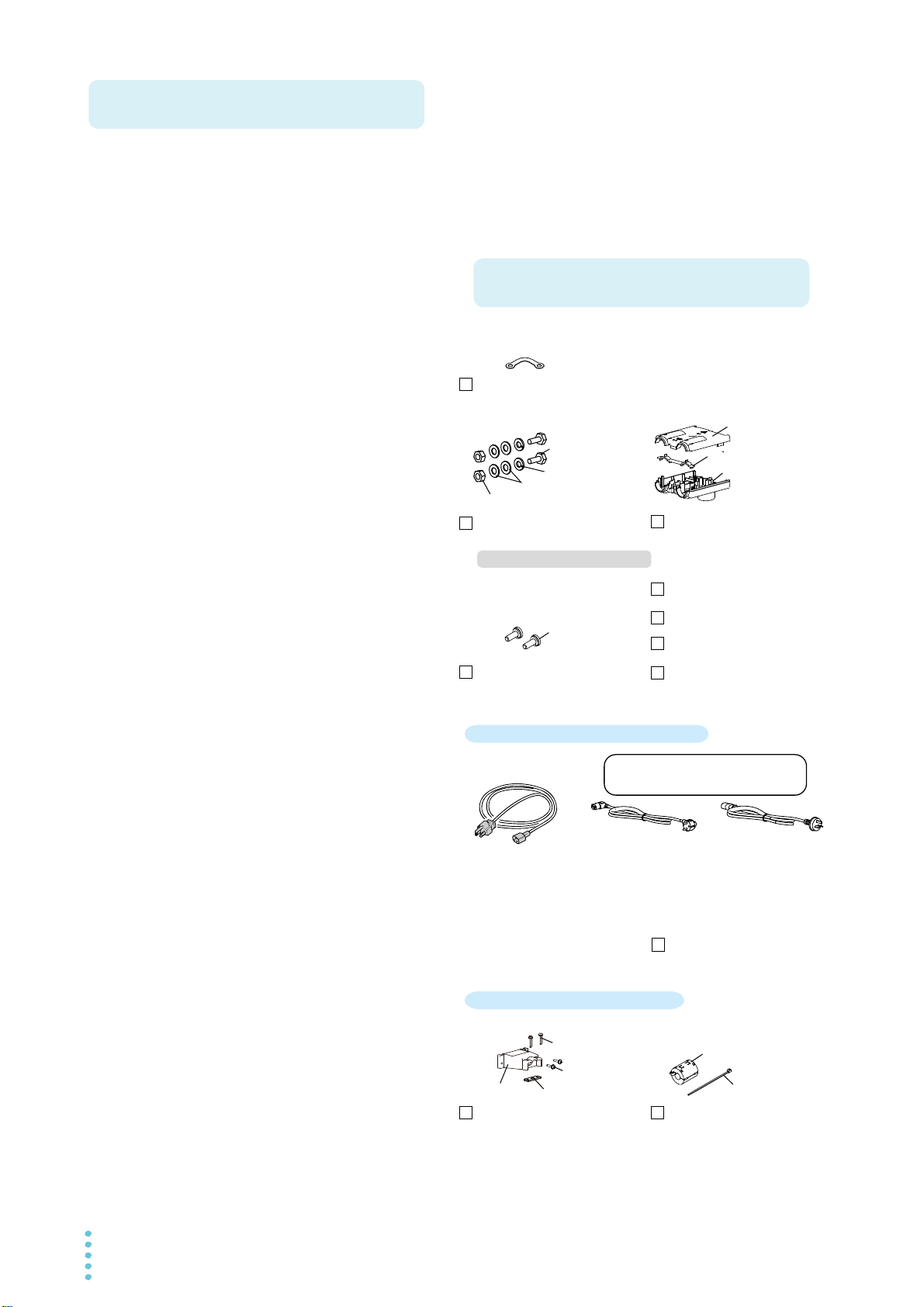
Accessories
Packing list (1 copy)
Safety Information (1 pc.)
CD-ROM (1 disk)
Output terminal M8 bolt set
(2 sets)
Output terminal M4 screws
(2 pcs.)
Chassis connection short bar (1 pc.)
Output terminal cover (1 set)
or
or
Included only with the 400W/800W model
Included only with the 1200W model
[E3-300-064]
* Only L type and ML type included.
Quick Reference
(Japanese: 1 pc, English: 1 pc.)
Power cord (1 pc.)
Rating: 125 Vac
Plug: NEMA5-15
Rating: 250 Vac
Plug: CEE7/7
Length: Approx. 2.5 m
[85-10-1070]
Rating: 250 Vac
Plug: GB1002
Length: Approx. 2.5 m
[85-10-0791]
The attached power cord varies
depending on the shipment destination.
Bottom [Q1-500-200]
Top [Q1-500-198]
Adapter [Q1-500-199]
• 400W model:
Length: Approx. 2.5 m
[85-AA-0004]
• 800W model:
Length: Approx. 3.0 m
[85-10-1030]
[M3-112-027]
[M1-100-012]
[M4-100-007]
[M5-100-007]
[M5-101-007]
Input terminal cover (1 set) Ferrite core set (1 set)
[M3-112-018]
[M3-112-015]
[P4-000-551]
[96-01-0370]
[D6-750-001]
[P1-000-410]
Power Supply and their instructors. Explanations are given
under the presumption that the reader has knowledge of the
electrical aspects of regulated DC power supplies.
PWR-01 manual construction
User’s manual (this manual, PDF)
This manual is intended for first-time users of this product. It
provides an overview of the product, notes on usage, and
specifications. It also explains how to configure the product,
operate the product, perform maintenance on the product,
and so on.
Please read this manual before you operate the product.
Communication interface manual (PDF)
This manual describes remote control and multichannel
(Virtual Multi Channel Bus).
The interface manual is written for readers with sufficient
basic knowledge of how to control power supplies using a
PC.
Copyrights
The contents of this document may not be reproduced, in
whole or in part, without the prior consent of the copyright
holder.
The specifications of this product and the contents of this document are subject to change without prior notice.
© 2017 Kikusui Electronics Corporation
Quick Reference
This document briefly explains the PWR-01 panel and the
basic operation of it.
Safety Information
This document contains general safety precautions. Keep
them in mind and make sure to observe them.
PDF files are included in the accompanying CD-ROM.
You can view the PDF files using Adobe Reader.
Firmware versions that this manual covers
This manual applies to products with firmware versions 1.0X.
When contacting us about the product, please provide us with
the following information.
Model (marked in the top section of the front panel)
Firmware version (see page 28)
Serial number (displayed on the top panel).
Trademarks
Microsoft, Internet Explorer, and Windows are registered
trademarks or trademarks of Microsoft Corporation in the
United States and/or other countries.
All company names and product names used in this manual
are trademarks or registered trademarks of their respective
companies.
2 PWR-01

The PWR-01 series is a constant voltage (CV)/constant cur-
Product Overview
rent (CC) automatic crossover power supply that can output a
wide range of voltage and current within rated output power.
The products in this series are divided into the following three
models depending on the output capacity. They are divided
into four types depending on the output voltage.
400W model 800W model 1200W model
L type
(40 V)
ML type
(80 V)
MH type
(240 V)
H type
(650 V)
PWR401L PWR801L PWR1201L
PWR401ML PWR801ML PWR1201ML
PWR401MH PWR801MH PWR1201MH
PWR401H PWR801H PWR1201H
Features
Communication function
RS232C, USB, and LAN interfaces are all installed as standard.
The remote interfaces comply with IEEE Std 488.2 1992
and SCPI Specification 1999.0.
The LAN interface complies with the LXI standard. Multichannel (VMCB), which controls up to 31 PWR-01s from a
single PC, can be used to construct a multichannel power
supply system.
Master-slave parallel operation
You can increase the output current by connecting up to
three PWR-01s (two units for the 1200W model) in parallel.
You can set one unit as the master unit, and control the
remaining units as slave units.
If an error occurs in a slave unit, the master unit detects the
alarm and shuts down the output of the entire system.
Setting preset memory function
You can save up to three sets of output settings (the combination of the voltage, current, OVP, OCP, and UVL). You
can simply select a set of output settings that you want to
use rather than having to specify each setting every time.
Automatic output-on setting
You can set the PWR-01 so that when a low AC input protection function (AC-FAIL) is activated and the output is
turned off, the output is automatically turned back on when
the problem that caused the output to turn off is fixed.
Output-on/off delay function
You can set the delay (DELAY TIME) from when the OUTPUT key is turned on or off to when the output actually turns
on or off. This is useful when you want to turn the output on
or off by setting a delay according to the load characteristics.
Set voltage/current limitation function
You can apply limits to the voltage and current settings. This
prevent you from setting an appropriate value by mistake,
which would cause the output to turn off.
Overcurrent protection (OCP) detection time setting
You can set the amount of time that an overcurrent must
persist after the first detection of the overcurrent before the
overcurrent protection (OCP) is activated. If inrush current
from the load causes an excessive current to flow temporarily, you can adjust the delay to prevent the overcurrent protection (OCP) from being activated.
Bleeder circuit function
You can turn the bleeder circuit on and off. Turn the bleeder
circuit off when you do not want the internal bleeder circuit
to sink output current. When you connect a battery, you can
prevent excessive electrical discharges by turning the
bleeder circuit off.
Soft start/ stop function
You can limit the rise time of the load current for loads that
produce inrush current when the output is turned on.
Varia bl e internal resistance function
You can easily simulate rechargeable batteries, solar batteries, fuel cells, and other power supplies that have internal
resistance. By setting the internal resistance value in constant voltage (CV) mode, you can decrease the output voltage according to the output current.
Sequence function
The sequence function recalls conditions set in a program
and runs automatically. If you write a program created on a
PC into the PWR-01, you can execute the program from the
panel.
When a program is written in the PWR-01, you can execute
the program without a PC.
CONFIG setting shortcut function and display
You can register CONFIG setting parameters to the front
panel’s SC keys. Because you do not have to go into the
CONFIG menu to set the parameters, you can perform tests
efficiently by registering CONFIG parameters that you use
frequently. Up to three parameters can be registered.
PWR-01 3
When using this product, be sure to observe the “Safety
Safety Precautions
Precautions Concerning
Installation Location
Notations Used in This Manual
WARNING
CAUTION
DESCRIPTION
Memo
Precautions” in the Safety Information manual.
When installing this product, be sure to observe the
“Precautions Concerning Installation Location” in the Safety
information manual. The following precautions pertain only to
this product.
• In this guide, the suite of products shown on the front cover
is also referred to as the “PWR-01.”
• The term “PC” is used to refer generally to both personal
computers and workstations.
• The illustrations of displays used in this manual may differ
from the actual displays. The illustrations are merely examples.
• The following markings are used in the explanations of this
text.
• When installing this product, be sure to observe the temperature and humidity ranges indicated below.
Operating temperature range: 0 °C to +50 °C (32 °F to
122 °F)
Operating humidity range: 20 %rh to 85 %rh (no condensation)
• When storing this product, be sure to observe the temperature and humidity ranges indicated below.
Storage temperature range: -10 °C to +60 °C (14 °F to
140 °F)
Storage humidity range: 90 %rh or less (no condensation)
Indicates a potentially hazardous situation which, if
ignored, could result in death or serious injury.
Indicates a potentially hazardous situation which, if
ignored, may result in damage to the product or other
property.
Indicates information that you should know.
Explanation of terminology or operation principle.
See
Indicates a reference to detailed information.
Indicates a reference to a manual containing detailed
information.
CFxx: x
“CF” indicates that this is a CONFIG parameter. The two
digits after CF indicate the CONFIG parameter number.
The value after the colon indicates the selected setting.
SHIFT+key name (blue letters)
Indicates an operation that requires you to press a key
indicated in blue characters (below the key) while holding
down SHIFT.
Indicates useful information.
4 PWR-01

Contents
About the PWR-01 Manuals ..................2
Accessories ...........................................2
Product Overview ..................................3
Features ................................................3
Safety Precautions .................................4
Precautions Concerning Installation
Location .................................................4
Notations Used in This Manual ..............4
Component Names.................................8
Installation and Prepara-
1
tion
Connecting the Power Cord ....................... 14
Load Considerations .................................. 18
Selecting the Load Cables ......................... 20
Output Terminal Insulation......................... 22
Connecting to the Output Terminals .......... 24
Turning the Power On................................ 28
Remote Sensing function........................... 30
Basic Features
2
Measured Value Display and Setting Display ..
34
Panel Operations ....................................... 36
Output Operation........................................ 37
Operation Overview ................................... 41
CV Power Supply and CC Power Supply... 43
Using the PWR-01 as a CV or CC Power
Supply ........................................................ 45
Protection functions and Alarms ................ 46
400W model/ 800W model.................. 14
1200W model ...................................... 15
When the output terminal is not grounded
(floating) ..............................................
When the output terminal is grounded 23
Connecting to the rear-panel output
terminals..............................................
Connecting to the front-panel output
terminals..............................................
Turning on the POWER switch............ 28
Turning the POWER switch off............ 29
Output on/off setting at power-on........ 37
Output-on startup state parameter ...... 37
Output-on/ off delay setting ................. 38
Soft start/ stop function........................ 39
Alarm occurrence and clearing alarms 46
Setting the protection functions........... 47
22
24
27
3
4
5
Setting limits ........................................ 52
CONFIG Settings ....................................... 54
CONFIG parameter details.................. 58
Preset Memory function ............................. 70
Saving settings .................................... 70
Recalling settings ................................ 70
Locking Panel Controls (Key Lock) ............ 71
CONFIG Shortcut function ......................... 72
Registering CONFIG shortcuts............ 72
Using CONFIG shortcuts..................... 72
Switching from Remote Mode to Local Mode..
73
Advanced Features
Bleeder Circuit function .............................. 76
Variable Internal Resistance function......... 78
Sequence function ..................................... 79
Writing and executing a sequence
program ...............................................
Synchronized Operation............................. 80
79
External Control
Product Operation ...................................... 84
About the J1/ J2 Connectors ...................... 85
Notes for Connecting External Voltage (Vext).
88
Output voltage control ................................ 90
Control using an external voltage (Vext) ..
90
Control using an external resistance (Rext)
91
Output Current Control............................... 92
Control using an external voltage (Vext) ..
92
Control using an external resistance (Rext)
93
Controlling the Output On and Off States .. 94
Controlling Output Shutdown ..................... 96
Controlling the Clearing of Alarms.............. 97
External Monitoring .................................... 98
Parallel/ Series Operation
Master-Slave Parallel Operation .............. 102
Features ............................................ 102
Connection ........................................ 104
Setting ............................................... 106
Starting master-slave parallel operation ...
107
Series operation ....................................... 108
Features ............................................ 108
Connection ........................................ 110
PWR-01 5

6
7
Setting................................................ 111
Starting series operation .................... 111
Maintenance
Calibration................................................. 114
Calibration overview........................... 114
Calibration procedure......................... 115
Cleaning.................................................... 116
Specifications
400W model.............................................. 119
800W model............................................. 122
1200W model........................................... 125
Common specifications............................ 128
Appe
ndix
A Factory Default Settings.......136
B Options......................................138
C Troubleshooting......................140
6 PWR-01

This page is intentionally blank.
PWR-01 7
Component Names
CV
CC
/
W
V
A
ALM RMT LOCK LAN
BCA
PRESET
DLY SEQ HBSSVIR
CV
CC
/
W
V
A
ALM RMT LOCK LAN
POWER
MAX10A
DC OUTPUT
POWER
SC2 SC3 LOCKALM CLR SC1
SHIFT
FINE
FINE
REGULATED DC POWER SUPPLY
OUTPUT
VOLTAGE
CURRENT
CONFIG
PWR DSPLMEMORY
LOCALSET OVP•OCP
CV
CC
/
W
V
A
AL M RMT LOCK LAN
BCA
PRESET
DLY SEQ HBSSVIR
CV
CC
/
W
V
A
AL M RMT LOCK LAN
SC2 SC3 LOCKALM CLR SC1
SHIFT
FINE
FINE
REGULA TED DC POWER SUPPLY
OUTPUT
VOLTAGE
CURRENT
CONFIG
PWR DSPLMEMORY
LOCALSET OVP•OCP
CV
CC
/
W
V
A
ALM RMT LOCK LAN
BCA
PRESET
DLY SEQ HBSSVIR
CV
CC
/
W
V
A
ALM RMT LOCK LAN
SC2 SC3 LOCKALM CLR SC1
SHIFT
FINE
FINE
REGULATED DC POWER SUPPLY
OUTPUT
VOLTAGE
CURRENT
CONFIG
PWR DSPLMEMORY
LOCALSET OVP•OCP
CV
CC
/
W
V
A
ALM RMT LOCK LAN
BCA
PRESET
DLY SEQ HBSSVIR
CV
CC
/
W
V
A
ALM RMT LOCK LAN
SC2 SC3 LOCKALM CLR SC1
SHIFT
FINE
FINE
REGULATED DC POWER SUPPLY
OUTPUT
VOLTAGE
CURRENT
CONFIG
PWR DSPLMEMORY
LOCALSET OVP•OCP
MAX10A
DC OUTPUT
POWER
MAX10A
DC OUTPUT
POWER
18
16
17
1
1
1
14
15
19
20
20
20
19
21
21
21
22
22
19
Controls
Controls
Controls
Controls
400W model
800W model
1200W model
PWR
PWR
PWR
7
8
9
6
5
2
3
4
10
11
12
13
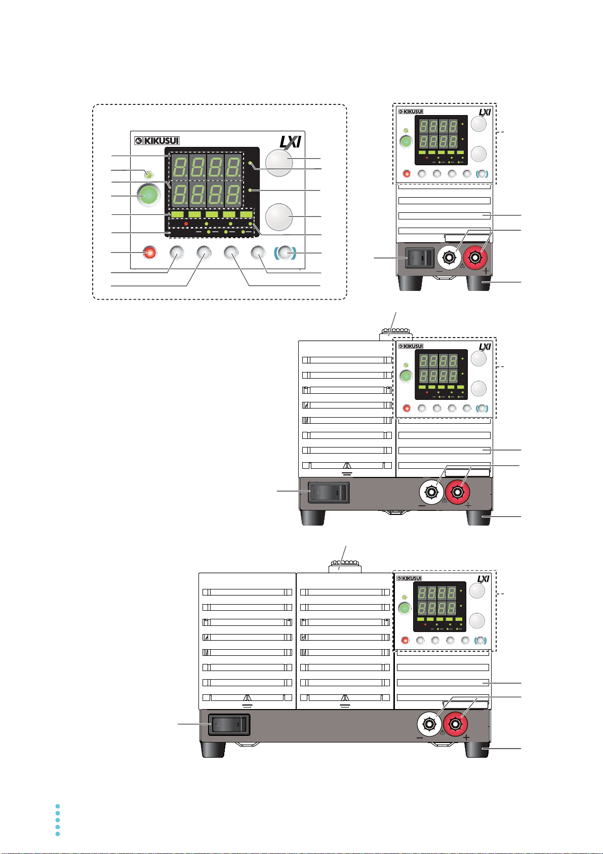
Front panel
8 PWR-01

No
See
Name Function
.
1POWER switch
Press the ( ) side to turn on and the ( ) side to turn off.
p.28, p.29
2 Voltmeter Displays the voltage, alarm, or CONFIG parameter number. p.34, p.54
3OUTPUT LED
Lights green when output is turned on. Blinks orange during output-on delay. Blinks
green during output-off delay.
Blinks orange when output is on and a protection function is activated. p.46
p.37
Lights green during soft start. Blinks green during soft stop. p.39
4 Ammeter
Displays the current, power, or the cause of an alarm, or the value of a CONFIG parameter.
p.34, p.46,
p.54
5 OUTPUT key Used to turn output on and off. p.37
6 VIR/ SS/ DLY/ SEQ/ HB
VIR: Lights when the variable internal resistance function is enabled.
SS: Lights when the soft start/ stop function is enabled and blinks when it is in progress.
DLY: Lights when the output-on/ off delay is enabled and blinks when it is in progress.
SEQ: Lights when a sequence is being executed and blinks the PWR-01 is waiting for a
trigger.
HB: Lights when the hyper bleeder of the bleeder circuit is enabled.
p.78
p.39
p.38
p.79
p.76
A: Lights green when the memory A values are being recalled or saved.
7 PRESET A/ B/ C LED
B: Lights green when the memory B values are being recalled or saved.
p.70
C: Lights green when the memory C values are being recalled or saved.
SET key Used to set and confirm the output voltage and output current (the key has an LED). p.34
8
ALM CLR key Used to release the activated state (alarm) of protection functions (the key has an LED). p.46
OVP•OCP key
9
Used to set and display the overcurrent protection (OCP), overvoltage protection (OVP),
undervoltage limit (UVL) trip points (the key has an LED).
p.47, p.52
SC1 Used to call the CONFIG parameter shortcut (the key has an LED) p.72
CONFIG key Used to configure the various operating conditions (CONFIG) (the key has an LED). p.54
10
SC2 Used to call the CONFIG parameter shortcut (the key has an LED) p.72
VOLTAGE knob Used to set the voltage value or select the value of a CONFIG parameter. p.36, p.54
11
FINE Used to make fine voltage value adjustments. p.36
12 CV LED Lights green during constant voltage mode. p.45
13 CC LED Lights red during constant current mode. p.45
CURRENT knob
14
Used to set the current, change the value of a CONFIG parameter, or set the internal
resistance value.
p.36, p.54,
p.59
FINE Used to make fine current or internal resistance value adjustments. p.36, p.59
Lights red when a protection function is activated. However, when the undervoltage limit
ALM LED
(UVL) is activated, the LED does not light. When the power limit (POWER LIMIT) is acti-
p.71
vated, the LED blinks.
RMT LED Lights green when the PWR-01 is being remotely controlled p.73
LOCK LED Lights green when the keys are locked. p.71
15
Lights and blinks when the LAN interface is running.
• No fault status (green)
LAN LED
LOCAL key
16
• Fault status (red)
• Standby status (orange)
• Identify status (blinking green)
Used to switch between local mode and remote mode (the key has an LED) and switch
the CONFIG parameter display.
Communication Interface
Manual
p.73
SHIFT key Used to enable the functions that are written in blue characters below the key. –
PWR DSPL key Used to display the output power on the ammeter (the key has an LED). p.34
17
LOCK key
Used to lock the operation of all keys other than the OUTPUT key (key lock) (the key has
an LED).
p.71
MEMORY key Used to load and save the value of preset memory A, B, or C (the key has an LED). p.70
18
SC3 Used to call the CONFIG parameter shortcut (the key has an LED). p.72
19 Air inlet (louver) Air inlet for cooling. p.116
20 DC OUTPUT connector Front-panel output terminal. p.27
21 Rubber feet Four locations on the bottom side. p.139
22 Handle Handle for carrying. p.139
PWR-01 9
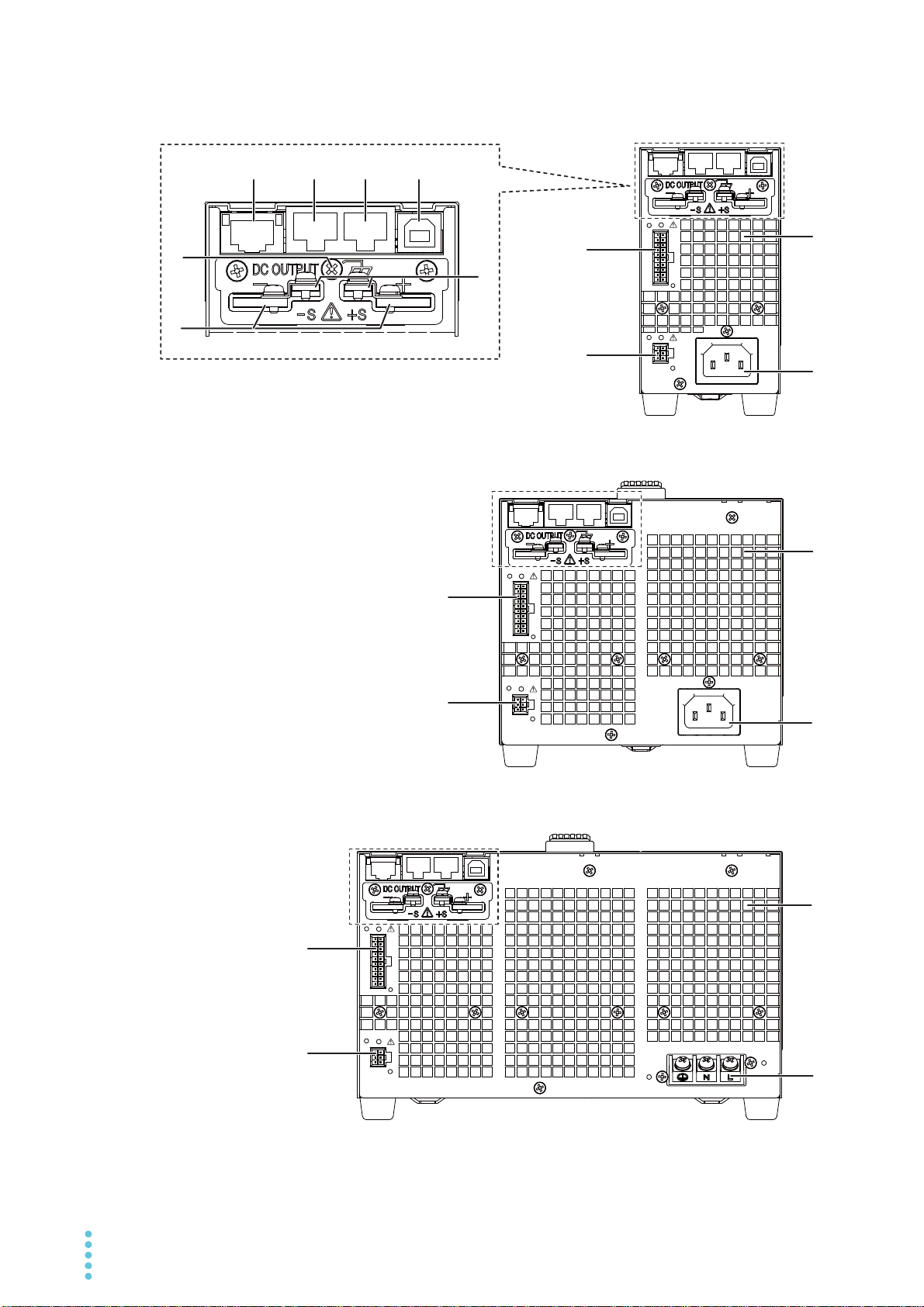
Rear Panel
J1
J2
J2
J1
J2
J1
9
8
10
11
8
8
9
9
400W model
800W model
7
456
1
3
2
10
11
10
11
1200W model
10 PWR-01

No.
See
Name Function
1 DC OUTPUT terminal Rear-panel output terminal. p.24
Chassis terminal A connector for grounding the output. p.24
2
3 LAN port
RS232C/ TRG IN
4
connector
1
1
5 TRG OUT connector
6 USB port
Sensing terminal Terminals to connect the sensing cables to. p.30
7
Air outlet Air outlet for internal cooling. –
8
1
9AC INPUT
10 J1 connector
11 J2 connector
1. A connector cover or terminal cover is attached when the product is shipped from the factory.
1
1
Ethernet port for controlling the PWR-01 remotely.
RS232C port for controlling the PWR-01 remotely.
Trigger signal input connector. The common terminal is connected to the
chassis.
Trigger signal output terminal. The common terminal is connected to the
1
chassis.
USB port for controlling the PWR-01 remotely.
400W model/ 800W model: AC inlet.
1200W model: AC INPUT terminal block.
For external control and master-slave parallel operation. p.85, p.104
External control p.85
Communication
Interface Manual
p.14
p.15
PWR-01 11

12 PWR-01
This page is intentionally blank.

Installation and Preparation
This chapter describes how to turn on the
PWR-01, what kind of load cables to use,
and how to connect cables to the output
terminals.

Connecting the Power Cord
WARNING
This product conforms to IEC Overvoltage Category II (energy-consuming equipment that is
supplied from a fixed installation).
Risk of electric shock.
• This product conforms to IEC Safety Class I (equipment that has a protective conductor terminal). Be sure to earth ground the product to prevent electric shock.
• The product is grounded through the power cord ground wire. Connect the protective conductor terminal to earth ground.
400W model/ 800W model
• Use the included power cord to connect to the AC line.
If the supplied power cord cannot be used because the rated voltage or the plug shape is
incompatible, have a qualified engineer select an appropriate power cord that is 3 m or less
in length.
• The power cord with a plug can be used to disconnect the product from the AC power line
in an emergency. Connect the plug to an easily accessible power outlet so that the plug can
be removed from the outlet at any time. Be sure to provide adequate clearance around the
power outlet.
• Do not use the dedicated power cord with other instruments.
Check that the AC power line meets the nomin al input rating of the prod-
1
uct.
The product can receive a nominal line voltage in the range of 100 Vac to 240 Vac at
50 Hz or 60 Hz.
Check that the POWER switch is turned off.
2
Connect the power cord to the AC inlet on the rear panel.
3
Insert the power plug into a grounded outlet.
4
14 PWR-01
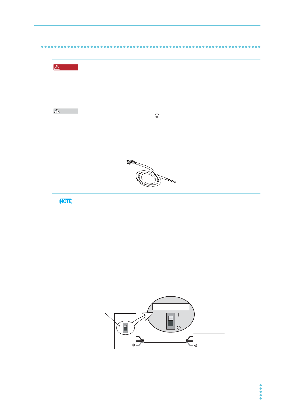
1200W model
WARNING
CAUTION
AC5.5-3P3M-M4C-VCTF
For the 1200W
model
[85-10-1010]
PWR1201L
Switchboard
Circuit breaker indication example
PWR1201L dedicated
PWR1201L
dedicated circuit breaker
N
L
N
L
Risk of electric shock.
• Before you connect the power cable, turn off the switchboard breaker (a switch that
cuts off the power supply from the switchboard).
Risk of fire.
• Be sure to have a qualified engineer make the connection to the switchboard.
• The switchboard breaker must meet the requirements shown below.
Inside the product, protection circuits are connected to match the polarity of the input termi-
nal. Be sure to connect the L, N, and (GND) terminals correctly between the switchboard
and the product.
A power cord is not included with the 1200W model. Use a power cord that conforms to the
rated AC input voltage and current of this product.
The following dedicated power cord is available as an option.
Installation and Preparation | Connecting the Power Cord
• We recommend that you use the optional dedicated power cord to connect to the AC power
line. If you will not use the dedicated power cord, use an appropriate power cord with a
length of 3 m or less that has been selected by a qualified technician.
• In an emergency, turn off the switchboard breaker to separate the product from the AC
power line.
Switchboard breaker requirements
• Rated current: 30 A (100 V system), 15 A (200 V system)
(for safety reasons, circuit breakers exceeding the specified current cannot be used)
• Only use the breaker with this product.
• Keep the breaker readily accessible at all times.
• Indicate that the circuit breaker is dedicated for use with this product and that it is used
to disconnect the product from the AC power line.
PWR-01 15
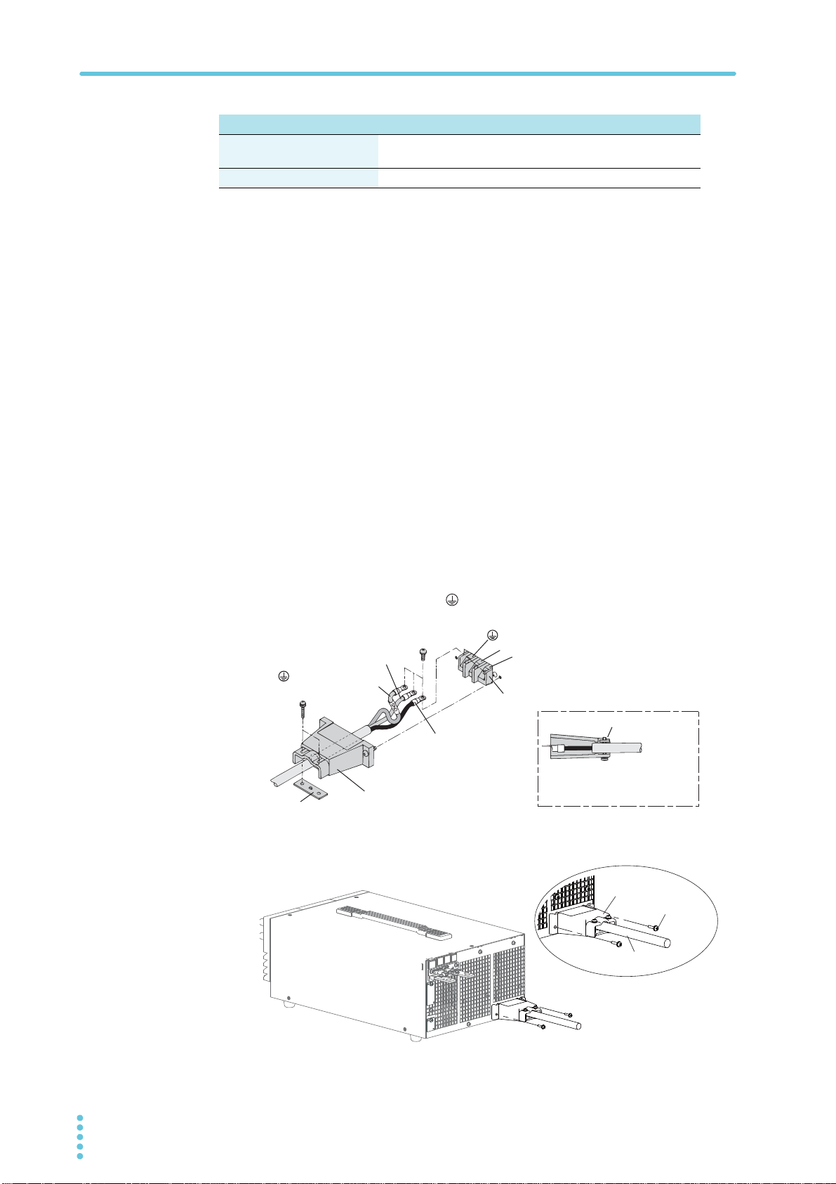
Installation and Preparation | Connecting the Power Cord
Input terminal cover
N
L
(GND)
AC INPUT terminal block
N: White or blue
L: Black or brown
Lock plate
Lock plate
(GND): Green or
green and yellow
Secure the insulated section
of the power cord in place
with a lock plate.
Power cord
Screw
Input terminal cover
400W model 800W model 1200W model
Protective conductor current
(at 265 Vac, 60 Hz)
Inrush current 25 Amax 50 Amax 75 Amax
Necessary cable
Vinyl cabtire cable (VCTF): Nominal cross-sectional area 5.5 mm
Finished diameter: 12.1 mm or less
Rated voltage: 250 V or higher
Input terminal end: Ring terminal 5.5-4 (5.5 mm
Connection procedure
Check that the AC power line meets the nomin al input rating of the prod-
1
uct.
The product can receive a nominal line voltage in the range of 100 Vac to 240 Vac at
50 Hz or 60 Hz.
1.5 mA 2.5 mA 4.0 mA
2
M4)
2
3core
Check that the POWER switch is turned off.
2
Connect the power cord to the AC INPUT terminal on the rear panel.
3
Pass the power cord through the included INPUT terminal cover, and fix
the cord in place using the lock plate and screws.
Be sure to connect the L, N, and (GND) of the AC input terminal correctly.
Attach the INPUT terminal cover using the screws on the PWR-01 .
4
16 PWR-01
Attach the included ferrite core to the power cord.
5
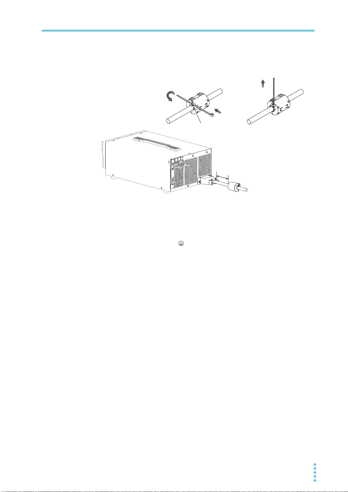
Installation and Preparation | Connecting the Power Cord
Insert the cable tie
through here.
Firmly apply the cable tie to
attach the core to the power
cord.
Approx. 10 cm
1
2
3
Attach the core as close to the input terminal as possible but not too close as to get in
the way of attaching and removing the INPUT terminal cover.
Use the cable tie to fix the core on to the power cord. Check that the core is locked
and does not move. Cut the cable tie at an appropriate length.
Attach a appropriate crimping terminal to the switchboard end of the
6
power cord.
Turn off the switchboard’s circuit breaker.
7
Connect the L, N, and (GND) wires of the power cord to the matching
8
terminals on the switchboard.
PWR-01 17
Load Considerations
Constant current setting
Ammeter reading (mean value)
Constant current setting
Ammeter reading (mean value)
O
RD
EO
Equivalent circuit of the PWR-01
Regenerative load
í
0
Reverse current
+IO
+
Irp
RDLQ
RD
EO: Output voltage
Irp: Maximum reverse current
(2LQ9
,USLQ$
Load
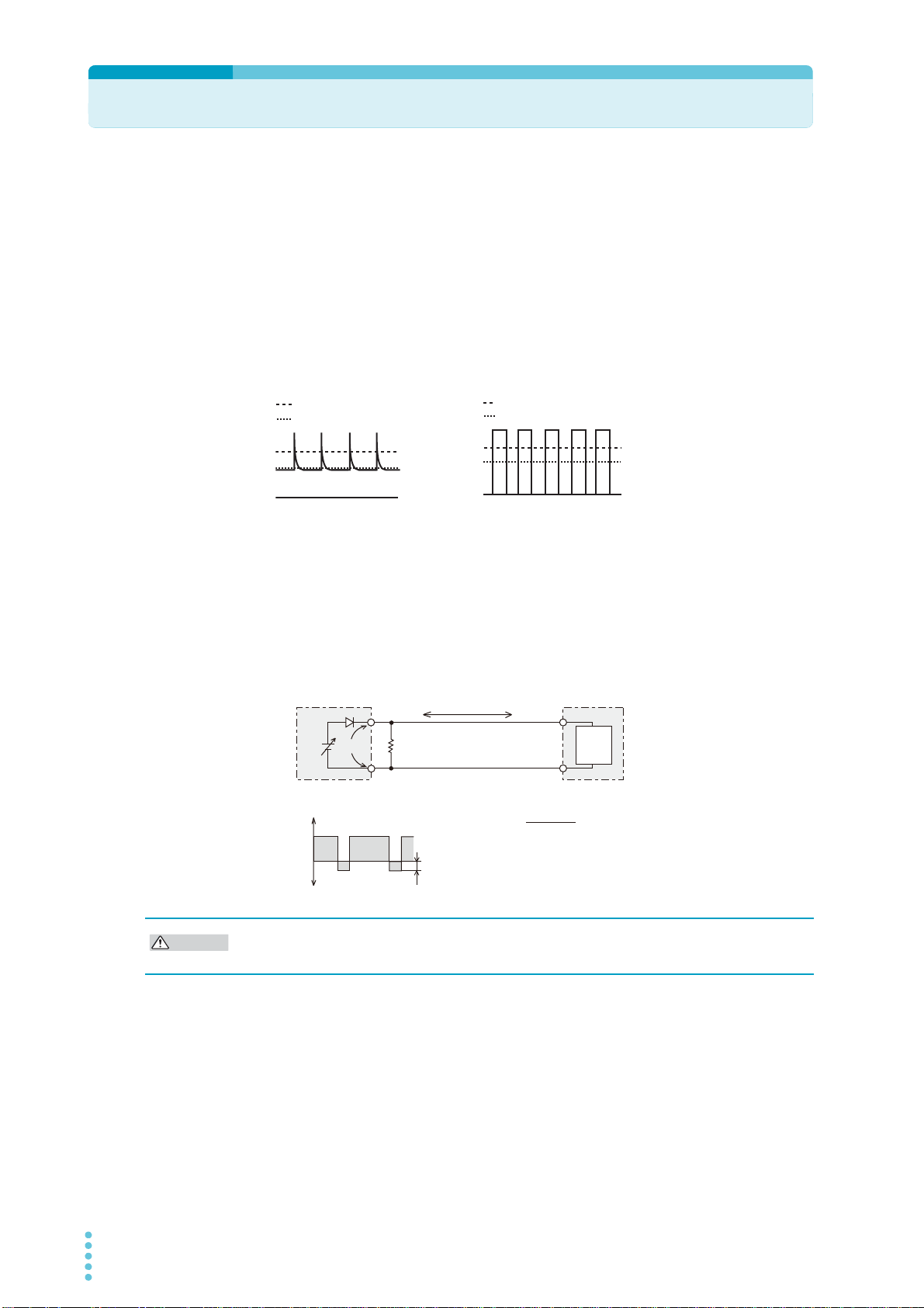
CAUTION
Note that the output will become unstable if the following types of loads are connected.
Loads with peak current or pulse-shaped current
The PWR-01 only indicates mean values. Even when the indicated value is less than or equal
to the set constant current, the peak values may exceed the set constant current. If this happens, the PWR-01 is instantaneously put into constant-current mode, and the output voltage
drops.
For these types of loads, you must increase the set constant current or increase the current
capacity.
Load current with peaks Pulse-shaped load current
Loads that generate reverse current to the power supply
The PWR-01 cannot absorb reverse current from the load. Therefore, if a regenerative load
(such as an inverter, converter, or transformer) is connected, the output voltage increases
and becomes unstable. This can cause a malfunction.
For these types of loads, connect a resistor (RD) as shown in the following figure to bypass
the reverse current. However, the amount of current to the load decreases by Irp.
I
: Reverse current bypass dummy load
Output current
-IO
Use a resistor with sufficient rated power for RD. If a resistor with insufficient rated power for
the circuit is used, resistor RD will burn out.
18 PWR-01
Installation and Preparation | Load Considerations
This product
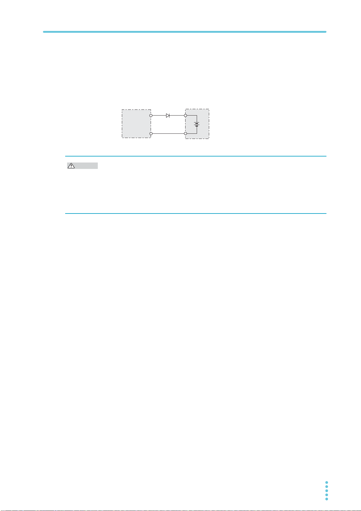
Load with accumulated energy
DRP: Reverse-current-protection diode
D
RP
CAUTION
Loads with accumulated energy
Connecting a load with accumulated energy, such as a battery, to the PWR-01 may cause
current to flow from the load to the internal circuit of the PWR-01. This current may damage
the PWR-01 or reduce the life of the load.
For this type of load, connect a reverse-current-prevention diode (DRP) between the PWR-01
and the load in series as shown in the following figure.
This cannot be used in conjunction with remote sensing.
• To protect the load and the PWR-01, use a DRP that conforms to the following
specifications.
Reverse voltage withstand capacity: At least twice the rated output voltage of the PWR-01.
Forward current capacity: 3 to 10 times the rated output current of the PWR-01.
A diode with small loss.
• Be sure to take into account the heat generated by D
heat dissipation.
RP. DRP will burn out with inadequate
PWR-01 19
Selecting the Load Cables
WARNING
CAUTION
Risk of fire.
• Use load cables whose capacity is adequate for the PWR-01’s rated output current.
• The output terminal and its surrounding area become very hot. Use cables whose
covers have an allowable temperature of 85 °C or higher.
Risk of electric shock.
• Use load cables with a voltage rating that meets or exceeds the product’s isolation
voltage. For details on the PWR-01’s isolation voltage, see Chap.7 "Specifications"(p.117).
• Use load cables with a core diameter that is appropriate for the amount of current being
used and with sturdy, flame-resistant insulation.
Current capacity of load cables
A cable’s temperature is determined by the resistive loss based on the current, the ambient
temperature, and the cable’s external thermal resistance. The following table shows the current capacity of heat-resistant vinyl cables that have a maximum allowable temperature of
60 °C when one of the cables is separated and stretched out horizontally in air in an ambient
temperature of 30 °C. The current must be reduced under certain conditions, such as when
vinyl cables that have a low heat resistance are used, when the ambient temperature is 30 °C
or greater, or when cables are bundled together and little heat is radiated.
Nominal cross-
sectional area (mm
2 14 (2.08) 27 10
3.5 12 (3.31) 37 -
5.5 10 (5.26) 49 20
8 8 (8.37) 61 30
14 6 (13.3) 88 50
22 4 (21.15) 115 80
30 2 (33.62) 139 -
38 1 (42.41) 162 100
50 1/0 (53.49) 190 -
60 2/0 (67.43) 217 -
80 3/0 (85.01) 257 200
100 4/0 (107.2) 298 -
1 Excerpt from Japanese laws related to electrical equipment.
AWG (reference cross-
2
sectional area; mm
)
2
)
Allowable current1(A)
(Ta = 30 °C)
Kikusui-recommended current (A)
Taking measures against noise
When connecting cables that have the same heat resistance, separating the cables as much
as possible to increase heat radiation enables a greater amount of current to flow. However,
wiring the + (positive) and - (negative) output wires of the load cable side by side or bundling
them together is more effective against unwanted noise. The Kikusui-recommended currents
shown in the above table are allowable currents that have been reduced in consideration of
the potential bundling of load cables. Use these values as a guideline when connecting
cables.
20 PWR-01

Installation and Preparation | Selecting the Load Cables
Limitations of the remote sensing function
All wires have resistance. As the wire becomes longer or the current becomes larger, the voltage drop in the wire becomes greater. This results in a smaller voltage being applied at the
load end. The PWR-01 has a sensing function that compensates for this voltage drop up to
the following values (p.30). If the voltage drop exceeds this level, use cables that have a
greater cross-sectional area.
L type ML type MH type H type
Compensation
voltage
Approx. 1.5 V one
way
Approx. 4 V one
way
Approx. 5 V one
way
Approx. 5 V one
way
PWR-01 21
Output Terminal Insulation
WARNING
CAUTION
+
–
+
+S
–S
–
+
–
16
17
18
19
14
15
20
2
3
4
5
6
13
12
11
10
9
8
7
1
2
3
4
5
6
1
AC
DC
OUTPUT
J1 J2
SENS
L
N
Load
Rext
PWR-01
Vext
Approximately the same
electric potential as the
negative output terminal
All pins of the J1 connector are at
approximately the same electric
potential as the PWR-01’s negative output terminal.
Risk of electric shock. For safety reasons, even if the output terminal is grounded,
make sure that the insulation capacity of the output terminal (including the sensing
terminal) is greater than or equal to the isolation voltage of this product.
For details on the isolation voltage of each model, see "Specifications" (p.117).
If you cannot obtain a cable with sufficient rated voltage, secure adequate withstand
voltage by passing the cable through an insulation tube with a withstand voltage
greater than the isolation voltage of the PWR-01.
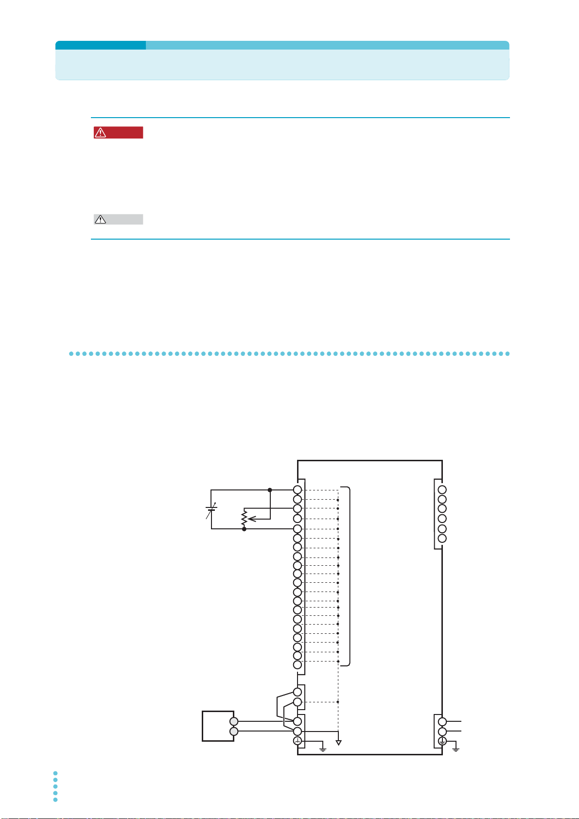
The signal cable may burn out. If the PWR-01 is to be controlled through an external voltage
(Vext), do not ground the external voltage (leave it floating).
The cable and load that are connected to the output terminal (including the sensing terminal)
must have an insulation capacity that is greater than or equal to the isolation voltage of the
PWR-01 with respect to the chassis. Isolation voltage indicates the maximum allowed voltage
that appears across the output terminal of the power supply unit and the protective conductor
terminal (chassis terminal).
When the output terminal is not grounded (floating)
The output terminal of the PWR-01 is isolated from the protective conductor terminal. If you
connect the GND wire of the power cord to the ground terminal of the switchboard, the chassis of the PWR-01 is set to ground potential.
The J1 connector on the rear panel are at approximately the same electric potential as the
PWR-01’s negative output terminal. Cables and devices that are connected to these pins
must have an insulation capacity greater than or equal to the isolation voltage of the PWR-01.
INPUT
22 PWR-01
Installation and Preparation | Output Terminal Insulation
+
–
+
+S
–S
–
+
–
16
17
18
19
14
15
20
2
3
4
5
6
13
12
11
10
9
8
7
1
2
3
4
5
6
1
AC
INPUT
DC
OUTPUT
J1 J2
SENS
L
N
Load
Rext
PWR-01
Vext
Chassis terminal
Approximately the
same electric potential
as the negative output
terminal
All pins of the J1 connector are
at approximately the same electric potential as the PWR-01’s
negative output terminal.
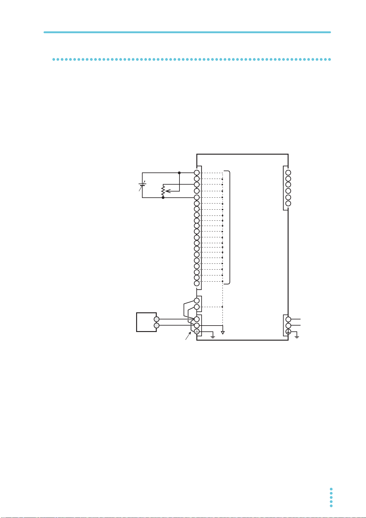
When the output terminal is grounded
If the positive output terminal is connected to the chassis terminal, the positive output terminal is at ground potential. The cable and load that are connected to the output terminal
(including the sensing terminal) will only require an insulation capacity that is greater than or
equal to the maximum output voltage of the PWR-01 with respect to the chassis.
The same holds true when the negative terminal is connected to the chassis terminal. The
cable and load require an insulation capacity that is greater than or equal to the maximum
output voltage of the PWR-01.
For safety reasons, connect one of the output terminals to the chassis terminal unless your
application requires the output terminals to be floating.
PWR-01 23
Connecting to the Output Terminals
WARNING
Chassis terminal
íQHJDWLYHWHUPLQDO
SRVLWLYHWHUPLQDO
800W model example
Chassis connection short bar
Screw (M3)
Screw (M3)
400W model
Example of connecting to the negative terminal
Risk of electric shock.
• Turn the POWER switch off before you touch the rear-panel output terminals.
• Even if you turn the out put off or turn the POWER switch off, if the bleeder circuit is
set to off (CF01: DIS), the voltage that was present when the output was on will
remain at the output terminals. Set the bleeder circuit to on (CF01: NORM/ HYP)
before you touch the output terminals.
• Regardless of whether load cables are connected to the output terminals, be sure to
attach the OUTPUT terminal cover before turning the POWER switch on.
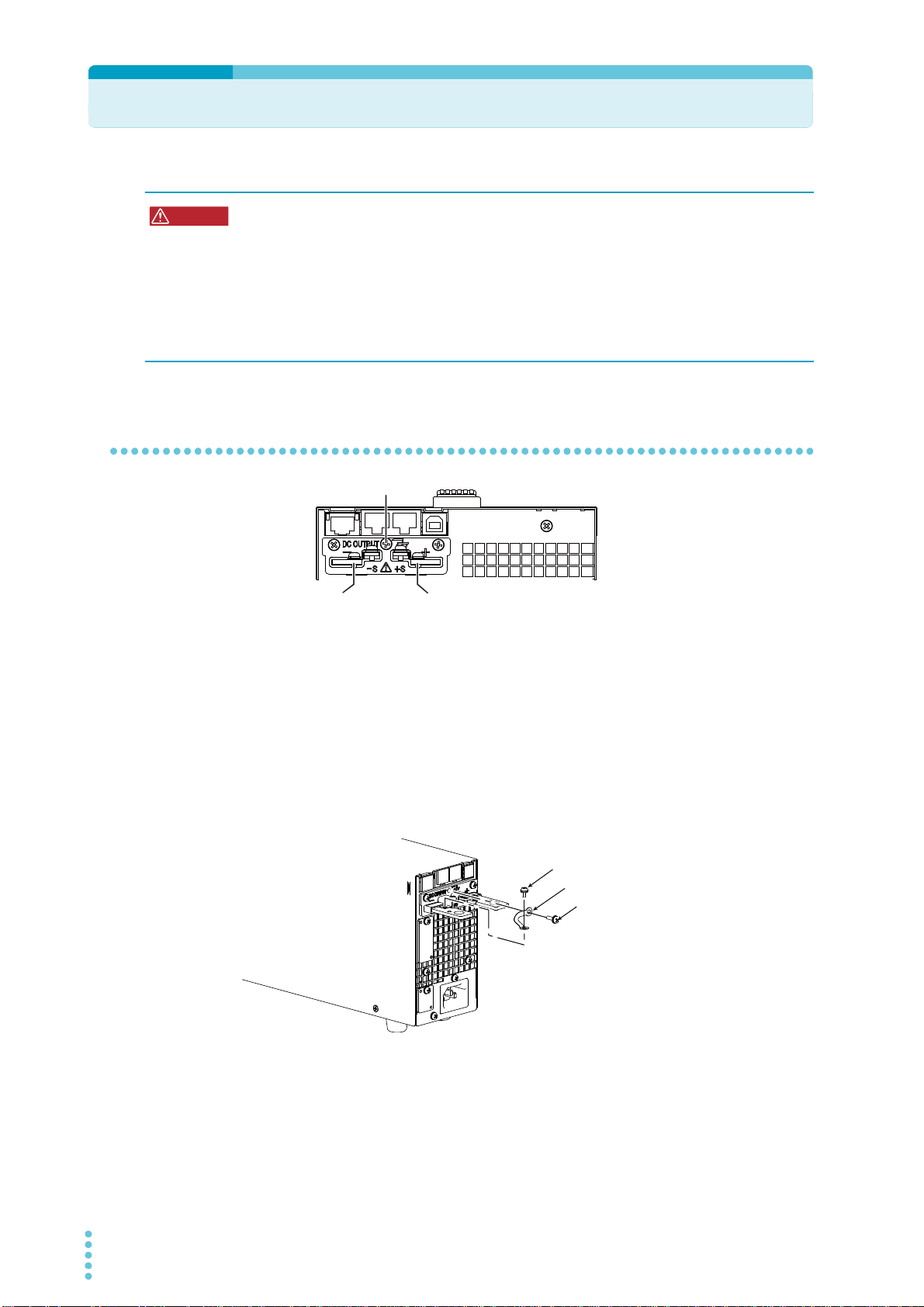
Connecting to the rear-panel output terminals
Turn the POWER switch off.
1
Check that there is no residual voltage at the rear-panel output terminals.
Connect one end of the included chassis connection short bar to the
2
chassis terminal and the other end to the negative or positive output terminal.
Use the screw on the PWR-01 to connect the short bar to the chassis terminal. Use the
screw on the rear-panel output terminal to connect the short bar to the output terminal.
If you are not grounding the output terminal (leaving it floating), refer to “Output Termi-
nal Insulation” (p.22) before use.
Attach crimping terminals to the load cables.
3
The rear-panel output terminals have holes for connecting the load cables. Use crimping terminals that are appropriate for the bolts that you are using.
24 PWR-01
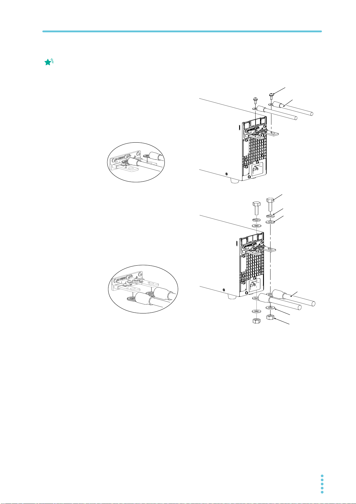
Memo
If you do not connect load
Spring washer
(M8)
Washer (M8)
Washer (M8)
Bolt (M8)
Load cable
Using the M8 bolt set to connect the cables
Cable diameter (including the insulation)
ø8 to ø17
Applicable models
L type, ML type
Screw (M4)
Load cable
Connection using the M4 screw set
Cable diameter (including the insulation)
Up to ø7
Applicable models
All models
400W model example
Bring the ring to the bottom
side, and align to the bottom
of the output terminal.
cables in the correct
orientation, you will not be
able to attach the
OUTPUT terminal cover.
Installation and Preparation | Connecting to the Output Terminals
Connect the load cables to the rear-panel output terminals.
4
Use the included screw set.
To reduce the influence of noise on the output, keep the cables as short as possible. If
possible, twist the positive and negative load cables.
Bring the ring to the bottom
side, and align to the top side
Nut (M8)
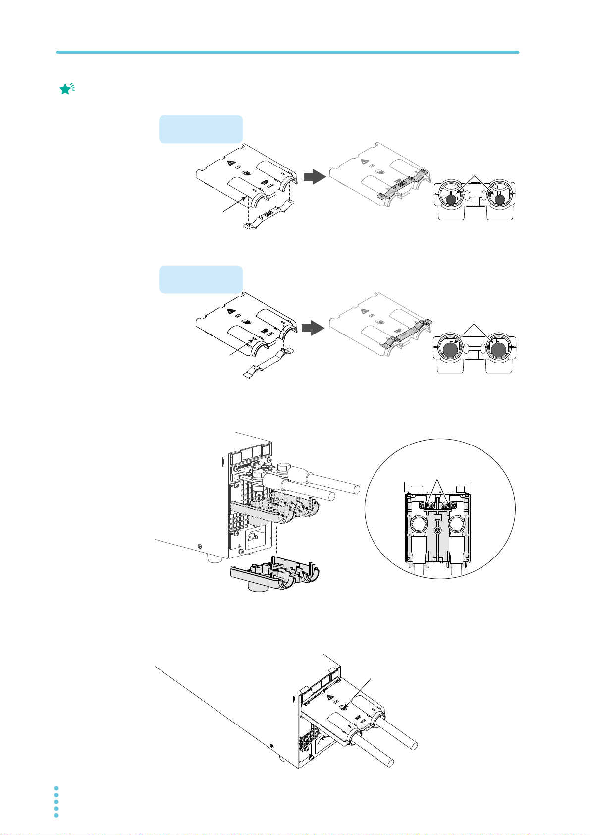
Attaching the OUTPUT terminal cover
You can adjust the diameter of the holes that the load cables pass through by changing the
orientation of the adapter attached to the OUTPUT terminal cover. There are two available
orientations. Use the appropriate orientation for the load cables (including the insulation) that
you are using.
• Cable diameter (including the insulation) up to ø7: Attach the adapter of the OUTPUT
terminal cover so that the hole diameter is small.
• Cable diameter (including the insulation) from ø8 to ø17: Attach the adapter of the
OUTPUT terminal cover so that the hole diameter is large.
PWR-01 25
Installation and Preparation | Connecting to the Output Terminals
Memo
Top half of the cover
For thin load cables
Cable diameter
(including the insulation)
ø8 to ø17
Cable diameter
(including the insulation)
Up to ø7
For thick load cables
Top half of the cover
Example of the load
cable position
Example of the load
cable position
Insert the adapter
tabs into the two
cuts in the top half
Insert the adapter
tabs into four two
cuts in the top half
Align the cover to the cut-out in
the rear-panel output terminal.
400W model example
After you have lined up the top and
bottom halves of the cover, use the
screws to fix the cover in place.
Screw (M3)
400W model example
Attach the adapter to the top half of the OUTPUT terminal cover.
1
The top and bottom
halves of the OUTPUT
terminal cover have
different shapes.
Insert the adapter tabs into the cuts in the OUTPUT terminal cover.
2
3
Align the bottom half of the OUTPUT terminal cover to the rear-panel
output terminals.
Place the top half of the OUTPUT terminal cover over the bottom half,
and screw them together.
Make sure that the screws are securely fastened.
26 PWR-01
Installation and Preparation | Connecting to the Output Terminals
WARNING
Front-panel output terminal.
- (negative) terminal
+ (positive) terminal
Safety plugs
800W model example
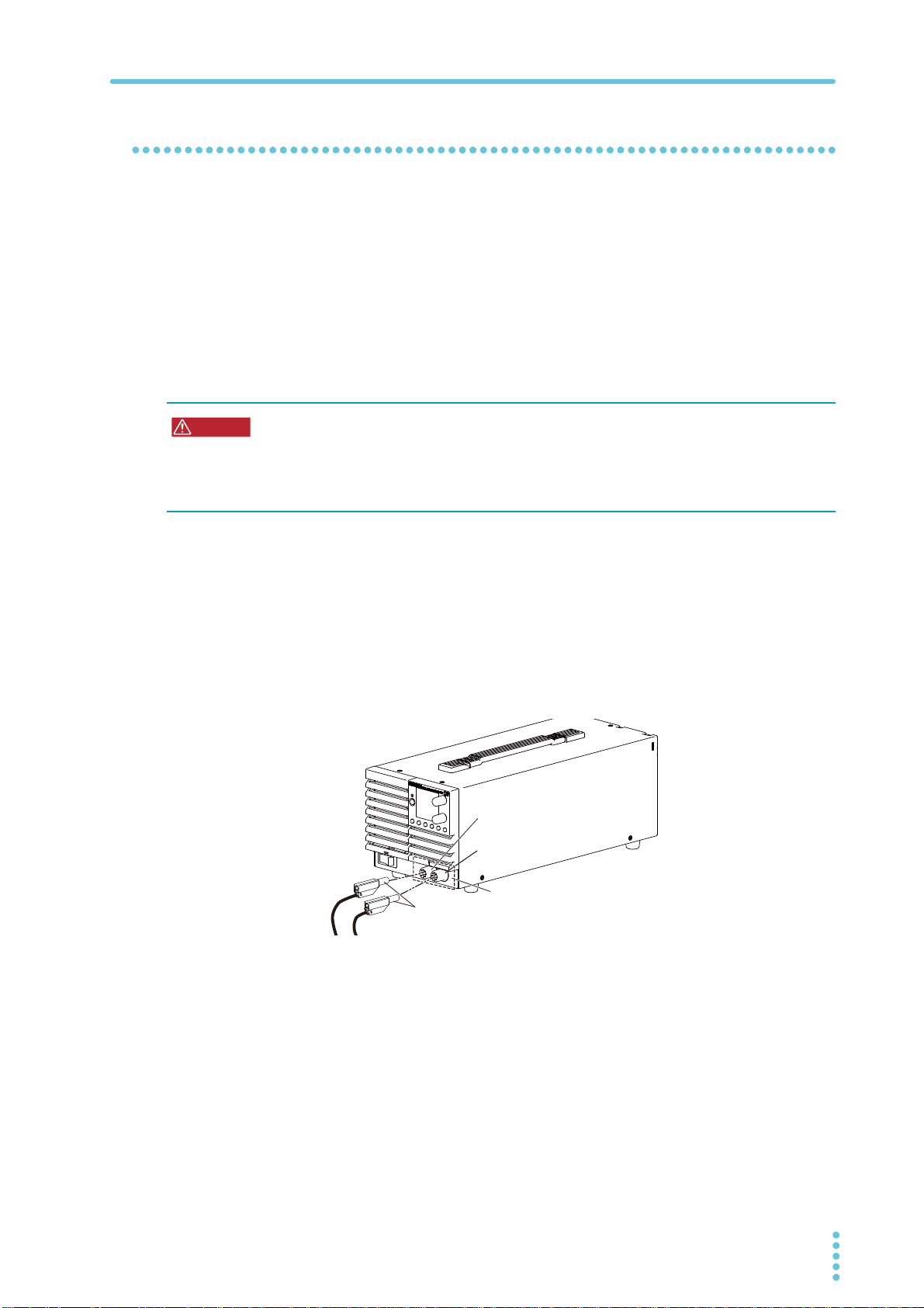
Connecting to the front-panel output terminals
The specifications of the PWR-01 apply to the rear-panel output terminals. The front-panel
output terminals may not meet the specifications.
There is no grounding terminal on the front-panel output terminals. To ground one side of the
output, connect the rear-panel chassis terminal to either the negative output terminal or the
positive output terminal.
If you are not grounding the output terminal (leaving it floating), refer to “Output Terminal
Insulation” (p.22) before use.
If the output current of the front-panel output terminals exceeds 10 A (typical value), the front-
panel output terminal overcurrent protection (FOCP) will be activated (p.50).
• Risk of electric shock. The front-panel output terminals are designed to be used with
safety plugs. Do not use connectors that have bare conductive parts (such as
banana plugs) to connect to the front-panel output terminals.
• Risk of heat buildup or fire.
Do not run current higher than 10 A through the front-panel output terminals.
Necessary cables and plugs (recommended)
Polyvinyl chloride insulation cable: Nominal cross-sectional area of 0.33 mm2 (AWG22) to
0.82 mm
Rated voltage: 1000 V or higher
Length: Less than 3 m
Output terminal plugs: Safety plugs
Safety plugs TL41 and TL42 are available as options (p.139).
1
2
(AWG18)
Attach safety plugs to the load cables.
Connect the load cables with safety plugs to the front-panel output ter-
2
minals.
To reduce the influence of noise on the output, keep the cables as short as possible.
Twist the positive and negative load cables.
PWR-01 27
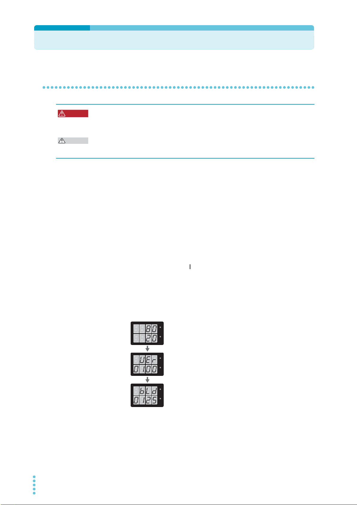
Turning the Power On
WARNING
CAUTION
Firmware version display
(Version 1.00 in this example)
Rated voltage and rated current display
(PWR401ML example)
Build number display
(Build number BLD 0125 in this example)
CV
CC
/
W
V
A
CV
CC
/
W
V
A
CV
CC
/
W
V
A
CV
CC
/
W
V
A
CV
CC
/
W
V
A
CV
CC
/
W
V
A
Turning on the POWER switch
Risk of electric shock. Regardless of whether load cables are connected to the output
terminals, be sure to attach the OUTPUT terminal cover before turning the POWER
switch on.
Risk of damage to load.
If the PWR-01 is configured to turn on the output when the POWER switch is turned on in
CONFIG settings, set an appropriate OVP or OCP value before connecting a different load.
If the POWER switch is turned on for the first time after purchase, the PWR-01 starts in the
factory default condition (p.136). Subsequent times that you turn the PWR-01 on, it starts with
the panel settings (excluding the output on/off setting) that were in use immediately before
the POWER switch was turned off.
You can use the CONFIG settings (CF45) to select the output state of the PWR-01 when the
POWER switch is turned on (p.65).
Check that the power cord is connected correctly.
1
Check that the OUTPUT terminal cover is attached (p.25).
2
When the product is shipped from the factory, the OUTPUT terminal cover is not
attached.
Turn the POWER switch on ( ).
3
All the indicators light, and then the voltmeter and the ammeter display the following
sequence of information: the rated voltage and rated current, the firmware version
number, and then the build number. Each item is displayed for approximately 1 second.
After a few seconds, the PWR-01 enters the operation standby state (the measured
value is displayed).
28 PWR-01

Installation and Preparation | Turning the Power On
CAUTION
Turning the POWER switch off
Turn the POWER switch off ( ).
The PWR-01 saves the panel settings (except the output on/off setting) that were in use
immediately before the POWER switch was turned off.
You can use the CONFIG settings (CF45) to select the output state of the PWR-01 when the
POWER switch is turned on (p.65).
If the POWER switch is turned off immediately after the settings have been changed, the last
settings may not be stored.
After you turn the POWER switch off, wait at least 10 seconds after the panel display turns
off before you turn the POWER switch back on. Repeatedly turning the POWER switch on
and off at short intervals can cause damage to the inrush current limiter. Furthermore, this
will shorten the service life of the POWER switch and the internal input fuse.
PWR-01 29

Remote Sensing function
E3-200-546
WARNING
Remote sensing is a function that stabilizes the output voltage across the load by reducing
the influence of voltage drops and other effects caused by the load cable resistance.
The PWR-01 remote sensing can compensate up to the values shown below. Select a load
cable that has sufficient current capacity to prevent the voltage drop in the load cable from
exceeding the compensation voltage.
When you perform remote sensing, set the voltage of the sensing point (across the load) so
that it does not exceed the rated output voltage. If you are performing remote sensing with
the voltage close to the maximum output voltage, the output is limited by the maximum output
voltage (105 % of the rated output voltage). Electrolytic capacitors may be required at the
sensing point (across the load).
To reduce the effect of noise, use twisted-pair cables or 2-core shielded cables. When you
use shielded cables, connect the shield to the PWR-01 or the load grounding terminal.
L type ML type MH type H type
Compensation
voltage
When the product is shipped from the factory, a sensing short bar
is connected across the sensing terminals and DC OUTPUT terminals. When the sensing terminals are not used, connect the sensing short bar.
If the short bar is damaged or lost, contact your Kikusui agent or
distributor.
Approx. 1.5 V one
way
Approx. 4 V one
way
Approx. 5 V one
way
Approx. 5 V one
way
Connecting the sensing cables
Risk of electric shock and damage to internal circuits.
• Never wire the sensing terminals while the POWER switch is turned on.
• For sensing cables, use cables with a voltage rating that is higher than the PWR-01’s
isolation voltage. Protect the uncovered sections of the shielded cable by using
insulation tubes whose withstand voltage is greater than the PWR-01’ isolation voltage.
• Even if you turn the out put off or turn the POWER switch off, if the bleeder circuit is
set to off (CF01: DIS), the voltage that was present when the output was on will
remain at the output terminals. Set the bleeder circuit to on (CF01: NORM/ HYP)
before you touch the sensing terminals.
• Be sure to attach the OUTPUT terminal cover before turning the POWER switch on.
30 PWR-01
 Loading...