

Kikusui PWR400L, PWR800L, PWR1600L, PWR400M, PWR800M Setup Manual
...
PART NO. Z1-005-550, IA004953
Jan. 2017
Features
Setup Guide
Regulated DC Power Supply PWR Series
400W Type 800W Type 1600W Type
PWR400L PWR800L PWR1600L
PWR400M PWR800M PWR1600M
PWR400H PWR800H PWR1600H
Thank you for purchasing the PWR regulated DC power supply series.
The PWR Series are constant voltage/current automatic crossover
power supplies that are capable of delivering voltages and currents
in a wide operating range within the rated output power.
KIKUSUI ELECTRONICS CORP.
1-1-3, Higashiyamata, Tsuzuki-ku, Yokohama, 224-0023, Japan
TEL: +81-45-593-0200 Fax: +81-45-593-7571
The contents of this manual may not be reproduced, in whole or in part, without the
prior consent of the copyright holder.
The specifications of this product and the contents of this manual are subject to
change without prior notice.
• Power-factor improvement circuit
The power-factor improvement circuit reduces the effects of har-
monic currents on the power line.
• High efficiency
The high power conversion efficiency reduces the cost of power
and the cost of heat radiation design during system configuration.
• Communication functions
Equipped with a digital remote control function through TP-BUS
(Twist Pair-BUS) communication (The total length of TP-BUS is
200 m). By combining with Kikusui’s PIA4800 Series Power Supply Controller, systemization for applications such as an automatic tester is possible.
• Master-slave operation
Output voltage or output current can be expanded by connect-
ing multiple power supplies of the same model in series (only
on the L type) or in parallel. This feature allows slave units to be
controlled from a single master unit.
WEBSITE
The newest version of the PWR manual can be downloaded
from Download service of Kikusui website.
© 2012
http://www.kikusui.co.jp/en
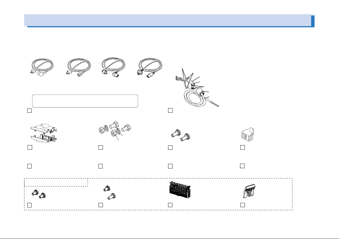
Checking the Package Contents
Accessories
.
When you receive the product, check that all accessories are included and that the accessories have not been damaged during transportation. If any of the accessories are damaged or missing, contact your Kikusui agent or distributor. The power cord varies depending on the type.
or
Plug:NEMA5-15
Rating:125Vac/10A
[85-AA-0003]
The power cord that is provided varies depending on
the destination for the product at the factory-shipment.
Power cord for the 400W/800W type
OUTPUT terminal cover
CD-ROM (1 pc.)
Plug:NEMA5-15
Rating:125Vac/10A
[85-10-0740]
1 set
[Q1-500-077]
or
Pulg: CEE7/7
Rating: 250Vac/10A
[85-10-1070]
2 sets
M8 output terminal screws
Safety information (1 pc.)
or
Pulg: GB1002
Rating: 250Vac/10A
[85-10-0790]
[M1-100-011]
[M5-101-007]
[M4-100-007]
Accompanying nuts: [M8-500-003] 2 pcs.
Accompanying screws A: [M3-112-015] 2 pcs.
Cable clamp: [P1-000-055] 1 pc.
Fastening plate: [D6-750-001] 1 pc.
Accompanying screws B: [M3-112-017] 2 pcs.
EMI core: [96-01-0180] 1 pc.
Cable: [85-10-1010] 1 pc.
Power cord for the 1600W type (with cable clamp and no plug)
2 pcs.
[M3-112-026]
M4 output terminal screws
Setup Guide (This guide, 1 pc.) Quick Reference
1 pc.
[84-61-5102]
TP-BUS connector
English 1 pc. , Japanese 1 pc
These parts are installed in body.
2 pcs.
[M3-112-012]
M3 sensing terminal screws
1 pc. [M3-112-012]
1 pc. [M3-112-015]
M3 screws for chassis connection wire
1 pc.
[84-49-0110]
J1protection socket
1 pc.
[83-06-5060]
J1 lock lever
2 PWR Series Setup Guide
About the PWR Manual
The PWR manual is intended for users of the PWR regulated DC power
supply series or persons teaching other users on how to operate them.
The manual assumes that the reader has knowledge about electrical
aspects of regulated DC power supplies.
The PWR manual comprises the Setup Guide (this guide), the User’s
Manual (Basic operation, External control, Parallel/Series operation,
Maintenance, and Specifications), the Connecting & Programming
Guide, the Quick Reference, and the Safety information.
The user's manual and the connecting & programming guide are provided on the accompanying CD-ROM.
Adobe Reader is required to view the PDF files. Microsoft Internet
Explorer or Google Chrome is required to view the HTML files.
Put the included CD-ROM into the CD-ROM drive. In a few moments, a
start window will appear. If the start window does not appear, open the
CD-ROM folder in Windows Explorer, and then double-click index.html
to display the start window.
Every effort has been made to ensure the accuracy of the manual. However, if you have any questions or find any errors or omissions, please
contact your Kikusui agent or distributor.
If you find any misplaced or missing pages in the manual, it will be replaced. If the manual gets lost or soiled, a new copy can be provided
for a fee. To replace or purchase a manual, please contact your Kikusui
agent or distributor. At that time, inform your agent or distributor of the
“Part No.” written on the front cover of this manual.
In the manual, the PWR Series Regulated DC Power Supply is also referred to as the PWR Series and the PWR.
The display illustration used in the manual may differ from the actual
displays that appear on the PWR. The screen captures are merely examples.
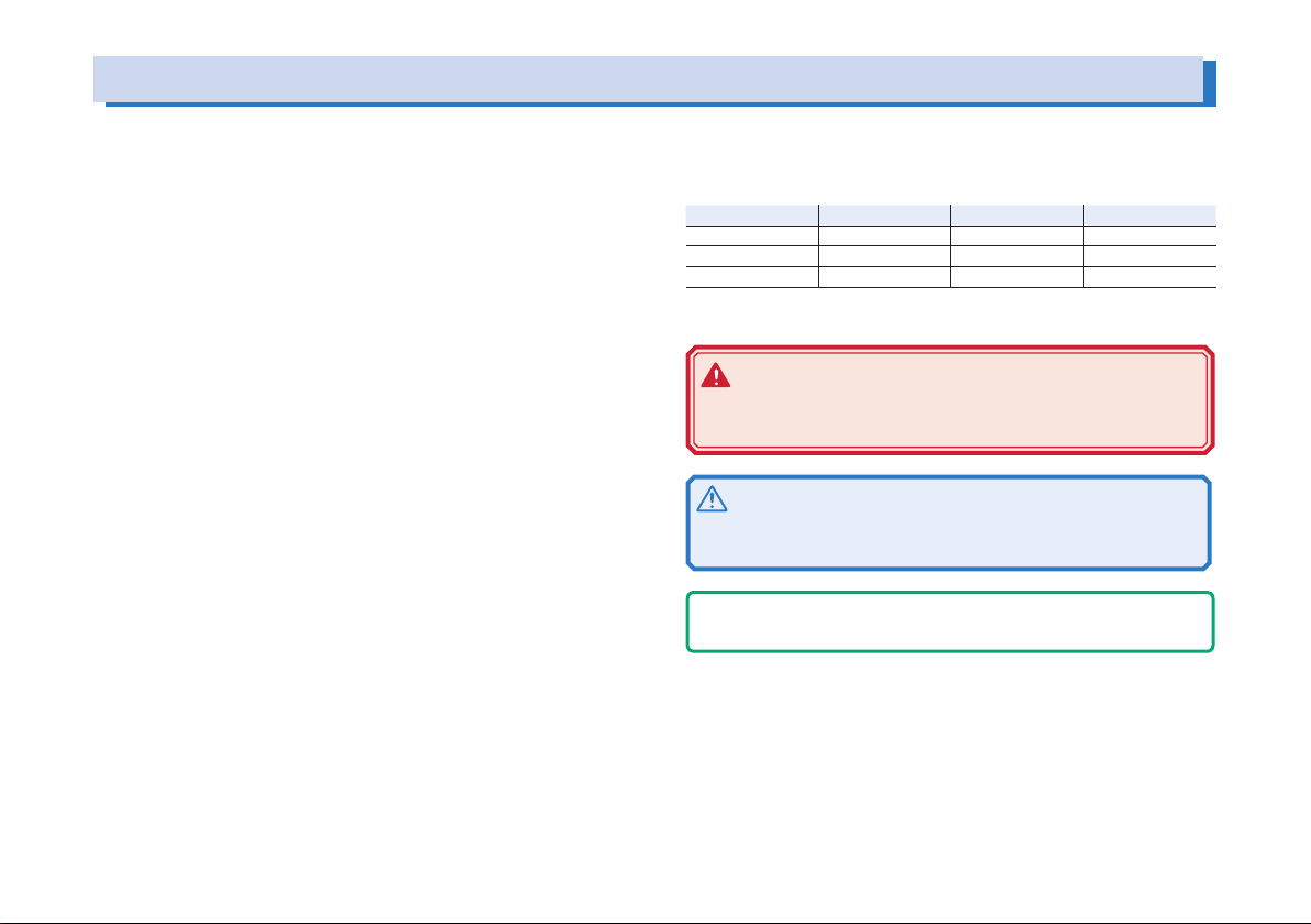
The PWR series is classified into three types depending on the output
capacity. It is also classified into three types depending on the output
voltage.
L type (80 V) M type (320 V) H type (650 V)
400W type PWR400L PWR400M PWR400H
800W type PWR800L PWR800M PWR800H
1600W type PWR1600L PWR1600M PWR1600H
The following markings are used in the explanations in the text.
WARNING
Indicates a potentially hazardous situation which, if ignored, could result in death or serious injury.
CAUTION
Indicates a potentially hazardous situation which, if ignored,
may result in damage to the product or other property.
- Note Indicates information that you should know.
SHIFT+switch name (marked in blue)
Indicates an operation in which a switch marked in blue is pressed
while holding down the SHIFT switch.
C-x: x
The first two characters “C-” indicate a configuration setting, and the
next one-digit number indicates the CONFIG parameter number. The
character after the colon indicates the selected setting.
PWR Series Setup Guide 3
L
M
H
Output voltage [V]
Output current [A]
Ambient temp. [°C]
Output current [%]
(
e
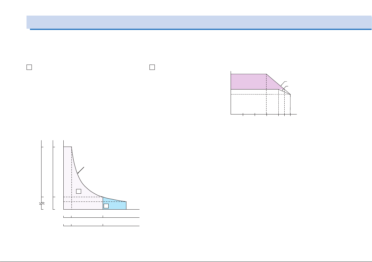
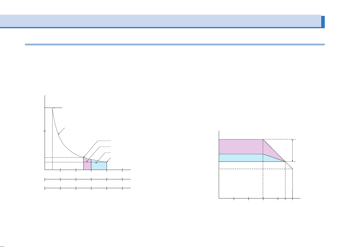
Description of Operation
The PWR is a constant voltage/current regulated DC power supply
that is capable of delivering voltages and currents in a wide operating range within the rated output power. Figure shows the operating area of the 400 W type.
A
the extended operating area. The extended operating area is valid
only on the L type.
If the PWR is configured in way that satisfies the equation output
voltage x output current ≤ rated output power, the PWR operates as
a conventional constant voltage/current power supply.
If the PWR is configured in a way that satisfies the equation output
voltage x output current > rated output voltage, the actual output is
limited by the power limit (approx. 105% of the rated output power)
and the output voltage or output current varies depending on the
load value.
4 PWR Series Setup Guide
in the figure indicates the rated operating area, and B indicates
320
650
PWR400H
PWR400M
80
Rated output poer (400W) line
PWR400L
A
16
64
200
0
10
0
0
50
0
1.25 6.25
0
0.615 2
type only
L
B
25 40
PWR400
PWR400
PWR400
The output current must be derated with respect to the temperature
at ambient temperatures greater than or equal to 45 ºC (30 ºC when
operating in the extended operating area) on the L type and 40 ºC
on the M/H type.
160
Rated output current)
100
Extended operating
area
80
Rated operating area
0
10 20 4530 40 50
L type
M/H typ
Extended operating area (L type only)
v
a
Ambient temperature [°C]
(Rated output current)
Extended
operating
Of the output current setting range of the PWR as illustrated in
figure below, the range between the rated output current and the
maximum output current (160 % of the rating) is the extended operating area. The specifications of load fluctuation, input fluctuation,
ripple/noise, and so on are not met in the extended operating area.
The extended operating area is divided into the continuous extended operating area and the intermittent extended operating area.
oltage [V]
Output
80
50
16
10
Rated output voltage
Rated output power line
Rated output current
Continuous extended operating area
Intermittent extended operating are
Maximum output current
Rated operating area
50 10 20 25 30 40 50
10 20 40 50 60 80 100
20 40 80 100 120 160 200
Extended
operating area
Output current [A]
PWR400L
PWR800L
PWR1600L
• Extended operating area
Continuous output is possible. At ambient temperatures greater
than or equal to 30 ºC, the output current must be derated with
respect to the temperature.
• Continuous extended operating area
The output duration is limited.
Guideline of the time duration of operation (When operating by
itself with no devices that generate heat around the PWR.)
Maximum Output Duration: 10 minutes
Pause Duration: At least twice the output duration
When using the PWR in the extended operating area, pay attention
to the ambient temperature, preset current, and output duration.
Output current [%]
160
Intermittent extended
operating area
120
Continuous extended operating area
100
80
Rated operating area
0 10 20 4530 40 50
area
PWR Series Setup Guide 5
Precautions Concerning Installation
4
Connecting the Power Cord
This product cannot be used while it is on its side.
The feet on the side panel of the 1600 W type are for temporarily
laying the unit on its side before carrying the unit by the handle.
Do not use or store the unit on its side as it may tip over.
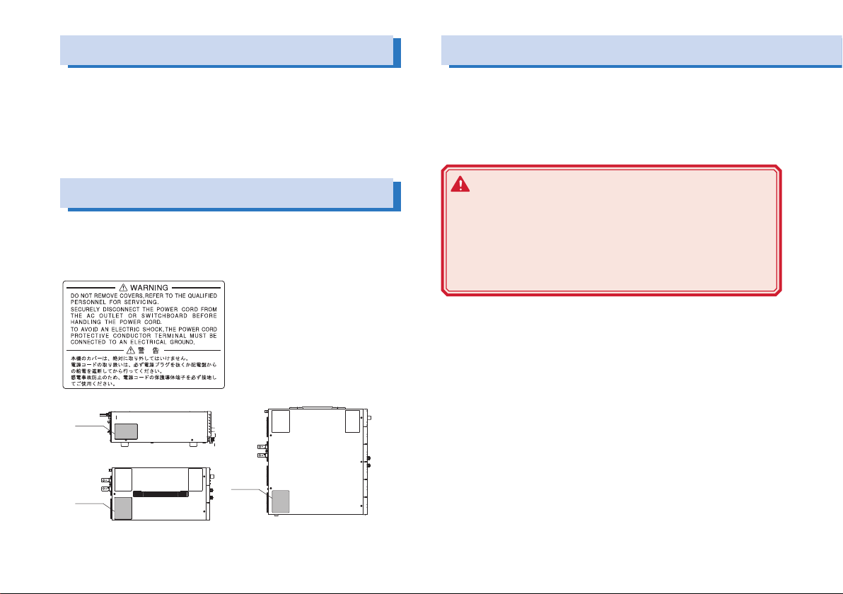
Safety Precautions
There is a warning label affixed to the product. If this label tears or
falls off, replace with a new label. If you need a new label, contact
your Kikusui agent or distributor.
The power cord provided with the PWR varies depending on the
output capacity type. For the procedure to connect the power cord,
see the respective section for each type. This product is designed
as an equipment of IEC Overvoltage Category II (energy-consuming
equipment supplied from the fixed installation).
WARNING
Possible electric shock.
• This product is an IEC Safety Class I equipment
(equipment with a protective conductor terminal). Be
sure to ground the product to prevent electric shock.
• Connect the ground terminal to earth ground.
00W type left side panel
Label
800W type top side panel
Label
1600W type top panel
Label
6 PWR Series Setup Guide
 Loading...