

Page 1
PART NO. IB024614
setting range
setting range
Feb . 2016
PMX Serie
s
Quick Reference
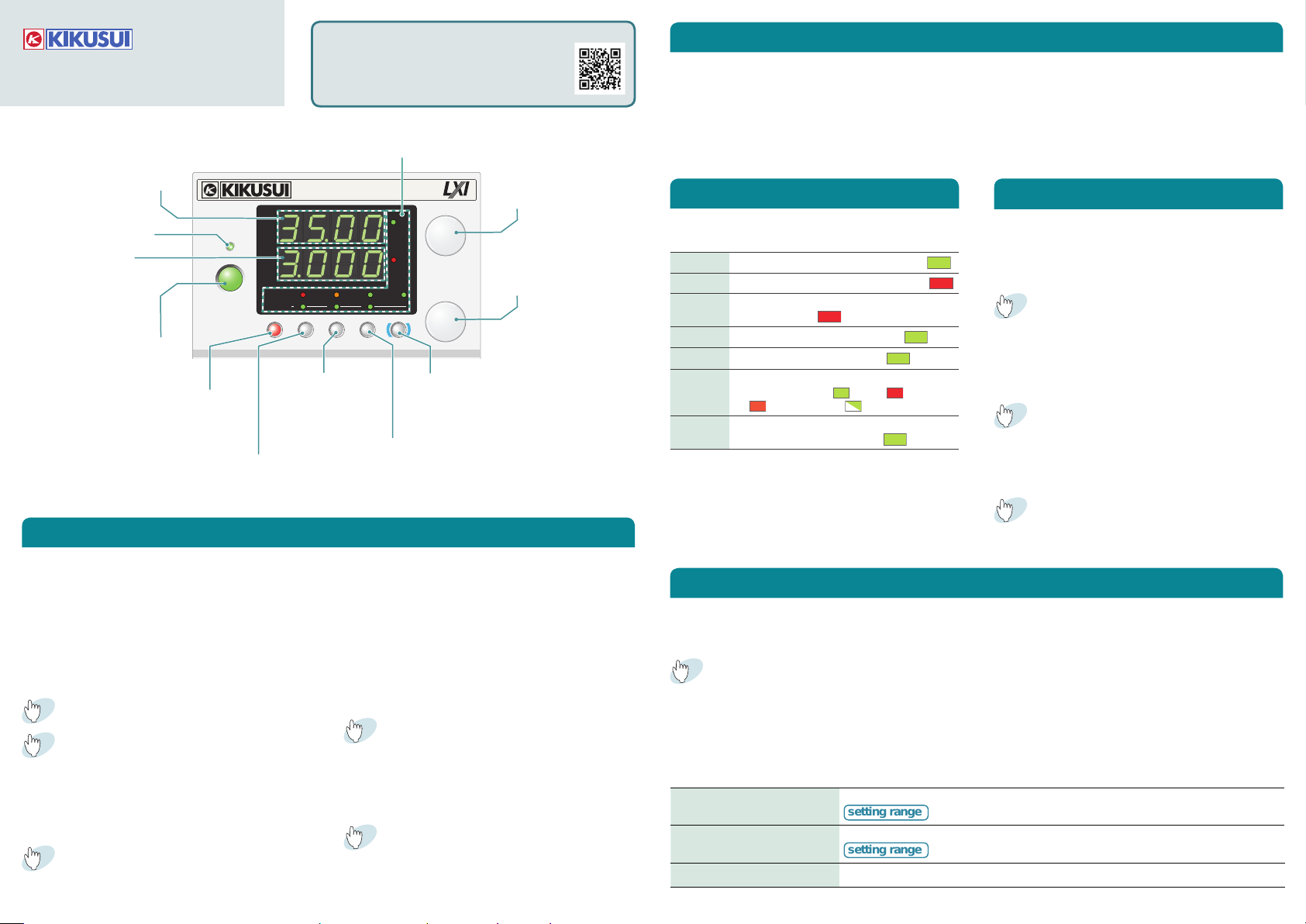
Voltmeter
Displays the voltage, value
of a CONFIG parameter,
cause of an alarm
OUT PUT LED
Lights when output is
turned on
Ammeter
Displays the current,
power, CONFIG
parameter
OUT PUT
Output on and off
SET/ ALM CLR
Set and confirm, release protection
functions that have been activated
OCP∙OVP/ A
Set and display the protection functions,
recall and save the preset memory A
OUTPUT
You can download the most recent manuals
from the following website.
http://www.kikusui.co.jp/en
Status indicators
REGULATED DC POWER SUPPLY
PMX35-3A
0-35V 3A
V
A
PRESET
SETLOCKCONFIG LOCAL
LANLOCKALARM
OVP࣭OCP
CONFIG/ B
Configure the
conditions, recall
and save the preset
memory B
REMOTE
BCA
CBASHIFTALM CLR
LOCK/ C
key lock, recall and save the
preset memory C
VOLTAGE/ FINE
Set the voltage value,
select the value of a
VOLTAGE
CV
CONFIG parameter
FINE
CURRENT/ FINE
CC
Set the current value,
change a parameter in the
CURRENT
CONFIG settings
FINE
LOCAL/ SHIFT
Switch remote mode, enable the functions
that are written in blue characters
Measured Value Display and Setting Display
• Measured value display
When the SET key LED is off, the present output
voltage and output current are displayed. You
can change the output voltage and output current while the measured value displayed.
• Setting display
Status indicators
LEDs light when the PMX is in the following states.
CV Lights during constant voltage mode
CC Lights during constant current mode
ALARM
LOCK Lights when the keys are locked
REMOTE Lights during remote control
LAN Lights and blinks when the LAN interface
PRESET
A, B, C
Lights when a protection function has
been activated
is in use ( No Fault
by
/ WEB Identify )
Lights when the memory A, B or C values
are being recalled or saved
/ Fault / Stand-
You can stores three sets (A, B or C) of the voltage
and the current.
Saving setting to preset memory
Recalling preset memory entries
Press SET to light its key and display the present
output voltage and output current settings.
Press SET again to return to the measured value
display.
Preset Memory Function
To save a preset mem or y, press SHI FT+the
memor y key (A , B, or C) to wh ich you wa nt
to save the s e tting s u ntil the ir LEDs turn on
(Hold the keys down).
1
Press SH IFT+the me mory k ey (A, B, or C)
from whi ch you want to re call the p reset
memory entry.
※ If you hold down, the present values in use will
be saved to the preset memory entry instead.
Panel Operations
Using the PWX as a CV or CC Power Supply
When the PWX is in CV mode, the set current is the
limit of the current that can flow through the load.
When the PWX is in CC mode, the set voltage is the
limit of the voltage that can applied to the load. If the
limit is reached, the PWX automatically switches the
CV/ CC mode.
Press SET to change to the setting display.
1
Turn the VOLTAGE knob to se t the volt age,
2
Turn the CURRENT knob to set the current.
Voltage range: 0 % to 105 % of the rated output
voltage
Current range: 0 % to 105 % of the rated output
current
Press OUTPUT to turn output on.
3
The output turns on and off each time you press
OUTPUT.
Locking Panel Operations (Key lock)
When the keys are locked, the key and rotary knob
is invalid. There are three levels of key lock. Use
CONFIG parameter CF03 to set the level.
● Loc1: Lock all keys except the OU TPUT and
memory A, B, and C keys.
● Loc2: Lock all keys except the OUTPUT key
● Loc3: Lock all keys and the rotary knob.
Hold dow n LOCK key until t he LOCK LED
light s. To unloc k th e keys, h ol d dow n LOCK
key again until the LOCK LED turns off.
To set the PWX to the Factory Default
Hold dow n LO C K+LOCAL w h i l e yo u t u rn the
POWER switch on.
2
Check th e displayed se ttings, a nd then
press SET.
Protection Functions
The PMX is equipped with the following protection functions. When a protection function is activated, an alarm
occurs, the output is turned off, and the cause of the alarm is indicated.
Press OCP • OVP key for setting the OVP trip point, the OCP trip point.
There are two methods to clear alarm.
● Press ALM CLR (SHIFT+SET)
● Turn the PMX off, fix the problem that caused the alarm, and then turn the PMX on.
Unless you fix the problem that caused the alarm to occur, the alarm will occur again.
Overvoltage protection (OVP) Activated when the output terminal voltage exceeds the set voltage (OVP trip point).
Overcurrent protection (OCP) Activated when the output current exceeds the set current (OCP trip point).
Overheat protection (OHP) Activated when the internal temperature rises to an abnormal level.
10 % to 110 % of the rated output voltage
10 % to 110 % of the rated output current
Page 2
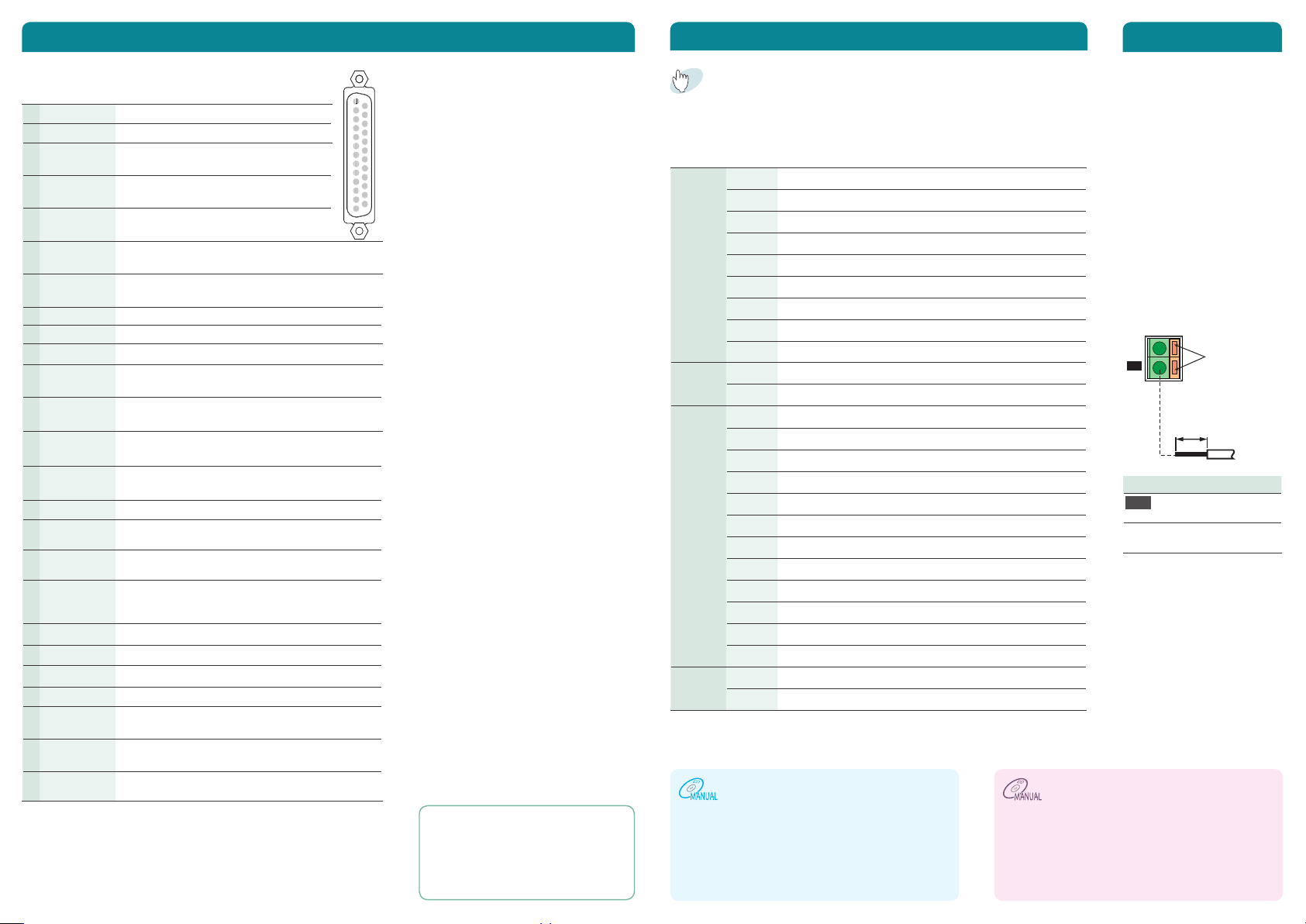
External Control
134
5
6
7
8
9
10
11
12
14
15
16
17
18
19
20
21
22
23
25
Insert the wire
CONFIG Settings
Sensing
You can use the J1 connector of external control.
1 VMON Output voltage monitor.
2 IMON Output current monitor.
3 A COM External signal common for pins 1, 2, 4,
4 EXT-V CV
CONT
5 A COM External signal common for pins 1, 2, 4,
6 EXT-R CV
CONT
7 EXT-R CV
CONT COM
*1
and 14.
Used to control the output voltage with
an external voltage
*1
and 14.
Used to control the output voltage with an external
resistance.
Used to control the output voltage with an external resistance.
1
14
2
15
3
16
4
17
5
18
6
19
7
20
8
21
9
22
10
23
11
24
12
25
13
8 N.C Not connected.
9 N.C Not connected.
10 N.C Not connected.
11 CV STATUS On when the PWX is in CV mode.
Photocoupler open collector output.
12 CC STATUS On when the PWX is in CC mode.
Photocoupler open collector output.
13 ALM STATUS On when a protection function has been activated.
Photocoupler open collector output.
14 EXT-V CC
CONT
15 A COM
16 EXT-R CC
CONT
17 EXT-R CC
CONT COM
18 OUT ON/OFF
CONT
Used to control the output current with an external
voltage.
External signal common for pins 1, 2, 4, and 14.
Used to control the output current with an external
resistance.
Used to control the output current with an external
resistance.
Output on/off control terminal.
The output can be turned on and off using external contact input.
19 D COM
External signal common for pins 18.
*2
*2
*2
*1
20 N.C Not connected.
21 N.C Not connected.
22 N.C Not connected.
23 OUT ON
STATUS
24 PWR ON
STATUS
On when the output is on.
Photocoupler open collector output.
On when the power is on.
Photocoupler open collector output.
*2
*2
25 STATUS COM Status signals common for pins 11, 12, 13, 23 and
24.
*1. During remote sensing, this is the negative (-S) of sensing input. When
remote sensing is not being performed, this is connected to the negative
output.
*2. Open collector output: Max. voltage of 30 V and max. current of 8 mA.
The status common is floating (isolation voltage or less), it is isolated
from the control circuit.
Output voltage control
Set the CV control using an external
voltage or an external resistance in
the CONFIG settings so that external
voltage control is enabled (CF05:VoLt/
rES).
• Control using an external voltage
(Vext)
Use pins : 4, 5
• Control using an external resis
-
tance (Rext)
Use pins : 6, 7
Output current control
Set the CC control using an external
voltage or an external resistance in
the CONFIG settings so that external
voltage control is enabled (CF04:VoLt/
rES).
• Control using an external voltage
(Vext)
Use pins : 14, 15
• Control using an external resis-
*1
tance (Rext)
Use pins : 16, 17
Output on and off control
To use an external contact to control
the output on and off states, set the
appropriate CONFIG parameter (CF06:
on)
Use pins : 18, 19
External monitoring
• External monitoring of the output
voltage and output current status
Use pins : 1, 2, 3, 5, 15
Press CONFIG and use the VOLTAGE knob to select the parameter
that you want to set, and the CURRENT knob to change its value.
: Indicates a parameter that is applied immediately.
r
: Indicates a parameter that is applied when the PMX is turned on.
¯
: Indicates a parameter that is applied when CF34 is executed.
SYSTEM CF00
CF01
CF02
CF03
CF04
CF05
CF06
CF07
CF08
INTER
FACE
CF20
CF21
LAN CF30
CF31
CF32
CF33
CF34
CF35
CF36
CF37
CF38
CF39
CF40
CF41
USB CF50
CF51
*1. This parameter affects the PWX when the panel settings are reset (CF00).
*2. The item can be configured only when the output is off.
Resets the panel settings
Power-on output status
Memory content display
Key lock
*1, *2
CC control using an Vext or Rext
1, *2
*
CV control using an Vext or Rext
1, *2
*
External control for turning output on and off
*2
External control logic for turning output on and off
Output-on startup state parameter
Remote interface
SCPI communication error display
DHCP
AUTO IP address
MANUAL IP address
Resets the LAN interface settings (LCI)
Restarts the LAN interface (REBOOT)
IP address display (1)
IP address display (2)
IP address display (3)
IP address display (4)
MAC address display (1) and (2)
MAC address display (3) and (4)
MAC address display (5) and (6)
VID (vendor ID) display
PID (product ID) display
r
r
¯
r
or
¯
r
or
¯
r
or
─
─
─
─
─
─
─
─
─
• Local sensing
This method when the
load current is small or
when you do not need to
consider the load effect
voltage.
• Remote sensing
This is a feature that stabilizes the output voltage
across the load by reducing the influence of voltage drops and other effects caused by the load
cable resistance.
+
S
-
S
while holding
down this
section with a
screwdriver.
STRIP-GAUGE
7mm
AWG20-14
Terminal Function
-S
Negative remote
sensing terminal
+S Positive remote
sensing terminal
• External monitoring of the status
Use pins : 11, 12, 13, 23, 24, 25
For Rext, use a resistor that is rated
at approx. 10k Ω , 1/2 W or greater,
that has a low temperature coefficient,
and that will change little over time.
Examples of such resistors are metal
film or wire wound resistors.
The "User's Manual" (included CD-ROM) describes the following information.
●
Mounting to a Rack
●
Connecting to the Output Terminals
●
Options ●Calibration ● Troubleshooting
RS232C, USB, and LAN interfaces (LXI) are all
installed as standard with a Communication feature. For information about the remote control,
see the "Communication interface manual" (included CD-ROM).
 Loading...