

Kikusui PMC18-2A, PMC35-1A, PMC18-3A, PMC35-0.5A, PMC35-2A Operation Manual
...
Part No. Z1-004-632, IA004571
Jun. 2009
OPERATION MANUAL
REGULATED DC POWER SUPPLY
PMC-A SERIES
TYPE I
PMC 18-1A
PMC 18-2A
PMC 18-3A
TYPE II
PMC 18-5A
PMC 35-3A
PMC 70-1A
PMC 110-0.6A
PMC 35-0.5A
PMC 35-1A
PMC 35-2A
PMC 160-0.4A
PMC 250-0.25A
PMC 350-0.2A
PMC 500-0.1A

Use of Operation Manual
Please read through and understand this Operation Manual before operating
the product. After reading, always keep the manual nearby so that you may
refer to it as needed.
If you find any misplaced or missing pages in this manual, they will be
replaced. If the manual gets lost or soiled, a new copy can be provided for a
fee. In either case, please contact Kikusui distributor/agent, and provide the
“Kikusui Part No.” given on the cover.
This manual has been prepared with the utmost care; however, if you have
any questions, or note any errors or omissions, please contact Kikusui dis
tributor/agent.
-
Reproduction and reprinting of this operation manual, in whole or in part,
without written permission is prohibited.
Both unit specifications and manual contents are subject to change without
notice.
Copyright© 2009 Kikusui Electronics Corporation
2 PMC-A

Power Requirements of this Product
✓
WARNING
Power requirements of this product have been changed and relevant sections
of the Operation Manual should be revised accordingly. (Revision should be
applied to items indicated by a check mark .)
Input voltage
The input voltage of this product is Vac,
and the voltage range is to Vac. Use the product
within this range only.
Input fuse
The rating of this product’s input fuse is A, Va c ,
and .
• To avoid electrical shock, always disconnect the
power cord or turn off the switchboard before
attempting to check or replace the fuse.
• Use a fuse element having a shape, rating, and
characteristics suitable for this product. The use of a
fuse with a different rating or one that short circuits
the fuse holder may result in fire, electric shock, or
irreparable damage.
PMC-A 3

4 PMC-A
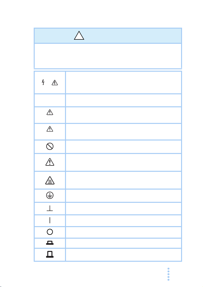
Safety Symbols
!
For the safe use and safe maintenance of this product, the following
symbols are used throughout this manual and on the product. Note the
meaning of each of the symbols to ensure safe use of the product. (Not
all symbols may be used.)
Indicates that a high voltage (over 1 000 V) is used here.
or
To uching the part causes a possibly fatal electric shock. If physical contact is required by your work, star t work only after you
make sure that no voltage is output here.
DANGER
WAR N ING
CAUTION
Indicates an imminently hazardous situation which, if ignored,
will result in death or serious injury.
Indicates a potentially hazardous situation which, if ignored,
could result in death or serious injury.
Indicates a potentially hazardous situation which, if ignored, may
result in damage to the product and other property.
Shows that the act indicated is prohibited.
Indicates a general danger, warning, or caution.
When this symbol is marked on the product, see the relevant
sections in this manual.
Indicates a caution for hot surface of the product.
When this symbol is marked on the product, see the relevant
sections in this manual.
Protective conductor terminal.
Chassis (frame) terminal.
On (supply)
Off (supply)
In position of a bi-stable push control
Out position of a bi-stable push control
PMC-A 5
Safety Precautions
!
Line
Voltage
The following safety precautions must be observed to avoid fire hazards,
electric shock, accidents, and other failures. Keep them in mind and make
sure to observe them.
Using the product in a manner that is not specified in this manual may
impair the protection functions provided by the product.
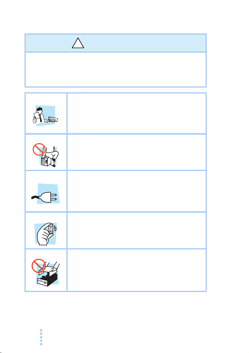
Users
n
o
i
t
ra
e
p
O
Manual
Purpose of use
Input power
Fuse
Cover
• This product must be used only by qualified personnel who
understand the contents of this operation manual.
•If unqualified personnel is to use the product, be sure the
product is handled under the supervision of qualified
personnel (those who have electrical knowledge). This is to
prevent the possibility of personal injury.
• Never use the product for purposes other than the product's
intended use.
• This product is not designed or manufactured for general
home or consumer use.
• Use the product within the rated input power voltage range.
• For applying power, use the power cord provided. For
details, see the respective page in the operation manual.
• This product is designed as an equipment of IEC
Overvoltage Category II (energy-consuming equipment
supplied from the fixed installation).
•The fuse can be replaced with a new one. When replacing a
fuse, use the one which has appropriate shape, ratings, and
specifications. For details, refer to the specification section in
this manual.
• Some parts inside the product may cause physical hazards.
Do not remove the external cover.
• When the product is under the operation, the surface of top
cover may get high temperature. It may cause burn on the
skin.
6 PMC-A
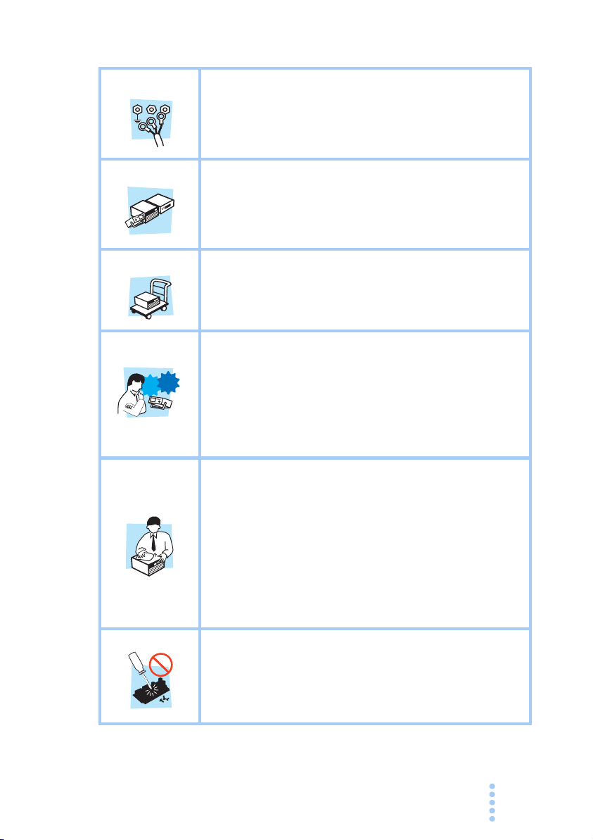
Grounding
Check?
N
G
• This product is an IEC Safety Class I equipment (equipment
L
with a protective conductor terminal). To prevent the
possibility of electric shock, be sure to connect the protective
conductor terminal of the product to electrical ground (safety
ground).
Installation
Relocation
Operation
Maintenance
and
inspection
• This product is designed for safe indoor use. Be sure to use
it indoors.
• When installing this product, be sure to observe the
description in 2.2 Precautions Concerning Installation
Location in this manual.
•Turn off the POWER switch, and disconnect all cables
before relocating the product.
• When relocating the product, be sure to include the manual.
•If a malfunction or abnormality is detected on the product,
stop using it immediately, and remove the power plug from
the outlet. Make sure the product is not used until it is
completely repaired.
• Use cables or wires with sufficiently large current capacity
for output wires and load cables.
• Do not disassemble or modify the product. If you need to
modify the product, contact your Kikusui distributor/agent.
• To prevent the possibility of electric shock, make sure to
unplug the power plug before carrying out maintenance or
inspection. Do not remove the external cover during
maintenance or inspection.
• Check that the insulation coating of the power cord is not
broken and that the plug is not cracked or falling apart.
• If the panel needs cleaning, gently wipe using a soft cloth
with water-diluted neutral detergent.
• To maintain the performance and safe operation of the
product, it is recommended that periodic maintenance,
inspection, cleaning, and calibration be performed.
Service
PMC-A 7
•Kikusui service engineers will perform internal service on the
product. If the product needs adjustment or repairs, contact
your Kikusui distributor/agent.

How to Read This Manual
Preface
Thank you for purchasing the PMC-A Series regulated DC
power supply.
This manual is intended for first-time users of the PMC-A
Series (hereafter abbreviated as: the PMC-A). It gives an
overview of the PM
operation, maintenance, safety precautions, etc.
Read this manual thoroughly to use the functions of the PMC-A
effectively. You can also review this manual; when you are
confused about an operation or when a problem occurs.
How to read this manual
This manual is designed to be read from beginning to end. We
recommend that you read the manual thoroughly from the
beginning before using the PMC-A for the first time.
Intended readers of this manual
This manual is intended for those using the PMC-A of
regulated DC power supply and teaching other users on how to
operate the PMC-A.
It assumes that the reader has knowledge of a regulated DC
power
.
C-A and describes various settings,
8 PMC-A
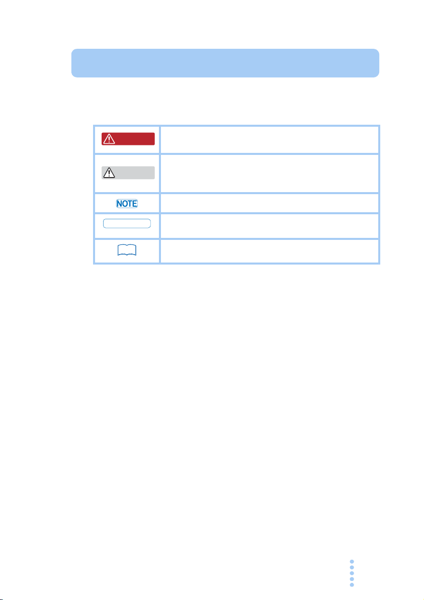
Notations used in this manual
WARNING
CAUTION
DESCRIPTION
See
The following marks are used with the corresponding
explanations in this manual.
Indicates an imminently hazardous situation which, if
ignored, could result in death or serious injury.
Indicates a potentially hazardous situation which, if
ignored, may result in damage to the product and other
property.
Indicates information that you should know.
Explanation of terminology or operation principle.
Indicates reference to detailed information.
PMC-A 9

Contents
Contents
Safety Symbols - - - - - - - - - - - - - - - - - - - - - - - - - - - - - - - - - - -5
Safety Precautions - - - - - - - - - - - - - - - - - - - - - - - - - - - - - - - - -6
How to Read This Manual - - - - - - - - - - - - - - - - - - - - - - - - - - - -8
Contents - - - - - - - - - - - - - - - - - - - - - - - - - - - - - - - - - - - - - - -10
Function index - - - - - - - - - - - - - - - - - - - - - - - - - - - - - - - - - - -13
Front panel - - - - - - - - - - - - - - - - - - - - - - - - - - - - - - - - - - - - -14
Rear Panel - - - - - - - - - - - - - - - - - - - - - - - - - - - - - - - - - - - - -16
Chapter 1 General Description
1.1 About This Manual - - - - - - - - - - - - - - - - - - - - - - - - - - - -17
1.2 Product Overview - - - - - - - - - - - - - - - - - - - - - - - - - - - - -17
1.3 Features - - - - - - - - - - - - - - - - - - - - - - - - - - - - - - - - - - -18
1.4 Options - - - - - - - - - - - - - - - - - - - - - - - - - - - - - - - - - - - -19
Chapter 2 Installation and Preparation
2.1 Checking the Package Contents - - - - - - - - - - - - - - - - - -23
2.2 Precautions Concerning Installation Location - - - - - - - - -24
2.3 Precautions to Be Taken When Moving the Product - - - -26
2.4 Rack-mount Adaptor Installation - - - - - - - - - - - - - - - - - -26
2.5 Connecting the Power Cord - - - - - - - - - - - - - - - - - - - - -27
2.6 Ground (Earth) - - - - - - - - - - - - - - - - - - - - - - - - - - - - - - -28
2.7 Turning On the Power - - - - - - - - - - - - - - - - - - - - - - - - -29
Inrush Current - - - - - - - - - - - - - - - - - - - - - - - - - - - - - -30
Reverse Polarity - - - - - - - - - - - - - - - - - - - - - - - - - - - -30
Chapter 3 Connecting the Load
3.1 Load Considerations - - - - - - - - - - - - - - - - - - - - - - - - - -31
3.1.1 When the Load Current Has Peaks or is Pulse-shaped
- - - - - - - - - - - - - - - - - - - - - - - - - - - - - - - - - - - - - -31
3.1.2 When the Load Generates a Reverse Current to the
Power Supply - - - - - - - - - - - - - - - - - - - - - - - - - - - -32
3.1.3 When the Load Has Accumulated Energy Such As
Batteries - - - - - - - - - - - - - - - - - - - - - - - - - - - - - - -32
3.2 Connecting the Load - - - - - - - - - - - - - - - - - - - - - - - - - -33
3.2.1 Load Cable - - - - - - - - - - - - - - - - - - - - - - - - - - - - -34
Current capacity of the load cable - - - - - - - - - - - - - - - -34
10 PMC-A

Contents
Dependence of allowable cable current on the maximum
allowable insulator temperature - - - - - - - - - - - - - - - - -34
Taking measures against noise - - - - - - - - - - - - - - - - - -35
Voltage rating of the load cable - - - - - - - - - - - - - - - - - -35
3.2.2 Connecting to the Output Terminal - - - - - - - - - - - - -35
Chapter 4 Basic Operation
4.1 Constant Voltage (CV) and Constant Current (CC) Power
Supplies - - - - - - - - - - - - - - - - - - - - - - - - - - - - - - - - - - - 37
Crossover point - - - - - - - - - - - - - - - - - - - - - - - - - - - - - 39
Example of CV/CC mode operation - - - - - - - - - - - - - - -39
4.2 Using the Power Supply as a Constant Voltage Power Supply
- - - - - - - - - - - - - - - - - - - - - - - - - - - - - - - - - - - - - - - - - -40
Output Setup Procedure - - - - - - - - - - - - - - - - - - - - - - -40
4.3 Using the Power Supply as a Constant Current Power Supply
- - - - - - - - - - - - - - - - - - - - - - - - - - - - - - - - - - - - - - - - - - 40
Output Setup Procedure - - - - - - - - - - - - - - - - - - - - - - -40
4.4 Protection Function - - - - - - - - - - - - - - - - - - - - - - - - - - - 41
4.4.1 Overvoltage Protection (OVP) Function - - - - - - - - -41
Setup procedure of the OVP trip point - - - - - - - - - - - - -41
Clearing alarms - - - - - - - - - - - - - - - - - - - - - - - - - - - - -42
4.4.2 Overheat Protection (OHP) Function - - - - - - - - - - -42
4.4.3 Other Protection Functions - - - - - - - - - - - - - - - - - -42
4.5 Remote Sensing - - - - - - - - - - - - - - - - - - - - - - - - - - - - -43
Handling of SENSING terminals - - - - - - - - - - - - - - - - -43
Connection and setup procedure - - - - - - - - - - - - - - - -44
4.6 Master-Slave Parallel Operation - - - - - - - - - - - - - - - - - - 45
Handling of J1 Terminal - - - - - - - - - - - - - - - - - - - - - - -45
4.6.1 Functions during Master-Slave Parallel Operation - -46
Connection and setup procedure - - - - - - - - - - - - - - - -47
Starting and ending parallel operation - - - - - - - - - - - - -48
4.7 Series Operation - - - - - - - - - - - - - - - - - - - - - - - - - - - - - 51
Maximum number of power supplies connected in series -
- - - - - - - - - - - - - - - - - - - - - - - - - - - - - - - - - - - - - -52
4.7.1 Functions during Series operation - - - - - - - - - - - - -52
Connection and setup proced
Starting and ending series operation - - - - - - - - - - - - - -53
ure - - - - - - - - - - - - - - - -53
Chapter 5 External Control
5.1 External Remote Control - - - - - - - - - - - - - - - - - - - - - - -55
PMC-A 11

Contents
J2 connector - - - - - - - - - - - - - - - - - - - - - - - - - - - - - - -56
5.1.1 Remote Control Connection and Setup - - - - - - - - - -59
Controlling the output voltage using external voltage - - -60
Controlling the output voltage using external resistance -61
Controlling the output current using external voltage - - -61
Controlling the output current using external resistance -62
Output on/off control - - - - - - - - - - - - - - - - - - - - - - - - - -63
5.2 Remote Monitoring - - - - - - - - - - - - - - - - - - - - - - - - - - - -63
5.2.1 External Monitoring of the Output Voltage and Output
Current. - - - - - - - - - - - - - - - - - - - - - - - - - - - - - - - -63
5.2.2 External monitoring of the operating status - - - - - - -64
Chapter 6 Maintenance
6.1 Replacing the Fuse - - - - - - - - - - - - - - - - - - - - - - - - - - -66
6.2 Calibration - - - - - - - - - - - - - - - - - - - - - - - - - - - - - - - - - -67
Test equipment required for calibration - - - - - - - - - - - -67
Environment - - - - - - - - - - - - - - - - - - - - - - - - - - - - - - -67
Calibration Procedure - - - - - - - - - - - - - - - - - - - - - - - - -67
Voltage system calibration procedure - - - - - - - - - - - - -68
Current system calibration procedure - - - - - - - - - - - - - -71
Chapter 7 Specifications
7.1 Specifications (Type I) - - - - - - - - - - - - - - - - - - - - - - - - -75
7.2 Specifications (Type II) - - - - - - - - - - - - - - - - - - - - - - - - -80
7.3 Dimension Diagram - - - - - - - - - - - - - - - - - - - - - - - - - - -85
12 PMC-A
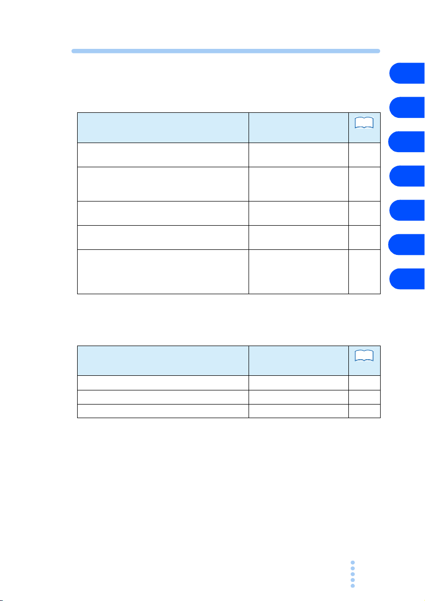
Function index
See
See
Preparation
Usage scenarios Manual sections
Confirming accessories 2 Installation and
Rated input values - quantities 2.5 Connecting the Power
What may be used with power supply
connected to load
Precautions for connecting to remote sensing
lines
Necessary preparations for rack mounting 1.4 Options
Preparation
Cord
7 Specifications
3.2 Connecting the Load
4.5 Remote Sensing
2.4 Rack-mount Adaptor
Installation
7 Specifications
Use
page
23
27
74
34
43
19
26
74
1
2
3
4
5
6
7
Usage scenarios Manual sections
Learning protection details 4.4 Protection Function 41
Learning available function 1.3 Features 18
Clearing alarm conditions immediately. 4.4 Protection Function 41
PMC-A 13
page
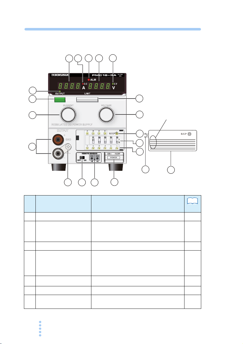
Front panel
1
11
2
3
4
5
6
7
8
9
10
12
13
14
15
16
17
18
19
㧖
275*275*
Press this indicated area
toQRGPVJGEQXGT
No.
1 POWER switch
2 OUTPUT switch
Name Description
Depressed position is ON
Depressed position is ON. When this switch
is turned OFF, the OUTPUT of the power
supply is at high impedance (several k
3 OUTPUT LED
4 LIMIT switch
Lights when the output is ON. (Green)
The voltage and current settings are displayed while this switch is held down.
Ω).
This switch only displays the current setting.
It is not a memory function.
Vol tm eter Displays the voltage.
5
6 Ammeter
7 C.V LED
14 PMC-A
Displays the current.
Lights when operating in constant voltage
(CV) mode. (Green)
See
page
29
40
−
40
−
−
40

No.
See
8 C.C LED
9 VOLTAGE knob
10 CURRENT knob
11 OUTPUT terminal
12 GND terminal
SENSING terminal *1 Remote sensing terminal. 43
13
SENSING switch *1 Enables remote sensing. Turn off the switch
14
15 OVP variable resistor
ALM LED Lights when the overvoltage or overheat
16
S1 to S4 switches Used for analog remote control.
17
S5 switch Used for master-slave parallel control.
Variable resistor for cali-
18
bration
19 Front sub-panel cover
Name Description
Lights when operating in constant current
(CC) mode. (Red)
Sets the output voltage. (10 turns)
Sets the output current. (10 turns)
Red : + (positive) terminal
White : - (negative) terminal
Connect either output terminal to the GND
terminal using the short bar unless your
application requires the power supply output
to be floating.
Since Type II models use a relay switch
system, a relay switch noise may appear at
the rising edge of the output when the input
voltage is low or depending on the load
condition.
Connected to the chassis of the power sup-
ply.
when you are not using remote sensing.
Sets the OVP (Overvoltage Protection) trip
point.
protection circuit strips entering an alarm
status. (Red)
Used to calibrate the output voltage and the
meter.
To open the cover, press the part indicated
as PUSH. You can remove the cover by pull
ing the opened cover. Even if the claw (indi-
cated with ) breaks, the cover can be
attached without problem.
㧖
page
40
−
−
2
3
4
1
35
5
6
−
43
41
41
56
67
-
−
7
*1 Not available on models with rated output of 70 V or higher.
PMC-A 15
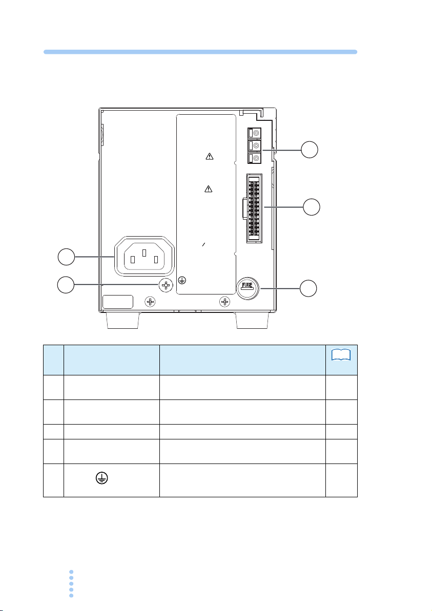
Rear Panel
J
1
J
2
KIKUSUI
ELECTRONICS
CORP.
WARNING
FOR CONTINUED
PROTECTION AGAINST
FIRE HAZARD,
REPLACE ONLY WITH
SAME TYPE AND
RATING FUSE.
CAUTION
TO AVOID ELECTRIC
SHOCK, THE AC POWER
CABLE PROTECTIVE
GROUNDING CONDUCTOR
MUST BE CONNECTED
TO GROUND. DO NOT
REMOVE COVERS,
REFER SERVICING TO
QUALIFIED PERSONNEL.
INPUT
AC100V 50 60Hz
MAX280VA
MADE IN CHINA
FUSE
AC250V
4A (S.B
)
1
2
3
1
2
3
4
5
No.
Name Description
See
page
J1 connector Input/output terminals for master slave par-
1
J2 connector Terminals for analog remote control and
2
Fuse holder Contains an AC input fuse (S.B type) 66
3
INPUT connector Power cord connector for supplying power
4
5
allel operation.
monitoring function.
to the power supply.
Protective conductor terminal.
Always ground the power supply.
43
45
56
27
28
16 PMC-A

General Description
1
This chapter gives an overview and introduces the features of
the PMC-A Series.
1.1 About This Manual
The PMC-A series come in two types depending on the size of
case. This operation manual describes the following models.
■ Type I
PMC18-1A, PMC18-2A, PMC18-3A, PMC35-0.5A,
PMC35-1A, PMC35-2A
■ Type II
PMC18-5A, PMC35-3A, PMC70-1A, PMC110-0.6A,
PMC160-0.4A, PMC250-0.25A, PMC350-0.2A,
PMC500-0.1A
1.2 Product Overview
The PMC-A Series are compact, high-performance, constant
voltage, constant current Series regulated DC power supplies.
The adoption of Series regulated design realizes a highly stable
output with a low level of output noise. In addition, with an
optional power supply controller, it allows to operate via GPIB
systems which offers wide application in the field of R&D,
Manufacturing, Testing, etc.
PMC-A 17

1.3 Features
● Digital display on both voltage and current at the same
time.
The PMC-A series power supply has two bright LED meters
that display the output voltage, output current, and their set
tings.
● High-resolution setting for output voltage and current.
The variable resistors for the output voltage and current set-
tings are 10-turn wire wound type, allowing high-resolution
settings.
● Output ON/OFF by external contact
The output ON/OFF switch is an electronic switch that emits
no chattering or noise. The switch can also be controlled
remotely.
● External Remote Control
The output voltage and current can be controlled remotely
using an external analog signal (voltage or resistance). By
connecting a power supply controller such as KIKUSUI's
PIA3200 or PIA4810 via the GPIB interface, the PMC-A
series power supply can be integrated into a system such as
an automated test system.
-
● External monitor function
The monitor output enables to monitor the status output, out-
put voltage, and output current from outside of the PMC-A.
● Remote sensing function
The remote sensing function stabilizes the output voltage
across the load. (equipped with 18 V, 35 V models)
● Equipped with overvoltage protection (OVP) function
as standard.
• To control the PMC-A series power supply using
KIKUSUI's PIA3200 (via the GPIB interface), the ROM
version of the PIA3200 must be 1.03 or later. If not, the
18 PMC-A

ROM needs to be upgraded. To have the ROM upgraded,
contact your Kikusui agent or distributor.
• On Type II models, the internal loss is decreased by
changing the input voltage of the series regulator. The
input voltage is changed by switching secondary taps of
the internal transformer using relays. The relay has three
switch points and changes depending on the input volt
age. If the input voltage fluctuates when the output volt-
age of power supply is used near a relay switch point, you
may hear the sound of the relay switching. This is not a
malfunction. When the relay is switched, a spike volt
age at the output voltage may be generated.
1.4 Options
The following options are available for the PMC-A series.
For details, contact your Kikusui agent or distributor.
■ Guard cap (GP01-PMC)
-
-
Exchanged with the knob to prevent inadvertent
operation of voltage or current setting.
1
General Description
■ Output terminal cover (OTC01-PMC)
Covers the output terminal to prevent unex-
pected accidents. Applies to models with a
rated output of 70 V or greater.
It is recommended that you use the output ter-
minal cover for your safety.
PMC-A 19
■ Handle (CH01-PMC)
A convenient handle for carrying the
power supply.
Applies to all type II models.
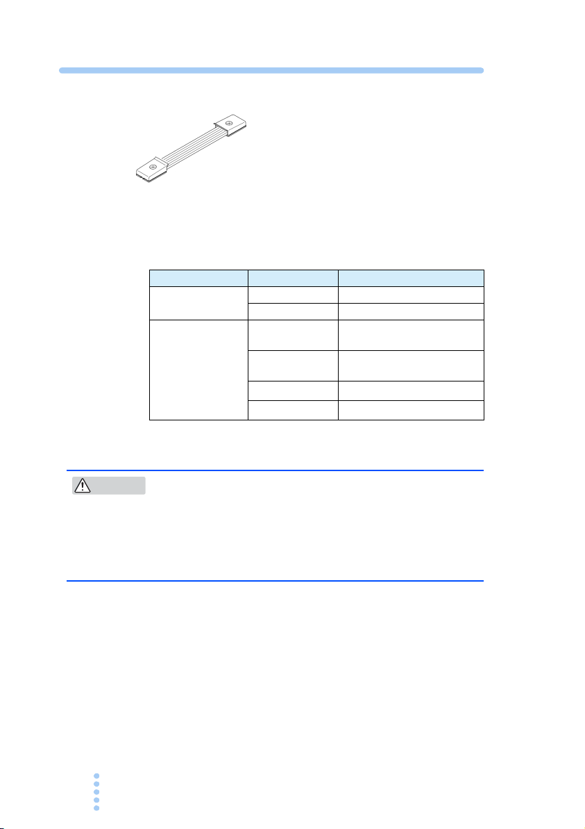
■ Rack mount options
The following options are available for rack mount system.
Name Model Note
Rack adapter
Blank panel
KRA3 inch rack (EIA standard)
KRA150 Milli rack (JIS standard)
KBP3-2
KBP3-4
BP191(-M)
BP1H(-M)
*1
(EIA, JIS common) - 1/2
width
(EIA, JIS common) - 1/4
width
*1
inch rack (EIA standard)
Milli rack (JIS standard)
*1. the model added with “-M” is “mesh” type.
CAUTION
• The PMC-A power supply uses unforced air cooling.
In order to keep a space for cooling intake, at least
one layer of “blank panel” must be installed when
the PMC-A is rack mounted.
JIS standard:50 mm、EIA standard:44.45 mm
*
For details, contact your Kikusui agent or distributor.
20 PMC-A
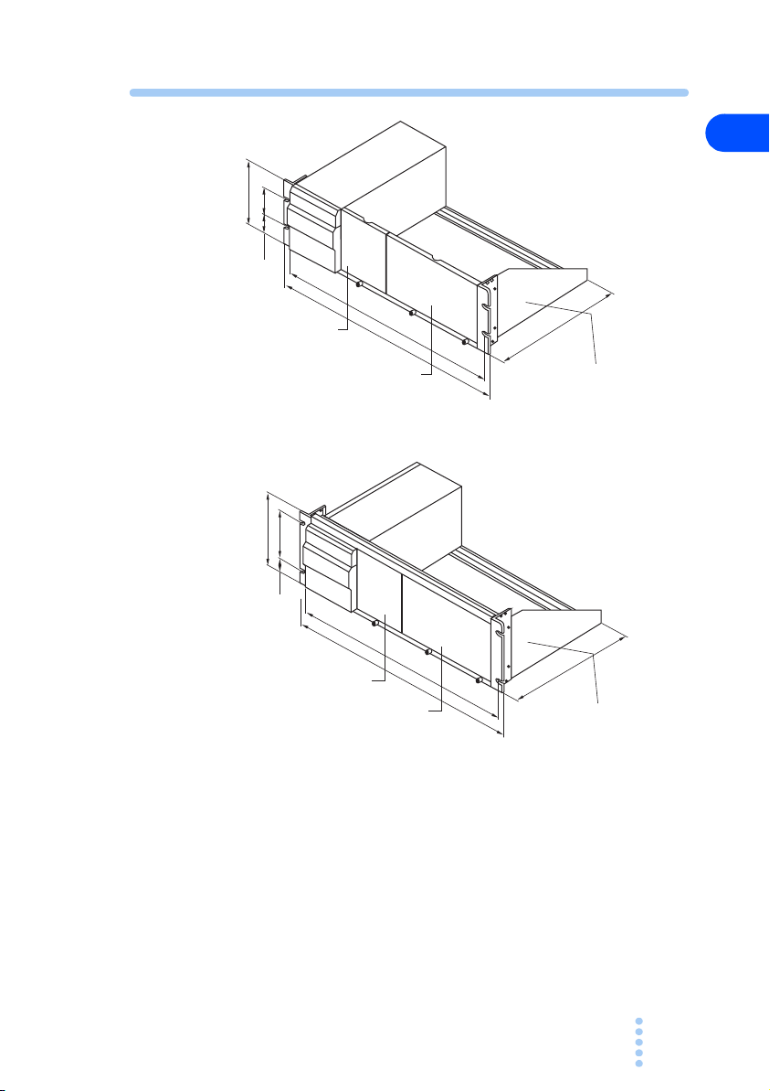
132.5 (5.22)
57 (2.24)
37.75
(1.49)
460 (18.11)
482 (18.98
)
260 (10.24)
Blank panel KBP3-4
Blank panel KBP3-2
149
100
460
480
260
24.5
Rack adapter KRA3
Inch rack EIA standard unit: mm (inch)
Milli rack JIS standard unit: mm
Blank panel KBP3-4
Blank panel KBP3-2
Rack adapter KRA150
1
General Description
Fig. 1-1 Example of installation for rack mount
options
PMC-A 21
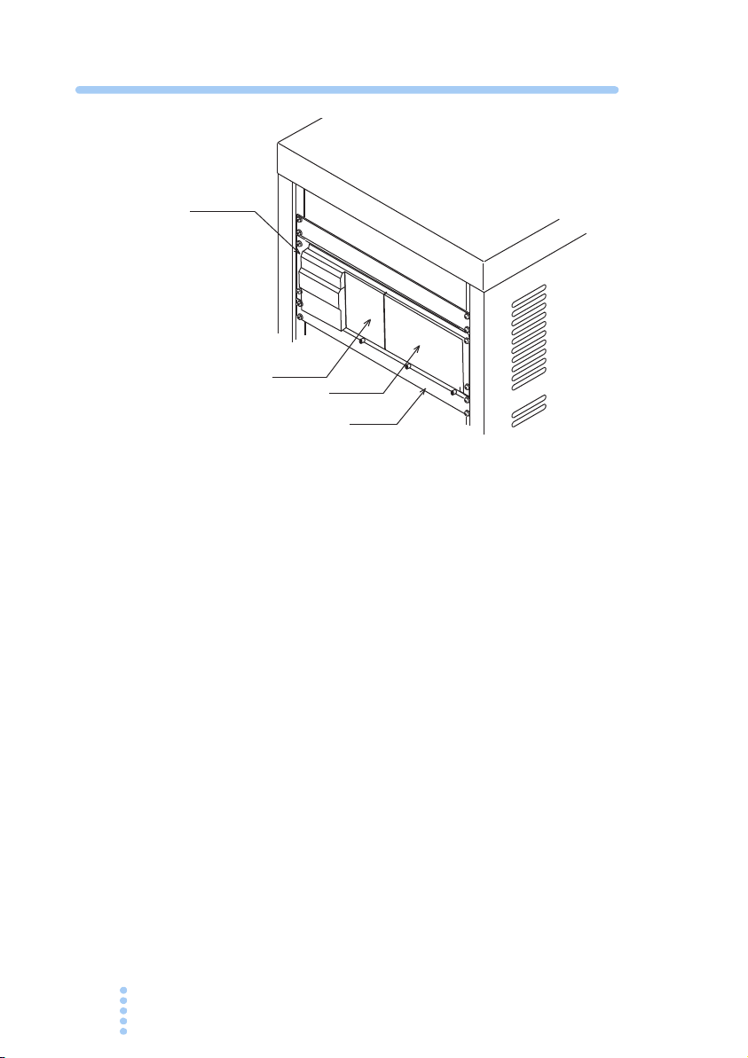
KRA150
KBP3-4
BP1H
KBP3-2
Fig. 1-2 Rack mounting example
22 PMC-A
Installation and Preparation
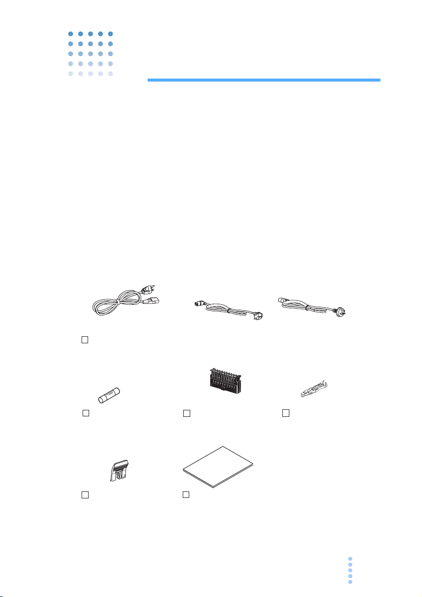
Operation Manual (1pc.)
[Z1-004-632]
Power cord (1pc.)
Fuse (1pc.)
Fuse rating varies
depending on the model.
For details, see Chapter
7, “Specifications.”
[84-49-0100]
Analog remote control
plug (1pc.)
*Attached to the J2 connector on
the rear panel.
[
84-49-0110]
[83-06-5060]
Analog remote
control contact ( 20 pcs.)
[85-AA-0004]
*
The power cord that is
provided varies depending
on the destination at the
factory shipment.
Lock Lever for J2 connector
(1pc.)
*Attached to the J2 connector on
the rear panel.
[85-AA-0005]
PLUG:CEE7/7
[85-10-0790]
PLUG:GB1002
PLUG:NEMA5-15
X 20
2
This chapter explains how to prepare the PMC-A for use from
unpacking to installation.
2.1 Checking the Package Contents
When you receive the PMC-A, check that all accessories are
included and that the accessories have not been damaged dur
ing transportation.
If any of the accessories are damaged or missing, contact your
Kikusui agent or distributor.
We recommend that all packing materials be saved, in case the
PMC-A needs to be transported at a later date.
-
PMC-A 23
Fig. 2-1 Accessories

2.2 Precautions Concerning Installation Location
Be sure to observe the following precautions when installing
the
PMC-A.
● Do not use the product in a flammable atmosphere.
To prevent the possibility of explosion or fire, do not use the
product near alcohol, thinner or other combustible materials,
or in an atmosphere containing such vapors.
● Avoid locations where the product is exposed to high
temperature or direct sunlight.
Do not place the product near a heater or in areas subject to
drastic temperature changes.
Operating temperature range: 0 °C to 40 °C (32 °F to 104 °F)
Storage temperature range: -10 °C to 60 °C (14 °F to 140 °F)
● Avoid humid environments.
Do not place the product in high-humidity locations-near a
boiler, humidifier, or water supply.
Operating humidity range: 10 %rh to 80 %rh
(no condensation)
Storage humidity range: less than 90 % rh
(no condensation)
Condensation may occur even within the operating relative
humidity range. In such cases, do not use the product until
the condensation dries up completely.
● Be sure to use it indoors.
The PMC-A is designed for safe indoor use.
● Do not place the product in a corrosive atmosphere.
Do not install the product in a corrosive atmosphere or in
environments containing sulfuric acid mist, etc. This may
cause corrosion of various conductors and bad contacts of
connectors leading to malfunction and failure, or in the
worst case, a fire.
24 PMC-A

However, operation in such environments may be possible
through alteration. If you wish to use the product in such
environments, consult your Kikusui agent or distributor.
● Do not place the product in a dusty location.
Accumulation of dust can lead to electric shock or fire.
● Do not use the product where ventilation is poor.
The power supply uses unforced air cooling. The air flows
form the bottom panel to the top panel. Do not block the bot
tom and top panels.
The top cover of the product may get high temperature, it
may cause burn on the skin.
Do not install the power supply with the side or front panel
facing up or down.
● Do not place objects on top of the product.
Placing heavy objects on the product may cause malfunction
of the power supply.
Do not stack the power supplies.
● Do not place the product on an inclined surface or loca-
tion subject to vibrations.
The product may fall or tip over causing damages and inju-
ries.
● Do not use the product in a location where strong mag-
netic or electric fields are nearby or a location where
large amount of distortion and noise is present on the
input power supply waveform.
The product may malfunction and cause electric shock or
fire.
-
2
Installation and Preparation
● Do not use the product near highly sensitive measuring
instruments or transceivers.
The noise generated by the product may affect them.
PMC-A 25

2.3 Precautions to Be Taken When Moving
See
the Product
When moving the product to the installation location or when
transporting the product, note the following points.
● Turn off the POWER switch.
Moving the product while the power is turned on can cause
electric shock or damage to it.
● Remove all wiring.
Moving the product with the cables connected can cause
wires to break or injuries due to the product falling over.
● When transporting the product, be sure to use the orig-
inal packing materials.
Otherwise, damage may result from vibrations or from the
product falling during transportation.
● Make sure this manual has been included.
2.4 Rack-mount Adaptor Installation
p.19
26 PMC-A
Before installing the rack-mount adaptor, remove the plastic
feet. How to remove plastic feet is illustrated in
Concerning installation, refer to the KRA3 or the KRA150
installation instructions.
Fig. 2-2.
 Loading...