


PART NO. IB021036
Oct. 2015
Installation and
Preparation
1
User’s Manual
PLZ-4WL Series Electronic Load
PLZ164WL
PLZ334WL
Basic Functions
Advanced Operations
Sequences
External Control
Maintenance
Specifications
2
3
4
5
6
7
App

This manual is intended for users of the product or persons
About PLZ-4WL Series Manual
teaching other users on how to operate the product.
The manual assumes that the reader has knowledge about
Power Supply.
• User’s manual (this manual)
User's manual is intended for first-time users of the PLZ4WL series. It gives an overview of the PLZ-4WL series and
describes various settings, measurement procedures,
maintenance, safety precautions, etc.
This manual is designed to be read from beginning to end.
You can review this manual when you are confused about
an operation or when a problem occurs.
• The communication interface manual
The communication interface manual describes the content
of the commands.
The interface manual is written for readers with sufficient
basic knowledge of how to control instruments using a
personal computer.
• Quick Reference
The quick reference briefly explains the panel description
and the basic operation of the PLZ-4WL.
• Setup Guide
The setup guide is intended for first-time users of the PLZ4WL series. It gives an overview of the PLZ-4WL series,
connecting procedures, safety precautions, etc. Please read
through and understand this guide before operating the
product.
Trademark acknowledgements
Microsoft and Windows are either registered trademarks or
trademarks of Microsoft Corporation in the United States and/
or other countries.
Other company names and product names used in this
manual are generally trademarks or registered trademarks of
the respective companies.
Copyrights
Reproduction and reprinting of operation manual, whole or
partially, without our permission is prohibited.
Both unit specifications and manual contents are subject to
change without notice.
© 2010 Kikusui Electronics Corporation
PDF and HTML files are included in the accompanying
CDROM. Adobe Reader 9.2 or later is required to view the
PDF files. Microsoft Internet Explorer 9 or later is required to
view the HTML files.
If you find any incorrectly arranged or missing pages in the
manual, they will be replaced. If the manual gets lost or soiled,
a new copy can be provided for a fee. In either case, please
contact Kikusui distributor/agent, and provide the “Kikusui Part
No.” given on the cover.
The Operation Manual has been prepared with the utmost
care; however, if you have any questions, or note any errors or
omissions, please contact Kikusui distributor/agent.
Product ROM versions that this manual
covers
This manual applies to products with firmware versions 1.0X.
When contacting us about the product, please provide us with:
The model (marked in the top section of the front panel)
The ROM version (see page 16)
The serial number (marked in the rear panel)
2 PLZ-4WL

• The PLZ164WL Electronic Load is also referred to as the
Notations used in this manual
WARNING
CAUTION
DESCRIPTION
See
Memo
Product Overview
PLZ164WL, the PLZ334WL Electronic Load is also referred
to as the PLZ334WL
• The word computer used in the text is a collective term for
personal computers and workstations.
• The following markings are used in this manual.
Indicates a potentially hazardous situation which, if
ignored, could result in death or serious injury.
The PLZ-4WL Series Electronic Load is a multifunctional
system designed to offer the highest levels of reliability and
safety. The electronic load contains a stable and highperformance current-control circuit that enables high-speed
load simulations. In addition, its CPU control feature works to
improve operability and multifunctional capability.
The high-precision current settings provide you with sufficient
resolution.
Because the electronic load comes standard with GPIB,
RS232C, and USB communication functions, it can be easily
incorporated into a wide range of test and inspection systems.
PLZ-4WL Series Models
Indicates a potentially hazardous situation which, if
ignored, may result in damage to the product or other
property.
Indicates information that you should know.
Explanation of terminology or operation principle.
Indicates reference to detailed information.
>
Indicates menu settings that you select. The menu item to
the left of the > symbol is a higher level menu.
SHIFT+key name
Indicates an operation that requires you to press a key
indicated in blue letters while holding down SHIFT.
Indicates useful information.
Model Maximum
Operating Current
PLZ164WL 50 A 0.3 V to 30 V 165 W
PLZ334WL 100 A 0.3 V to 30 V 330 W
Operating
Voltage
Power
Features
In addition to the high-performance constant-current,
constant-resistance, constant-voltage, and constant-power
modes, the PLZ-4WL Series Electronic Load offers a wide
variety of other features.
High-speed slew rate of 50 A/µs (PLZ334WL)
The rise and fall slew rate of the current when the PLZ-4WL
switches at 2 % to 100 % (20 % to 100 % in M range) of the
rated current in constant current mode is 50 A/µs
(PLZ334WL), which corresponds to fast rise and fall times
of 1.6 µs (for all types).
This allows you to conduct accurate transient-response
tests of DC power supplies and to accurately generate
simulated waveforms for use as dummy loads.
Variable slew rate
In constant current mode, the PLZ-4WL allows configuration
using slew rates (A/ µs).
This allows you to optimize the voltage drop caused by the
wire inductance that occurs when a load is switched or to
optimize the transient control of the equipment under test
(such as a constant-voltage power supply).
Higher precision
Higher precision is offered for current settings.
High resolution for minute current settings is provided using
a 3-range configuration. (0.02 mA resolution is possible in
the L range of the PLZ164WL.)
Operability
The PLZ-4WL employs a large LCD.
Measured values of voltage, current, and power at the load
input terminals are indicated at all times. The values are
indicated using larger characters than other sections to
improve visibility.
Coarse and fine adjustments using the rotary knob are
useful for setting values over a wide range.
The easy-to-use memory function enables repetitive tests.
Sequence function
User-defined sequence patterns can be saved to the
internal memory.
Up to 10 normal sequence programs and 1 fast sequence
program can be saved. Normal sequences can contain up
to 256 steps, and the fast sequence can contain up to 1024
steps.
You can edit sequences easily from the large LCD.
PLZ-4WL 3
Functions that are useful for battery discharge
What Is an Electronic Load?
PLZ-4WL Series
I
V
Constant-voltage
power supply
The current is constant even
when the voltage varies.
Current I
Voltage
V
0
V1
CC setting
0.1 V
3.3 V
30 V
0.1 A
Input current
Input voltage
Operating area where
specifications are
guaranteed
Actual operating
area
165 W
0.3 V
5.5 A
50 A
Logarithmic
scale
Operating area where
specifications are
guaranteed
0
50 mV
20 mV
0
Input current
Input voltage
0.3 V
50 A
Actual operating
area
Example for the PLZ164WL
testing
You can measure the time from when the load is turned on
until when it is turned off.
You can measure the time from the start of battery
discharge to the cutoff voltage (time measurement) by using
this function in conjunction with undervoltage protection
(UVP).
In voltage measurement, the voltage immediately before the
load turns off is measured. If you use the timer so that the
load turns off after a specified amount of time, you can
measure the closed-circuit voltage after a specified time has
elapsed since the start of battery discharge (voltage
measurement).
Standard-equipped GPIB, RS232C, and USB
interfaces
The PLZ-4WL comes standard-equipped with GPIB,
RS232C, and USB interfaces. It can be easily incorporated
into a wide range of test and inspection systems.
When the interfaces are used with the sequence function, a
variety of systems can be created.
To measure the characteristics of power sources and other
devices that produce energy, a load is required to consume
the energy. A variable resistor can be used as a simple load. A
device in which semiconductor devices such as transistors are
used instead of a variable resistor is referred to as an
“electronic load.” Using semiconductor components, an
“electronic load” can change the current and voltage freely, so
when it is used with a control circuit, it can function as a variety
of different types of loads.
Electronic loads can be used as loads for different types of
circuits, for switching power supplies and other types of DC
power supplies, for testing the characteristics and lifespans of
primary and secondary batteries, and for aging. You can use
the sequence function to create programs that simulate real
load conditions and use these programs to produce varying
loads in tests on devices such as power supplies for printers.
Operating Areas of the PLZ-4WL
As shown in the figure, the PLZ-4WL can be used within the
area enclosed by the constant voltage line defined by the
rated voltage, the constant power line defined by the rated
power, the constant current line defined by the rated current,
and the constant voltage line defined by the minimum
operating voltage (the enclosed area is where specifications
are guaranteed).
The specifications are not guaranteed for input voltages below
0.3 V (the values in the actual operating area). The minimum
operating voltage at which current begins to flow through the
PLZ-4WL is approximately 50 mV. If the input voltage is
gradually increased from 0 V, no current will flow until this
minimum operating voltage is exceeded. If the input voltage
exceeds the minimum operating voltage and a current greater
than or equal to 0.2 % of the range rating (greater than or
equal to 0.2 % of the H range when the PLZ-4WL is set using
the M range) starts flowing, the current can keep flowing even
when the voltage is reduced down to as low as approximately
20 mV.
There are AC electronic loads and DC electronic loads. The
PLZ-4WL is a DC electronic load for use with DC circuits.
Basic Operation Modes
The following six operation modes are available on the PLZ4WL.
1. Constant current mode (CC mode)
2. Constant resistance mode (CR mode)
3. Constant power mode (CP mode)
4. Constant voltage mode (CV mode)
5. Constant current and constant voltage mode (CC+CV
mode)
6. Constant resistance and constant voltage mode (CR+CV
mode)
Here, we will explain the simplest of the six modes: constant
current (CC) mode.
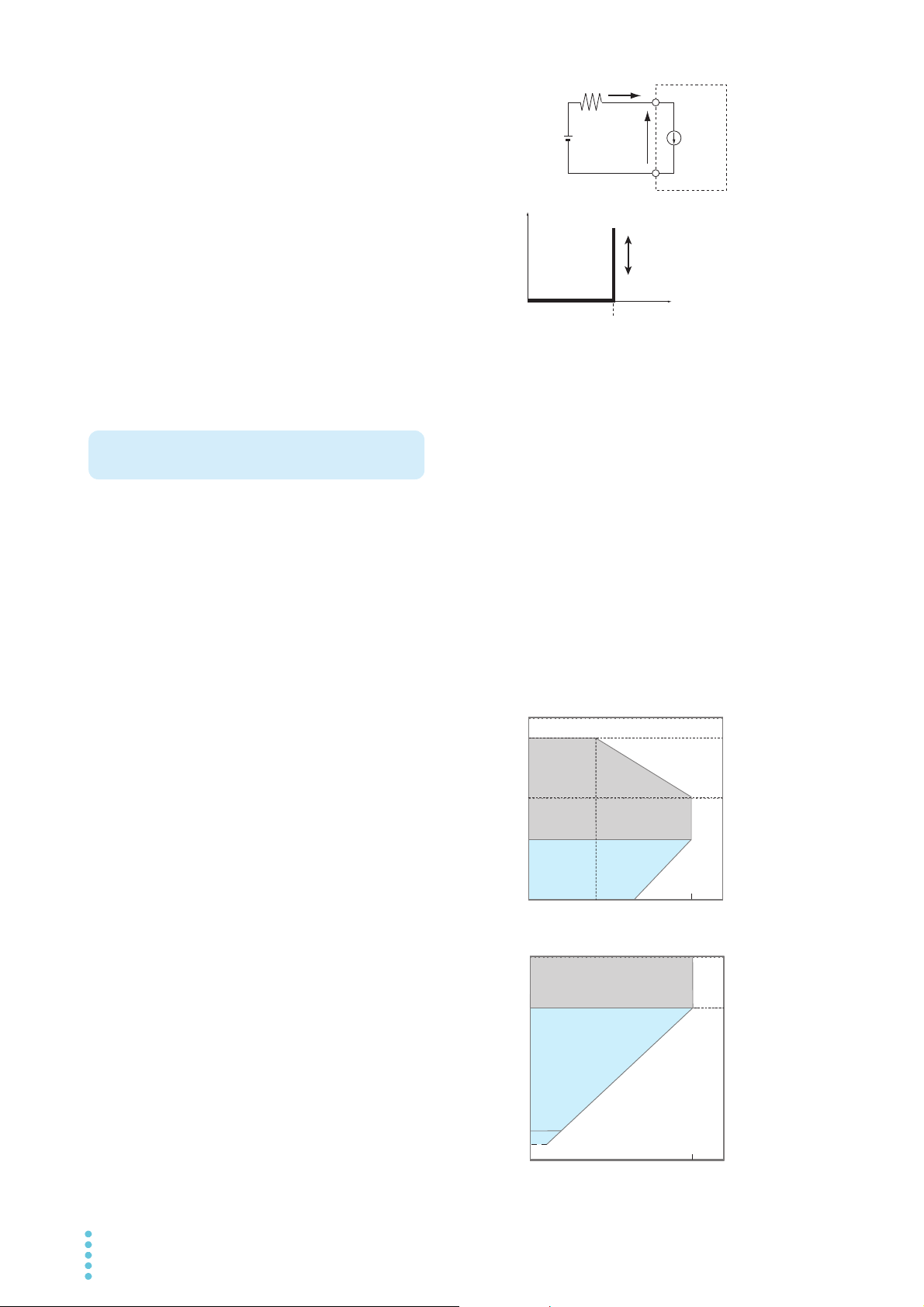
■ Constant Current Mode Operation
In constant current (CC) mode, the PLZ-4WL operates as a
constant-current load.
The PLZ-4WL sinks the specified current (I) regardless of the
output voltage (V1) of the constant-voltage power supply.
4 PLZ-4WL

Contents
About PLZ-4WL Series Manual 2
Notations used in this manual 3
Product Overview 3
What Is an Electronic Load? 4
Installation and
1
Preparation
Checking the Package Contents 12
Connecting the Power Cord 14
Turning the Power On 15
Load wiring 17
Methods for Ensuring Stable Operation 18
Connecting to the Load Input Terminals 21
Remote Sensing 24
Basic Functions
2
Panel Operation Basics 26
Turning the Load On and Off 27
Operation Modes 29
Constant Current Mode (CC mode) 30
Constant Resistance Mode (CR) 32
Constant Voltage Mode (CV mode) 34
Constant Power Mode (CP mode) 35
Switching 36
Slew Rate 38
Attachment to the rack adapter 13
Turning the POWER switch on 15
When the PLZ-4WL does not start
properly 16
Checking the version 16
Turning the POWER switch Off 16
Reducing the load wiring inductance 18
Optimizing the response speed 19
Do not apply excessive voltages to the
load input terminals 20
Match the polarities of the load input
terminals and the DUT terminals 20
Turning the load on 27
Turning the load off 28
Configuring CC mode 30
Configuring CC+CV mode 31
Configuring CR mode 32
Configuring CR+CV mode 33
Configuring CV mode 34
Configuring CP mode 35
Setting the switching level 36
Setting the switching interval 37
Turning the switching function on and off
37
Setting procedure 38
3
4
Soft Start 39
Short 40
Turning the short function on and off 40
Locking the Keys 41
Switching from Remote Mode to Local Mode
42
Advanced Operations
Memory Types 44
ABC Preset Memory 45
Saving settings to ABC preset memory 45
Recalling ABC preset memory entries 46
Setup Memory 47
Saving settings to setup memory 47
Recalling setup memory entries 48
Protection Functions 49
Protection function types 49
Clearing alarms 51
Response Speed 52
Elapsed Time Display and Auto Load-Off
Timer 53
Elapsed time display (Count Time) 53
Auto load-off timer (Cut Off Time) 53
Menu 54
Factory Default Settings (Initialization) 56
Sequences
Sequence Function 58
Normal sequences and fast sequences
58
Common Sequence Editing Operations 59
How Normal Sequences Work 60
Editing Steps in a Normal Sequence 62
Adding steps 62
Editing steps 62
Deleting steps 63
Sequence Example (Normal Sequence) 64
Editing program 1 65
Setting the steps of program 1 66
Editing program 2 68
Setting the steps of program 2 69
How Fast Sequences Work 70
Editing steps 72
Sequence Example (Fast Sequence) 74
Editing program 11 75
Setting the steps of program 11 76
Executing, Pausing, and Stopping Sequences
77
Executing sequences 77
Pausing a sequence 77
Stopping a sequence 78
When sequences cannot be executed 78
PLZ-4WL 5

5
External Control
External Control 80
About the J1 connector 81
J1 connector pin arrangement 82
Precautions for high-speed load
simulations 83
Superimposing Constant Current Mode (CC
Mode) 88
Turning the Load On and Off through External
Control 89
Signal Input for turning the load on and off
89
Load-on status signal output 90
Using a Trigger Signal to Control the PLZ-4WL
91
Controlling the Current Range Externally 92
Input for switching the range externally 92
Range status output 92
Alarm Signal 93
Alarm input 93
Alarm release input 93
Alarm status output 93
Monitor Signal Output 94
Trigger signal output 94
Current monitor output 94
Other functions 113
Common specifications 114
General specifications 115
Dimensions 116
Appendix
A Operating Area 118
Basic operation modes 118
How constant current (CC) mode works
119
How constant resistance (CR) mode
works 120
How constant power (CP) mode works
122
How constant voltage (CV) mode works
124
How constant current and constant
voltage (CC+CV) mode works 126
How constant resistance and constant
voltage (CR+CV) mode works 128
Operating areas of each model 130
B Sequence Program Creation
Table132
C Options 134
6
7
Maintenance
Inspection 96
Internal inspection 97
Backup battery replacement 97
Calibration 98
What gets calibrated? 98
Preparation 99
CC Mode Calibration (Calibration numbers 1,
2, and 3) 100
CV Mode Calibration (Calibration numbers 4
and 5) 102
Ending Calibration 104
Troubleshooting 105
Specifications
Ratings 108
Constant current (CC) mode 108
Constant resistance (CR) mode 109
Constant voltage (CV) mode 109
Constant (CP) power mode 110
Measurements 110
Switching mode 111
Slew rate 111
Soft start 11 2
Response 11 2
Remote sensing 112
Protection function 112
Sequence function 113
INDEX135
6 PLZ-4WL
Search by Topic
To solve problems
See "Troubleshooting" on page 105.
• What accessories are included in the package?
"Checking the Package Contents" p. 12
• The installation space is limited, so I want to
check the installation conditions.
See the included “Setup Guide”
document, or the electronic version of
the document on the CD-R.
---
• How do I connect the AC power supply?
"Connecting the Power Cord" p. 14
• What kind of load wiring should I use?
"Load wiring" p. 17
• How do I set the communication conditions
for remote control?
See the “Communication Interface
Manual” on the CD-R.
---
• How do I rack mount the PLZ-4WL? What
kind of parts are needed?
"Attachment to the rack adapter" p. 13
• I want to use the PLZ-4WL in CC mode.
"Constant Current Mode (CC mode)" p. 30
• I want to use the PLZ-4WL in CR mode.
"Constant Resistance Mode (CR)" p. 32
• I want to add CV mode to CC mode.
"Configuring CC+CV mode" p. 31
• How do I set the protection functions to
prevent damage to the DUT?
"Protection Functions" p. 49
• How do I use remote sensing to stabilize the
PLZ-4WL?
"Remote Sensing" p. 24
• How do I check the menu contents?
"Menu" p. 54
• How do I reset the PLZ-4WL to its factory
default settings?
"Factory Default Settings (Initialization)" p. 56
• How do I operate the PLZ-4WL at a
specified current? How do I save current
values to the preset memory?
"ABC Preset Memory" p. 45
• How do I edit sequence programs?
"Sequences" p. 57
• How do I control the PLZ-4WL using
external voltage?
"External Control" p. 80
• How do I stop a sequence that is being
executed?
"Executing, Pausing, and Stopping
Sequences"
p. 77
• How do I use an external contact to turn the
load on and off?
"Turning the Load On and Off through
External Control"
p. 89
• I want to know about the backup battery’s
replacement period.
"Backup battery replacement" p. 97
• How should I clean the PLZ-4WL?
"Cleaning the dust filter"
p. 96
• How do I calibrate the PLZ-4WL?
"Calibration"
p. 98
Preparation
Setup
Operation
Maintenance
PLZ-4WL 7
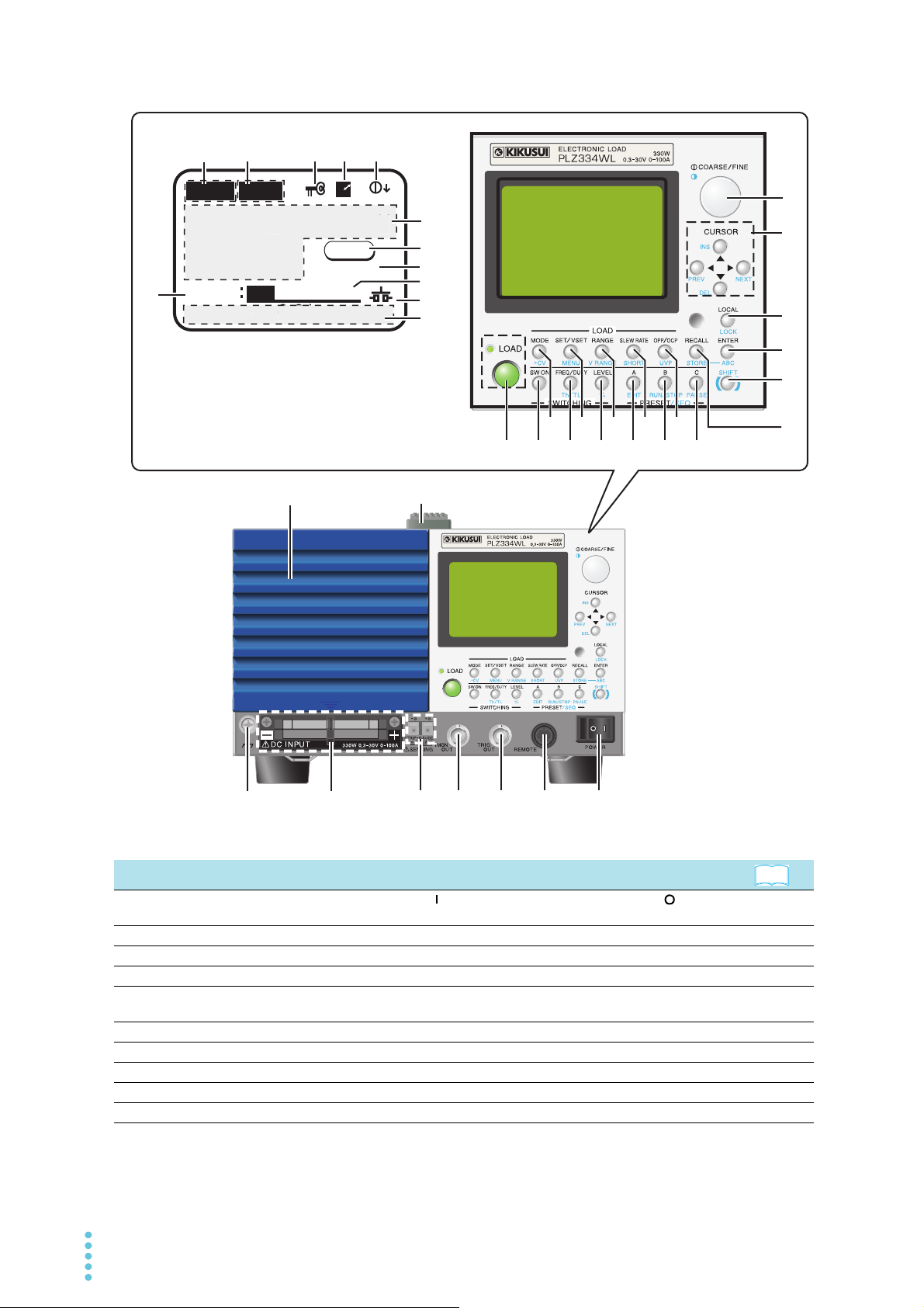
Front Panel
1
2
3
4
5
6
7
8
9
17 16
15
10
11
12
13
14
19
18
20
2122
26
2725
2423
0.00mA0.000
V
0.000
W
CC
SLEWRATE
0:06:23
0.000
A
0.01
mA/s
SET
H 100A 30V
R
C . C
0.00
0.00
0
V
0.000
W
S
E
0.01
/s
28
29
31
3230
33
34
35
36
37
39
38
Display
See
LEWRAT
mA
No. Name Function
POWER switch
1
REMOTE Connector for expanding functions. –
2
TRIG OUT Produces a pulse signal during sequence or switching operation. p. 94
3
I MON OUT An output terminal for monitoring the current. p. 94
4
Remote sensing
5
terminals
DC INPUT The load input terminals for connecting the DUT and the PLZ-4WL. p. 17
6
Chassis terminal A terminal connected to the chassis. p. 17
7
Air inlet An air inlet for cooling. It has a dust filter. –
8
Handle A handle for carrying the PLZ-4WL. –
9
Rotary knob Used to make selections and change settings. p. 26
10
Flip the switch to the ( ) side to turn the power on. Flip it to the ( ) side to
turn the power off.
Terminals for connecting remote sensing wires. p. 24
8 PLZ-4WL
p. 15

No. Name Function
11
CURSOR
INS key Inserts a step (sequence editing). –
DEL key Deletes a step (sequence editing). –
PREV key Returns to the previous screen (menu settings). –
NEXT key Switches to the next screen (menu settings). –
LOCAL key Used to switch to local mode from remote mode. p. 42
12
LOCK key Used to set the key lock. p. 41
ENTER key Used to confirm the input (menu settings). –
13
ABC key Used to save settings to the preset memory. p. 45
SHIFT key Shift key. p. 26
14
RECALL key Used to recall the setup memory. p. 48
15
STORE key Used to save the setup memory. p. 47
C key Used to access preset memory C. p. 45
16
PAUSE key Pauses the PLZ-4WL during sequence operation. p. 77
B key Used to access preset memory B. p. 45
17
RUN/STOP key Stops the PLZ-4WL during sequence operation. p. 77
A key Used to access preset memory A. p. 45
18
EDIT key Used to edit sequences. p. 57
LEVEL key Used to set the switching level to a current or conductance value. p. 36
19
% key Used to set the switching level to a percentage.
FREQ/DUTY key Used to set the switching frequency and duty ratio. p. 37
20
Th/TL key Used to set the switching time.
SW ON key Turns the switching function on and off. p. 37
21
LOAD key Turns the load on and off. p. 27
22
MODE key Switches the operation mode. p. 29
23
+CV key Adds CV mode (constant voltage) to CC or CR mode. p. 31 , p. 33
SET/VSET key Used to set the fundamental settings (current, conductance, voltage, or
24
MENU key Displays the menu setup screen. p. 54
RANGE key Switches between the appropriate ranges (current, conductance, voltage,
25
V RANGE key Switches between voltage ranges. –
SLEW RATE key Used to set the slew rate. p. 38
26
SHORT key Turns the short function on and off. p. 40
OPP/OCP key Used to set the power at which overpower protection (OPP) is activated or
27
UVP key Used to set the voltage at which undervoltage protection (UVP) is activated. p. 51
Current Range Displays the current range. –
28
Voltage range Displays the voltage range.
29
Lock icon Appears when the key lock is enabled. p. 41
30
Remote icon Appears during remote control. –
31
/FINE icon Indicates whether the rotary knob is set to coarse or fine adjustment. p. 26
ARSE
CO
32
mA/A Displays the measured current value. –
33
V Displays the measured voltage value. –
W Displays the measured power value. –
Operation status Indicates the operation mode being used or the status.
34
Elapsed time Displays the amount of time that has elapsed since the load was turned on. p. 53
35
Setting Displays the fundamental setting (current, voltage, power, or conductance). –
36
Short icon Appears when the short function is being used. p. 40
37
Multi display Displays settings other than the fundamental setting.
38
Set operation mode Displays the set operation mode. –
39
Up, down, left, and right keys. –
power).
or power) for the current operation mode.
the current at which overcurrent protection (OCP) is activated.
In CC+CV mode, CC or CV is displayed.
In CR+CV mode, CR or CV is displayed.
When a value can be set, it is underlined, and the item name is highlighted.
See
–
–
p. 50
p. 29
–
PLZ-4WL 9
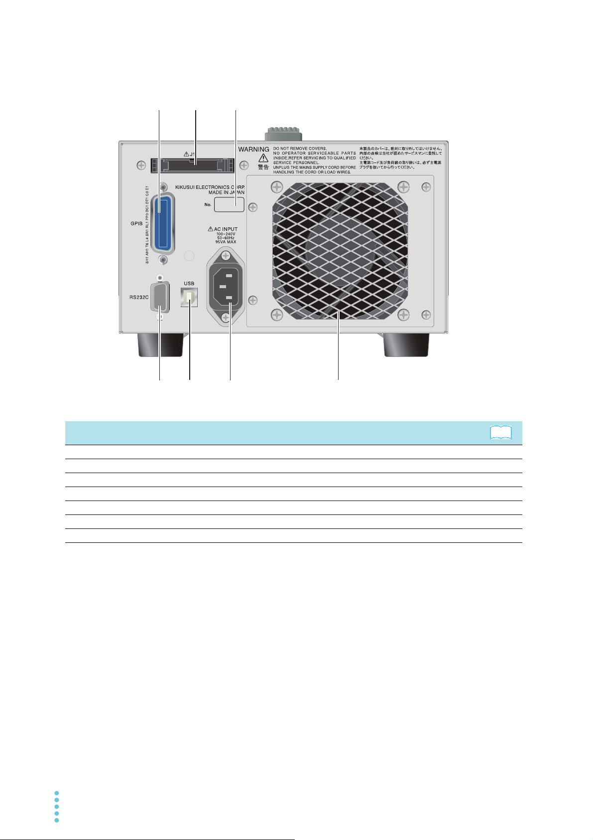
Rear Panel
1
3
2
4
6
5
7
No. Name Function
Air outlet Vent for cooling the PLZ-4WL. –
1
AC INPUT Power inlet. p. 14
2
USB USB port for controlling the PLZ-4WL remotely. –
3
RS232C RS232C port for controlling the PLZ-4WL remotely. –
4
GPIB GPIB cable connector for controlling the PLZ-4WL remotely. –
5
J1 connector External control connector p. 80
6
Serial number The serial number of the PLZ-4WL. –
7
See
10 PLZ-4WL

1
Installation and Preparation
This chapter describes how to unpack and
prepare this product before you use it.
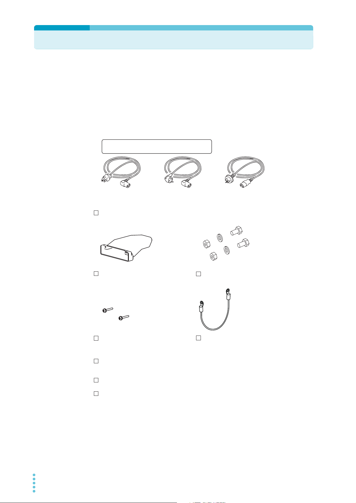
Checking the Package Contents
Load input terminal cover (1 pc.)
Load input terminal screw set (2 pc.)
Power code (1 pc.)
[M1-100-012]
[M5-101-007]
[M4-100-007]
Load input terminal
cover screws (2 pc.)
[M3-112-018]
[Q1-500-122]
Chassis connection wire (1 pc.)
[91-80-6940]
Setup Guide (1 pc.)
Quick Reference
(Japanese 1sheet, English 1sheet)
CD-ROM (1 pc.)
Plug: NEMA5-15
Rating: 125Vac/10 A
[85-AA-0003]
Plug: CEE7/7
Rating: 250Vac/10 A
[85-AA-0005]
Plug: GB1002
Rating: 250Vac/10 A
[85-10-0790]
oror
The power cord that is provided varies depending on the
destination for the product at the factory-shipment.
When you receive the product, check that all accessories are included and that the
accessories have not been damaged during transportation.
If any of the accessories are damaged or missing, contact your Kikusui agent or distributor.
We recommend that you keep all packing materials, in case the product needs to be
transported at a later date.
Accessories
12 PLZ-4WL
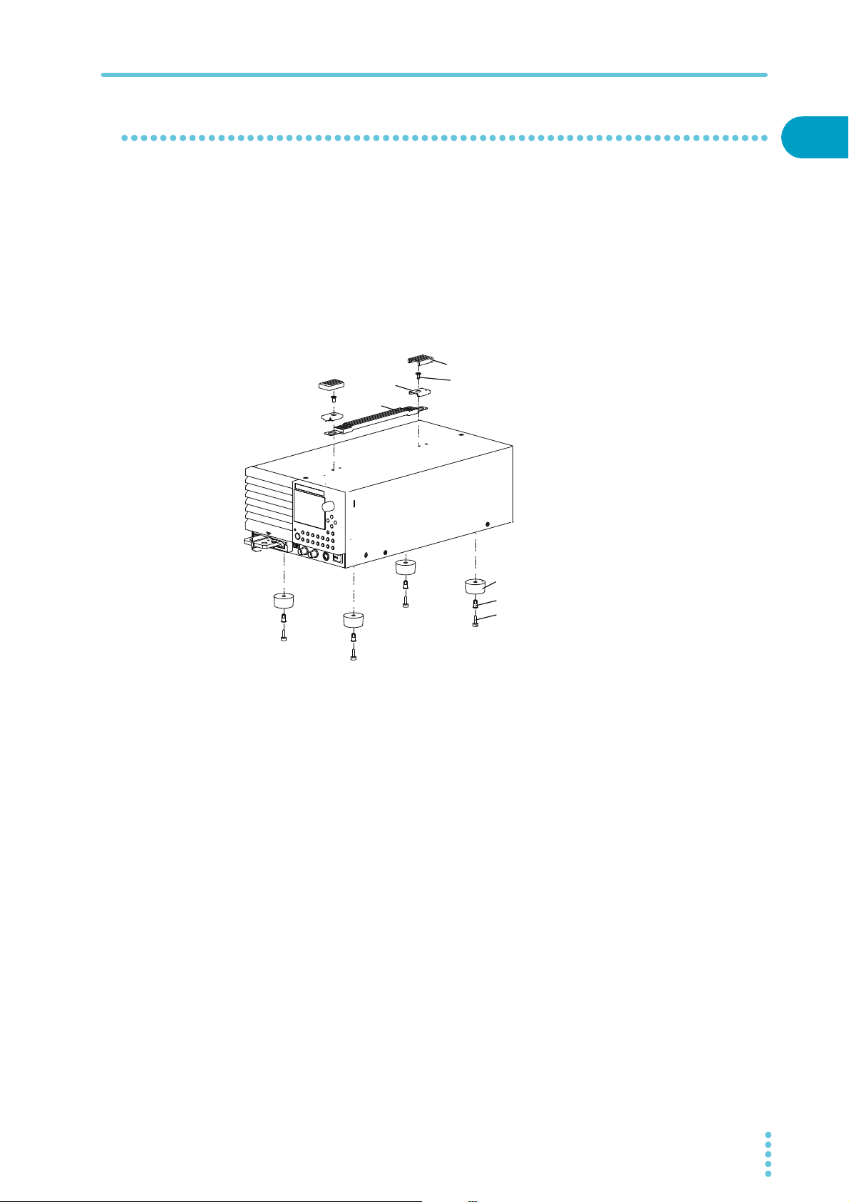
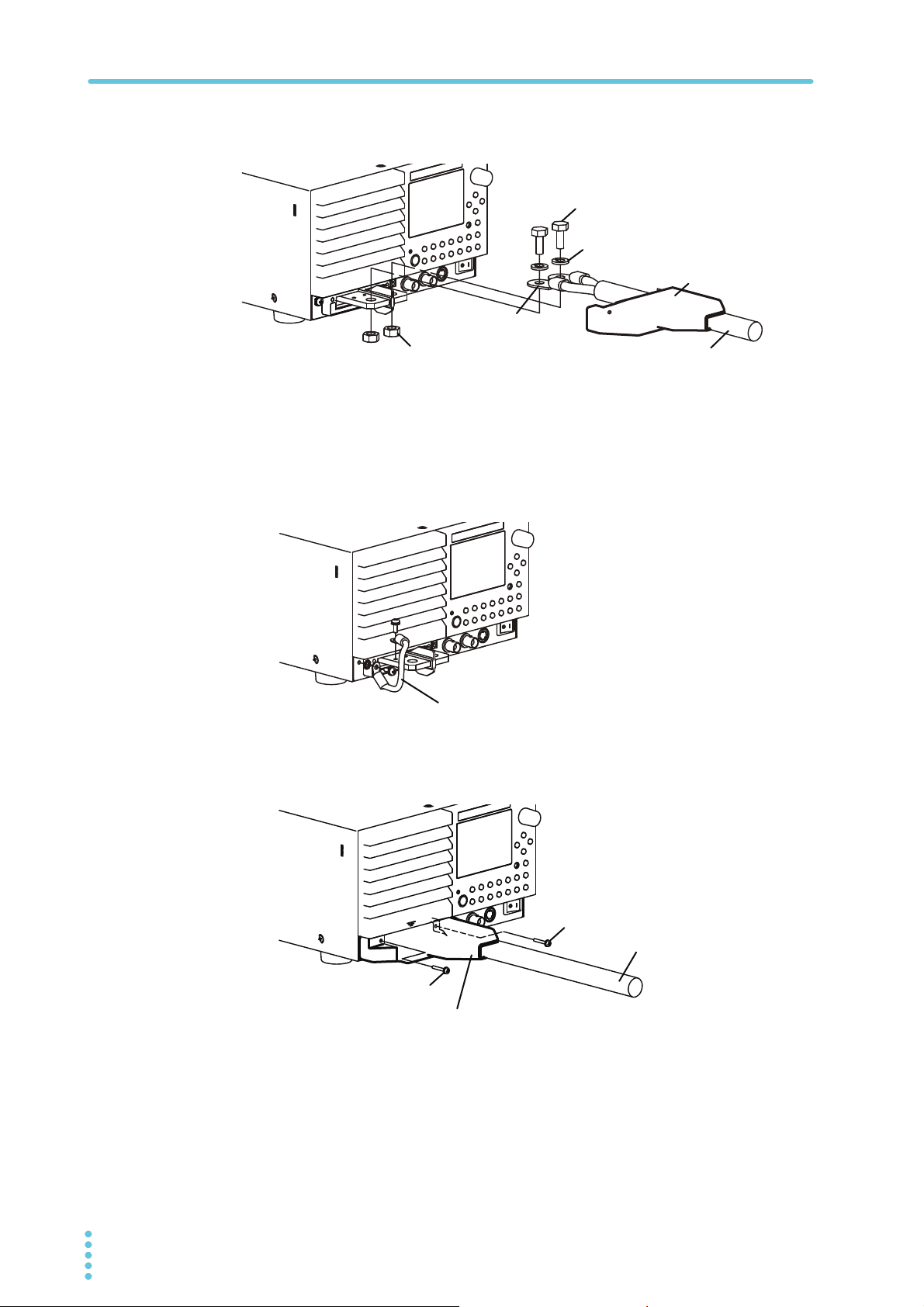
Attachment to the rack adapter
Cover
Handle
Bracket
M4 flat-head screw
(M4 × 0.7 × 8)
Rivet
Foot
Screw pin
Before assemble the unit to the rack adapter, remove the handle and the feet. As for the
instruction of mount assembly, please refer to the instruction manual of KRA series.
Install the suitable support angles applying to the used rack system to support the instrument.
In case the unit is disassembled from the rack adapter it is recommended that all the
removed parts are kept in the storage.
Once the unit is disassembled from the rack adapter please attach all the removed parts to
original location of each part.
Removing the handle and feet
Checking the Package Contents
1
Installation and Preparation
Pull up on the handle cover (two locations).
1
Unfasten the M4 flat-head screws (two locations) and remove the entire
2
handle.
While pulling down on the feet (there are four of them), use a
3
screwdriver to loosen their screw pins, and then remove them.
PLZ-4WL 13
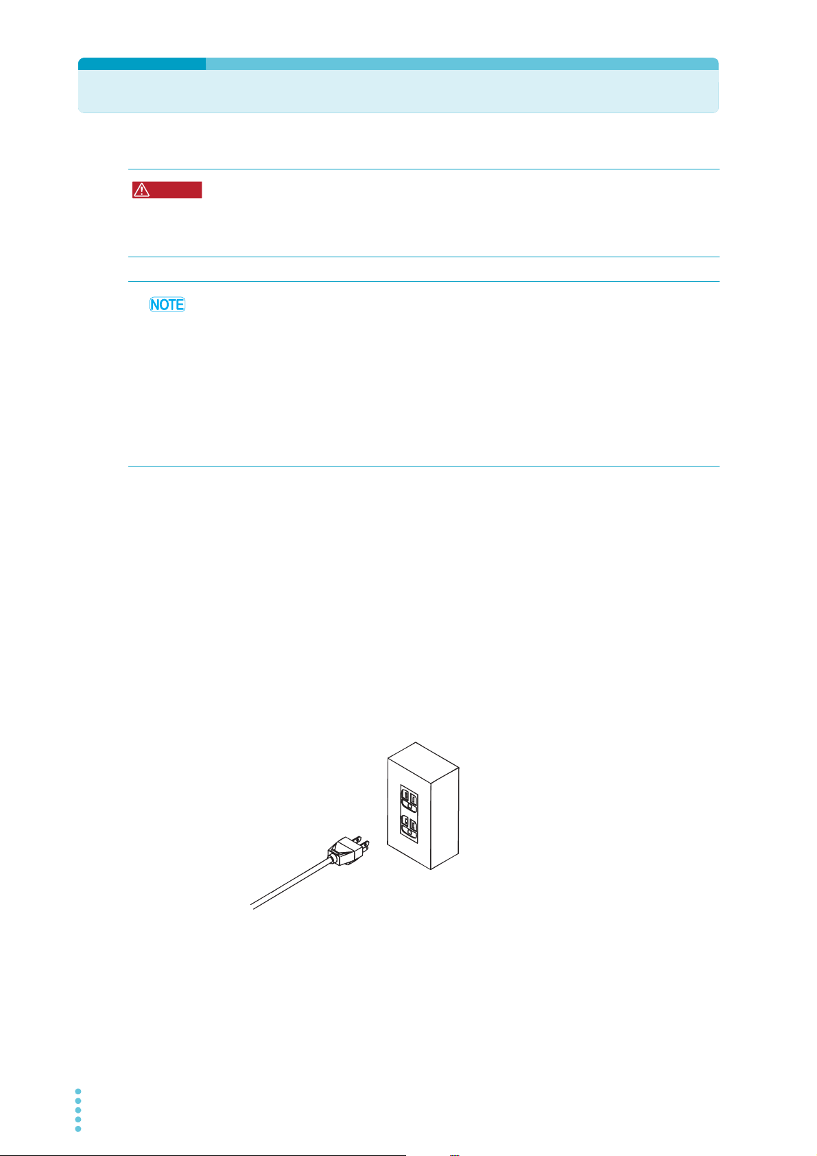
Connecting the Power Cord
WARNING
To a properly grounded outlet
To avoid electric shock, observe the following precautions.
• This product is IEC Safety Class I equipment (equipment with a protective conductor
terminal). Be sure to earth ground the product to prevent electric shock.
• Connect the protective conductor terminal to earth ground.
• Use the supplied power cord to connect to an AC power line.
If the supplied power cord cannot be used because the rated voltage or the plug shape is
incompatible, have a qualified engineer replace it with an appropriate power cord that is 3
m or less in length. If obtaining an appropriate power cord is difficult, consult your Kikusui
agent or distributor.
• A power cord with a plug can be used to disconnect the product from the AC line in an
emergency. Connect the plug to an easily accessible power outlet so that the plug can be
removed from the outlet at any time. Be sure to provide adequate clearance around the
power outlet.
• Do not use the supplied power cord for other devices.
This product falls under IEC Overvoltage Category II (energy-consuming equipment supplied
from the fixed installation).
Check that the POWER switch is off.
1
Check whether or not the AC power line is compatible with the input
2
rating of the product.
The voltage that can be applied is any of the nominal power supply voltages in the
range of 100 Vac to 240 Vac. The frequency is 50 Hz or 60 Hz.
Frequency range: 47 Hz to 63 Hz
Connect the power cord to the rear-panel AC INPUT.
3
Connect the power cord plug to an outlet with a ground terminal.
4
14 PLZ-4WL
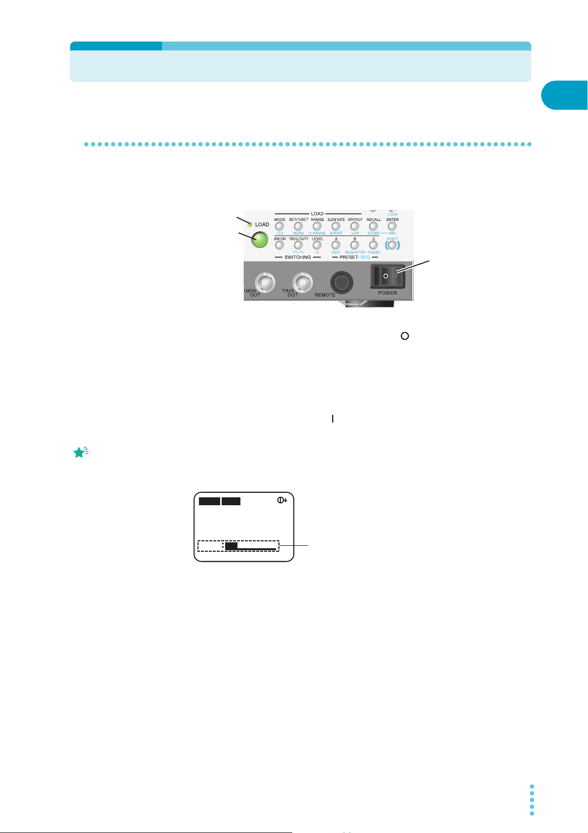
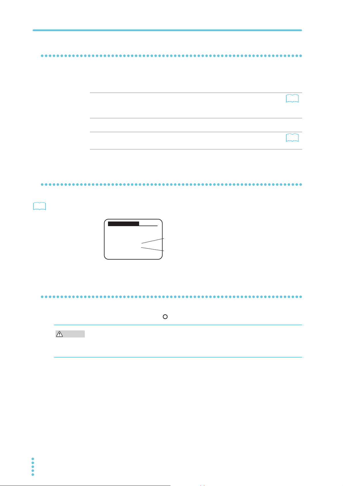
Turning the Power On
Memo
Constant current (CC) mode is selected
in this screen, so you can enter the current,
which is the fundamental setting.
0.00mA0.000
V
0.000
W
CC
SLEWRATE
0.500
A
0.01
mA/μs
SET
H 50A 30V
Turning the POWER switch on
If the POWER switch is turned on for the first time after purchasing the PLZ-4WL, the PLZ4WL starts up using factory default settings. For all other cases, the PLZ-4WL starts up using
the settings that existed when the POWER switch was turned off the last time.
Load-on indicator LED
LOAD key
Check that the POWER switch is turned off ( ).
1
1
Installation and Preparation
POWER switch
The condition in which
characters “SET” is
highlighted is called the
fundamental setting entry
condition.
Check that the power cord is correctly connected.
2
Check that nothing is connected to the DC INPUT (load input terminal)
3
on the front panel.
Turn the POWER switch on ( ).
4
Check that the display is in the fundamental setting entry condition.
5
The measured value displayed (section with mA, V, and W unit) indicates coarse zero.
The characters “SET” shown under the measured value is highlighted with an
underline. You can enter the fundamental setting for the selected operation mode.
Push LOAD.
6
Check that the LED above the key illuminates.
Push LOAD again.
7
Check that the LED above the key turns off.
PLZ-4WL 15
If an odd sound, odd odor, fire, or smoke occurs around or in the PLZ-4WL, remove the
power plug from the outlet or turn off the power switch.
Turning the Power On
See
See
See
Example for the PLZ164WL.
CAUTION
When the PLZ-4WL does not start properly
This section introduces what measures you can take when the PLZ-4WL does not start
properly. If following the remedy shown here does not solve the problem, contact your Kikusui
agent or distributor.
Nothing is displayed. Make sure that the power cord is connected
Abnormal current or voltage values are
being displayed.
An alarm has occurred. A protection function has been activated. Eliminate
Checking the version
p. 54
You can check the firmware and ROM versions by selecting “1. Model Info” on the menu
screen.
Model Information
[ PLZ164WL ]
VERSION
SUB 1.00
MAIN 1.02
PREV
properly, and then turn the POWER switch on
again.
Adjusts the contrast of the display.
Turn the PLZ-4WL POWER switch off and then on
again.
all the cause of the alarm.
Firmware version
ROM version
p. 26
--
p. 49
Turning the POWER switch Off
Flip the POWER switch to the ( ) side to turn the PLZ-4WL off.
After you turn the POWER switch off, wait at least 5 seconds after the fan stops before you
turn the POWER switch back on. Turning the PLZ-4WL on too soon after you turn it off can
cause damage to the inrush current limiter circuit, as well as reduce the life of components
such as the POWER switch and the internal input fuses.
The PLZ-4WL saves the panel settings (except the load on/off setting) that were in use
immediately before the POWER switch was turned off. When you turn on the POWER switch,
the PLZ-4WL starts up with the saved settings. If the POWER switch is turned off immediately
after the settings have been changed, the last settings may not be stored.
16 PLZ-4WL

Load wiring
WARNING
CAUTION
• Improper use of load wires may lead to fire. Use load wires whose capacity is
adequate for the PLZ-4WL’s rated output current.
• Possible electric shock. Use load wires whose rated voltage meets or exceeds the
PLZ-4WL’s isolation voltage. For details on the PLZ-4WL’s isolation voltage, see
Chap.7 "General specifications".
• Use a load wire with sufficient diameter for the current as well as non-flammable or flameresistant cover.
1
If the wiring that you use for the load has a high resistance, the voltage will drop significantly
when current flows, and the voltage at the load input terminals may fall below the minimum
operating voltage. Using the following table as a reference, select wiring whose nominal
cross-sectional area is as thick as possible.
A wire’s temperature is determined by the resistive loss based on the current, the ambient
temperature, and the wire’s external thermal resistance. The following table shows the
current capacity of heat-resistant vinyl wires that have a maximum allowable temperature of
60 C when one of the wires is separated and stretched out horizontally in air in an ambient
temperature of 30 C. The current must be reduced under certain conditions, such as when
vinyl wires that have a low heat resistance are used, when the ambient temperature is 30 C
or greater, or when wires are bundled together and little heat is radiated.
Nominal CrossSectional Area
2
]
[mm
2 14 (2.08) 27 10
3.5 12 (3.31) 37 –
5.5 10 (5.26) 49 20
8 8 (8.37) 61 30
14 6 (13.3) 88 50
22 4 (21.15) 115 80
30 2 (33.62) 139 –
38 1 (42.41) 162 100
50 1/0 (53.49) 190 –
60 2/0 (67.43) 217 –
80 3/0 (85.01) 257 200
100 4/0 (107.2) 298 –
125 –– 344 –
150 –– 395 300
200 –– 469 –
250 –– 556 –
325 –– 650 –
AWG (Reference Cross-
Sectional Area) [mm
2
]
Allowable Current
[A] (Ta = 30C)
1
KikusuiRecommended
Current [A]
Installation and Preparation
1
Excerpts from Japanese laws related to electrical equipment.
PLZ-4WL 17

Methods for Ensuring Stable Operation
When you use the PLZ-4WL at a high response speed, it is important to reduce the
inductance of the load wiring and configure the response speed setting appropriately. If the
conditions are not configured appropriately, oscillation and other forms of operational
instability may occur.
Reducing the load wiring inductance
Voltage generated by current changes
The wiring has an inductance of L. If current I changes quickly, a large voltage is induced on
both sides of the wiring. All of this voltage will be applied to the load input terminals of the
electronic load if the impedance of the DUT is low. Voltage E (hereafter referred to as the
generated voltage), which is generated according to the wiring inductance L and the amount
of current change I is expressed as follows:
E
L
EUT
Load input terminal
Generally, a wire’s inductance is approximately 1 µH per meter of wire. If the DUT and the
electronic load are connected using 1 m of wire (total length of the positive and negative
wiring), a change in current of 50 A/µs will generate a voltage of 50 V.
The negative load input terminal provides the reference potential for the external control
signal. The generated voltage may cause the device connected to the external control signal
to malfunction.
When the electronic load is in constant-voltage, constant-resistance, or constant-power
mode, it uses the voltage at the load input terminals to change the load current. So it is easy
for the electronic load to be influenced by the generated voltage.
+
-
PLZ-4WL
I
ΔI/ΔT
E = L × (ΔI/ΔT)
E: Generated voltage
L: Load wiring inductance
ΔI: Change in current
ΔT: Duration of time over which
the current changes
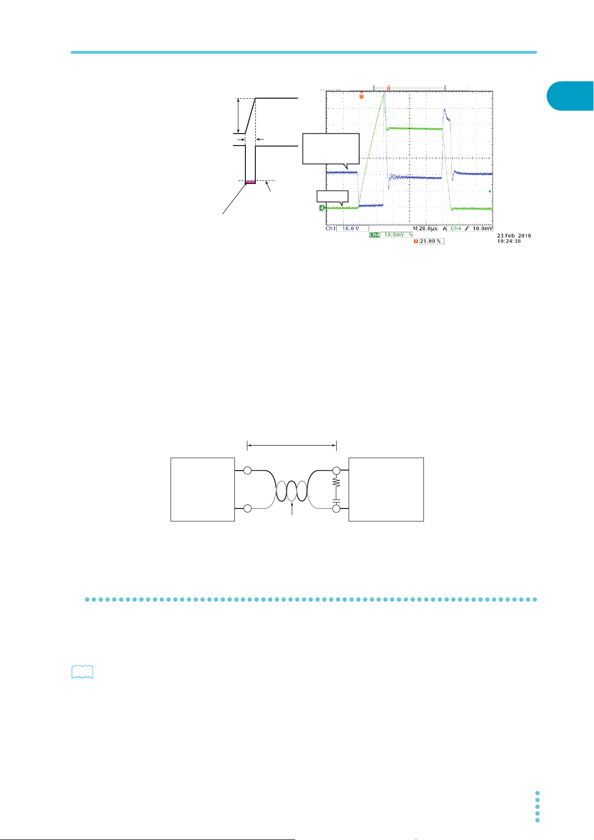
Large voltage drop caused by current changes during switching
operation
Make the wiring to the DUT as short as possible, and twist it. When the wiring is long or
contains a large loop, its inductance increases, and current changes caused by switching
operations will result in large voltage drops.
If the instantaneous voltage value at the load input terminals drops below the minimum
operating voltage, the recovery response will be delayed significantly. You need to be
especially careful when the slew rate setting is high and when switching operation is
performed at high currents.
18 PLZ-4WL
Current
See
Methods for Ensuring Stable Operation
Example of waveform
1
ΔI
ΔT
Voltage across the
load input terminals
Minimum operating
voltage
This change results in unstable
oscillation and hunting.
To make sure that the voltage resulting from inductance remains within the range of the
electronic load’s minimum operating voltage and maximum input voltage, make the wiring as
short as possible and twist the wiring, or reduce the slew rate. If it is not necessary to operate
at a high response speed, reduce the slew rate in CC mode, or reduce the response speed in
CR mode.
Voltage across
the load input
terminals
Current
Current phase lag
Even during DC operation, it is possible for the phase lag of the current to result in unstable
electronic-load control and oscillation. Make the wiring as short as possible, and twist it.
If you only need to use DC operation, connecting a capacitor and a resistor to the load input
terminals can reduce oscillation. Do not exceed the capacitor’s ripple-current rating.
Installation and Preparation
Keep the wire short
100 cm or less
+
Device
under test
–
Twist
Optimizing the response speed
You can change the response speed in CV mode and CR mode. The wiring inductance can
cause the current to lag the voltage. This can result in unstable control of the PLZ-4WL and
oscillation.
p. 52
To ensure stable operation, reduce the response speed.
+
R
PLZ-4WL Series
Electronic Load
C
–
Example: R = 10 Ω, C = 100 µF
PLZ-4WL 19
Methods for Ensuring Stable Operation
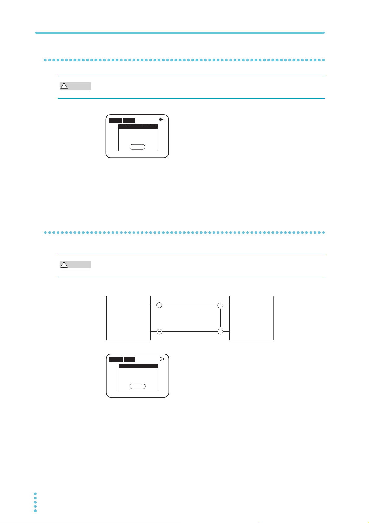
CAUTION
CAUTION
Do not apply excessive voltages to the load input terminals
Do not apply a voltage that is greater than the maximum voltage of 30 Vdc to the load input
terminals. Doing so may damage the product.
H 50A 30V
100.00A150.00
16.50
CC
SLEWRATE
The maximum voltage that can be applied to the load input terminals is 30 Vdc. You cannot
use voltages that exceed 30 Vdc. When excessive voltage is applied, the protection functions
are activated. Lower the voltage of the DUT immediately.
ALARM
OVP
W
ENTER
0.000
SET
2.50 mA/μs
V
A
Match the polarities of the load input terminals and the DUT terminals
Connecting the electronic load to the DUT with the polarities reversed can result in the flow
of excessive current and damage to the DUT and the electronic load.
Connect each load input terminal to the terminal on the DUT with the same polarity.
++
Device
under test
H 50A 30V
H 500mA
ALARM
0.00mA0.000
Reverse
0.000
W
ENTER
0.000
SET
CC
SLEWRATE
The protection functions are activated when a reverse voltage of approximately 0.4 V or
greater is applied. If this happens, turn off the DUT immediately.
25.0 μA/μs
V
A
≤30 Vdc
PLZ-4WL Series
Electronic Load
20 PLZ-4WL
Connecting to the Load Input Terminals
WARNING
CAUTION
Positive terminal
Negative terminal
Load input terminals
Load input terminal cover
Cut to match the thickness
of the load wiring.
This section explains how to connect the DUT to the DC INPUT terminals on the front panel.
Possible electric shock.
• Do not touch the load input terminals when the output is turned on.
• Always use the load input terminal cover.
• To avoid damaging the product, observe the following precautions. Do not connect the DUT
to the DC INPUT terminals when the load is on.
• To avoid overheating, observe the following precautions. Attach crimping terminals to the
wires, and use the attached screw set to connect them.
1
Installation and Preparation
Using the load input terminal cover
Pass the wiring that you intend to connect to the load through the load input terminal cover.
Cut the cover’s sleeves to match the thickness of the wiring
Connection procedure
Turn the POWER switch off.
1
Make sure that the output of the DUT is off.
2
Attach crimping terminals to the load wiring.
3
The DC INPUT terminals have open bolt holes (M8) for connecting the load wiring.
Attach appropriate crimping terminals.
PLZ-4WL 21
Pass the wiring that you want to connect to the load through the
4
attached load input terminal cover.
Connecting to the Load Input Terminals
Nut (M8)
Load input terminal cover
Crimping terminal
Spring washer (M8)
Bolt (M8 × 18)
Load wiring
Chassis connection wire
Screw (M3 × 18)
Screw (M3 × 18)
Connect the load input terminal cover to the panel
so that the terminals are not exposed.
Load wiring
Connect the load wiring to the load input terminals using the load input
5
terminal screw set that came with the PLZ-4WL.
Using the PLZ-4WL’s screws, connect one end of the chassis-
6
connection wire that came with the PLZ-4WL to the chassis, and connect
the other end to the negative load input terminal.
If the DUT (a power supply or similar device) is grounded, connect the chassis
connection wire to the positive or negative terminal in the same manner as the DUT.
You can also float the chassis connection wire, not connecting it to the positive or
negative terminal.
Push the load input terminal cover into the front panel, and then fix it
7
into place using the load input terminal cover screws that came with the
PLZ-4WL (maximum tightening torque: 1 N-m).
Connect the load wires to the output terminals of the DUT.
8
Connect the positive load input terminal to the positive terminal of the DUT, and
connect the negative load input terminal to the negative terminal of the DUT.
22 PLZ-4WL
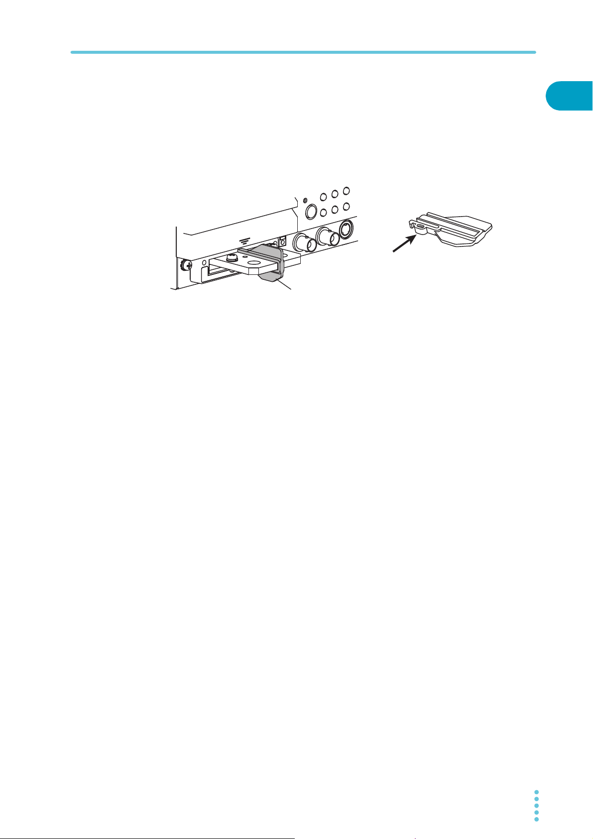
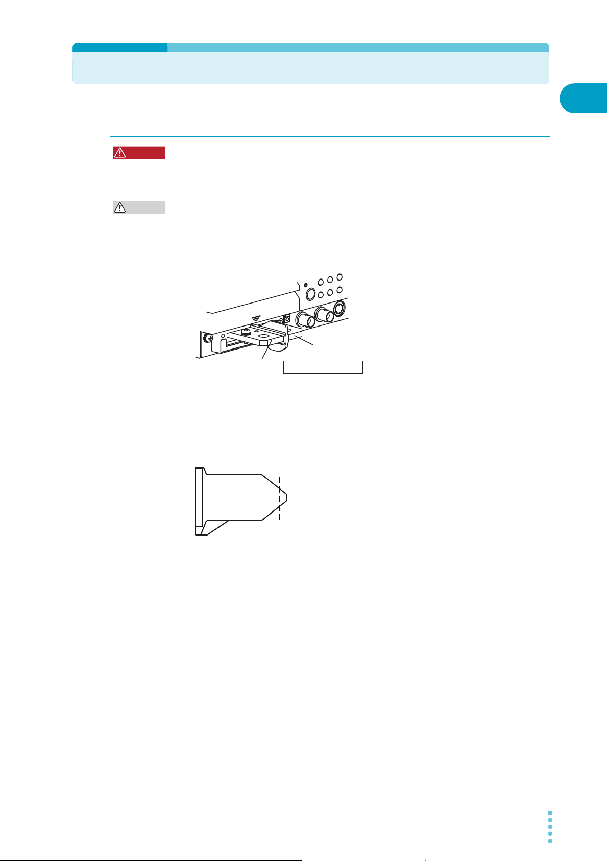
Removing the terminal barrier
Connecting to the Load Input Terminals
A barrier is placed between the DC INPUT terminals when the PLZ-4WL is shipped from the
factory. To avoid shorting between the terminals, we recommend that you leave the barrier in
when you make connections.
When testing some types of devices, you may want to remove the barrier.
■ Removing the terminal barrier
Push the tab on the bottom side of the barrier, and pull the barrier towards you.
Terminal barrier
Push this part, and pull the barrier toward you.
Terminal barrier
1
Installation and Preparation
PLZ-4WL 23
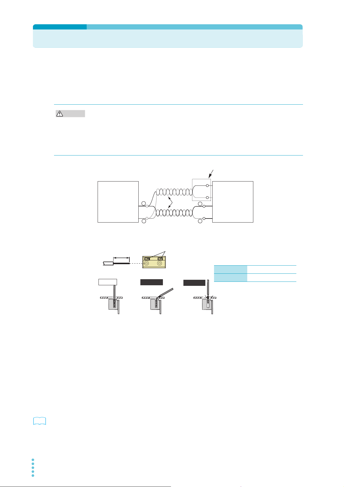
Remote Sensing
CAUTION
DUT
PLZ-4WL Series
Electronic Load
+S
-S
Remote sensing terminals
+
+
–
–
Red
White
Twist
Correct
Incorrect
Incorrect
The stripped wire is
touching the chassis.
The wire strands are
touching the chassis.
10 mm
STRIP-GAUGE
While pressing here with a
screwdriver, insert the wire.
Single wire: AWG26 to AWG18
Twisted wire: AWG22 to AWG20
See
When the load wiring is long, the voltage drop caused by the wiring’s resistance cannot be
ignored. “Remote sensing” is a function that can be used to compensate for this voltage drop.
To accurately set the resistance, voltage, and power, use remote sensing.
Remote sensing makes operation more stable by improving the transient characteristics in
the constant-resistance (CR), constant-voltage (CV), and constant-power (CP) modes.
• Never wire the sensing terminals while the POWER switch is turned on. Doing so may
damage the internal circuitry.
• If a wire is disconnected during remote sensing, the PLZ-4WL and the DUT may be
damaged. Make sure that wire connections are secure.
• Do not reverse the wiring of the OUT and COM terminals of the SENSING terminal. Doing
so may damage the internal workings of the PLZ-4WL.
The table below indicates sizes of the wires that you can use to connect to the sensing
terminals. Strip approximately 10 mm of coating from the end of the wiring.
Turn the POWER switch off.
1
Connect the sensing terminals to the DUT using sensing wires.
2
Connect the positive remote sensing terminal on the rear panel (+S) to the positive
terminal (+) on the DUT. In the same way, connect the negative remote sensing
terminal (-S) on the rear panel to the negative terminal (-) on the DUT. Connect the
wiring as close to the DUT as possible.
Enabling remote sensing
p. 54
24 PLZ-4WL
To turn remote sensing on or off, from the menu, select “2. Configuration” > “4. Remote
Sensing” > “Sensing.”

2
Basic Functions
This chapter explains the operations for
each operation mode and other basic
functions.

Panel Operation Basics
0.000
V
Fine adjustment
Small arrow
0.000
V
Coarse adjustment
Large arrow
0.00mA 0.000
V
0.000
W
CC
SLEWRATE
0.000
A
0.01
mA/μs
SET
H 50 A 30 V
CP
CC
CR
CV
Popup menu
You can perform operations from the operation panel on the front of the PLZ-4WL. The PLZ4WL produces a beeping sound to notify you when you make an invalid selection or perform
an invalid key operation.
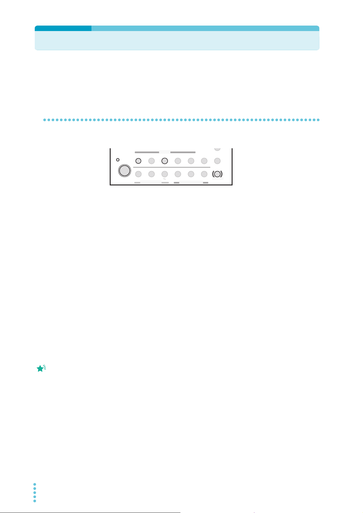
Function of the LOAD key
If you press LOAD when the load is turned off, the LOAD LED lights, and the load turns on. If
you press LOAD when the load is turned on, the LOAD LED turns off, and the load turns off.
How to use the rotary knob
Use the rotary knob to set values such as the current and resistance. Turning the rotary knob
clockwise increases a value and turning it counterclockwise decreases the value.
■ Coarse and fine adjustment
You can switch between coarse and fine adjustment by pressing the rotary knob. When the
down arrow shown at the upper right corner of the screen is large, coarse adjustment is
selected; when it is small, fine adjustment is selected.
The fine adjustment setting resolution is ten times that of coarse adjustment. During coarse
adjustment, you can make even more coarse adjustments by holding LOCAL while you turn
the rotary knob.
When you set a value, it is convenient to first use coarse adjustment to set the value roughly
and then to switch to fine adjustment to set it precisely.
Popup menu operation
Some keys show a popup menu when you press them. If you press the key again while the
menu is shown, the selected item changes. The selected item changes to the next lowest
item each time you press the key. When you finish the key operation, the item at that point is
selected, and the popup menu is cleared automatically.
How to use the SHIFT key
The SHIFT key switches the function of each key. If you press a key without holding down
SHIFT, the function indicated above the key is enabled; if you press a key while holding down
SHIFT, the function indicated below the key is enabled.
For example, if you press SET/VSET without holding down SHIFT, the SET/VSET (indicated
in black) function is enabled. If you press SET/VSET while holding down SHIFT, the MENU
(indicated in blue) is enabled.
This manual denotes the operation of pressing a key while holding down SHIFT as
SHIFT+(notation above the key). For example, the selection of the MENU key is denoted as
“MENU (SHIFT+SET/VSET).” In this case, press SET/VSET while holding down SHIFT.
Adjusting the display contrast
You can adjust the contrast of the display by turning the rotary knob while you hold SHIFT.
26 PLZ-4WL

Turning the Load On and Off
CAUTION
See
See
See
See
The load is on when current is flowing through the PLZ-4WL or when the PLZ-4WL is
supplying current. The load is off when current is not flowing through the PLZ-4WL and the
PLZ-4WL is not supplying current. You can turn the PLZ-4WL’s load on and off by pressing
LOAD. The terms “load on” and “load off” appear frequently in this manual, so please
remember them.
To avoid damaging the PLZ-4WL, be sure to follow the proper procedures for turning the
load on and off.
Turning the load on
Make sure that the load is off.
1
Apply the output of the DUT to the PLZ-4WL.
2
If you are using a relay, electromagnetic switch, or other device in the connection
between the load input terminals and the output terminals of the DUT, turn the device
on.
2
Basic Functions
p. 54
p. 54
p. 89
p. 39
Press LOAD to turn on the load.
3
■ Starting with the load turned on
By factory default, the load is not turned on unless you press LOAD after turning on the
POWER switch.
To start the PLZ-4WL with the load turned on, from the menu, select “2. Configuration” > “2.
Power On” > “Load On” > “ON.” Turn the power switch off and then on again to enable the
settings.
■ Displaying the time that has elapsed since the load was turned on
This function, which displays the time that has elapsed since the load was turned on, is useful
when used in conjunction with undervoltage protection (UVP) in discharge tests of batteries
and capacitors. By factory default, the time is not displayed.
To display the time from load on to load off, from the menu, select “1. Setup” > “1. Function” >
“Count Time” > “ON.” Turn the power switch off and then on again to enable the settings.
■ Using an external control signal to turn the load on and off
You can turn the load on and off using external control signals from a relay or other device.
■ Gradually raising the PLZ-4WL’s input current
In constant current mode (CC mode), you can set the PLZ-4WL to raise its input current
gradually (soft start).
PLZ-4WL 27

Turning the Load On and Off
See
Turning the load off
Press LOAD to turn off the load.
1
Turn off the output of the DUT. If you are using a relay, electromagnetic
2
switch, or other device in the connection between the load input
terminals and the output terminals of the DUT, turn the device off.
■ Turning the load off after a specified amount of time
The function for turning the load off after a specified period of time is convenient for discharge
testing of batteries and capacitors. By factory default, the load on timer is off.
p. 54
To turn the load on timer on, from the menu, select “1. Setup” > “4. Cut Off” > “Time,” and set
the time. Turn the power switch off and then on again to enable the settings.
When the load turns off, a popup window appears indicating the input voltage at the time the
load was turned off.
28 PLZ-4WL

Operation Modes
CC
CC+CV CR+CV
CR CV CP
0.00mA0.000V
0.000W
CC
SLEWRATE
0.000
A
0.01
mA/μs
SET
H 50 A 30 V
CP
CC
CR
CV
Operation mode
+
CV
MODE
+
CV
MODE
+
CV
MODE
+
CV
MODE
+
CV
MODE
+
CV
MODE
+
CV
MODE
SHIFT
+
+
CV
MODE
SHIFT
+
The following four operation modes are available on the PLZ-4WL. Constant voltage mode
can be added to constant current mode or constant resistance mode (+CV).
• Constant current mode (CC mode, CC+CV mode)
• Constant resistance mode (CR mode, CR+CV mode)
• Constant voltage mode (CV mode)
• Constant power mode (CP mode)
2
Switching between operation modes
To switch between operation modes, press MODE while the load is off.
You can press +CV (SHIFT+MODE) in CC mode or CR mode to add CV mode. You can add
CV mode even while the load is on.
Basic Functions
PLZ-4WL 29
Constant Current Mode (CC mode)
Memo
In constant current mode (CC mode), you set the current [A]. You can also add constant
voltage mode (+CV mode) to constant current mode (CC mode).
Configuring CC mode
Select the operation mode, and set the current.
STORE
PAUSE
LOCK
ENTER
ABC
SHIFT
LOAD
SET / VSET
MENU
FREQ / DUTY
Th/TL
SWITCHING
RANGE
VRANGE
LEVEL
SHORT
EDIT
ABC
PRESET
MODE
LOAD
+
CV
SW ON
Make sure that the load is off.
1
The load is off when the LED to the upper left of the LOAD key is off. If the LED is lit,
SLEW RATE
OPP / OCP
UVP
RUN / STOP
I
RECALL
SEQ
press LOAD to turn the load off.
When “SET” is
highlighted, the PLZ-4WL
is in the fundamental
setting entry condition.
Press MODE to select the operation mode (CC).
2
The operation mode popup menu appears.
Press MODE repetitively until CC is highlighted on the menu. After you select the
operation mode, the popup menu disappears, and “CC” appears on the display.
Press RANGE to select the current range.
3
The current range popup menu appears.
Each time you press RANGE, the range switches between L, M, and H. Press RANGE
until the range that you want to select is highlighted. After you select a range, the
popup menu disappears, and the range that you selected appears along with its full
scale value. The full scale value varies depending on the model.
Press VRANGE (SHIFT+RANGE) to select the voltage range.
4
The voltage range popup menu appears.
Each time you press VRANGE (SHIFT+RANGE), the voltage range switches between
4 V and 30 V. Press VRANGE (SHIFT+RANGE) until the range that you want to select
is highlighted. After you select a voltage range, it appears on the display.
Check that the display is in the fundamental setting entry condition.
5
If SET is not highlighted, press SET/VSET to switch to the fundamental setting entry
condition.
Turn the rotary knob to set the current.
6
The CC mode settings are complete. When you press LOAD, the LOAD LED lights, and the
PLZ-4WL starts supplying current. You can change the current even when the load is on.
30 PLZ-4WL

Configuring CC+CV mode
SWITCHING
ENTER
SHORT
EDIT
SLEW RATE
RUN / STOP
UVP
PAUSE
STORE
RECALL
ABC
LOAD
Th/TL
FREQ / DUTY
MENU
PRESET
SEQ
I
LEVEL
VRANGE
RANGE
SW ON
+
CV
MODE
LOAD
SET / VSET
LOCK
SHIFT
ABC
OPP / OCP
Memo
CC+CV mode is constant current mode (CC mode) with CV mode added to it. You can add
CV mode even while the load is on.
Configure the constant current settings.
1
To configure the settings, refer to "Configuring CC mode".
Press +CV (SHIFT+MODE) to add CV mode.
2
The PLZ-4WL switches to CC+CV mode, and “CC+CV” appears on the display.
Make sure that the PLZ-4WL is in the fundamental setting entry
3
condition.
When “SET” is
highlighted, the PLZ-4WL
is in the fundamental
setting entry condition.
If SET is not highlighted, press SET/VSET to switch to the fundamental setting entry
condition.
Turn the rotary knob to set the current and voltage.
4
The value that you can set (current or voltage) changes when you press SET/VSET.
Constant Current Mode (CC mode)
2
Basic Functions
The CC+CV mode settings are complete. Press LOAD to start testing. You can change the
current and voltage even when the load is on.
PLZ-4WL 31

Constant Resistance Mode (CR)
SWITCHING
ENTER
SHORT
EDIT
SLEW RATE
RUN / STOP
UVP
PAUSE
STORE
RECALL
ABC
LOAD
Th/TL
FREQ / DUTY
MENU
PRESET
SEQ
I
LEVEL
VRANGE
RANGE
SW ON
+
CV
MODE
LOAD
SET / VSET
LOCK
SHIFT
ABC
OPP / OCP
Memo
In constant resistance mode (CR mode), you set the inverse of the resistance, the
conductance [S]. You can also display the resistance value converted from the conductance
value.
Conductance [S] = 1/resistance []
You can also add constant voltage mode (+CV mode) to constant resistance mode (CR
mode).
Configuring CR mode
Select the operation mode, and set the conductance.
When “SET” is
highlighted, the PLZ-4WL
is in the fundamental
setting entry condition.
Make sure that the load is off.
1
The load is off when the LED to the upper left of the LOAD key is off. If the LED is lit,
press LOAD to turn the load off.
Press MODE to select the operation mode (CR).
2
The operation mode popup menu appears.
Press MODE repetitively until CR is highlighted on the menu. After you select the
operation mode, the popup menu disappears, and “CR” appears on the display.
Press RANGE to select the current range.
3
The current range popup menu appears.
Each time you press RANGE, the range switches between L, M, and H. Press RANGE
until the range that you want to select is highlighted. After you select a range, the
popup menu disappears, and the range that you selected appears along with its full
scale value. The full scale value varies depending on the model.
Press VRANGE (SHIFT+RANGE) to select the voltage range.
4
The voltage range popup menu appears.
Each time you press VRANGE (SHIFT+RANGE), the voltage range switches between
4 V and 30 V. Press VRANGE (SHIFT+RANGE) until the range that you want to select
is highlighted. After you select a voltage range, it appears on the display.
Check that the display is in the fundamental setting entry condition.
5
If SET is not highlighted, press SET/VSET to switch to the fundamental setting entry
condition.
The resistance value converted from the conductance value appears in the multi
display. If a different value appears in the multi display, press SET/VSET to display the
resistance.
32 PLZ-4WL

Turn the rotary knob to set the conductance.
SWITCHING
ENTER
SHORT
EDIT
SLEW RATE
RUN / STOP
UVP
PAUSE
STORE
RECALL
ABC
LOAD
Th/TL
FREQ / DUTY
MENU
PRESET
SEQ
I
LEVEL
VRANGE
RANGE
SW ON
+
CV
MODE
LOAD
SET / VSET
LOCK
SHIFT
ABC
OPP / OCP
Memo
6
The CR mode settings are complete. When you press LOAD, the LOAD LED lights, and the
PLZ-4WL starts supplying current. You can change the conductance even when the load is
on.
Configuring CR+CV mode
Constant Resistance Mode (CR)
2
When “SET” is
highlighted, the PLZ-4WL
is in the fundamental
setting entry condition.
CR+CV mode is constant resistance mode (CR mode) with CV mode added to it. You can
add CV mode even while the load is on.
Configure the constant resistance settings.
1
To configure the settings, refer to "Configuring CR mode".
Press +CV (SHIFT+MODE) to add CV mode.
2
The PLZ-4WL switches to CR+CV mode, and “CR+CV” appears on the display.
Make sure that the PLZ-4WL is in the fundamental setting entry
3
condition.
If SET is not highlighted, press SET/VSET to switch to the fundamental setting entry
condition.
Turn the rotary knob to set the conductance and the voltage.
4
The value that you can set (conductance or voltage) changes when you press SET/
VSET.
Basic Functions
The CR+CV mode settings are complete. Press LOAD to start testing. You can change the
conductance and voltage even when the load is on.
PLZ-4WL 33

Constant Voltage Mode (CV mode)
SWITCHING
ENTER
SHORT
EDIT
SLEW RATE
RUN / STOP
UVP
PAUSE
STORE
RECALL
ABC
LOAD
Th/TL
FREQ / DUTY
MENU
PRESET
SEQ
I
LEVEL
VRANGE
RANGE
SW ON
+
CV
MODE
LOAD
SET / VSET
LOCK
SHIFT
ABC
OPP / OCP
Memo
In constant voltage mode (CV mode), you set the voltage [V].
Configuring CV mode
Select the operation mode, and set the voltage.
Make sure that the load is off.
1
The load is off when the LED to the upper left of the LOAD key is off. If the LED is lit,
press LOAD to turn the load off.
When “SET” is
highlighted, the PLZ-4WL
is in the fundamental
setting entry condition.
Press MODE to select the operation mode (CV).
2
The operation mode popup menu appears.
Press MODE repetitively until CV is highlighted on the menu. After you select the
operation mode, the popup menu disappears, and “CV” appears on the display.
Press RANGE to select the current range.
3
The current range popup menu appears.
Each time you press RANGE, the range switches between L, M, and H. Press RANGE
until the range that you want to select is highlighted. After you select a range, the
popup menu disappears, and the range that you selected appears along with its full
scale value. The full scale value varies depending on the model.
Press VRANGE (SHIFT+RANGE) to select the voltage range.
4
The voltage range popup menu appears.
Each time you press VRANGE (SHIFT+RANGE), the voltage range switches between
4 V and 30 V. After you select a voltage range, it appears on the display. Press
VRANGE (SHIFT+RANGE) until the range that you want to select is highlighted.
Check that the display is in the fundamental setting entry condition.
5
If SET is not highlighted, press SET/VSET to switch to the fundamental setting entry
condition.
Turn the rotary knob to set the voltage.
6
The CV mode settings are complete. When you press LOAD, the LOAD LED lights, and the
PLZ-4WL starts supplying current. You can change the voltage even when the load is on.
34 PLZ-4WL

Constant Power Mode (CP mode)
SWITCHING
ENTER
SHORT
EDIT
SLEW RATE
RUN / STOP
UVP
PAUSE
STORE
RECALL
ABC
LOAD
Th/TL
FREQ / DUTY
MENU
PRESET
SEQ
I
LEVEL
VRANGE
RANGE
SW ON
+
CV
MODE
LOAD
SET / VSET
LOCK
SHIFT
ABC
OPP / OCP
Memo
In constant power mode (CP mode), you set the power [W].
Configuring CP mode
Select the operation mode, and set the power.
Make sure that the load is off.
1
The load is off when the LED to the upper left of the LOAD key is off. If the LED is lit,
press LOAD to turn the load off.
2
Basic Functions
When “SET” is
highlighted, the PLZ-4WL
is in the fundamental
setting entry condition.
Press MODE to select the operation mode (CP).
2
The operation mode popup menu appears.
Press MODE repetitively until CP is highlighted on the menu. After you select the
operation mode, the popup menu disappears, and “CP” appears on the display.
Press RANGE to select the current range.
3
The current range popup menu appears.
Each time you press RANGE, the range switches between L, M, and H. Press RANGE
until the range that you want to select is highlighted. After you select a range, the
popup menu disappears, and the range that you selected appears along with its full
scale value. The full scale value varies depending on the model.
Press VRANGE (SHIFT+RANGE) to select the voltage range.
4
The voltage range popup menu appears.
Each time you press VRANGE (SHIFT+RANGE), the voltage range switches between
4 V and 30 V. Press VRANGE (SHIFT+RANGE) until the range that you want to select
is highlighted. After you select a voltage range, it appears on the display.
Check that the display is in the fundamental setting entry condition.
5
If SET is not highlighted, press SET/VSET to switch to the fundamental setting entry
condition.
Turn the rotary knob to set the power.
6
The CP mode settings are complete. When you press LOAD, the LOAD LED lights, and the
PLZ-4WL starts supplying current. You can change the voltage even when the load is on.
PLZ-4WL 35

Switching
Th TL
FREQ
0[A
]
(
0 %
)
LEVEL[A
][S]
[%]
SET[A
]
(
100 %
)
Edge at which the pulse is output from the TRIG OUT connector
LEVEL: Switching level
FREQ: Frequency of the switching
interval
Th: HIGH time of the switching
interval.
TL: LOW time of the switching
interval.
SWITCHING
ENTER
SHORT
EDIT
SLEW RATE
RUN / STOP
UVP
PAUSE
STORE
RECALL
ABC
LOAD
Th/TL
FREQ / DUTY
MENU
PRESET
SEQ
I
LEVEL
VRANGE
RANGE
SW ON
+
CV
MODE
LOAD
SET / VSET
LOCK
SHIFT
ABC
OPP / OCP
The switching function is used to switch between two preset load currents. Switching can be
performed in CC mode and CR mode.
Switching is suitable for transient-response testing of regulated DC power supplies and
similar devices.
To use the switching function, you need to set a switching level and a switching interval and
then turn on the switching function. You can configure switching while the load is on or off.
When you execute switching, a trigger signal is produced from the TRIG OUT terminal on the
front panel.
Example in CC Mode
Setting the switching level
You can set the switching level to a current or conductance value or to a percentage.
■ Setting the switching level to a current or conductance value
Press LEVEL.
1
The LEVEL key lights, and in CC mode, the current can be set; in CR mode, the
conductance can be set.
Turn the rotary knob to set the switching level.
2
■ Setting the switching level to a percentage
The specified current or conductance level is equivalent to 100 %.
Press % (SHIFT+LEVEL).
1
The LEVEL key lights, and you can set the switching level to a percentage.
36 PLZ-4WL
Turn the rotary knob to set the switching level (0.0 % to 100.0 %).
2

Setting the switching interval
Memo
You can set the switching interval by specifying a frequency and duty ratio or by specifying an
amount of time.
■ Setting the switching interval by specifying a frequency and duty ratio
Set the frequency and the duty ratio (the ratio of HIGH to LOW). It does not matter whether
you set the frequency or the duty ratio first. In the following example, the frequency will be set
first.
Switching
2
Press FREQ/DUTY until “FREQ” is highlighted.
1
The FREQ/DUTY key lights, and the frequency can be set. Pressing FREQ/DUTY
switches between “FREQ” and “DUTY.”
Turn the rotary knob to set the frequency (1 Hz to 50 kHz).
2
The frequency setting resolution varies depending on the specified frequency. The
PLZ-4WL switches between units (Hz and kHz) automatically.
Press FREQ/DUTY to highlight “DUTY.”
3
The FREQ/DUTY key lights, and the duty ratio can be set.
Turn the rotary knob to set the duty ratio (5 % to 95 %).
4
The minimum time interval is 10 μs. The maximum duty ratio is limited as the
frequency gets higher.
■ Setting the switching interval using two (HIGH and LOW) operation times
(Th and TL)
Set the HIGH and LOW times. It does not matter whether you set the HIGH or LOW time first.
In the following example, the HIGH time will be set first.
Press Th/TL (SHIFT+FREQ/DUTY) until “Th” is highlighted.
1
The Th/TL key lights, and the HIGH time can be set. Pressing Th/TL (SHIFT+FREQ/
DUTY) switches between “Th” and “TL.”
Basic Functions
Turn the rotary knob to set the HIGH time.
2
When you set Th, the fine
adjustment setting
resolution is 50 times that
of coarse adjustment.
Press Th/TL (SHIFT+FREQ/DUTY) to highlight “TL.”
3
The Th/TL key lights, and the LOW time can be set.
Turn the rotary knob to set the LOW time.
4
Turning the switching function on and off
After you finish setting the switching level and the switching interval, turn on the switching
function.
If you press SW ON when the switching function is off, the switching function will turn on, and
the SW ON key will light.
If you press SW ON when the switching function is on, the switching function will turn off, and
the SW ON key light will also turn off.
PLZ-4WL 37

Slew Rate
SWITCHING
ENTER
SHORT
EDIT
SLEW RATE
RUN / STOP
UVP
PAUSE
STORE
RECALL
ABC
LOAD
Th/TL
FREQ / DUTY
MENU
PRESET
SEQ
I
LEVEL
VRANGE
RANGE
SW ON
+
CV
MODE
LOAD
SET / VSET
LOCK
SHIFT
ABC
OPP / OCP
You can use the slew rate to set the speed at which the current is changed. The slew rate is
valid in constant current mode (CC mode). Use the slew rate when you are using the
switching function and at other times when the current is being changed dramatically. You
can set the slew rate according to the current range as an amount of current change per unit
of time.
Setting procedure
Press SLEW RATE.
1
The SLEW RATE key lights.
Turn the rotary knob to set the slew rate.
2
38 PLZ-4WL

Soft Start
See
You can use the soft start function to raise the input current gradually. The soft start function is
valid in constant current mode (CC mode). Soft start is useful when:
• The load is turned on at the same time that voltage is applied to the load input terminals.
• When the load is on and voltage is applied to it after a period of no input (0 V).
You can reduce the amount of output voltage distortion that occurs when the DUT starts by
setting an appropriate soft start time.
2
Rise time of the DUT
Rise time of the PLZ-4WL
Basic Functions
p. 54
Input current
0
When the soft start time is too fast
If the current rise time that is determined by the slew rate and the current setting is longer
than the soft start time, the actual rise time will be longer than the soft start time. If you want
to raise the current according to the soft start time, increase the slew rate.
To set the soft start time (OFF, 100 µs, 200 µs, 500 µs, 1 ms, 2 ms, 5 ms, 10 ms, or 20 ms),
from the menu, select “1. Setup” > “1. Function” > “Soft Start.”
Time
Input current
0
When the soft start time is appropriate
Time
PLZ-4WL 39

Short
See
SWITCHING
ENTER
SHORT
EDIT
SLEW RATE
RUN / STOP
UVP
PAU SE
STORE
RECALL
ABC
LOAD
Th/TL
FREQ / DUTY
MENU
PRESET
SEQ
I
LEVEL
VRANGE
RANGE
SW ON
+
CV
MODE
LOAD
SET / VSET
LOCK
SHIFT
ABC
OPP / OCP
0.00mA0.000
V
0.000
W
CC
SLEWRATE
0.500 A
0.01
mA/μs
SET
H 50A 30V
Short icon
p. 82
When the short function is enabled, the maximum current is set in CC mode or the minimum
resistance is set in CR mode, and the short signal output of the J1 connector is turned on.
The short signal output terminal is a relay contact (30 Vdc/1 A). You can drive an external
relay for high currents or a similar device and short the load input terminals.
Be sure to use a dedicated driver circuit to drive a relay for high current. Please supply the
dedicated driver circuit yourself.
DUT
+
-
High-current relay
+
-
Turning the short function on and off
PLZ-4WL Series
Relay
J1 connector on the rear panel
<28>
<29>
J1
Driver circuit
You can turn the short function on and off when the load is on.
.
If you press SHORT (SHIFT+SLEW RATE) while the short function is off, the short icon is
displayed, and the short function turns on. In constant current mode (CC mode), the
fundamental setting is set to the maximum current value; in constant resistance mode (CR
mode), the fundamental setting is set to the minimum resistance value.
If you press SHORT (SHIFT+SLEW RATE) while the short function is on, the short icon
40 PLZ-4WL
disappears, and the short function turns off. The fundamental setting returns to the value that
it was at before the short function was turned on.

Locking the Keys
See
You can lock the PLZ-4WL’s keys to prevent mistaken operations such as changes to the
settings and overwriting of memory entries and sequence data. The following keys can be
used even when the keys are locked.
• LOCK (SHIFT+LOCAL; locks and unlocks the keys)
• LOAD (turns the load on and off)
• A, B, and C (recall preset memory entries directly)
• A, B, and C and ENTER (used to recall preset memory entries using the safety function)
• RECALL, rotary knob, and ENTER (used to load setup memory entries)
• RUN/STOP (SHIFT+B), rotary knob (used to start and stop sequence execution)
Locking and unlocking the keys
Key icon
H 50A 30V
0.00mA0.000
0.000
W
0.500
SET
CC
SLEWRATE
0.01
mA/μs
V
A
2
Basic Functions
p. 54
If you press LOCK (SHIFT+LOCAL) when the key icon is not displayed, the keys are locked,
and the key icon appears.
When the key icon is displayed, if you press and hold LOCK (SHIFT+LOCAL) until the PLZ4WL produces a beeping sound, the keys are unlocked, and the key icon disappears.
By factory default, the keys are not locked when you turn the PLZ-4WL on.
To start the PLZ-4WL with the keys locked, from the menu, select “2. Configuration” > “1.
Power On” > “Key Lock” > “ON.” Turn the power switch off and then on again to enable the
settings.
PLZ-4WL 41

Switching from Remote Mode to Local Mode
0.00mA0.000
V
0.000
W
CC
SLEWRATE
0.500
A
0.01
mA/μs
SET
H 50A 30V
Remote icon
R
When the PLZ-4WL is in remote mode, the remote icon appears on the display. To use the
front panel to switch the PLZ-4WL back to local mode, press LOCAL.
42 PLZ-4WL

3
Advanced Operations
This chapter explains ABC preset memory,
setup memory, protection functions, and
the menu.

Memory Types
The PLZ-4WL is equipped with both preset and setup memory.
■ Preset memory
You can save fundamental settings (current, conductance, voltage, and power) that are used
often in preset memory. Because you can recall saved settings just by pressing a key, this
feature is very useful when you want to switch between three different types of output in
order.
■ Setup memory
You can use setup memory to save all the PLZ-4WL settings. You can recall the contents of a
memory entry when the load is off. Check the contents of the memory entry on the screen,
and then turn on the load.
■ Differences between preset and setup memory
Item Preset Memory Setup Memory
Number of memory entries 3 100
Memory number A, B, or C. 0 to 99
Memo Not allowed. Allowed (up to 15 characters)
Saved settings Fundamental settings
When the load is on Memory entries can be saved
When the load is off Memory entries can be saved
(current, conductance,
voltage, and power)
and recalled.
and recalled.
Operation mode
Fundamental settings
(current, conductance, voltage, and
power)
Current and voltage ranges
Slew rate
Switching level
Switching interval
Activation points of protection functions
ABC preset memory
Memory entries can be saved but not
recalled.
Memory entries can be saved and
recalled.
44 PLZ-4WL

ABC Preset Memory
Preset memory C
Preset memory B
CC mode
H range
M range
L range
CR mode
H range
M range
L range
CP mode
H range
M range
L range
CV mode
Current Conductance
Power Voltage
H range
L range
Preset memory A
CC mode
H range
M range
L range
CR mode
H range
M range
L range
CP mode
H range
M range
L range
CV mode
H range
L range
Preset memory A
For example, when you save to preset
memory A in CC+CV mode
(current: M range, voltage: L range):
Saved here
You can save preset memory entries to A, B, or C. In A, B, and C, you can save fundamental
settings for each range of each operation mode. You can save and load preset memory
entries regardless of whether the load is on or off.
The protection-function-activation values are not saved. If the settings that you recall exceed
the protection-function-activation values, an alarm will occur.
In CC+CV mode, memory entries for CC mode and CV mode are used.
In CR+CV mode, memory entries for CR mode and CV mode are used.
3
Advanced Operations
Saving settings to ABC preset memory
PLZ-4WL 45
Operation Mode Fundamental Settings
CC mode Current
CR mode Conductance (resistance)
CP mode Power
CV mode Voltage
CC+CV mode Current and voltage
CR+CV mode Conductance (resistance) and voltage
For each range of each operation mode, you can save different settings to keys A, B, and C.
You can save the settings even when the load is on.
In the operation mode that you want to create a memory entry for, set the
1
range and values.
Press ABC (SHIFT+ENTER).
2
The A, B, and C keys start blinking.
Of A, B, and C, press the key that you want to save the settings to.
3
The key that you press lights, and the settings are saved to the key that you selected.
If you change the settings, the key light turns off.

ABC Preset Memory
See
Memo
Recalling ABC preset memory entries
There are two methods of recalling the preset memory, “SAFETY” and “DIRECT.”
SAFETY
You can recall a memory entry after first checking its contents on the display.
DIRECT
The settings of the setup memory entry are applied immediately.
The factory default setting is “SAFETY.”
p. 54
You can cancel by
pressing PREV
(SHIFT+ ).
You can set the preset memory recall method (“SAFETY” or “DIRECT”) from the menu by
selecting “1. Setup” > “3. Memory.”
■ Memory recall method (SAFETY)
Configure the proper operation mode and range settings for the preset
1
memory entry that you want to recall.
Press the key that corresponds to the preset memory entry (A, B, or C)
2
that you want to recall.
The selected key lights.
The settings stored in the specified preset memory are displayed. You can recall a
different preset memory entry by pressing another preset memory key (A, B, or C).
H 50A 30V
0.00mA0.000
0.000
W
8.000 A
SET
CC
RECALL
Check the contents of the preset memory entry, and press ENTER.
3
The selected key lights. The settings that correspond to the selected memory entry
are recalled and applied. If you change the settings, the key light turns off.
■ Memory recall method (DIRECT)
Configure the proper operation mode and range settings for the preset
1
memory entry that you want to recall.
Press the key that corresponds to the preset memory entry (A, B, or C)
2
that you want to recall.
The selected key lights. The settings that correspond to the selected memory entry
are recalled and applied. If you change the settings, the key light turns off.
2.000 A
V
Setting saved to the
preset memory.
46 PLZ-4WL

Setup Memory
0.00mA 0.000
V
0.000
W
CC
0.000
A
SET
H 50A 30V
No
. 1
STORE
ENTER
SLEWRATE
1.012 A/μs
Memo entry area
Memo
You can save up to 100 setup memory entries (0 to 99). The current settings of the items
listed below are saved to the setup memory. You can add a memo of up to 15 characters in
length to each memory entry. You can recall a saved memory entry by specifying its number.
• Operation mode
• Fundamental setting values at the time the entry is saved
• Current range
• Voltage range
•Slew rate
• ABC preset memory contents
• Switching level (current/conductance or percentage)
• Switching interval (frequency and duty ratio or an amount of time)
• Protection-function-activation values
Saving settings to setup memory
3
Advanced Operations
Set the operation mode, range, and other settings to the values that you
1
want to save.
Press STORE (SHIFT+RECALL).
2
The STORE key blinks, and the setup memory storage screen appears. The last
You can cancel by
pressing PREV
(SHIFT+ ).
memory number that an entry has been saved to appears (when the PLZ-4WL has just
been shipped, the number that appears is “0”).
Turn the rotary knob to select the memory number that you want to save
3
to.
If you select a memory number that has already been saved to, the previous settings
are overwritten.
To enter a memo, press the key to move the cursor.
4
The cursor blinks beneath “No.” You can select characters by turning the rotary knob.
Use the and keys to move the cursor. You can register up to 15 characters. Press
to move the cursor back to the memory number.
Press ENTER.
5
The STORE (SHIFT+RECALL) key lights, and the settings are saved to the setup
memory entry. If you change the settings, the key light turns off.
PLZ-4WL 47

Setup Memory
0.00mA0.000
V
0.000
W
CC
0.000
A
SET
H 50A 30V
No
. 1
RECALL
ENTER
SLEWRATE
1.012 A/μs
Memo
Recalling setup memory entries
You can save almost all the settings, including the operation mode and range, to the setup
memory. Please be aware that if the saved operation mode and range are different from the
current settings, they will change.
Make sure that the load is off.
1
If the LOAD LED is lit, press LOAD to turn the load off.
Press RECALL.
2
The RECALL key blinks, and the setup memory recall screen appears. The last
You can cancel by
pressing PREV
(SHIFT+ ).
memory number that an entry has been saved to appears (when the PLZ-4WL has just
been shipped, the number that appears is “0”).
Turn the rotary knob to select the appropriate memory number.
3
If an entry has a memo, the memo will appear beneath the entry's memory number.
Press ENTER.
4
The RECALL key lights, and the setup memory settings are recalled. If you change
the settings, the key light turns off.
48 PLZ-4WL

Protection Functions
0.00mA0.000
V
0.000
W
CC
0.000
A
SET
H 50A 30V
ALARM
ENTER
SLEWRATE
2.500 A/μs
UVP
0:20:03
See
The protection functions can be used to automatically turn off the load or limit the current to
prevent the PLZ-4WL’s internal circuitry from being damaged and to protect the DUT.
An alarm occurs when the protection functions are activated. When an alarm occurs, the load
turns off (or the current is limited), and the ALARM STATUS pin (pin 20) of the J1 connector
on the rear panel turns on (open-collector output from a photocoupler).
When the load turns off, a popup window appears on the screen.
Example of the display when UVP is activated
Protection function types
3
Advanced Operations
p. 118
The types of protection functions and what they do are listed below. How the protection
functions operate in different operation modes is explained in the appendix.
Protection Function Protection-Function-Activation Value
Overcurrent
protection (OCP)
Overvoltage
protection (OVP)
Overpower protection
(OPP)
Undervoltage
protection (UVP)
Reverse-connection
protection (REV)
Overheat protection
4
(OHP)
Alarm input
protection
1
2
3
4
5
5
If you choose to limit the current, the current is limited so that the protection-function-activation
value is not exceeded. Current limiting stops after the alarm is released.
UVP can be disabled.
When a reverse voltage is detected, turn off the DUT immediately.
If OHP is activated, check to make sure that the front panel inlet and the rear panel outlet are not
blocked.
Release the alarm of the PLZ-4WL after you release the alarm of the device connected to external
control.
A specified current value (overcurrent-protectionactivation value) or 110 % of the maximum current
range value
115 % of the maximum input voltage Load off
A specified power value (overpower-protectionactivation value) or 110 % of the maximum power
A specified minimum voltage value (undervoltage-
2
protection-activation value)
A reverse voltage at the load input terminals Load off
3
An internal power unit temperature that exceeds
the defined limit
An L level (CMOS) signal received by the ALARM
INPUT pin (pin 12) of the J1 connector
Protection-Function
Action
Load off or limit
Load off or limit
Load off
Load off
Load off
1
1
PLZ-4WL 49

Protection Functions
See
CAUTION
See
See
When the remote sensing function is being used
p. 24
p. 54
The sensing point of the remote sensing function is the other end of the wire connected to the
remote sensing terminal on the PLZ-4WL front panel. Connect the end of this wire to the
output of the DUT that you want to sense. Measurements are made at the sensing point for
determining the protection-activation-values of overvoltage protection (OVP), overpower
protection (OPP), and undervoltage protection (UVP).
If a wire is disconnected during remote sensing, the PLZ-4WL and the DUT may be
damaged. Make sure that wire connections are secure.
Details about overcurrent protection (OCP)
You can set the value at which OCP is activated.
You can also set the action that is performed when OCP is activated. By factory default, the
action is set to LIMIT (the current is limited).
To change the action that is performed (“LIMIT” or “LOAD OFF”), from the menu, select “1.
Setup” > “2. Protect Action” > “OCP.”
■ Setting the overcurrent-protection-activation value
You cannot set the overcurrent-protection-activation value in CC mode.
H 50A 30V
0.00mA0.000
V
p. 54
0.000
W
8.000
OCP
A
55.00
A
SET
CC
181.5
OPP
Make sure that the load is off.
1
If the LOAD LED is lit, press LOAD to turn the load off.
Press OPP/OCP until OCP is highlighted on the display.
2
The OPP/OCP key lights. Pressing OPP/OCP switches between OCP and OPP.
Turn the rotary knob to set the overcurrent-protection-activation value.
3
W
Details about overpower protection (OPP)
You can set the value at which OPP is activated.
You can also set the action that is performed when OPP is activated. By factory default, the
action is set to LIMIT (the power is limited).
To change the action that is performed (“LIMIT” or “LOAD OFF”), from the menu, select “1.
Setup” > “2. Protect Action” > “OPP.”
■ Setting the overpower-protection-activation value
You cannot set the overpower-protection-activation value in CP mode.
H 50A 30V
0.00mA0.000
0.000
W
8.000
SET
CC
181.5
W
OPP
OCP
A
55.00
V
A
50 PLZ-4WL

Protection Functions
See
See
Make sure that the load is off.
1
If the LOAD LED is lit, press LOAD to turn the load off.
Press OPP/OCP until OPP is highlighted on the display.
2
The OPP/OCP key lights. Pressing OPP/OCP switches between OCP and OPP.
Turn the rotary knob to set the overpower-protection-activation value.
3
p. 53
p. 24
Details about undervoltage protection (UVP)
You can set the value at which UVP is activated. You can disable UVP by setting the value to
OFF.
If the auto load-off timer is on, when UVP is activated, the time from load on to load off is
indicated in a popup window that appears.
■ Setting the undervoltage-protection-activation value
Press UVP (SHIFT+OPP/OCP).
1
The UVP key lights.
Turn the rotary knob to set the undervoltage-protection-activation value.
2
If you set the value to OFF, undervoltage protection is disabled.
Details about reverse-connection protection (REV)
When a reverse voltage is detected and the load is turned off, turn off the DUT immediately.
If you are using the remote sensing function and the sensing wires are connected in reverse,
a reverse voltage will not be detected because no current will flow even when the load is
turned on. Because there is no threat of damage or injury, no alarm occurs.
3
Advanced Operations
Clearing alarms
You can press ENTER when an alarm is activated to clear the alarm. However, the alarm will
be activated again if its cause has not been eliminated.
When alarm input is being detected, release the alarm of the PLZ-4WL after you release the
alarm of the device connected to external control.
PLZ-4WL 51

Response Speed
See
The PLZ-4WL operates by detecting the input current or voltage and controlling it through
negative feedback. You can ensure stable operation by reducing the response speed.
The response speed can be specified in CV mode and CR mode.
The response speed is set to normal by factory default.
p. 54
To set the response speed of negative feedback in CV mode (“FAST” or “Normal”), from the
menu, select “1. Setup” > “5. Response” > “CV Response.”
To set the response speed of negative feedback in CR mode (“FAST” or “Normal”), from the
menu, select “1. Setup” > “5. Response” > “CR Response.”
52 PLZ-4WL

Elapsed Time Display and Auto Load-Off Timer
Time
Voltage
0
UVP activation voltage
V1
V2
V1:
V2:
Voltage after the specified time elapses
Tcutoff
Tcount
Tcutoff:
Tcount:
Elapsed time display (Count Time)
Auto load-off timer (Cut Off Time)
0.00mA0.000
V
0.000
W
CC
0.000
A
SET
H 50A 30V
ALARM
ENTER
SLEWRATE
2.500 A/μs
UVP
0:20:03
See
0.00mA0.000
V
0.000
W
CC
0.000
A
SET
H 50A 30V
TIME UP
ENTER
VOLTAGE
1.644 V
SLEWRATE
2.500 A/μs
See
Two convenient functions are available for the discharge tests of batteries.
• You can measure the time from the start of discharge to the cutoff voltage.
• You can measure the closed-circuit voltage after a specified time has elapsed since the
start of discharge (voltage measurement).
3
Elapsed time display (Count Time)
You can measure the time from when the load is turned on until when it is turned off.
As a condition for turning the load off, set the undervoltage-protection-activation voltage to
the cutoff voltage. When the load turns off, a popup window appears indicating the time from
load on to load off.
By default, the elapsed time after the load is turned on is not displayed.
p. 54
To set whether or not to display the elapsed time (“ON” or “OFF”), from the menu, select “1.
Setup” > “1. Function” > “Count time.”
Auto load-off timer (Cut Off Time)
Advanced Operations
In voltage measurement, the voltage immediately before the load turns off is measured. You
can configure the PLZ-4WL to turn the load off after a specified amount of time has elapsed.
After the load turns off, a popup window appears indicating the input voltage immediately
before the load was turned off.
The auto load-off timer is disabled by default.
p. 54
PLZ-4WL 53
To set the auto load-off timer (OFF, 000:00:01 to 999:59:59), from the menu, select “1. Setup”
> “4. Cut Off.”

Menu
1. Setu
p
2. Co nfiguration
4. Model Info
PREV NEXT
3. Calibration
Menu
Menu screen (item 1) display
Memo
Press MENU
(SHIFT+SET/VSET) to
exit the menu.
Press PREV (SHIFT+ )
to return to the previous
screen.
In the menu screen, you can set the PLZ-4WL’s operating conditions and configure functions.
Make sure that the load is off.
1
If the LOAD LED is lit, press LOAD to turn the load off.
Press MENU (SHIFT+SET/VSET).
2
The menu screen (item 1) appears.
Use the rotary knob or press and to move to the item that you want
3
to configure.
The currently selected item is highlighted.
Press ENTER or NEXT (SHIFT+ ).
4
The menu screen (item 2) appears.
Repeat step 3 and step 4 to move to the setting that you want to set.
5
Turn the rotary knob to set the setting.
6
Next, set other conditions.
After you have finished configuring the settings, press MENU
7
(SHIFT+SET/VSET).
The menu screen will close, and the settings that you configured will be applied.
All the configuration settings, except for remote sensing, are enabled after you turn the
power switch off and then on again.
54 PLZ-4WL

List of menu items (the factory default settings are underlined)
Item 1 Item 2 Item 3 Settings Description
1.Setup 1.Function Soft Start OFF:Disable soft start
Count Time OFF
2.Protect Action OCP LOAD OFF: The load is turned off.
OPP LOAD OFF: The load is turned off.
3.Memory Recall DIRECT
4.Cut Off Time OFF
5.Response CV Response FAST
CR Response FAST
1
2.Configuration
3.Calibration 1.CC(Low) Calibration of the PLZ-4WL.
4.Model Info
1.Power On Load On OFF: The load is off when the power
Key Lock OFF
2.Interface Control GPIB
GPIB Address 1 to 30 (1
RS232C Baudrate 2400bps/4800bps/9600bps/19200bps
2
Data
,
Stop
2
Parity
Ack OFF
2
USB
3.External CC/CR/CP OFF
CV OFF
ADD CC OFF
LoadOn IN LOW: Turned on by a low level
4.Remote Sensing Sensing OFF
2.CC(Mid)
3.CC(High)
4.CV 4V
5.CV 30V
2
(MODEL) PLZxxxWL Model name
VERSION SUB x.xx Firmware version
VERSION MAIN x.xx ROM version
For details, see "Calibration" on page 98.
VID 0x0B3E Vendor ID
PID 0x1019(PLZ164WL)
S/N AB123456 (example) Serial number
/200µs/500µs/1ms/2ms/5ms/
100µs
10ms/20ms
:Not displayed
ON:Displayed
: The current is limited.
LIMIT
LIMIT
: The current is limited.
SAFETY
0:00:01 to 999:59:59
(Hour:minute:second)
NORMAL
NORMAL
is turned on.
ON: The load is on when the power is
turned on.
: Keys are not locked.
ON: Keys are locked.
/ RS232C/ USB Interface setting
) GPIB address
8,
1/2
NONE Parity (fixed at NONE)
, ON Acknowledgment
0x1020(PLZ334WL)
: Disabled, ON: Enabled External control for the CC, CR,
: Disabled, ON: Enabled External control for CV mode
: Disabled, ON: Enabled Superimpose current on the CC
: Turned on by a high level
HIGH
, ON Remote sensing function
Soft start time
Elapsed time display
Action to be performed when
OCP is activated
Action to be performed when
OPP is activated
Method for recalling the preset
memory
Auto load-off timer
Press and to move the
cursor between the hour, minute,
and second positions.
CV mode response speed
CR mode response speed
State of the load when the power
switch is turned on
Key lock
Baud rate
Data length (fixed at 8 bits) and
the stop bit
Product ID
and CP modes
mode panel setting through
external control
External control logic setting for
turning the load on and off
Menu
3
Advanced Operations
1
The Configuration conditions, except for remote sensing, are enabled after the power switch is turned off and then on again.
2
Information about the PLZ-4WL. It cannot be changed.
PLZ-4WL 55

Factory Default Settings (Initialization)
Example for the PLZ164WL.
The PLZ-4WL’s backup function saves the current settings, menu settings, and memory
entries (ABC and preset) even after the power switch is turned off.
You can initialize the PLZ-4WL to set all of its settings to their factory defaults.
Turn the POWER switch off ( ).
1
Make sure that nothing is connected to the DC INPUT terminals (the load
2
input terminals) on the front panel.
While holding down ENTER, turn the POWER switch on ( ).
3
Keep holding ENTER until the display lights up and “SET CLR” appears. The PLZ-4WL
will start up with the factory default settings.
SET CLR
[ PLZ164WL ]
VERSION
SUB 1.00
MAIN 1.02
SET CLR
is displayed.
56 PLZ-4WL

Sequences
4
Sequences
This chapter explains the sequence
function.

Sequence Function
10A
5A
Execution (RUN)
STEP
1
2
3
4
56
7
8
910
(execution interval)
Trigger output
TIME BASE
Input current
The sequence function automatically executes instructions specified in advance one
operation at a time. A variety of waveform simulations can be executed through the
specification of a sequence of operations (steps). The sequence that you create is saved by
the backup function even when the power is turned off.
Normal sequences and fast sequences
The sequence function enables you to use two types of sequences: normal sequences and
fast sequences.
■ Normal sequences
For normal sequences, an execution time is assigned to each step. Up to 10 programs can
be saved, and the maximum number of steps that can be contained in all programs combined
is 256 steps. You can include commands to unpause the PLZ-4WL after it has been paused
through the pressing of PAUSE or through an external trigger signal.
7A
Input current
Step 1 Step 3Step 2
100 s
Ramp
(RAMP ON)
7A
(RAMP OFF)
150 s
Step
7A
80 s
Ramp
(RAMP ON)
0.5A
Time
■ Fast sequences
For fast sequences, the execution time of each step is determined by the TIME BASE
(execution interval) setting. Each step has the same interval. The maximum number of steps
is 1024. The high time resolution enables you to create high-speed simulations. You can save
one fast sequence program.
58 PLZ-4WL

Common Sequence Editing Operations
This section describes the sequence editing operations that are common to all edit screens,
such as moving the cursor within an edit screen, selecting items, entering values and
characters, and turning pages. Please familiarize yourself with the functions of each key.
■ Moving the cursor
On the edit screen, you can change the value of the item at the position of the blinking cursor.
You can move the cursor using the keys.
Pressing moves the cursor down, and pressing moves the cursor up. To move to a
specific digit in a value or character in a string or to select a step-execution-pattern item,
press and to move the cursor to the left and right.
■ Selecting items
When an item has multiple choices to select from, turn the rotary knob to select the desired
setting. For example, for items that can be turned on and off, you can turn the rotary knob
clockwise to select ON and counterclockwise to select OFF.
■ Entering values
You can increase or decrease the value of a numerical setting by turning the rotary knob. If
the value consists of many digits, you can press or to move the cursor directly to the
desired digit and increase or decrease only that digit. For example, if you want to set a value
to 100, you can simply move the cursor to the hundreds digit, and enter 1 using the rotary
knob.
4
Sequences
■ Entering characters (Memo)
You can register a memo of up to 11 characters in length for each program.
You can use memos to indicate the contents of a program. Not entering a memo will not affect
the execution of the sequence. You can enter information such as the date and time of
measurement, a test description, a program name, or differences in the setup conditions.
You can select alphanumeric characters by turning the rotary knob. When the desired
character is displayed, press to move the cursor to the right, and enter the next character.
To move the cursor to the left, press .
■ Turning pages
You can switch between edit screens by pressing SHIFT at the same time as , , , or .
To move to the next screen, press NEXT (SHIFT+ ). To return to the previous screen, press
PREV (SHIFT+ ).
PLZ-4WL 59

How Normal Sequences Work
See
Normal sequences are composed of two elements: programs and steps. Programs are
groups of executable units called steps. The steps in a program are executed in ascending
order, starting from step 001. A single execution of a program is completed after the
program’s last step has been executed.
p. 64
Step 001
Step 002
Step 003
…
END
Step 001
Step 002
Step 003
…
END
Step 001
Step 002
Step 003
…
END
The maximum total
number of steps is 256.
The maximum number
of programs is 10.
Program
Program
Program
First configure the program settings, and then configure the step settings.
The details of the method for configuring a normal sequence are explained in "Sequence
Example (Normal Sequence)".
60 PLZ-4WL

Editing Programs in a Normal Sequence
SEQ
PREV NEXT
No.
:
1
Memo
: Program
1
Mode
: NCC
Loop
: 0001
Range
: 50A, 30V
SEQ
PREV NEXT
Last Load :
ON
Last Set :
0.000
A
Chain :
2
Top
Bottom
To configure a program, select one of four operation modes (CC, CR, CV, or CP). You can
execute the same program repeatedly. You can also continue program execution by linking a
program to another program. Linked programs can only be executed if they have the same
operation mode and range. You can save up to 10 programs (No.1 to 10).
Press EDIT (SHIFT+A) to display a screen for configuring the programs in the sequence.
In the top screen, if you press when the cursor is at Loop, the bottom screen appears. In
the bottom screen, if you press when the cursor is at Last Load, the top screen appears.
4
In the screens for configuring the programs in the sequence, you can configure the following
items.
After you finish configuring the program settings, press NEXT (SHIFT+ ) to configure the
step settings.
Item Setting Description
No. 1 to 10 Program number (11 is for the fast sequence)
Memo Up to 11 characters A memo
Mode NCC: CC mode
NCR: CR mode
NCV: CV mode
NCP: CP mode
Range PLZ164WL:
50 A/30 V, 5 A/30 V, 500 mA/30
V, 50 A/4 V, 5 A/4 V, 500 mA/4 V
PLZ334WL:
100 A/30 V, 10 A/30 V, 1 A/30 V,
100 A/4 V, 10 A/4 V, 1 A/4 V
Loop 1 to 9998
9999: Infinite repetition
Last Load OFF: Load off
ON: Load on
Last Set 0 to 100 % of the range The fundamental setting at the end of the
Chain OFF: The sequence ends
1 to 10
The program operation mode
The program current and voltage ranges
The number of times that the program will repeat.
The state of the load (on or off) after the sequence
finishes.
sequence.
This setting is valid when Chain is set to OFF.
Specifies the program that will be executed next.
Only programs with the same operation mode and
range can be executed.
Sequences
PLZ-4WL 61

Editing Steps in a Normal Sequence
SEQ EDIT
PREV NEXT
CC SET [A
]
END
TOTAL
000
Press INS
(SHIFT+ ).
Step value
Step execution time
Step-execution pattern
After you finish configuring the program settings, press NEXT (SHIFT+ ) to configure the
step settings.
You can specify one execution condition per step. One step corresponds to one executed
operation in the executed waveform.
Adding steps
When you press INS (SHIFT+ ), a step is inserted above the currently highlighted step.
Insert the number of steps that you want to execute. You can specify up to 256 steps for all of
the up to 10 programs in a normal sequence.
Editing steps
After you have added steps, press and to highlight the step that you want to edit. There
are three screens for editing steps. You can switch between screens by pressing NEXT
(SHIFT+ ) and PREV (SHIFT+ ).
SEQ EDIT
CC SET [A
001 0.005
002 0.010
END
TOTAL
PREV NEXT
002
]
A
A
SEQ EDIT
CC SET [A
001
7.000
END
PREV NEXT
TOTAL
SEQ EDIT
[h:min:s.ms
001 100:00
002 000:00: 00.001
END
TOTAL
PREV NEXT
: .
002
]
A
001
]
SEQ EDIT
LOAD RAMP TRIG
001
ON OFF OFF OFF
002
OFF OFF OFF OFF
END
PREV
002
TOTAL
PAUSE
Step Editing Screen Contents
Step value The fundamental setting
Step execution time The time for which the step will be executed
Step-execution pattern Load on/off, ramp (step transition), trigger signal
during step execution, and pause
Step value
Set the fundamental setting (current, conductance, voltage, or power) value.
Step execution time
Set the time for which the step is executed (0:00:00.001 to 999:59).
62 PLZ-4WL

Editing Steps in a Normal Sequence
Example: Setting: 10 A
Step transition (RAMP OFF)
Step execution time: 1 s
Example: Setting: 10 A
Ramp transition (RAMP ON)
Step execution time: 1 s
1 s
10 A
1 s
10 A
See
Step-execution pattern
Set the execution pattern.
Item Setting Description
LOAD ON: Load on, OFF: Load off Turns the load on or off.
RAMP ON: Slope, OFF: Step The ramp (step transition)
TRIG ON: Output, OFF: Don’t output The trigger signal during step execution
PAUSE ON: Pause, OFF: Don’t pause Whether or not to pause
■ RAMP
Use this setting to specify the step transition. If you set RAMP to ON, the current changes in
a slope within the step; if you set it to OFF, the current changes instantly and is sustained
throughout the step.
4
Sequences
p. 91
■ TRIG
Use this setting to specify whether or not to produce a trigger signal. If you set TRIG to ON,
the TRIG OUT terminal on the front panel produces a trigger signal when the step is
executed.
Step n
Step n - 1
Example: Set trigger output at step number n
TRIG OUT
(TRIG ON).
■ PAUSE
Use this setting to specify whether or not to pause the program. If you set PAUSE to ON, the
sequence is paused after the step is executed. To unpause the sequence, press PAUSE
(SHIFT+C) on the front panel, or apply a trigger signal to the TRIG INPUT pin (pin 13) of the
J1 connector.
Example: Pause and resume using the
Program in
PAUSE (SHIFT+C) key.
execution
Paused
PAUS E
PAUSE key
(SHIFT+C) (SHIFT+C)
Program execution
resumed
PAUS E
PAUSE key
Example: Pause by executing
at step n
PAUSE ON
PAUSE in a program, and
resume using trigger input
(TRIG IN).
Paused
Trigger signal input
Program execution
resumed
(TRIG IN)
Deleting steps
PLZ-4WL 63
Press and to highlight the step that you want to delete, and then press DEL
(SHIFT+ ). The highlighted step is deleted.

Sequence Example (Normal Sequence)
10 A
7 A
8 A
5 A
Execution (RUN)
7 A
200 s
LOAD ON
RAMP ON
7 A
150 s
LOAD ON
RAMP OFF
10 A
200 s
LOAD ON
RAMP ON
8 A
150 s
LOAD ON
RAMP ON
10 A
200 s
LOAD ON
RAMP ON
Step 1
Program 1 Program 2 Program 2
Step 1Step 2 Step 2Step 3 Step 3 Step 1 Step 3Step 2
CC
Setting
0.5 A
80 s
LOAD
OFF
RAMP
OFF
5 A
50 s
LOAD
ON
RAMP
OFF
5 A
50 s
LOAD
ON
RAMP
OFF
8 A
150 s
LOAD ON
RAMP ON
TRIG
TRIG OFF TRIG OFF TRIGONTRIG OFF TRIG OFF
TRIG
OFF
TRIG OFF TRIG OFF
TRIG
OFF
Input current
This section explains how to use the operation panel to enter the following example
sequence.
This section provides an example of how to execute a sequence with two programs on the
PLZ164WL.
• Program 1
Memo: PROGRAM1, Mode: CC, Loop: 1, Chain: Program 2
Step Setting Step Execution Time LOAD RAMP TRIG
Step 1 7 A 200 s (3 min 20 s) On On Off
Step 2 7 A 150 s (2 min 30 s) On Off Off
Step 3 0.5 A 80 s (1 min 20 s) Off Off On
• Program 2
Memo: PROGRAM2, Mode: CC, Loop: 2
State that the load will be in after the sequence ends: Off, Current at the end of the
sequence: 0 A, Chain: Off
Step Setting Step Execution Time LOAD RAMP TRIG
Step 1 10 A 200 s (3 min 20 s) On On Off
Step 2 5 A 50 s On Off Off
Step 3 8 A 150 s (2 min 30 s) On On Off
Program 2 starts after the three steps in program 1 have been executed. When the three
steps in program 2 have been executed, the first execution of program 2 is finished. The
sequence is complete when the second execution of program 2 is finished.
64 PLZ-4WL

Editing program 1
Memo
SEQ
PREV NEXT
No.
:
1
Memo
:
Mode
: NCC
Loop
: 0001
Range
: 50A, 30V
SEQ
PREV NEXT
No.
:
1
Memo
:
Mode
: NCC
Loop
: 0001
Range
: 50A, 30V
Program1
In this example, program 1 will be created first and then program 2. You can edit the
programs in any order that you like. It is OK to create program 2 first and then create program
1.
Sequence Example (Normal Sequence)
You can move the cursor
by pressing , , ,
and .
To exit the sequence
editing screens, press
PREV (SHIFT+ ).
SEQ
Last Load : OFF
Last Set :
Chain : OFF
PREV NEXT
0.000
A
Press EDIT (SHIFT+A).
1
The program editing screen appears.
Set the program number to 1.
2
If the cursor is not blinking at No., press and to move it
there. Turn the rotary knob to select the number.
Press to move the cursor to Memo, and enter
3
“Program1.”
Enter the text using the rotary knob and and .
Press to move the cursor to Mode, and select an
4
operation mode (CC mode).
Turn the rotary knob to select NCC.
Press to move the cursor to Range, and set the
5
current and voltage ranges (50 A and 30 V).
Turn the rotary knob to select 50 A, 30 V.
Press to move the cursor to Loop, and set the
6
number of times to execute the program to 1.
Turn the rotary knob to select the number.
Press to move the cursor to Last Load, and
7
select the state that the load will be in after the
sequence ends (select OFF).
In this example, program 2 will be executed after program 1,
so this setting is ignored.
4
Sequences
Press to move the cursor to Last Set, and select
8
the current that the load will supply after the
sequence ends (select 0 A).
In this example, program 2 will be executed after program 1,
so this setting is ignored.
Press to move the cursor to Chain, and set the
9
number of the program to execute next to 2.
To execute program 2 next, select 2.
Press NEXT (SHIFT+ ) or ENTER.
10
The step value screen appears.
Before you set the steps for program 1, you can also configure program 2.
PLZ-4WL 65

Sequence Example (Normal Sequence)
Memo
Memo
Setting the steps of program 1
Set the current, execution time, and execution pattern of each step in program 1. The various
items are set on separate screens. In this example the settings will be configured in the
following order: current setting, execution time, and then execution pattern.
Setting the current
You can move the cursor
by pressing and .
Press PREV (SHIFT+ )
to return to the previous
screen.
Press DEL (SHIFT+ )
to delete a step.
SEQ EDIT
CC SET [A
END
TOTAL
PREV NEXT
SEQ EDIT
CC SET [A
001
END
PREV NEXT
TOTAL
SEQ EDIT
CC SET [A
001
002
END
TOTAL
PREV NEXT
7.000
7.000
7.000
000
A
001
A
A
002
]
]
]
Press INS (SHIFT+ ).
1
Step 001 is inserted into the line with the highlighted dashes.
Set the current for step 1 to 7 A.
2
Turn the rotary knob to select 7.000 A.
Press to highlight the dashes, and then press
3
INS (SHIFT+ ).
Step 002 is inserted.
Set the current for step 2 to 7 A.
4
Turn the rotary knob to select 7.000 A.
Set the current for step 3 to 0.5 A in the same
5
manner as step 2.
Press NEXT (SHIFT+ ) or ENTER.
6
The step execution time screen appears.
Setting the execution time
You can move the cursor
by pressing , , ,
and .
Press PREV (SHIFT+ )
to return to the previous
screen.
SEQ EDIT
[h:min:s.ms
001
0:00: 00.001
002 0:00: 00.001
003 0:00: 00.001
END
PREV NEXT
TOTAL
SEQ EDIT
[h:min:s.ms
001
0:03: 20.0––
002
0:02: 30.0––
003 0:00: 00.001
END
PREV NEXT
TOTAL
]
003
]
003
Press to move the cursor to step 001.
1
At first, the execution time is 0:00:00.001.
Set the execution time for step 1 to 3 min 20 s.
2
You can press and to move the cursor to the digit that
you want to change.
Turn the rotary knob to select 0:03:20.0--.
Press to move the cursor to step 002. Set the
3
execution time for step 2 to 2 min 30 s in the same
manner that you set it for step 1.
Press to move the cursor to step 003. Set the
4
execution time for step 3 to 1 min 20 s in the same
manner that you set it for step 1.
Press NEXT (SHIFT+ ) or ENTER.
5
The next editing screen appears.
66 PLZ-4WL

Setting the execution pattern
Memo
Sequence Example (Normal Sequence)
You can move the cursor
by pressing , , ,
and .
Press PREV (SHIFT+ )
to return to the previous
screen.
SEQ EDIT
LOAD RAMP TRIG
001
ON ON OFF OFF
002
ON OFF OFF OFF
003
OFF OFF ON OFF
END
TOTAL
PREV
003
PAUSE
Press to move the cursor to step 001.
1
For step 1, set LOAD and RAMP to ON.
2
3
4
Press to move the cursor to the item that you want to
set.
Turn the rotary knob to choose a setting. Leave TRIG and
PAUSE set to OFF.
Press to move the cursor to step 002. For step 2,
set LOAD to ON.
Leave RAMP, TRIG, and PAUSE set to OFF.
Press to move the cursor to step 003. For step 3,
set TRIG to ON.
Leave LOAD, RAMP, and PAUSE set to OFF. All the settings
for program 1 have been entered. Next we will edit program
2.
4
Sequences
PLZ-4WL 67

Sequence Example (Normal Sequence)
Memo
Editing program 2
After you finish editing program 1, edit program 2.
You can move the cursor
by pressing , , ,
and .
To exit the sequence
editing screens, press
PREV (SHIFT+ ).
SEQ
No.
:
1
Memo
:
Program1
Mode
: NCC
Range
: 50A, 30V
Loop
: 0001
PREV NEXT
SEQ
No.
: 2
Memo
: Program2
Mode
: NCC
Range
: 50A, 30V
Loop
: 0002
PREV NEXT
SEQ
Last Load : OFF
Last Set :
Chain : OFF
PREV NEXT
0.000
A
Press PREV (SHIFT+ ) three times to display the
1
program editing screen.
Set the program number to 2.
2
If the cursor is not blinking at No., press and to move it
there. Turn the rotary knob to select 2.
Press to move the cursor to Memo, and enter
3
“Program2.”
Enter the text using the rotary knob and and .
Press to move the cursor to Mode, and select an
4
operation mode (NCC mode).
Press to move the cursor to Range, and set the
5
current and voltage ranges to 50 A and 30 V.
Press to move the cursor to Loop, and set the
6
number of times to execute the program to 2.
Press to move the cursor to Last Load, and
7
select the state that the load will be in after the
sequence ends (select OFF).
Press to move the cursor to Last Set, and select
8
the current that the load will supply after the
sequence ends (select 0 A).
Press to move the cursor to Chain, and set it to
9
OFF.
To end the sequence after program 2 is executed twice,
select OFF.
Press NEXT (SHIFT+ ) or ENTER.
10
The step value screen appears.
68 PLZ-4WL

Setting the steps of program 2
Memo
SEQ EDIT
PREV NEXT
002 0:00: 5000
001 0:03: 20––
003 0:02: 30––
[h:min:s.ms
]
END
TOTAL
003
The settings will be configured in the same order as they were for program 1.
Sequence Example (Normal Sequence)
You can move the cursor
by pressing , , ,
and .
Press NEXT (SHIFT+ )
to move to the next
screen.
Press PREV (SHIFT+ )
to return to the previous
screen.
SEQ EDIT
CC SET [A
001 10.000
002 5.000
003 8.000
END
TOTAL
PREV NEXT
SEQ EDIT
LOAD RAMP TRIG
001
ON ON OFF OFF
002
ON OFF OFF OFF
003
ON ON OFF OFF
END
TOTAL
PREV
A
A
A
003
003
]
PAUSE
Set the currents for steps 1 to 3.
1
Set the current for step 1 to 10 A, for step 2 to 5 A, and for
step 3 to 8 A.
Set the execution times for steps 1 to 3.
2
Set the execution time for step 1 to 3 min 20 s; for step 2 to
50 s, and for step 3 to 2 min 30 s.
Set the execution patterns for steps 1 to 3.
3
For step 1, set LOAD to ON, RAMP to ON, TRIG to OFF, and
PAUSE to OFF. For step 2, set LOAD to ON, RAMP to OFF,
TRIG to OFF, and PAUSE to OFF. For step 3, set LOAD to ON,
RAMP to ON, TRIG to OFF, and PAUSE to OFF.
All the settings for program 2 have been entered.
Press PREV (SHIFT+) four times to exit the
4
sequence editing screen.
Each time you press PREV (SHIFT+), the previous screen is
displayed. Keep pressing PREV (SHIFT+ ) until the screen
that was displayed before you started sequence editing
appears.
4
Sequences
PLZ-4WL 69

How Fast Sequences Work
Step 0001
Step 0002
Step 0003
Step 1024
Program 11
...
The maximum
number of steps
is 1024.
See
The operation modes that you can execute fast sequences in are constant current (CC) mode
and constant resistance (CR) mode.
Just like normal sequences, fast sequences are composed of two elements: programs and
steps.
Programs are groups of executable units called steps. When program 11 is executed, its
steps are executed in order, starting with step 0001. A single execution of a program is
completed after the program’s last step has been executed.
First configure the program settings, and then configure the step settings.
p. 74
The details of the method for configuring a fast sequence are explained in "Sequence
Example (Fast Sequence)".
70 PLZ-4WL

Editing a Fast-Sequence Program
SEQ
PREV NEXT
No.
:
11
Memo
: Program
11
Mode
: FCC
Loop
: 0003
Range
: 50A , 30V
Top
Bottom
To configure a fast-sequence program, you first need to set the operation mode to CC mode
or CR mode. The program is executed the specified number of times.
Unlike with normal sequences, you cannot chain programs to be executed after the first
program. You can save one program (No. 11).
Press EDIT (SHIFT+A) to display a screen for configuring the sequence’s program operation.
In the top screen, if you press when the cursor is at Loop, the bottom screen appears. In
the bottom screen, if you press when the cursor is at Last Load, the top screen appears.
SEQ
Last Load :
Last Set : 1
RPTSTEP : 15
TIME BASE : 1ms
PREV NEXT
ON
.000
A
4
In the screens for configuring the programs in the sequence, you can configure the following
items.
After you finish configuring the program settings, press NEXT (SHIFT+ ) to configure the
step settings.
Item Setting Description
No. 11 Program number (1 to 10 are for the normal
Memo Up to 11 characters A memo
Mode FCC: CC mode
FCR: CR mode
Range 50 A, 30 V (example) The current and voltage ranges for the program vary
Loop 1 to 9998
9999: Infinite repetition
Last Load OFF: Load off
ON: Load on
Last Set 0 to 100 % of the range The current at the end of the sequence
RPTSTEP
TIME BASE
1
The minimum number of steps in a fast sequence is 3.
2
The setting resolution is 25 µs for values between 25 µs and 0.1 ms and 100 µs for values between
0.1 ms and 100 ms.
3 to 1024
25 µs to 100 ms
1
2
sequences)
The program operation mode
depending on the model.
The number of times that the program will repeat
The state of the load (on or off) after the sequence
finishes
The last step number
Step execution time
Sequences
PLZ-4WL 71

Editing Steps in a Fast Sequence
10
.00
A
STEP:0014
M1
Current
Step number
Trigger output
Magnification
Waveform display
Monitor screen
After you finish configuring the program settings, press NEXT (SHIFT+ ) to configure the
step settings.
You can specify one execution condition (current and trigger output) per step. One step
corresponds to one executed operation in the executed waveform.
The minimum number of steps in a fast sequence is 3. Even if you only specify settings for
step 1 and step 2, when you execute a fast sequence, a step 3 will also be executed.
Editing steps
The number of steps that can be monitored is determined by the RPTSTEP setting (last step)
that you specified when you edited the program.
Configure the following step settings in the monitor screen.
Item Setting Description
STEP 1 to 1024 Step number
Current or conductance 0 to 100 % of the range The current or conductance that is
produced at the step
Trigger output _: Off
T: On
The trigger signal during step execution
Each time you press , the cursor moves between items in this order: step number, current,
trigger output setting, and then magnification.
Each time you press , the cursor moves between items in this order: magnification, trigger
output setting, current, and then step number.
You can use the FILL function to set multiple steps at once.
■ Trigger output (TRIG)
Use this setting to specify whether or not to produce a trigger signal. If you set TRIG to ON,
the TRIG OUT terminal on the front panel produces a trigger signal when the step is
executed.
Step n
Step n - 1
Example: Set trigger output at step number n
TRIG OUT
(TRIG ON).
72 PLZ-4WL

Editing Steps in a Fast Sequence
See
See
Memo
Current
1.164 A
0.164 A
Step
16
100 101
200
10
.00A
STEP:0014
M1
DATA1: 0.164A
DATA2: 1.164A
START: 0016
STOP :
ENTER
FILL
0100
Steps 16 to 100
10
.00A
STEP:0014
M1
DATA1: 0.164A
DATA2: 1.164A
START: 0101
STOP :
ENTER
FILL
0200
Steps 101 to 200
(DATA2)
(DATA1)
(START)
(STOP)
(START)
(STOP)
Increasing the magnification in the step setting monitor screen
p. 73
p. 73
You can increase the magnification that the steps are monitored at.
Press to move the cursor to the magnification, and use the rotary knob to change the
magnification. There are eight magnifications, from M1 to M8. The numbers indicate the
number of steps that are displayed on a single screen. M1 is the maximum magnification.
When you move the cursor to the step number by pressing and then change the step
using the rotary knob, the waveform moves so that the selected step is in the center of the
rectangular monitor area.
When the magnification is set to M1, you can use the rotary knob to move one step at a time
and monitor the steps in detail. In the same way, when the magnification is M2, you can move
by two steps at a time; when the magnification is M3, you can move by three steps at a time;
and when the magnification is M8, you can move by eight steps at a time.
You can monitor all the steps up to the specified last step.
Press PREV (SHIFT+ ) to return to the previous screen.
FILL function
You can use the FILL function to automatically set the currents of a group of steps by setting
the currents of the step on each end of the group.
In the monitor screen, press INS (SHIFT+ ) to display the FILL screen.
10
.00A
STEP:0014
FILL
DATA1: 0.164A
DATA2: 1.164A
START: 0016
STOP : 1024
ENTER
M1
4
Sequences
You can set the number of
the last step to any value
up to 1024, but the last
step that can be
monitored is determined
by the value that you set
for RPTSTEP when you
edited the program.
Item Setting Description
DATA1 0 to 100 % of the range The current of the first step
DATA2 0 to 100 % of the range The current of the last step
START 1 to 1024 The step number of the first step
STOP
1
You can set the number of the last step to any value up to 1024, but the last step that can be monitored
is determined by the value that you set for RPTSTEP.
1 to 1024
1
The step number of the last step
Press or to move the cursor to DATA1, and use the rotary knob to set the current of the
first step. In the same way, set DATA2 (the current of the last step), START (the step number
of the first step), and STOP (the step number of the last step).
After you have finished making the settings, press ENTER to return to the monitor screen.
In the example in the figure below, the same waveform is repeated twice.
First, set the first step to 16 and the current to 0.164 A, and set the last step to 100 and
the current to 1.164 A. Then, set the first step to 101 and the current to 0.164 A, and set
the last step to 200 and the current to 1.164 A.
PLZ-4WL 73

Sequence Example (Fast Sequence)
10A
5A
Execution (RUN)
1A
Trigger output
16
510
111516
5
10
111516
510
11
15
A
B
C
D
E
10A
5A
Execution (RUN)
STEP
1
2
3
4
56
7
8
9 101112131415
1ms
(execution interval)
Trigger output
STEP
A
Program 11
Input current
Input current
Magnified
This section explains how to use the operation panel to enter the following example
sequence.
This section provides an example of how to execute a sequence on the PLZ164WL that will
simulate the waveform shown in the figure below.
• Program 11
Memo: PROGRAM11, Mode: CC, Loop: 3, State that the load will be in after the sequence
ends: On, Current at the end of the sequence: 1 A, Last step number: 15, Step execution
time: 1 ms
Step Setting Trigger
Output
Steps 1 to 5 10 A Off
Step 6 5 A On
Steps 7 to 10 10 A Off
Step 11 5 A Off
Steps 12 to 15 10 A Off
When you execute the sequence, program 11 will be repeated three times (point A to B, point
B to C, point C to D). After program 11 has been executed 3 times, it will finish, and the
current will change to 1 A (point E).
74 PLZ-4WL

Editing program 11
Memo
SEQ
PREV NEXT
No.
:
11
Memo
:
Mode
: FCC
Loop
: 0003
Range
: 50A , 4V
Sequence Example (Fast Sequence)
You can move the cursor
by pressing , , ,
and .
To exit the sequence
editing screens, press
PREV (SHIFT+ ).
SEQ
Last Load :
Last Set : 1
RPTSTEP : 15
TIME BASE : 1ms
PREV NEXT
ON
.000
A
Press EDIT (SHIFT+A).
1
The program editing screen appears.
Set the program number to 11.
2
If the cursor is not blinking at No., press and to move it
there. Turn the rotary knob to select the number.
Press to move the cursor to Memo, and enter
3
“Program11.”
Enter the text using the rotary knob and and .
Press to move the cursor to Mode, and select an
4
operation mode (CC mode).
Turn the rotary knob to select FCC.
Press to move the cursor to Range, and set the
5
current and voltage ranges to 50 A and 4 V.
Turn the rotary knob to select 50 A, 4 V.
Press to move the cursor to Loop, and set the
6
number of times to execute the program to 3.
Turn the rotary knob to select the number.
Press to move the cursor to Last Load, and
7
select the state that the load will be in after the
sequence ends (select ON).
Turn the rotary knob to select ON.
Press to move the cursor to Last Set, and select
8
the current that the load will supply after the
sequence ends (select 1 A).
Turn the rotary knob to select the number.
4
Sequences
Press to move the cursor to RPTSTEP, and set
9
the step number of the last step to 15.
Turn the rotary knob to select the number.
Press to move the cursor to TIME BASE, and set
10
the step execution time to 1 ms.
Turn the rotary knob to set the time.
Press NEXT (SHIFT+ ) or ENTER.
11
The step value screen appears.
PLZ-4WL 75

Sequence Example (Fast Sequence)
10
.00
A
STEP:0014
M1
Current
Step number
Trigger output
Magnification
Waveform display
Memo
Setting the steps of program 11
Set the current and trigger output of each step in program 11. In this example the current will
be set first, followed by the trigger output.
Each time you press , the cursor moves between items in this order: step number, current,
trigger output setting, and then magnification.
Each time you press , the cursor moves between items in this order: magnification, trigger
output setting, current, and then step number.
Make sure that the cursor is blinking at STEP.
1
You can move the cursor
by pressing and .
Press PREV (SHIFT+ )
to return to the previous
screen.
If the cursor is not blinking at STEP, press and to move it there.
Turn the rotary knob to set the step number to 1.
2
Press to move the cursor to the current, and turn the rotary knob to
3
set the value to 10 A.
Press to move the cursor to STEP.
4
Set the currents for steps 2 through 5 to 10 A in the same way that you
5
set step 1.
Set the current for step 6 to 5 A.
6
Press to move the cursor to the trigger output setting, and turn the
7
rotary knob to select T.
Set the currents for steps 7 to 10 to 10 A.
8
Set the current for step 11 to 5 A.
9
Set the currents for steps 12 to 15 to 10 A.
10
All the settings for program 2 have been entered.
Press PREV (SHIFT+ ) twice to display the sequence editing screen.
11
Each time you press PREV (SHIFT+ ), the previous screen is displayed. Keep
pressing PREV (SHIFT+ ) until the screen that was displayed before you started
sequence editing appears.
76 PLZ-4WL

Executing, Pausing, and Stopping Sequences
Memo
After you have finished configuring the sequence, execute it.
Executing sequences
H 50A 30V
SEL PROG NO
0.00mA0.000
PROG No
Program
0.000
W
RUN
SET
CC
No
. 1:
Program
1
. 1
1
0.000
V
A
4
Press PREV (SHIFT+ )
to return to the previous
screen.
Make sure that the switching and short functions are off.
1
Make sure that the SW ON key light is off and that the short icon is not displayed. Even
if the light is on, when you enter the sequence execution screen, the switching and
short functions will be turned off automatically.
Press RUN/STOP (SHIFT+B) or PAUSE (SHIFT+C) to display the
2
sequence execution screen.
Turn the rotary knob to select the number of the program that you want
3
to execute.
To execute a normal sequence, select a program number from 1 to 10. To execute a
fast sequence, select program number 11.
Press RUN/STOP (SHIFT+B) to execute the selected sequence.
4
The sequence will be executed, and the measured values will appear on the display.
When the sequence is completed, a popup window appears on the screen.
Press ENTER to exit the sequence execution screen.
5
If a step’s PAUSE setting has been set to ON, the sequence operation will pause after the
step has been executed. To resume operation, press PAUSE (SHIFT+C).
Sequences
Pausing a sequence
If you press PAUSE (SHIFT+C) while a sequence is being executed, the sequence pauses,
and the PAUSE screen appears.
H 50A 30V
0.00mA0.000
0.000
W
STOP CONT
SET
CC
No
. 1:
Program
1
To resume the sequence, press PAUSE (SHIFT+C) again.
If you press RUN/STOP (SHIFT+B) while the sequence is paused, the sequence will stop.
PLZ-4WL 77
PAUSED
0.000
V
A

Executing, Pausing, and Stopping Sequences
Stopping a sequence
If you press RUN/STOP (SHIFT+B) while a sequence is being executed, the sequence will
stop.
If you press RUN/STOP (SHIFT+B) again after stopping the sequence, the sequence will
start over again from the beginning of the selected program.
When sequences cannot be executed
You cannot execute programs together in a sequence if their modes and ranges do not
match.
When the load is on, if the current mode and range do not match those of the sequence that
you are trying to execute, you will be unable to execute the sequence. First turn off the load,
and then set the mode and range to match those of the sequence that you want to execute.
When the load is off, if the current mode and range settings do not match those of the
sequence that you are trying to execute, the settings of the sequence are automatically
changed to match the current settings.
Before Sequence Execution Sequence Execution
Load on/off state Mode and range settings
of the sequence that you
are trying to execute
Load on Match the current settings Possible Same as the current settings
Do not match the current
settings
Load off Match the current settings Possible Same as the current settings
Do not match the current
settings
Execution Mode and range settings that are
executed
Not possible
Possible Automatically changed to the
current settings
78 PLZ-4WL

5
External Control
This chapter explains external control.

External Control
The settings in each operation mode normally use the internal reference signal. In external
control, the reference signal is supplied externally. It is a voltage signal (analog voltage
control). In addition, digital control, such as the turning on and off of the load, can be
performed, and signals that indicate the status can be produced.
The J1 connector is used for external control.
Analog Voltage Control
CC, CP, CR, and CV mode values
Current to superimpose on the CC mode current
Digital Control
Turning the load on and off and monitoring its status
Range control for each operation mode
Unpausing during sequence operation
Forced alarm generation
Alarm clearing
Signal Output
Load on/off status signals
Range monitoring for each operation mode
Input current monitoring
Relay contact output for the short function
80 PLZ-4WL

About the J1 connector
Protective socket for J1
[84-49-0110]
WARNING
See
A protective socket is attached to the J1 connector when the PLZ-4WL is in the factory
default state. Keep the protective socket in a safe place so that you can attach it to the J1
connector when the connector is not in use. If the protective socket is damaged or lost,
contact your Kikusui agent or distributor.
Possible electric shock. The J1 connector contains pins that have the same potential
as the output terminal. When the J1 connector is not in use, be sure to attach the
protective socket that comes with the PLZ-4WL.
External Control
p. 134
Be sure to turn off the PLZ-4WL’s power switch before you attach or remove connectors.
When you remove a connector, first release the lock lever on each side of the connector, and
then pull from the connector.
The connector parts needed to connect the J1 connector (standard MIL 26-pin connector) are
not provided. The recommended connectors are shown in the following table.
Manufacturer Product Notes
Omron XG5M-2632 or XG5M-2635
XG5S-1301 (2 pcs.)
Omron XG4M-2630, XG4T-2604 For flat cables
KEL 6200-026-601 For flat cables
For information about how to use these tools and components, see the OMRON Corporation
or KEL Corporation catalogs.
When using a flat cable, be sure to use a connector with a strain relief.
To press-fit discrete wires or flat cables, be sure to use a special tool. For a description of
applicable cables and tools, see the catalog of the relevant connector manufacturer.
An optional OP01-PLZ-4WL External Control Connector Kit is available for making the
connection.
For discrete wires
5
External Control
PLZ-4WL 81

External Control
External control connector
J1 connector pin number
J1
1
25
2
26
J1 connector pin arrangement
Pin
Signal Name Description
No.
1 EXT CONT MODE For controlling CC, CR, and CP mode through external voltage. 0 V to 10 V correspond
2 A COM Connected to the negative load input terminal.
3 EXT CONT ADD For controlling CC mode through external voltage. External input voltages in the range
4 A COM Connected to the negative load input terminal.
5 EXT CONT CV For controlling CV mode through external voltage. External input voltages in the range
6 A COM Connected to the negative load input terminal.
7 IMON Current monitor output. 10 V for full scale (H/L range), 1 V for full scale (M range)
8 A COM Connected to the negative load input terminal.
9 LOAD ON/OFF CONT The load is turned on by a low (or high) CMOS level signal. The logic levels can be
10 RANGE CONT 1
11 RANGE CONT 0
12 ALARM INPUT The alarm is activated by a low CMOS level signal. The internal circuit is pulled up to 5
13 TRIG INPUT Unpauses the PLZ-4WL if a low CMOS level signal is applied for 10 µs or more. The
14 ALARM CLEAR INPUT The alarm is cleared by a low CMOS level signal. The internal circuit is pulled up to 5 V
15 A COM Connected to the negative load input terminal.
16 A COM Connected to the negative load input terminal.
17 LOAD ON STATUS
18 RANGE STATUS 1
19 RANGE STATUS 0
20 ALARM STATUS Turns on when a protection function (OVP, OCP, OPP, OHP, REV, or UVP) is activated
21 N.C. ---
to 0 % to 100 % of the rated current (CC mode) or rated power (CP mode).
In CR mode, external input voltages in the range of 0 V to 10 V correspond to the range
of resistances from the maximum resistance to the minimum resistance.
of -10 V to +10 V correspond to the range of currents from 0 % of the rated current to
100 % of the rated current. The value is superimposed to the panel and remote control
setting.
of 0 V to 10 V correspond to the range of voltages from 0 % of the rated voltage to 100
% of the rated voltage.
switched. The internal circuit is pulled up to 5 V by a 10 k
Input for switching the range externally.
k
resistor. Valid only when the front panel setting is H range.
V by a 10 k
internal circuit is pulled up to 5 V by a 10 k
by a 10 k
Turns on when the load is on. Open collector output by a photocoupler.
Range status output.
or when an external alarm is applied. Open collector output by a photocoupler.
resistor.
resistor.
resistor.
1
The internal circuit is pulled up to 5 V by a 10
resistor.
3
Open collector output by a photocoupler.
2
2
2
82 PLZ-4WL

Pin
RANGE CONT 0 RANGE CONT 1
H range H H
M range H L
L range L H
RANGE STATUS 0 RANGE STATUS 1
H range OFF OFF
M range OFF ON
L range ON OFF
DUT
L
L
PLZ-4WL Series
ACOM
External control terminal
External
device
Load input
terminals
+
-
Do not connect
Attach a ferrite core
Common terminal
Signal Name Description
No.
22 STATUS COM STATUS signal common for pins 17 to 20.
23 N.C. ---
24 N.C. ---
25 SHORT SIGNAL OUT Relay contact output (30 VDC/1 A)
26 SHORT SIGNAL OUT
1
Valid only when the front panel setting is H range.
2
The maximum applied voltage of the photocoupler is 30 V, and the maximum current is 8 mA.
3
External Control
5
Precautions for high-speed load simulations
During high-speed load simulation, do not connect the common terminal of the external
device to the terminal of the DUT (the terminal that is connected to the negative input terminal
of the PLZ-4WL). Attach a commercially available ferrite core to the wiring between the PLZ4WL and the external device.
External Control
PLZ-4WL 83

Controlling Constant Current Mode (CC Mode) Externally
CAUTION
A
Im
Im
Input current Io
0A
External voltage Ein
0 V 10 V
: Rated current
See
When you apply an external voltage of 0 V to 10 V to the PLZ-4WL, the input current varies in
accordance with the voltage.
An external voltage of 0 V results in an input current of 0 A. An external voltage of 10 V
results in an input current of 100 % of the specified range.
The precision of the PLZ-4WL cannot be guaranteed for voltages below 0 V or above 10 V.
Connected pins: J1-1 (signal), J1-2 (common)
To avoid damaging the PLZ-4WL, observe the following precautions.
• The maximum voltage that can be applied across pins 1 and 2 of the J1 connector is ±11 V.
Do not apply a voltage that exceeds this value.
• Pin 2 of the J1 connector is connected the negative load input terminal. Make sure that the
wire of pin 2 does not touch any of the other pins.
p. 54
EXT CONT MODE
pprox. 10 kΩ
A COM
To avoid noise interference, use a highly stable, low-noise external voltage source and
twisted signal wires.
Turn the POWER switch off.
1
Connect the external voltage across pins 1 and 2 of the J1 connector.
2
Turn the POWER switch on, and make sure that the load is off.
3
Set the operation mode and the current range.
4
If you also want to control the current range externally, be sure to set the range to H.
From the menu, select “2. Configuration” > “3.External” > “Control CC/
5
CR/CP” > “ON.”
Doing so enables the external control of CC, CR, and CP mode.
Turn the power switch off and then on again.
6
The menu settings are applied.
J1
1
2
Twist
+
Ein
–
Im×Ein
Io
Io: Input current
Im: Rated current
Ein: External voltage
10
0 ≤ Ein ≤ 10 V
84 PLZ-4WL

Controlling Constant Resistance Mode (CR Mode) Externally
CAUTION
Gm×Ein
10
1
R
0
R0 : Operating resistance
Ein : External voltage
0 ≤ Ein ≤ 10 V
Gm : Rated conductance
1
2
J1
+
Ein
A COM
EXT CONT MODE
Approx. 10 kΩ
Twist
–
Gm
Gm
0S
External voltage Ein
0 V 10 V
: Rated conductance (S)
Conductance
See
When you apply an external voltage of 0 V to 10 V to the PLZ-4WL, the resistance varies in
accordance with the voltage.
An external voltage of 0 V results in the maximum resistance. An external voltage of 10 V
results in the minimum resistance.
The precision of the PLZ-4WL cannot be guaranteed for voltages below 0 V or above 10 V.
Connected pins: J1-1 (signal), J1-2 (common)
To avoid damaging the PLZ-4WL, observe the following precautions.
• The maximum voltage that can be applied across pins 1 and 2 of the J1 connector is ±11 V.
Do not apply a voltage that exceeds this value.
• Pin 2 of the J1 connector is connected the negative load input terminal. Make sure that the
wire of pin 2 does not touch any of the other pins.
5
p. 54
To avoid noise interference, use a highly stable, low-noise external voltage source and
twisted signal wires.
Turn the POWER switch off.
1
Connect the external voltage across pins 1 and 2 of the J1 connector.
2
Turn the POWER switch on, and make sure that the load is off.
3
Set the operation mode and the current range.
4
If you also want to control the current range externally, be sure to set the range to H.
From the menu, select “2. Configuration” > “3.External” > “Control CC/
5
CR/CP” > “ON.”
Doing so enables the external control of CC, CR, and CP mode.
External Control
PLZ-4WL 85
Turn the power switch off and then on again.
6
The menu settings are applied.

Controlling Constant Power Mode (CP Mode) Externally
CAUTION
A
Pm
Pm
Input power Po
0W
External voltage Ein
0 V 10 V
: Rated power
See
When you apply an external voltage of 0 V to 10 V to the PLZ-4WL, the power varies in
accordance with the voltage.
An external voltage of 0 V results in a power of 0 W. An external voltage of 10 V results in a
power of 100 % of the specified range.
The precision of the PLZ-4WL cannot be guaranteed for voltages below 0 V or above 10 V.
Connected pins: J1-1 (signal), J1-2 (common)
To avoid damaging the PLZ-4WL, observe the following precautions.
• The maximum voltage that can be applied across pins 1 and 2 of the J1 connector is ±11 V.
Do not apply a voltage that exceeds this value.
• Pin 2 of the J1 connector is connected the negative load input terminal. Make sure that the
wire of pin 2 does not touch any of the other pins.
p. 54
Pm×Ein
J1
EXT CONT MODE
pprox. 10 kΩ
A COM
To avoid noise interference, use a highly stable, low-noise external voltage source and
twisted signal wires.
Turn the POWER switch off.
1
Connect the external voltage across pins 1 and 2 of the J1 connector.
2
Turn the POWER switch on, and make sure that the load is off.
3
Set the operation mode and the current range.
4
If you also want to control the current range externally, be sure to set the range to H.
From the menu, select “2. Configuration” > “3.External” > “Control CC/
5
CR/CP” > “ON.”
Doing so enables the external control of CC, CR, and CP mode.
Turn the power switch off and then on again.
6
The menu settings are applied.
1
2
Twist
+
–
Po
10
Po: Input power
Ein
Pm: Rated power
Ein: External voltage
0 ≤ Ein ≤ 10 V
86 PLZ-4WL

Controlling Voltage Mode (CV mode and the +CV modes)
CAUTION
A
See
When you apply an external voltage of 0 V to 10 V to the PLZ-4WL, the voltage that it
produces varies in accordance with the external voltage.
An external voltage of 0 V results in a voltage of 0 V. An external voltage of 10 V results in a
voltage of 100 % of the specified range.
Connected pins: J1-5 (signal), J1-6 (common)
To avoid damaging the PLZ-4WL, observe the following precautions.
• The maximum voltage that can be applied across pins 5 and 6 of the J1 connector is ±11 V.
Do not apply a voltage that exceeds this value.
• Pin 6 of the J1 connector is connected the negative load input terminal. Make sure that the
wire of pin 6 does not touch any of the other pins.
Vm
Vm
: Rated voltage
Input voltage Vo
0V
0 V 10 V
External voltage Ein
5
External Control
p. 54
J1
EXT CONT CV
pprox. 10 kΩ
A COM
To avoid noise interference, use a highly stable, low-noise external voltage source and
twisted signal wires.
Turn the POWER switch off.
1
Connect the external voltage across pins 5 and 6 of the J1 connector.
2
Turn the POWER switch on, and make sure that the load is off.
3
Set the operation mode and the current range.
4
If you also want to control the current range externally, be sure to set the range to H.
From the menu, select “2. Configuration” > “3.External” > “Control CV”
5
> “ON.”
Doing so enables the external control of CV mode.
Turn the power switch off and then on again.
6
The menu settings are applied.
5
6
Twist
+
Ein
–
Vm×Ein
Vo
Vo: Input voltage
Vm: Rated voltage
Ein: External voltage
0 ≤ Ein ≤ 10 V
10
PLZ-4WL 87

Superimposing Constant Current Mode (CC Mode)
CAUTION
A
See
You can superimpose current on the CC mode panel/remote settings by applying an external
voltage of -10 V to 10 V to the PLZ-4WL.
When the panel and remote control current setting is 0 A, an external voltage of 0 V results in
an input current of 0 A, and an external voltage of 10 V results in an input current of 100 % of
the specified range.
When the panel and remote control current setting is greater than 0 A and a positive external
voltage is applied, an input current proportional to the applied voltage is added to the input
current setting. On the other hand, if a negative external voltage is applied, an input current
proportional to the applied voltage is subtracted from the input current setting. Regardless of
whether the external voltage is positive or negative, the range of the input current is from 0 A
to 100 % of the specified range.
The precision of the PLZ-4WL cannot be guaranteed for voltages below -10 V or above 10 V.
Connected pins: J1-3 (signal), J1-4 (common)
To avoid damaging the PLZ-4WL, observe the following precautions.
• The maximum voltage that can be applied across pins 3 and 4 of the J1 connector is ±11 V.
Do not apply a voltage that exceeds this value.
• Pin 4 of the J1 connector is connected the negative load input terminal. Make sure that the
wire of pin 4 does not touch any of the other pins.
p. 54
EXT CONT ADD
pprox. 10 kΩ
To avoid noise interference, use a highly stable, low-noise external voltage source and
twisted signal wires.
1
2
3
4
5
J1
3
A COM
Turn the POWER switch off.
Connect the external voltage across pins 3 and 4 of the J1 connector.
Turn the POWER switch on, and make sure that the load is off.
Set the operation mode and the current range.
If you also want to control the current range externally, be sure to set the range to H.
From the menu, select “2. Configuration” > “3. External” > “ADD CC” >
“ON.”
Doing so enables the modification of CC mode through external control.
4
Twist
+
Ein
-
Im×Ein
Io
Io: Input current
Im: Rated current
Ein: External voltage
Iset: Panel and remote
+ Iset
10
-10 ≤ Ein ≤ 10 V
control setting
Turn the power switch off and then on again.
6
The menu settings are applied.
88 PLZ-4WL

Turning the Load On and Off through External Control
See
On
Off
H = On
L = Off
▼ indicates that the LOAD key has been pressed.
The LOAD has been
turned on by the
external contact, so
the load key is valid.
The LOAD key is invalid.
Even if the LOAD key is
pressed, the load will
not turn on.
For the external contact
to turn the load on again,
the load must first be
turned off once.
External
contact
Load
Example when the load is turned
on by a high level signal from the
external contact
A
You can use an external control signal to turn the load on and off, and you can check whether
the load is on or off.
Signal Input for turning the load on and off
To turn the load on and off using an external contact, you need to apply an external signal
across pin 9 and 15 or 9 and 16 of the J1 connector.
When you turn the load off through an external contact, the LOAD key on the front panel
becomes invalid.
p. 54
You can select the logic (LOW or HIGH) to use to turn the load on and off using the menu
setup. Select “2. Configuration” > “3. External” > “Load On Input.” Turn the power switch off
and then on again to enable the settings.
If you are not going to control the output using an external contact, set the logic to “HIGH”
(the default setting).
5
Load On Input
LOW Load on Load off
HIGH Load off Load on
+5 V
pprox. 10 kΩ
LOAD ON/OFF
CONT
A COM
The input pin is pulled up to the internal circuit’s +5 V level by a resistor that is approximately
10 k. The maximum allowable voltage is 5 V. The logic threshold levels are CMOS.
External Contact
ON (closed) OFF (open)
J1
9
SW
15,16
External Control
PLZ-4WL 89

Turning the Load On and Off through External Control
A
Load on Load off
Photocoupler On Off
Load-on status signal output
To monitor the status (on or off) of the load externally, monitor the output signal across pins
17 and 22 of the J1 connector.
Photocoupler (P.C)
J1
17
22
Maximum applied voltage: 30 V
Maximum current: 8 m
90 PLZ-4WL

Using a Trigger Signal to Control the PLZ-4WL
A COM
J1
100 ms or greater
Input a signal with a pulse
interval of 100 ms or greater.
0 V
13
15,16
Approx. 10 kΩ
+5 V
+5 V
TRIG INPUT
The application of a trigger signal during sequence execution unpauses the PLZ-4WL. Use a
trigger signal when you want to synchronize the PLZ-4WL with an external device.
Trigger signal input
Apply a voltage signal with a maximum allowable voltage of 5 V and a pulse width of 10 µs or
more across pins 13 and 15 or 13 and 16 of the J1 connector.
The trigger signal is output on the rising edge of the pulse signal applied to the trigger input
terminal.
The input pin is pulled up to the internal circuit’s +5 V level by a resistor that is approximately
10 k. The maximum allowable voltage is 5 V. The logic threshold levels are CMOS.
5
External Control
PLZ-4WL 91

Controlling the Current Range Externally
A
J1
Photocoupler (P.C)
22
18 , 19
Maximum applied voltage: 30 V
Maximum current: 8 mA
You can use an external control signal to control the current range. You can use the range
status output to monitor the present state of the range.
You cannot control the voltage range.
Current Range
PLZ
164WL
H 50 A 100 A HIGH HIGH OFF OFF
M 5 A 10 A HIGH LOW OFF ON
L 0.5 A 1 A LOW HIGH ON OFF
1
HIGH: 5 V, LOW: 0 V
2
OFF: OPEN, ON: SHORT
PLZ
334WL
Control Input
RANGE
CONT 0
1
RANGE
CONT 1
Set the current range on the panel to the H range.
The current range cannot be changed when the load is turned on. The control signal input
received while the load is turned on is ignored.
Input for switching the range externally
Use pins 10 (RANGE CONT 1) and 11 (RANGE
CONT 0) of the J1 connector (use pin 15 or 16
as the common).
The signal is 2 bit.
The control terminals are pulled up to the
internal circuit’s +5 V level by a resistor that is
approximately 10 k. The maximum allowable
voltage is 5 V. The logic threshold levels are
CMOS.
pprox. 10 kΩ
+5 V
A COM
J1
10,11
15,16
Status Output
RANGE
STATUS 0
2
RANGE
STATUS 1
Range status output
Use pins 18 (RANGE STATUS 1) and
19 (RANGE STATUS 0) of the J1
connector (pin 22 is common).
The signal is 2 bit.
92 PLZ-4WL

Alarm Signal
A
+5 V
Approx. 10 kΩ
A COM
J1
15,16
14
100 ms or greater
Input a signal with a pulse
width of 100 ms or greater.
0 V
+5 V
You can use an external control signal to activate the PLZ-4WL’s alarm. You can also use the
alarm status output to monitor the alarm status (whether or not it is activated).
Alarm input
pprox. 10 kΩ
Alarm release input
Apply an external signal to pins 14 and 15 or 14 and 16 of the J1 connector.
+5 V
A COM
J1
12
15,16
Apply an external signal to pins 12 and 15 or 12
and 16 of the J1 connector.
The alarm is activated by a low level signal.
The alarm input terminals are pulled up to the
internal circuit’s +5 V level by a resistor that is
approximately 10 k. The maximum allowable
voltage is 5 V. The logic threshold levels are
CMOS.
5
External Control
After an alarm has occurred, a low level signal applied after the reason for the alarm has
been eliminated releases the alarm.
The alarm release terminals are pulled up to the internal circuit’s +5 V level by a resistor that
is approximately 10 k. The maximum allowable voltage is 5 V. The logic threshold levels are
CMOS.
Alarm status output
Photocoupler (P.C)
J1
20
22
Maximum applied voltage: 30 V
Maximum current: 8 mA
To monitor the alarm status externally,
monitor the output signal across pins 20 and
22 of the J1 connector.
The signal is on when a protection function
(OVP, OCP, OPP, OHP, REV, or UVP) is
activated or when an external alarm is
applied.
PLZ-4WL 93

Monitor Signal Output
500 Ω
Approx. 2 μs
Approx. 4.5 V
0 V
TRIG OUT
Front panel
CAUTION
Monitor output
V
H/L
V
M
0
Range
H/L M
0
Current
Full scale of the range
VH/L VM
I MON OUT connector
(BNC)
1 V 0.1 V
Across pins 7 and 8 of the
J1 connector
10 V 1 V
50 Ω
I MON OUT
Front panel
Trigger signal output
The trigger signal can be used as a synchronization signal for monitoring the waveform of the
switching operation on an oscilloscope. It can also be used to synchronize with an external
device during sequence execution.
The trigger signal is output from the TRIG OUT connector (BNC connector) on the PLZ-4WL
front panel.
The trigger signal output voltage is approximately 4.5 V. The pulse width is 2 µs or more. The
output impedance is approximately 500 . The TRIG OUT connector is connected to the
chassis electric potential. It is isolated from A COM.
The trigger signal output is generated
under the following conditions.
• During switching operation.
• When a step in which trigger output
has been specified is executed
during sequence operation.
Current monitor output
The signal is output from the I MON OUT connector on the PLZ-4WL front panel and across
pins 7 and 8 (pin 8 is common) of the J1 connector.
To avoid damaging the PLZ-4WL, observe the following precautions. Pin 8 of the J1
connector is connected the negative load input terminal. Make sure that the wire of pin 8
does not touch any of the other pins.
■ I MON OUT connector (BNC) on the PLZ-4WL front panel
The common is connected to the chassis electric
potential. It is isolated from A COM. For current ranges
H and L, 1 V corresponds to the full scale current; for
current range M, 0.1 V corresponds to the full scale
current. The output impedance is approximately 50 .
■ Across pins 7 and 8 of the J1 connector
94 PLZ-4WL
The common is connected to A COM. For current ranges H and L, 10 V corresponds to the
full scale current; for current range M, 1 V corresponds to the full scale current.

6
Maintenance
This chapter describes the maintenance
procedures including cleaning, inspection,
and calibration.

Inspection
CAUTION
Fix the pin inside the
louver into place.
To purchase accessories or options, contact your Kikusui agent or distributor.
Cleaning the dust filter
A dust filter is installed on the inside of the louver on the front panel. Periodically clean the
filter to prevent clogging.
• A clogged filter hinders the cooling of the inside of the PLZ-4WL, can cause malfunctions,
and can shorten the PLZ-4WL’s service life.
• When the PLZ-4WL is in operation, air is sucked through the dust filter to cool the inside of
the device.
If moisture is present in the dust filter, the temperature or humidity inside the PLZ-4WL
increases and may cause malfunctions.
Use both hands to grab the four edges
1
of the louver.
Louver
Dust filter
Ta b
Slot
While pulling the bottom slat towards
2
you, slide the top of the louver down,
and remove the louver from the panel.
Remove the dust filter from the inside
3
of the louver and clean it.
Use a vacuum cleaner to dispose of the dust
and foreign particles that are attached to the
dust filter. If the filter is extremely dirty, clean it
using a water-diluted neutral detergent and
dry it completely.
Attach the louver so that its tabs enter
4
the slots in the panel. While pushing
on the second slat from the bottom of
the louver, slide the louver up to attach
it to the PLZ-4WL.
96 PLZ-4WL

Internal inspection
The PLZ-4WL’s electrolytic capacitor, fan motor, and backup-memory battery will wear out
over time.
The exact timing varies depending on how the PLZ-4WL is used, but we recommend that you
have the PLZ-4WL overhauled after about 10,000 hours of operation. An overhaul includes
internal inspection and cleaning.To have the PLZ-4WL overhauled, please contact a Kikusui
distributor or agent.
Backup battery replacement
The PLZ-4WL has a battery inside. The battery’s service life differs depending on the
environment that the PLZ-4WL is used in, but three years after it is purchased is a rough
estimate for the battery’s service life. If the panel settings are not retained after the power
switch is turned off and on, the battery has worn out. For information about replacing the
battery, contact your Kikusui agent or distributor.
Inspection
6
Maintenance
PLZ-4WL 97

Calibration
The PLZ-4WL is calibrated properly when it is shipped, but we recommend that you calibrate
it regularly to keep it operating at top performance.
What gets calibrated?
The current and voltage values are calibrated.
The current values are calibrated for each of the three current ranges (L, M, and H).
The voltage values are calibrated for each of the two voltage ranges (4 V and 30 V).
The offset and gain values for all the ranges indicated above are calibrated.
Offset value: 10 % of the full scale value
Gain value: 100 % of the full scale value
During operation, the relationship between the current setting and the actual current and the
relationship between the voltage setting and the actual voltage are linear. Therefore, a
straight line is defined by the calibrated offset and gain values. During operation, the
relationships between the current and voltage settings and the actual current and voltage
values are determined by the calibrated straight line.
Reference
Range’s
Range’s
F. S .
1/10F.S.
0
Ofst
Offset
calibration
Gain
Gain
calibration
Calibrated items
The following eight items are calibrated for the three voltage ranges and the two current
ranges.
1. The offset value of the internal reference voltage for current settings.
2. The gain value of the internal reference voltage for current settings.
3. The offset value of the internal reference voltage for voltage settings.
4. The gain value of the internal reference voltage for voltage settings.
5. The offset value for measured values.
6. The gain value for measured values.
7. The offset value of the internal reference voltage for the protection function settings.
8. The gain value of the internal reference voltage for the protection function settings.
The offset values of the internal reference voltages for the settings and of the measured
values are calibrated simultaneously. The same is true for the gain values.
When you press ENTER or NEXT (SHIFT+ ) in the gain calibration screen, the calibration
data is written to the internal memory.
98 PLZ-4WL

Calibration
Regulated DC
power supply
Voltmeter
(DVM)
Voltmeter
(DVM)
PLZ-4WL
Series
+S
-S
+
I
1
V
1
Shunt resistor
+
–
–
■ Calibration numbers
The numbers that appear in the calibration screen are the calibration numbers.
Calibration
)
)
)
Calibration number
1. CC(Low
2. CC(Mid
3. CC(High
4. CV 4V
5. CV 30V
PREV NEXT
Alarm
If an alarm occurs during calibration, the PLZ-4WL produces an alarm sound, and the load
turns off. After you remove the cause of the alarm and press ENTER, the alarm sound stops,
and the PLZ-4WL returns to the Calibration screen.
Start calibration again from the calibration number at which the alarm occurred.
Preparation
Before you calibrate the PLZ-4WL, leave it on for 30 minutes or more to warm it up.Warming
up reduces measurement error caused by initial drift. Keep the ambient temperature at 23 ±
5C.
Equipment used
Name Required Accuracy Required Rating
Measurement voltage
DC voltmeter Within 0.02 %
Shunt resistor 0.1 %
Regulated DC power supply
(constant-voltage power
supply)
Regulated DC power supply
(constant current power
supply)
1: PLZ164WL, 2: PLZ334WL
–
–
range:
0 V to 35 V
For 5 A
1
1,2
1
2
1
2
100 A2
For 0.5 A
For 1 A
For 10 A
For 50 A
For 100 A
Voltage: 5 V
Current: 50 A
Voltage: 35 V
Current: 0.5 A
1
6
Maintenance
Connect the equipment as shown below. Select an appropriate shunt resistor according to
type of calibration that you are performing.
PLZ-4WL 99

CC Mode Calibration (Calibration numbers 1, 2, and 3)
Perform calibration on the Low, Mid, and then High range. For each item, start calibration at
step A.
Current
Range
Low 10 Step A – Step A – Step B –
Mid 10 Step A – Step A – Step B –
High 10 Step A – Step A – Step B –
■ CC mode settings
The current settings for each model are listed below.
Percentage
of the Full
Scale (%)
100 – Step C – Step C – Step D
100 – Step C – Step C – Step D
100 – Step C – Step C – Step D
Calibration Number and Item
1 CC (Low)
2 CC (Mid)
3 CC (High)
Internal reference voltage
for current settings.
Offset Gain Offset Gain Offset Gain
Output Setting of
the Power Supply
Offset
Gain 500 mA ± 0.5 mA 1 A ± 1 mA
Offset 500 mA ± 0.5 mA 1 A ± 1 mA
Gain 5 A ± 0.005 A 10 A ± 0.01 A
Offset 5 A ± 0.005 A 10 A ± 0.01 A
Gain 50 A ± 0.05 A 100 A ± 0.1 A
Voltage:
3.3 V
Current:
Rated current of
the load device
Calibrated Items
Measured Values Internal Reference Voltage for
the Protection Function Settings
Current to Be Matched
PLZ164WL PLZ334WL
50 mA ± 0.05 mA 100 mA ± 0.1 mA
Calibrating the low range
■ Step A: Calibrate the offset values of the internal reference voltage for
current settings and of the measured values.
Connect a shunt resistor that matches the value corresponding to 10 %
1
of the maximum low range value.
Press MENU (SHIFT+SET/VSET).
2
The menu screen appears.
Use to select “3. Calibration,” and then press ENTER.
3
Use and to select “1. CC(Low).”
4
Connect a constant-voltage power supply to the load input terminals,
5
and apply 3.3 V. Set the power supply current to approximately +2 % to 5
% of the load device’s rated current.
Press ENTER.
6
The load turns on automatically, and the offset calibration (CC (Low) Offset
Adjustment) screen appears.
100 PLZ-4WL
 Loading...