

Kikusui PLZ205W, PLZ405W, PLZ1205W User Manual

PLZ205W
PLZ405W
PLZ1205W
User’s Manual
PLZ-5W Series Electronic Load
Contents 5
Component Names 8
Installation and Preparation 12
Basic Functions 19
Advanced Functions 54
Sequence Function 74
External Control 91
Parallel Operation 105
System Settings 111
Maintenance 127
Specifications 128
Appendix 141
PART NO. IB027945
Apr. 2018

These manuals provide an overview of the product and
About the PLZ-5W Series Manuals
PDFPDF
PDFPDF
PaperPaper
PaperPaper
notes on usage. They also explain how to configure it,
operate it, perform maintenance on it, and so on. Read
these manuals thoroughly before use, and use the product
properly.
Who should read these manuals?
These manuals are intended for users of this product and
their instructors. Explanations are given under the presumption that the reader has knowledge of power supplies.
PLZ-5W series manual construction
• User’s manual (this manual)
This manual is intended for first-time users of this product. It provides an overview of the product, notes on
usage, and specifications. It also explains how to connect the product, configure the product, operate the
product, perform maintenance on the product, and so
on.
Trademarks
Microsoft is a registered trademark or trademark of Microsoft Corporation in the United States and/or other countries.
All company names and product names used in this document are trademarks or registered trademarks of their
respective companies.
Copyrights
The contents of this document may not be reproduced, in
whole or in part, without the prior consent of the copyright
holder.
The specifications of this product and the contents of this
document are subject to change without prior notice.
Copyright© 2016 Kikusui Electronics Corporation
• Communication Interface Manual (partially in PDF)
This manual describes remote control. The interface
manual is written for readers with sufficient basic knowledge of how to control measuring instruments using a
PC.
• Quick Reference
This document briefly explains the PLZ-5W panel and
the basic operation of it.
• Setup Guide
This guide is intended for first-time users of the product.
It gives an overview of the product, connecting procedures, safety precautions, etc. Please read this manual
before you operate the product.
• Safety Information
This document contains general safety precautions.
Keep them in mind and make sure to observe them.
PDF and HTML files are included in the accompanying
CD-ROM. You can view the PDF files using Adobe
Reader.
Microsoft Internet Explorer or Google Chrome is required
to view the HTML files.
PaperPaper
PDFPDF
PDFPDF
HTMLHTML
Firmware versions that this manual covers
This manual covers firmware versions 1.0X.
For information on how to check the current firmware ver-
sion, see 「Displaying the Device Information」(p.126).
When contacting us about the product, please provide us
with the following information.
Model (marked in the top section of the front panel)
Firmware version (p.126)
The serial number (marked on the rear panel)
2 User’s Manual PLZ-5W
The PLZ-5W Series Electronic Load is a multifunctional
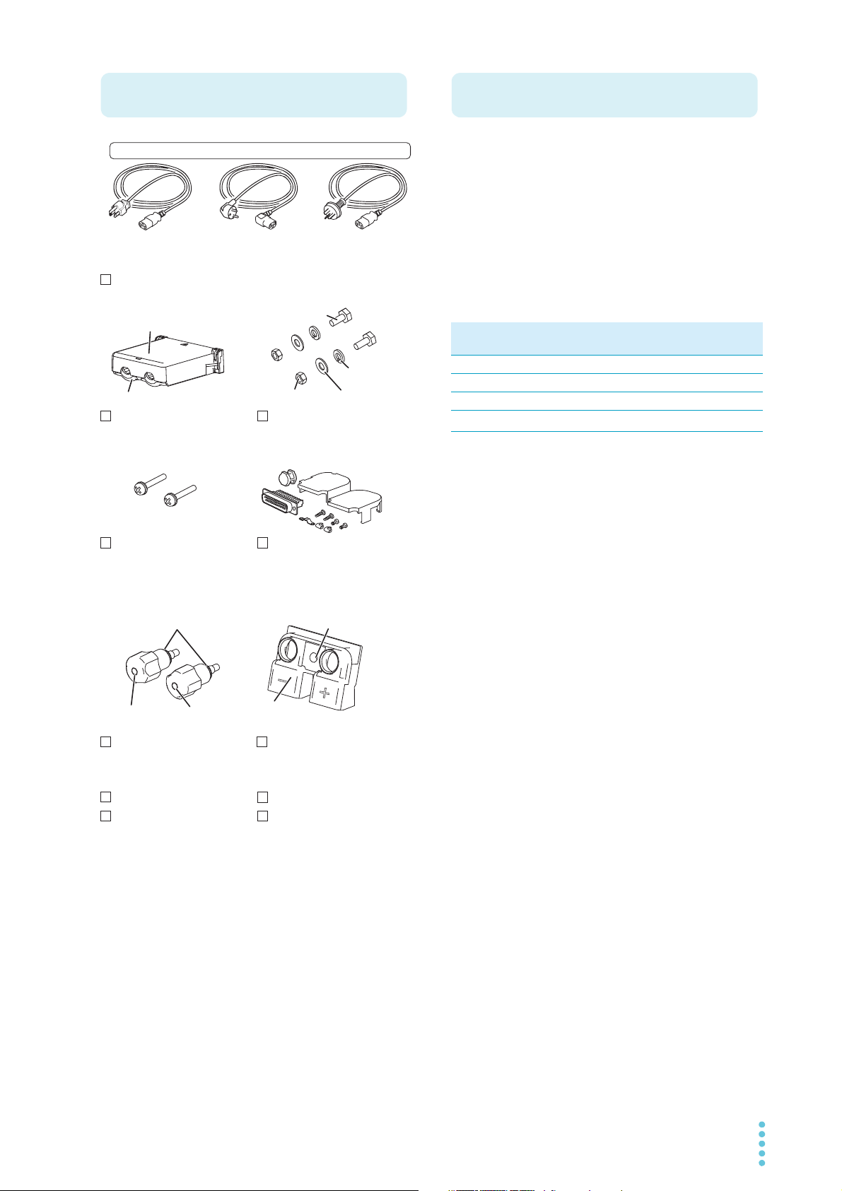
Accessories
Rear-panel load input
terminal cover ( 1 pc.)
Front-panel load input
terminal cover ( 1 pc.)
Front-panel load
input knob set (1 set)
Load input terminal
screw set (2 sets)
Power cord (1 pc., length: 2.5 m)
[M1-100-119]
[M5-101-008]
[M4-100-008]
CD-ROM (1 disk)
Setup Guide (1 pc.)
Safety Information (1 pc.)
Quick Reference
(Japanese (1 sheet),
English (1 sheet))
Plug: NEMA5-15
Rating: 125 Vac/10A
[85-AA-0004]
Plug: CEE7/7
Rating: 250 Vac/10A
[85-10-1070]
Plug: GB1002
Rating: 250 Vac/10A
[85-10-0790]
or or
[M5-100-008]
Cover
[Q1-500-161]
Screw [M8-600-021]
Top [Q1-500-156]
Bottom [Q1-500-157]
External control
connector kit (1 set)
[83-20-0190]
+ (red)
[N8-000-003]
– (black)
[N8-000-002]
The attached power cord varies depending on the shipment destination.
Screws for the rear-panel
load input terminal cover
(2 pcs.) [M3-112-018]
Washer [M9-000-013]
Spring washer [M5-103-001]
Product Overview
system designed to offer the highest levels of reliability
and safety. The electronic load contains a stable and highperformance current control circuit that enables highspeed load simulations. Designed to allow high-precision
current setting, it provides outstanding resolution.
Because the electronic load comes standard with
RS232C, USB, and LAN communication functions, it can
easily be incorporated into a wide range of inspection systems.
PLZ-5W series lineup
Model Maximum oper-
ating current
PLZ205W 40 A 1 V to 150 V 200 W
PLZ405W 80 A 1 V to 150 V 400 W
PLZ1205W 240 A 1 V to 150 V 1200 W
*1
PLZ2405WB
*1. PLZ1205W dedicated booster
480 A 1 V to 150 V 2400 W
Operating
voltage
Power
Features
In addition to basic constant current, constant resistance,
constant voltage, and constant power modes, the PLZ-5W
Series offers a variety of other functions. The PLZ-5W
series also provides better performance than previous
models.
High-speed response
The rise time has been improved from 10 µs to 5 µs.
Expanded voltage range
The minimum operating voltage has been improved
from 1.5 V to 1.0 V, offering support of low voltage input.
Arbitrary I-V characteristics mode
Arbitrary I-V characteristics mode that allows current to
be set arbitrarily in relation to voltage input. This mode
can be used for simulation of LED loads and the like.
Color liquid crystal display (LCD)
Allows easy-to-see display in color. The voltage value,
current value, power value, current capacity value (Ah),
and power capacity value (Wh) at the load input terminal
are indicated on the display.
Increased power capacity and current capacity
Power capacity and current capacity 1.2 times those of
previous models have been realized while keeping the
size unchanged.
Larger capacity achievable
Larger capacity can be achieved by connecting optional
boosters (PLZ2405WB) to the PLZ1205W. Up to four
booster units can be operated in parallel using a
PLZ1205W unit as the master unit (up to 10.8 kW,
2160 A).
Support of synchronized operation
Load on/off control and the execution of sequences can
be synchronized for multiple PLZ-5W units.
PLZ-5W User’s Manual 3
RS232C, USB, and LAN communication functions
Notations Used in This Manual
WARNING
CAUTION
Safety Precautions
Precautions Concerning
Installation Location
provided as standard
These functions allow easy incorporation into various
types of inspection systems.
GPIB function available as option*
Using the optional GPIB converter (p.171), the GPIB
function can be used via the RS232C or USB interface.
* Limitation apply to some of the functions.
When using this product, be sure to observe the “Safety
Precautions” in the Safety Information manual. The following precautions pertain only to this product.
• The rear panel may become hot during operation. If you
touch it, you may burn yourself.
• In this manual, electronic load PLZ205W, PLZ405W, or
PLZ1205W is sometimes referred to as PLZ-5W.
• The term “PC” is used to refer generally to both personal
computers and workstations.
• The term “DUT” is used to refer generally to a device
under test.
• The screen captures and illustrations used in this text
may differ from the actual items.
• The following markings are used in the explanations of
this text.
Indicates a potentially hazardous situation which, if
ignored, could result in death or serious injury.
Indicates a potentially hazardous situation which, if
ignored, may result in damage to the product or other
property.
Indicates information that you should know.
Indicates a reference manual (CD-ROM) containing
detailed information.
When installing this product, be sure to observe the “Precautions When Choosing the Installation Location” in the
Safety information manual. The following precautions pertain only to this product.
• When installing this product, be sure to observe the temperature and humidity ranges indicated below.
Operating temperature range: 0 °C to 40 °C
(32 °F to 104 °F)
Operating humidity range: 20 %rh to 85 %rh
(no condensation)
• When storing this product, be sure to observe the temperature and humidity ranges indicated below.
Storage temperature range: -20 °C to 70 °C
(-4 °F to 158 °F)
Storage humidity range: 90 %rh or less (no condensation)
• Do not install the product vertically.
It may cause injury to the operator or damage to the
product when it falls down.
>
Indicates the hierarchy of items you need to select. The
item to the left of this symbol indicates a higher level
item.
4 User’s Manual PLZ-5W

Contents
About the PLZ-5W Series Manuals ....................2
Accessories ........................................................3
Product Overview ...............................................3
Notations Used in This Manual...........................4
Safety Precautions .............................................4
Precautions Concerning Installation Location ....4
Component Names ............................................8
Installation and Preparation
Connecting the Power Cord .............................12
Checking Whether the Power Is On or Off .......13
Turning the power on............................................ 13
Turning the power off............................................ 13
Connecting to the DUT.....................................14
Connecting to the load input terminals on the rear
panel..................................................................... 15
Connecting to the load input terminals on the front
panel..................................................................... 17
Notes regarding load input terminals .................... 18
Turning the switching function on/off .................... 39
Timing of trigger signal output .............................. 39
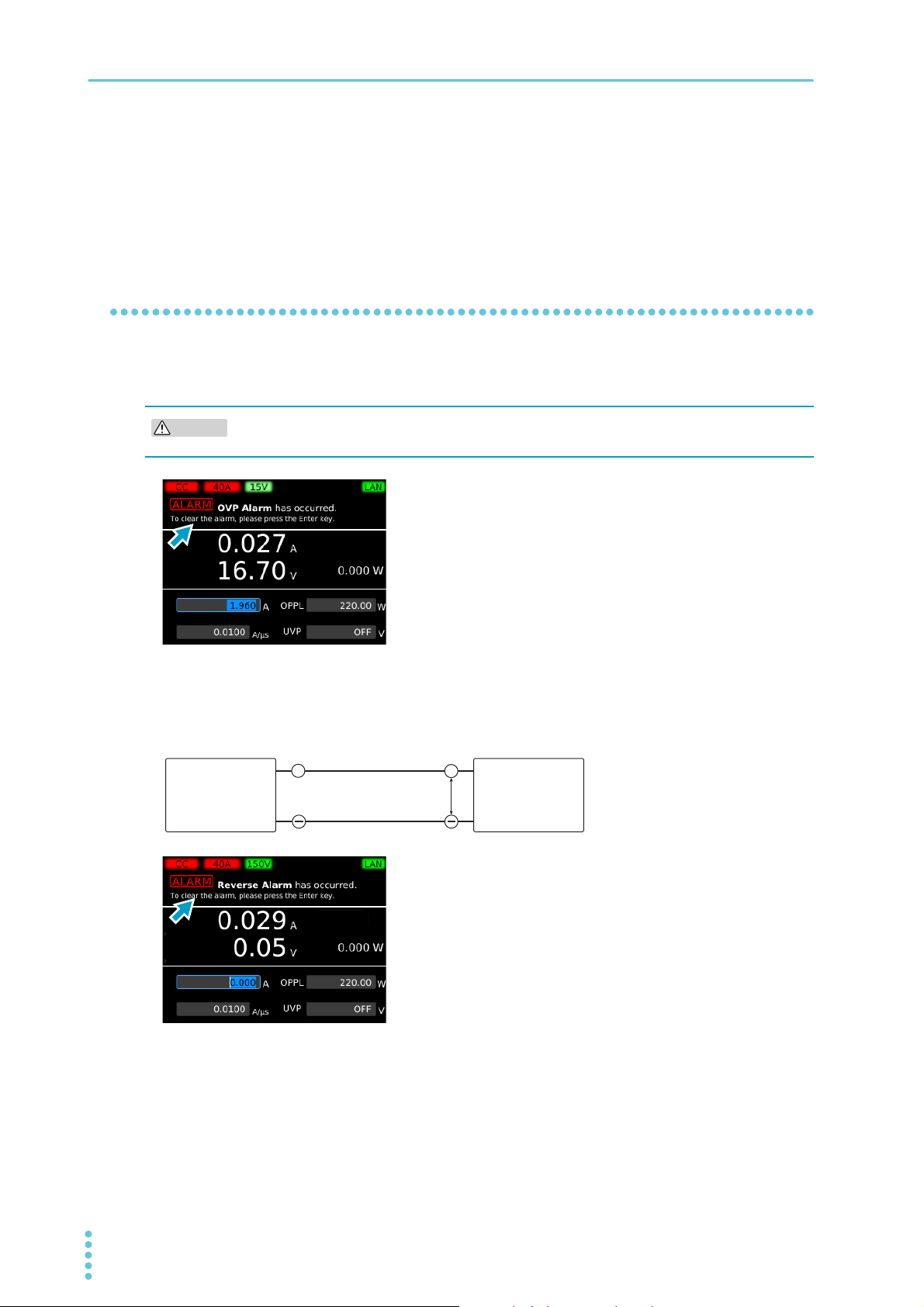
Alarm Function ................................................. 40
Alarm types and operation ................................... 40
Setting overcurrent protection (OCP) ................... 42
Setting overpower protection (OPP)..................... 43
Setting undervoltage protection (UVP)................. 44
Setting watchdog protection (WDP) ..................... 45
When an alarm occurs ......................................... 45
Clearing an alarm................................................. 46
Recording Measurements ................................ 47
Starting measurement recording .......................... 47
Obtaining measurements ..................................... 47
Setting recording conditions ................................. 48
Aborting a measurement recording ...................... 50
Recording Integrated Data............................... 51
Recording current capacity, power capacity, and
elapsed time ......................................................... 51
Showing or hiding integrated data........................ 53
Advanced Functions
Basic Functions
Panel Operations..............................................19
Switching the display ............................................ 19
Using the function keys ........................................ 20
Inputting numbers and characters ........................ 22
Changing values................................................... 23
Load On/Off ......................................................24
Setting the Operation Mode .............................25
Setting the operation mode .................................. 25
Setting the current in CC mode ............................ 26
Setting the conductance in CR mode ................... 26
Setting the voltage in CV mode ............................ 27
Setting the power in CP mode.............................. 27
Setting the load value in CC+CV mode ................ 28
Setting the load value in CR+CV mode ................ 29
Setting the load value in ARB mode..................... 30
Setting the Current Range and Voltage Range34
Setting the Slew Rate.......................................35
Setting the Short Function................................36
Switching Function ...........................................37
Setting the switching level .................................... 37
Setting the switching interval ................................ 38
Changing the Response Speed .......................54
Soft Start ..........................................................55
Remote Sensing............................................... 56
Connecting the sensing cables ............................ 56
Enabling or disabling remote sensing .................. 57
Auto Load Off Timer......................................... 58
Types of Memory ............................................. 59
ABC Preset Memories...................................... 60
Saving to ABC preset memories .......................... 61
Recalling ABC preset memory entries ................. 62
Setup Memory ..................................................63
How to view the setup memory edit screen.......... 63
Saving to the setup memory................................. 64
Checking the setup memory details ..................... 66
Recalling the setup memory ................................. 66
Synchronized Operation...................................67
Connection for synchronized operation................ 67
Synchronizing the load on/off operation ............... 69
Synchronizing measurement recording................ 70
Synchronizing the start of sequences .................. 71
Synchronizing the resuming of sequences........... 72
Aborting synchronized operation.......................... 72
Remote Control ................................................73
Releasing remote control ..................................... 73
PLZ-5W User’s Manual 5

Sequence Function
Overview of the Sequence Function................ 74
Programs and steps ..............................................74
Main functions .......................................................74
Program Configuration .................................... 75
How to view the program editing screen ...............75
Creating a program ...............................................75
Setting the number of loops ..................................76
Setting the voltage of CV mode addition (+CV) ....77
Setting protection functions ...................................78
Changing a program name ...................................79
Deleting a program................................................79
Setting Steps ................................................... 80
Creating steps .......................................................80
Deleting steps .......................................................83
Sequence Creation Tutorial............................. 84
Creating Program1 as a new program ..................84
Registering steps to Program1..............................85
Executing, Pausing, and Stopping Sequences 88
Executing a sequence ...........................................88
Pausing a sequence..............................................89
Aborting a sequence .............................................89
Controlling the start of sequences with triggers ....89
External Control
Preparation for External Control ...................... 91
Precautions for high-speed load simulations ........91
EXT CONT connector pin arrangement ................92
Connecting to the EXT CONT connector ..............93
Load Setting Control........................................ 95
Constant current (CC), constant resistance (CR), and
constant power (CP) control..................................95
Constant voltage (CV) control ...............................96
Controlling the current to be superimposed on the
constant current (CC)............................................97
Controlling Load On/Off................................... 98
Load on/off control input........................................98
Load-on status signal output .................................99
Current Range Control .................................. 100
Range control input .............................................100
Range status output ............................................100
Controlling Alarms ......................................... 101
Alarm input ..........................................................101
Alarm clearing input ............................................101
Alarm status output .............................................101
Trigger Input/Output ...................................... 102
Trigger input ........................................................102
Trigger output......................................................102
Digital I/O........................................................ 103
Using the Current Monitor Signal ...................104
Current monitor output ........................................104
Parallel Operation
Overview of Parallel Operation.......................105
Parallel Operation Using the Same Model .....106
Making connections for parallel operation ..........107
Performing parallel operation ..............................109
Slew rate and response speed settings during paral-
lel operation ........................................................109
Protection function during parallel operation (parallel
operation anomaly detection)..............................109
Canceling parallel operation ...............................110
System Settings
Displaying and Changing CONFIG Settings ..111
Remote sensing ..................................................111
Panel settings at startup .....................................112
Watchdog protection setting (WDP)....................112
Screen saver.......................................................113
Key lock ..............................................................114
Setting the beep sound .......................................115
Setting the DIGITAL2 signal input/output............115
Displaying/Changing the Interface Settings ...116
Resetting the interface settings...........................117
Returning the interface settings to the factory default
values..................................................................118
Displaying SCPI Errors...................................119
Setting the Date/Time.....................................120
Factory Default Settings and Reset Settings..121
Restoring the factory default settings..................121
Restoring the reset settings ................................122
Main settings at factory default and at reset .......123
Updating.........................................................125
Displaying the Device Information..................126
Maintenance
Inspection....................................................... 127
Overhaul .............................................................127
Backup battery replacement ...............................127
Calibration...........................................................127
6 User’s Manual PLZ-5W

Specifications
Ratings ............................................................... 128
Constant current (CC) mode .............................. 129
Constant resistance (CR) mode ......................... 130
Constant voltage (CV) mode .............................. 130
Constant power (CP) mode ................................ 131
Arbitrary I-V characteristics (ARB) mode............ 131
Measurement function ........................................ 131
Switching function............................................... 132
Slew rate............................................................. 133
Soft start ............................................................. 133
Alarm Function ................................................... 134
Sequence function.............................................. 134
Other functions ................................................... 135
Common specifications ...................................... 136
General specifications ........................................ 138
External dimensions ........................................... 139
Appendix
Troubleshooting ............................................. 173
Index ..............................................................175
Selecting the Load Cables .............................141
Methods to Stabilize Operation ......................143
Reducing the load cable inductance................... 143
Optimizing the response speed .......................... 144
Using remote sensing ......................................... 145
Slew Rate for Small Currents .........................146
Operating Area ...............................................147
Basic operation modes ....................................... 147
Operation of the constant current (CC) mode .... 148
Operation in constant resistance (CR) mode ..... 149
Constant power (CP) mode operation ................ 151
Constant voltage (CV) mode operation .............. 152
Operation when CV mode is added to CC mode 154
Operation when CV mode is added to CR mode 155
Operating area of each model ............................ 157
Response Time and Waveform When an OPP Is
Activated.........................................................160
Response time.................................................... 160
waveform ............................................................ 161
Operating Range during Parallel Operation ...163
Parallel operation using the same type of electronic
loads ................................................................... 163
Parallel operation using boosters ....................... 165
Options ...........................................................167
Rack adapters, brackets..................................... 167
GPIB converter (PIA5100).................................. 171
Parallel operation signal cable kit (PC01-PLZ-5W) ..
171
Low inductance cable ......................................... 171
Large current load cable..................................... 172
PLZ-5W User’s Manual 7
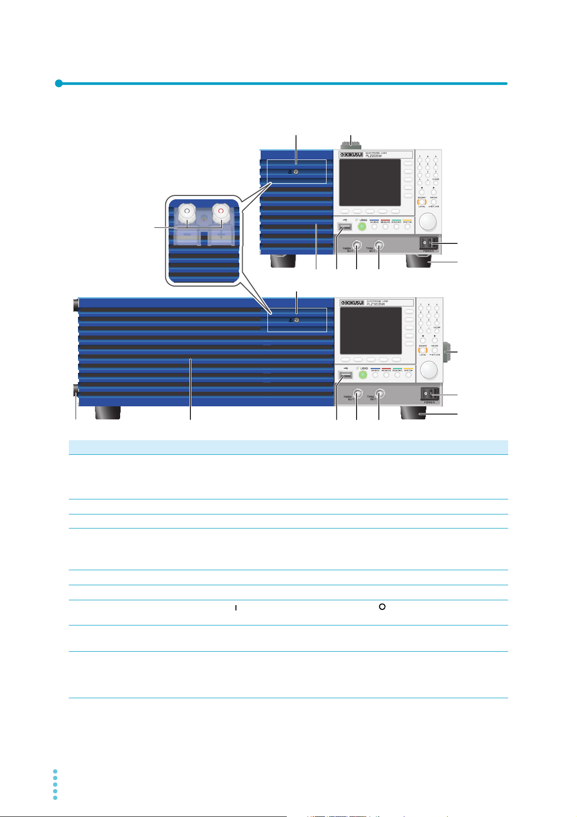
Component Names
PLZ205W
PLZ405W
(PLZ205W example)
PLZ1205W
12
2
345 6
8
7
34568
1
7
8
9
Front panel
No. Name Function See
Protection plate This plate protects the load input terminal on the front panel. The DUT and
1
Handle Handle for carrying the PLZ-5W.
2
Air inlet Inlet holes for cooling. –
3
USB connector (host) This connector is used to connect an external keyboard, save the setup
4
the PLZ-5W can be connected by removing the protection plate and attaching the front panel load input terminal cover. When not using the DC load
input terminal on the front panel, be sure to attach the protection plate.
memory, and perform updates.
I MON OUT connector Current monitor output terminal.
5
TRIG OUT terminal Trigger signal output terminal.
6
POWER switch
7
Feet PLZ205W/PLZ405W: 4 locations on bottom panel.
8
DC INPUT terminal on
9
the front panel
(Load input terminal on
the front panel)
Press the ( ) side to switch the power on, and the ( ) side to switch the
power off.
PLZ1205W: 4 locations on bottom panel, 4 locations on side panel.
Used for simple connection with the DUT. The specifications are for the load
input terminal on the rear panel and the load input terminal on the front panel
may not meet the specifications.
p.17
p.168
p.22
p.64
p.125
p.104
p.102
p.13
p.168
p.17
8 User’s Manual PLZ-5W

Controls
123
4
5
6
10 1211
9
8
7
No. Name Function See
Display area Displays the settings, measured values, and other information.
1
Function keys Each function key executes the item that is displayed above that key (func-
2
Sub-function keys Each sub-function key executes the item that is displayed to the left of that
3
Numeric keypad Enters values.
4
CLEAR key Deletes numbers/characters.
5
←/→ keys Move the cursor left and right. Select the left or right item.
6
ENTER key
7
KEYLOCK key
ESCAPE key
8
LOCAL key
Rotary knob Item selection. Inputs numbers/characters.
9
LOAD LED Lit when the load is on. –
10
LOAD key Turns the load on and off.
11
Menu key Switches the display.
12
SOURCE key Operation mode and load value settings, voltage and current range settings,
MEASURE key Measurement function, measurement trigger function, integrated data
SEQUENCE key Functions related to sequence.
SYSTEM key Remote sensing, system settings, interface settings, setup memory, SCPI
tion area).
key (sub-function area).
Confirms the input value when performing numeric keypad input. Confirmation after selection of setting item. Hold down to lock the keys.
Cancels numeric/character input. Closes the window.
Returns remote control to panel operation.
slew rate, short, switching, alarm, response speed, soft start, auto load off
timer, ABC preset memories, load on/off synchronization, measurement
recording synchronization, sequence synchronization, sequence start trigger
setting, external control.
recording/display, etc.
error display, date setting, restore factory default setting, update, device
information display.
p.10
p.20
p.20
p.22
p.22
p.22
p.22
p.114
p.22
p.73
p.22
p.24
p.19
–
p.47
p.51
p.74
p.111
PLZ-5W User’s Manual 9

Display
1
10
11
12
13
234675
8
9
No. Name Function See
Selected operation mode. Displays the selected operation mode.
1
Current range Displays the current range.
2
Voltage range Displays the voltage range.
3
Remote Indicates that the product is being controlled remotely.
4
Operation mode in use Displays the currently running operation mode.
5
LAN Displays the status of the LAN connection.
6
Green: Communication enabled. Orange: Preparing for communication.
Red: Not connected.
Icon –
7
Indicates that the switching function is currently being used.
Indicates that measured values are being recorded.
Indicates that remote sensing is in progress.
//
Sub-function area Indicates that execution is possible with the keys (sub-function keys) in the
8
Function area Indicates that execution is possible with the keys (function keys) at the bot-
9
Message area Displays alarm messages.
10
Measured values Displays the current, voltage, and power values. The load input ratio for the
11
Integrated data Displays the integrated data when integrated data display is enabled.
12
Value Displays load values (current, conductance, voltage, power) and other set-
13
Indicates that key lock is on. The key lock level is displayed numerically.
Sequence in progress.
Indicates that an SCPI error has occurred. The number of error incidents
(up to 16) is displayed numerically.
right side of the display.
tom of the display.
rating of each range is displayed in bar graph form under the current value
and voltage value.
tings such as slew rate and alarm operating conditions.
p.25
p.34
p.34
p.73
p.25
–
p.39
p.47
p.56
p.114
p.88
p.119
p.20
p.20
p.40
–
p.53
–
10 User’s Manual PLZ-5W
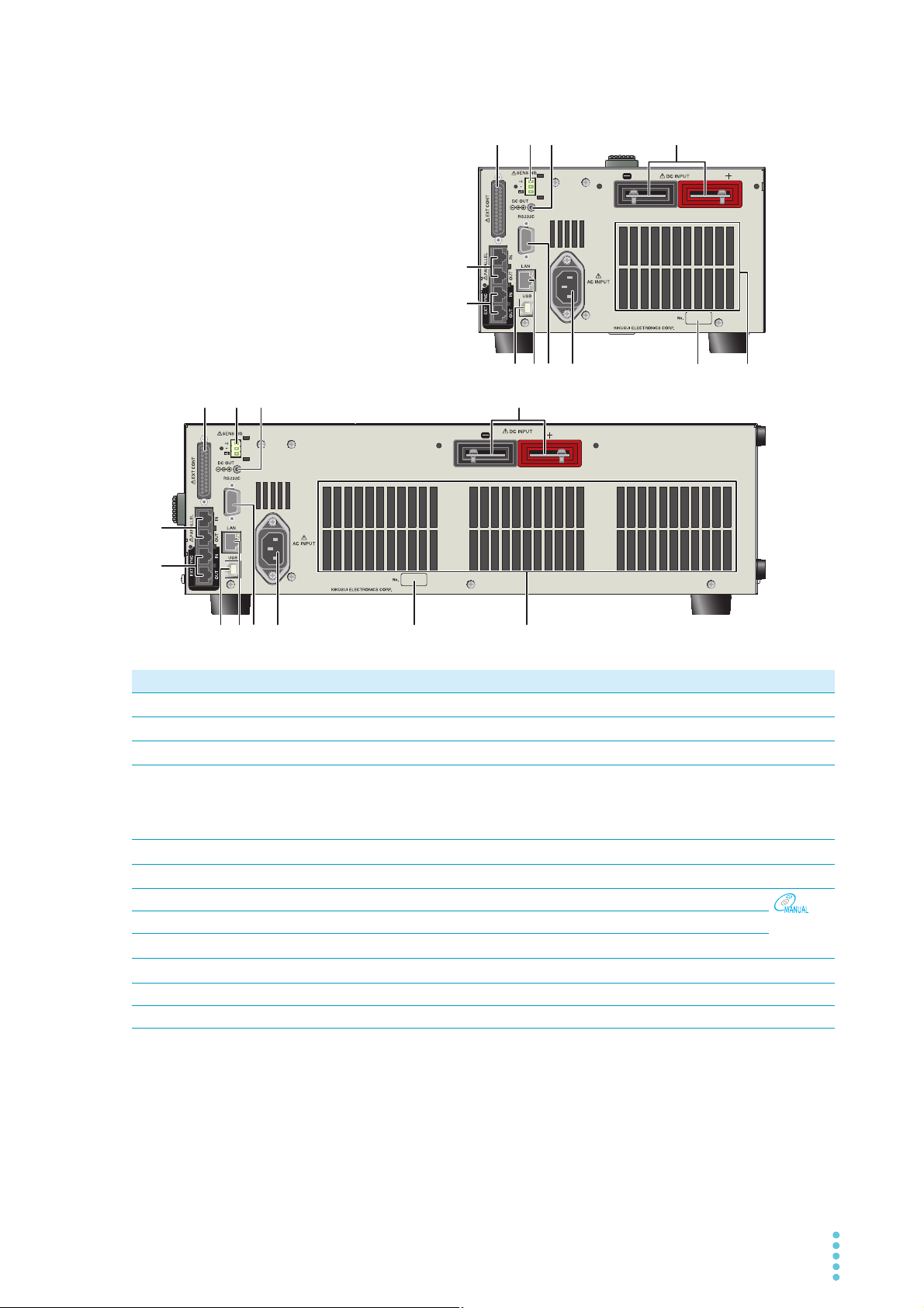
Rear panel
PLZ205W
PLZ405W
(PLZ205W example)
123
123
5
4
8 9 10 11 12
12
89 10 11
6
7
6
7
5
4
PLZ1205W
No. Name Function See
EXT CONT connector External control connector. A cover for the pins is provided.
1
SENSING connector Remote sensing connector.
2
DC OUT connector Used during GPIB converter (option) use.
3
DC INPUT terminal on
4
the rear panel
(load input terminal on
the rear panel)
PARALLEL connector Connector for parallel operation.
5
EXT SYNC port Connector for synchronized operation.
6
7
8
9
10
11
12
USB port (device) USB port for remote control.
LAN port LAN port for remote control.
RS232C port RS232C port for remote control.
AC INPUT connector Power inlet.
Serial number PLZ-5W manufacturing number. –
Air outlet Air outlet for cooling. –
Used to connect the DUT and the PLZ-5W.
p.91
p.56
p.171
p.14
p.106
p.67
Interface
Manual
p.12
PLZ-5W User’s Manual 11

Installation and Preparation
WARNING
Connect to a properly grounded outlet.
Connecting the Power Cord
Risk of electric shock.
• The PLZ-5W conforms to IEC Safety Class I (equipment that has a protective conductor terminal). Be sure to earth ground the product to prevent electric shock.
• The PLZ-5W is grounded through the power cord ground wire. Connect the protective conductor terminal to earth ground.
• Use the included power cord to connect to the AC line.
If the supplied power cord cannot be used because the rated voltage or the plug shape is
incompatible, have a qualified engineer replace it with an appropriate power cord that is
3 m or less in length. If obtaining a power cord is difficult, contact your Kikusui agent or
distributor.
• The power cord with a plug can be used to disconnect the PLZ-5W from the AC power line
in an emergency.
• Secure adequate space around the power cord plug. Do not insert the power cord plug
into an outlet that is difficult to access or place objects around the power cord plug that will
make plugging and unplugging difficult.
• Do not use the supplied power cord with other instruments.
The PLZ-5W conforms to IEC Overvoltage Category II (energy-consuming equipment that is supplied from
a fixed installation).
Turn the POWER switch off ( ).
1
Check that the AC power line meets the nominal input rating of the PLZ-5W.
2
The PLZ-5W can receive a nominal line voltage in the range of 100 Vac to 240 Vac at 50 Hz or
60 Hz. (Frequency range: 47 Hz to 63 Hz)
Connect the power cord to the AC INPUT inlet on the rear panel.
3
Connect the power cord plug to a properly grounded outlet.
4
This completes the setting.
12 User’s Manual PLZ-5W
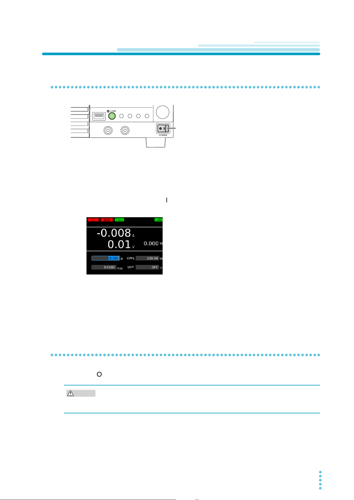
Installation and Preparation
POWER switch
CAUTION
Checking Whether the Power Is On or Off
Turning the power on
Check that the power cord is connected correctly.
1
Check that nothing is connected to the DC INPUT (load input) terminals on the front
2
and rear panels.
Turn the POWER switch on ( ).
3
The PLZ-5W turns on, and the display lights.
If you notice strange sounds, unusual odors, fire, or smoke around or from inside the PLZ-5W, turn the
POWER switch off, or remove the power cord plug from the outlet.
By factory default, the panel settings immediately before the POWER switch is turned off are saved. When
you turn the power on, the PLZ-5W starts in the same state as it was in the last time it was turned off.
(However, the load setting is always Load Off.)
The panel setting state at startup can be changed (p.112).
Turning the power off
Press the ( ) side of the POWER switch to turn the power off.
If you want to turn the POWER switch back on, wait at least 5 seconds after the fan stops.
Repeatedly turning the POWER switch on and off at short intervals will shorten the service
life of the POWER switch and the internal input fuse.
PLZ-5W User’s Manual 13

Installation and Preparation
WARNING
CAUTION
Connecting to the DUT
The PLZ-5W has load input terminals on both its front and rear panels. The specifications of the PLZ-5W
are for the load input terminals on the rear panel.
For information on selecting load cables, refer to “Selecting the Load Cables” (p.141) in the “Appendix”.
Large current load cables are available as options. For details, see the Large Current Load Cable Manual
in the included CD-ROM.
Risk of electric shock.
• Do not touch load input terminals when the output is turned on.
• The load input terminals on the front panel are connected internally to the load
input terminals on the rear panel. The voltage applied to the terminal on one side
appears directly at the terminal on the other side.
Risk of damage.
• Do not connect the DUT to the load input terminals while the product’s load is turned on.
• Do not connect electronic loads to the load input terminals on the front panel and those on
the rear panel at the same time.
• Do not invert the polarity when connecting. An overcurrent might flow when the load is
turned on.
To avoid overheating, observe the following precaution.
• Use the supplied screws to connect the cables with crimping terminals.
14 User’s Manual PLZ-5W
Installation and Preparation | Connecting to the DUT
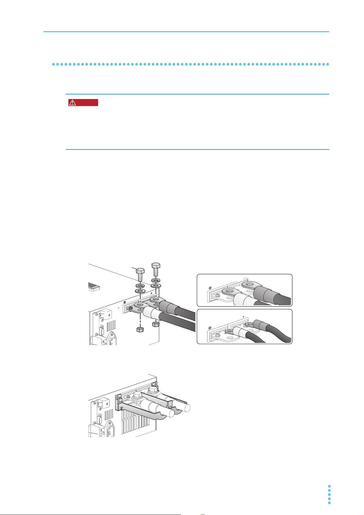
WARNING
Orientation of crimping terminals
(1) Basic orientation
(2) If crimping terminal is small
Bolt (M10)
Connecting to the load input terminals on the rear panel
Connect the DUT to the load input terminals on the rear panel.
Risk of electric shock.
• Be sure to attach the cover for the load input terminals on the rear panel.
• Attach the protection plate or cover for the load input terminals on the front panel
also to the load input terminals on the front panel. The voltage applied to the load
input terminals on the rear panel appears at the load input terminals on the front
panel.
Turn the load off.
1
Turn off the output of the DUT.
2
Attach crimping terminals to the load cables.
3
The load input terminals on the rear panel have bolt (M10) holes for connecting the load cables.
Attach the appropriate crimping terminals to the cables.
Connect the load cables to the load input terminals on the rear panel using the
4
included load input terminal screw set.
To prevent interference with the cover for the load input terminals on the rear panel, basically connect the crimping terminals in orientation (1) in the figure. If the crimping terminals are small and
cannot be connected in orientation (1), connect them in orientation.
Place the bottom half of the cover for the load input terminals on the rear panel
5
underneath the cables connected to the load input terminals.
PLZ-5W User’s Manual 15
Installation and Preparation | Connecting to the DUT
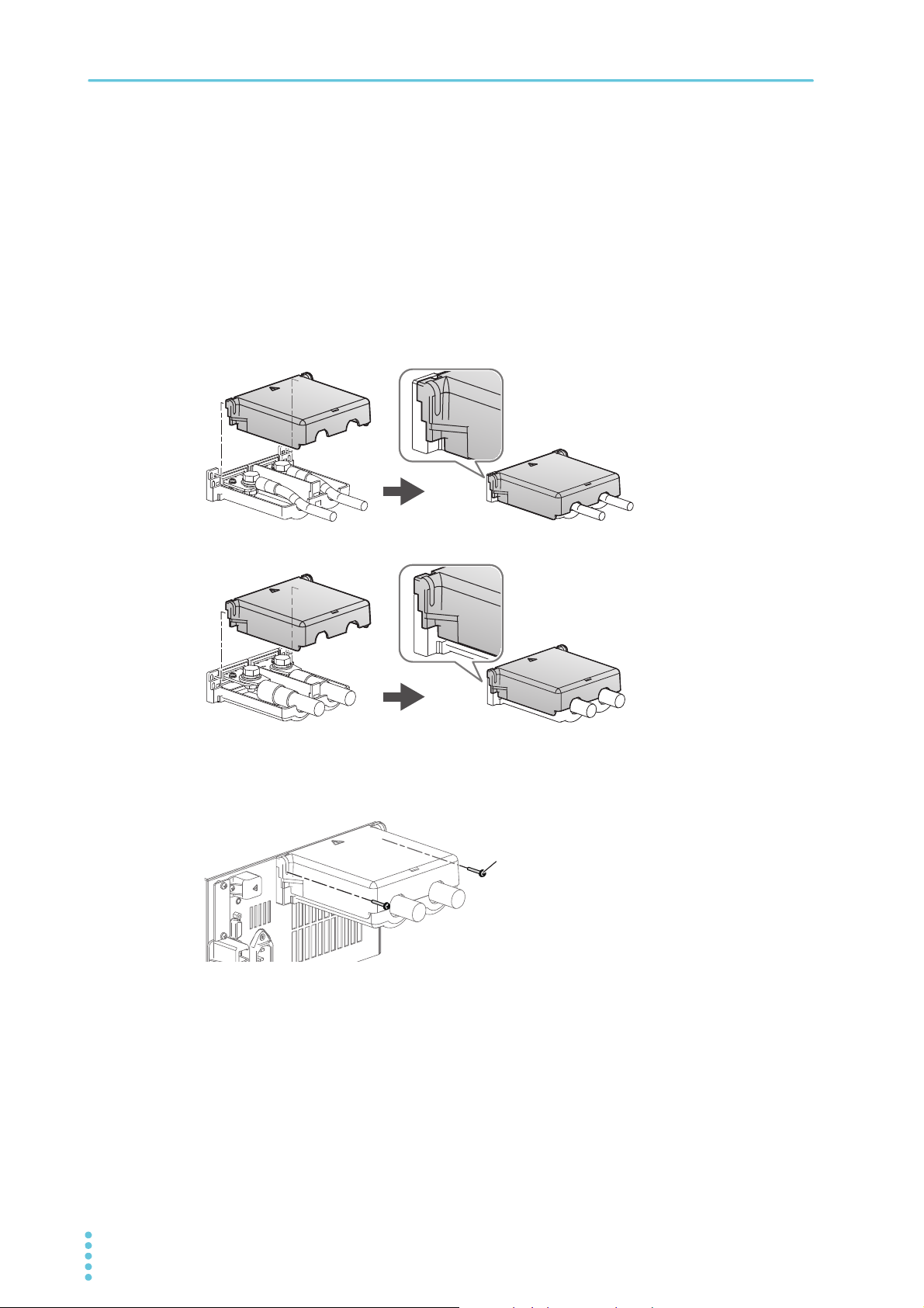
)RUWKLQORDGFDEOHVXSWRĭ
)RUWKLFNORDGFDEOHVĭWRĭ
M318
Align the tabs of the top cover for the load input terminals on the rear panel with
6
those of the bottom cover.
Align the tabs of the load input terminal cover according to the load cable diameter.
You can adjust the diameter of the holes that the load cables pass through by changing the position that the top and bottom covers are put together. There are two available positions. Use the
appropriate position for the load cables that you are using.
• For cables up to ø10 mm: Put the top and bottom load input terminal covers together so that the
hole diameter is small.
• For cables that are between ø10 and 20 mm: Put the top and bottom load input terminal covers
together so that the hole diameter is large.
Push the cover for the load input terminals on the rear panel against the panel, and
7
fasten it with the included screws.
Make sure that the screws are securely fastened.
Connect the load cables to the output terminals of the DUT.
8
Connect the positive (+) polarity of the load input terminal on the rear panel to the positive (+)
polarity of the DUT, and the negative (-) polarity of the load input terminal on the rear panel to the
negative (-) polarity of the DUT.
This completes the connections.
16 User’s Manual PLZ-5W
Installation and Preparation | Connecting to the DUT
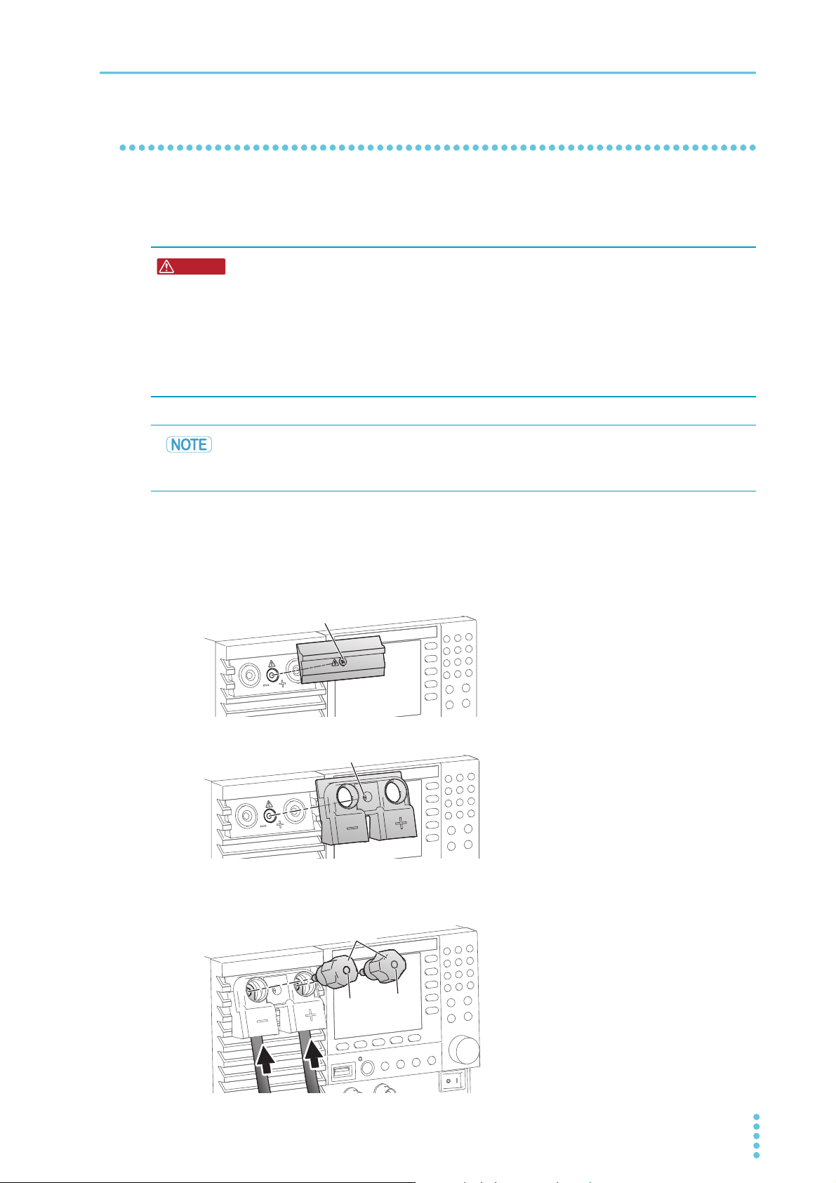
WARNING
M3×10
M3×10
KnobKnob
Black (-)Black (-)
Red (+)Red (+)
Connecting to the load input terminals on the front panel
The load input terminals on the front panel enable you to easily connect the DUT to the PLZ-5W. The
specifications of the PLZ-5W are for the load input terminals on the rear panel. The load input terminals on
the front panel may not meet the specifications.
Risk of electric shock.
• Attach insulation caps to the crimping terminals.
• When not using the load input terminals on the front panel, be sure to attach the
cover for the load input terminals on the front panel or the protection plate.
• Attach the cover for the load input terminals on the rear panel also to the load input
terminals on the rear panel. The voltage applied to the load input terminals on the
front panel appears at the load input terminals on the rear panel.
The rated current value of the load input terminals on the front panel of the PLZ1205W is
80 A. When a current of 80 A or more flows to the load input terminals on the front panel, an
alarm occurs and the load turns off.
Turn the POWER switch off.
1
Turn off the output of the DUT.
2
Remove the protection plate of the load input terminals on the front panel.
3
Attach the cover for the load input terminals on the front panel.
4
Insert the load cables from the bottom and tighten the accessory knobs to fix the
5
cables in place.
Keep the removed protection plate and
screws in a safe place. By attaching the protection plate when not using the load input terminals on the front panel, the PLZ-5W can be
used in a safe and compact manner.
PLZ-5W User’s Manual 17
Installation and Preparation | Connecting to the DUT
CAUTION
DUT
PLZ-5W
9GF
+ +
Connect the load cables to the output terminals of the DUT.
6
Connect the positive (+) polarity of the load input terminal on the front panel to the positive (+)
polarity of the DUT, and the negative (-) polarity of the load input terminal on the front panel to the
negative (-) polarity of the DUT.
This completes the connections.
Notes regarding load input terminals
Do not apply overvoltage to the load input terminals
Risk of damage. Do not apply a voltage that exceeds 150 Vdc to the load input terminals.
When an overvoltage of 165 V is applied when the voltage range is
150 V, or when an overvoltage of 16.5 V is applied when the voltage range is 15 V, a beeping sound is emitted and an alarm
appears. If this happens, immediately lower the voltage of the DUT.
Match the wiring polarity with that of the DUT
Be careful to match the polarities of the load input terminals with those of the DUT during connection.
If a reverse voltage of 0.6 V or higher is applied, or a reverse current (approximately -1 % of the range rating) flows, a beeping
sound is emitted and an alarm appears. If this happens, immediately turn off the POWER switch of the DUT.
18 User’s Manual PLZ-5W
Basic Functions
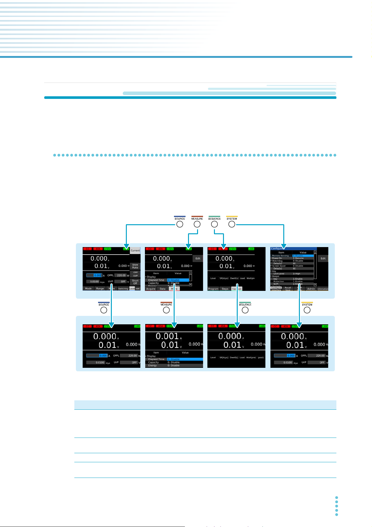
Menu key
SOURCE screen MEASURE screen SEQUENCE screen SYSTEM screen
Main display
Function display
**
Panel Operations
This chapter explains the front panel operations in general.
Switching the display
There are two display modes: function display and main display. The function display shows functions that
can be executed on each screen. The main display shows measured values with large numbers.
Pressing a menu key shows the function display of the corresponding menu screen. Pressing the same
menu key again on the function display switches the display to the main display.
* On screens that do not show measured values (the screen that appears when the Program or Step
key is pressed on the SEQUENCE screen or the SYSTEM screen), the display switches to the main
PLZ-5W User’s Manual 19
display of the screen that showed measured values last.
Menu key Available functions
SOURCE Operation mode and load value settings, voltage and current range settings, slew rate,
short, switching, alarm, response speed, soft start, auto load off timer, ABC preset memories, load on/off synchronization, measurement recording synchronization, sequence synchronization, sequence start trigger setting, external control.
MEASURE Measurement recording, trigger settings for measurement recording, integrated data
recording, integrated data display, measurement synchronization.
SEQUENCE Sequencing, synchronizing the start of sequences.
SYSTEM Remote sensing, setup memory, system settings, interface settings, SCPI error display,
date/time setting, restore factory default setting, update, device information display.

Basic Functions | Panel Operations
Function keys
Sub-function keys
Sub-function area
Function area
Selected function
Ex:
Displayed as “Range”
Displayed as “Level” when
the level function is in use
Using the function keys
On the function display (p.19), the available functions are shown in the function area and sub-function
area. You can execute or select the functions by pressing the corresponding function key or sub-function
key.
The selected function is shown with a light gray background.
If two or more functions that can be used with a single function key are shown, you can switch between the
functions by repeatedly pressing the function key.
Key names
In this document, individual function keys and sub-function keys are distinguished by indicating the function names shown in the function area or sub-function area as the key names. If there are two or more
functions shown, the name of the function to use is indicated as the key name.
20 User’s Manual PLZ-5W
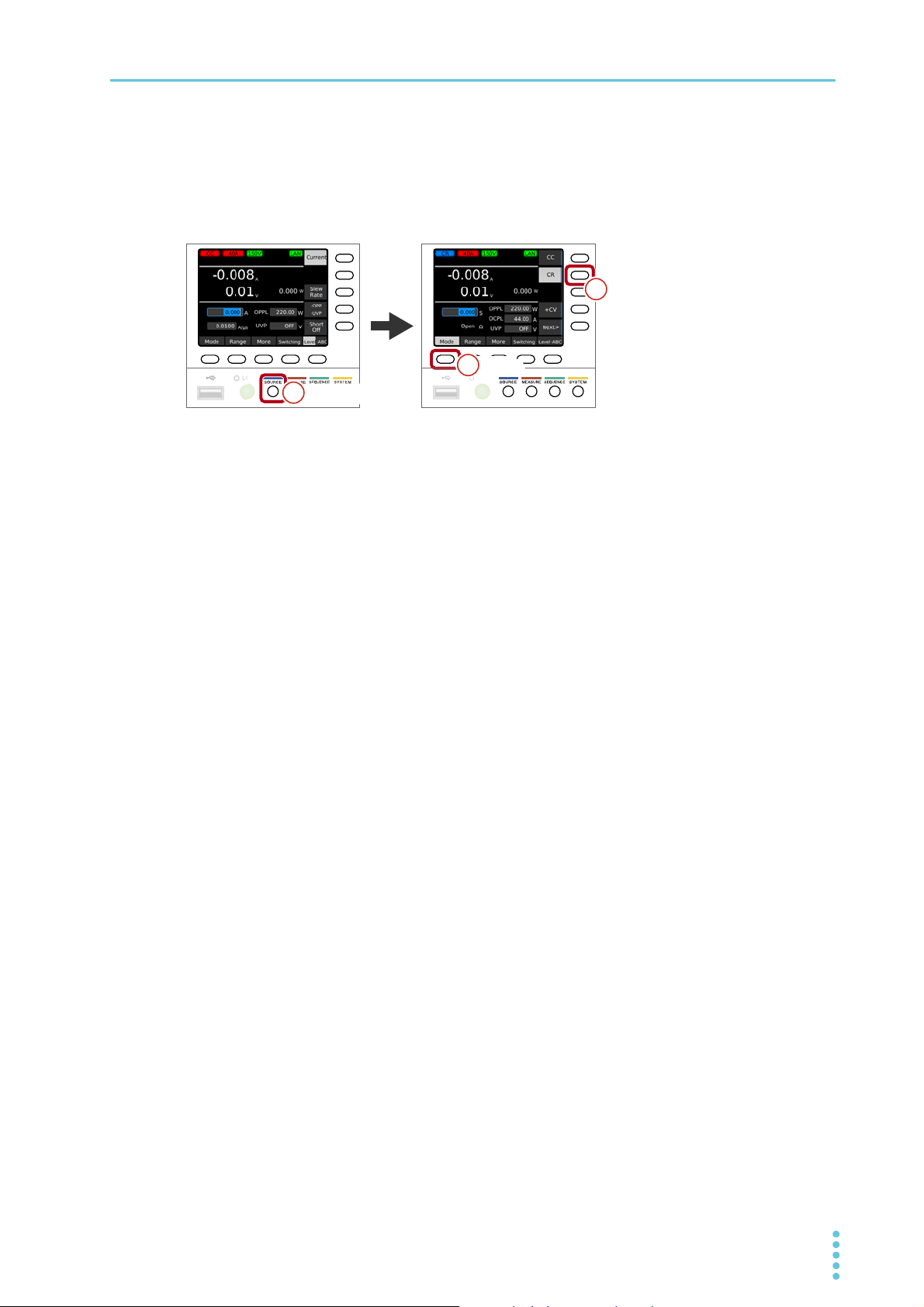
Basic Functions | Panel Operations
O
SOURCESOURCE11
ModeMode
22
CRCR
33
Operation example (Selection of constant resistance mode)
Press SOURCE, Mode, and then CR.
1
In the above step example, press the buttons in the following order.
PLZ-5W User’s Manual 21
Basic Functions | Panel Operations
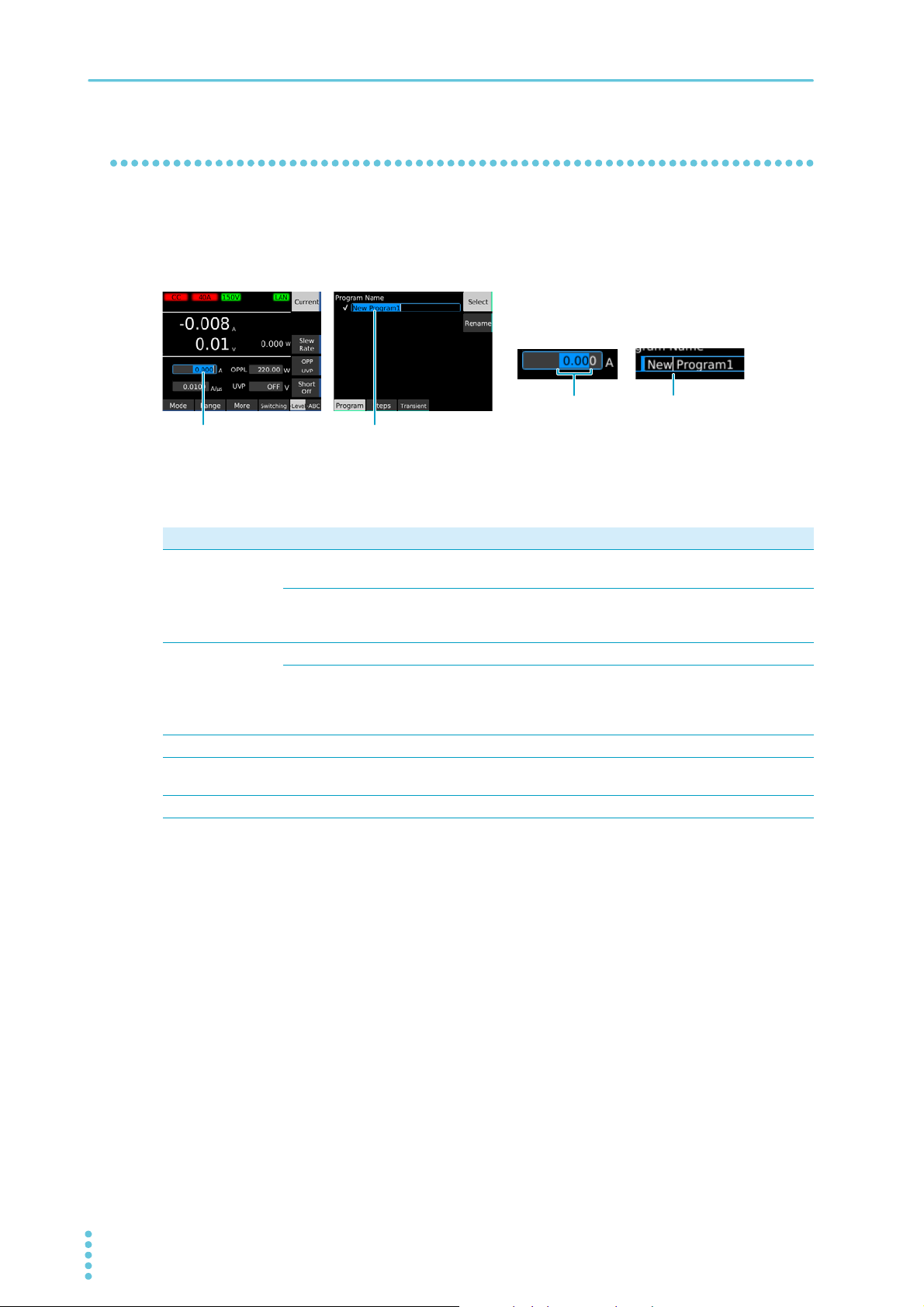
Range selection
Input area (value)
Cursor
Input area (character)
Inputting numbers and characters
You can enter numbers and characters in input areas from the front panel or external keyboard. Number
input and character input switch automatically according to the input area.
If numbers or characters are selected in an input area, they can be changed. If only a cursor is shown in
an input area, you can enter characters or numbers at the cursor position.
Entering from the front panel
Purpose Operation Description
Numeric input Numeric keypad You can enter numbers and a decimal point. Following input, press
the ENTER key to confirm the value.
Rotary knob You can enter numbers. Turn clockwise to increase the value and
counterclockwise to decrease. The value is confirmed immediately
upon input.
Character input Numeric keypad You can enter numbers and dots.
Rotary knob Turn clockwise to enter characters in the following order: space,
uppercase letters, lowercase letters, numbers, and symbols. Turn
counterclockwise to enter character in reverse order. To enter the next
character, press the ← or → key to move the cursor.
Cursor movement ←/→ keys Changes the number of digits or input position.
Delete CLEAR key Deletes the number or character on the left of the cursor or the
selected range.
Cancel ESCAPE key Cancels numeric/character input.
Entering from an external keyboard
You can enter numbers/characters if you connect a keyboard to the USB port on the front panel. Use the
arrow keys to move the cursor, the Backspace and Delete key to delete numbers and characters, the
Escape key to cancel input, the Enter key to confirm, and the Tab key to move between input items.
22 User’s Manual PLZ-5W
Changing values
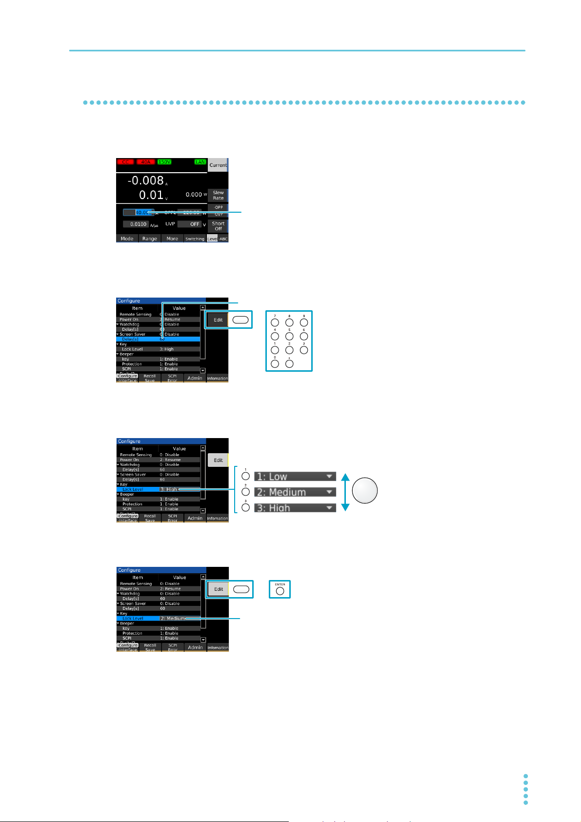
Use the numeric keypad or the rotary knob to change the value.
Pressing Edit or a numeric key makes it possible to edit the value.
If there are multiple items when settings are being changed, use the numeric
keypad or the rotary knob to select the item.
Use Edit or ENTER to confirm the value.
To change a selected value (e.g., load value), use the numeric keypad or rotary knob. If you enter a value
with the numeric keypad, following input, press the ENTER key to confirm the value.
On screens in which “Edit” is shown in the sub-function area, use the rotary knob to select the item you
want to change, and then press the Edit key or a numeric key to start changing the value. Procedures
using the Edit key are provided in this document.
Basic Functions | Panel Operations
When changing a setting, if there are multiple items you can choose from, select a number in front of the
item name using the numeric keypad, or select the item using the rotary knob. Procedures using the rotary
knob are provided in this document.
To confirm a value you entered, press the Edit or ENTER key. Procedures using the ENTER key are provided in this document.
PLZ-5W User’s Manual 23
Basic Functions
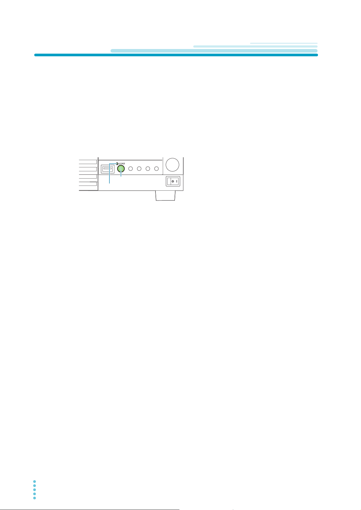
LOAD key
Load-on LED
Load On/Off
“Load on” refers to a condition in which a current is running through the PLZ-5W. “Turning the load on”
refers to the operation of running a current through the PLZ-5W.
Conversely, “load off” refers to a condition in which a current is not running through the PLZ-5W. “Turning
the load off” refers to the operation of stopping a current from running through the PLZ-5W.
Turning the PLZ-5W’s load on and off is done with the LOAD key.
Press LOAD.
1
The value switches between load on and load off each time you press the key.
In the load on state, the load on LED lights.
In the load off state, the load on LED turns off.
Controlling load on/load off externally
Load on/load off can be controlled using an external signal (p.98).
Gradually increasing the input current of the PLZ-5W
In constant current (CC) mode, you can set to slowly increase the input current (Soft start) (p.55).
Turning off the load after a specified time elapses
When performing battery or capacitor discharge tests, it is convenient to use the function to automatically turn off the load after a specified time elapses (auto load off timer) (p.58).
24 User’s Manual PLZ-5W
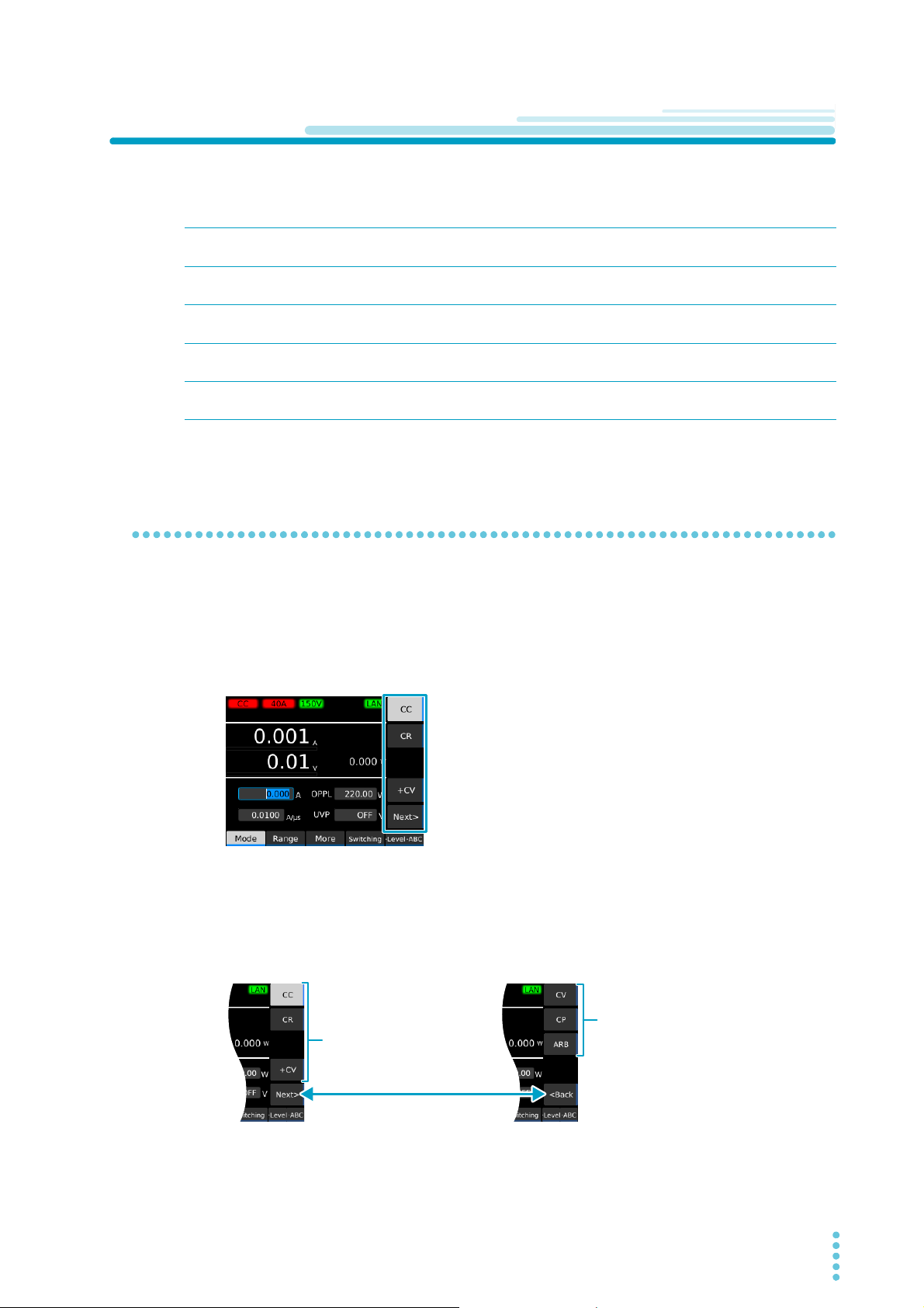
Setting the Operation Mode
Select the
operation mode
(CC, CR, +CV).
Select the
operation mode
(CV, CP, ARB).
Switches the operation mode display
The PLZ-5W has the following five operation modes. Mode switching can be done only while the load is
off.
Basic Functions
Constant current (CC)
mode
Constant resistance (CR)
mode
Constant voltage (CV)
mode
Constant power (CP)
mode
Arbitrary I-V Characteristics (ARB) Mode
CV mode can be added to CC mode (CC+CV) and CV to CR mode (CR+CV).
A current value is specified and the current is kept constant even when the voltage
changes.
A conductance value is specified and the PLZ-5W sinks current proportional to the
voltage variation.
A voltage is specified and the PLZ-5W sinks current so that the voltage at the load
input end of the PLZ-5W is constant.
A voltage is specified and the PLZ-5W sinks current so that the power consumed
inside the electronic load is constant.
The desired load characteristics can be set by specifying multiple arbitrary voltage
values and current values as I-V characteristics.
Setting the operation mode
You can set +CV regardless of whether the load is on or off. You can set other modes only when the load
is off.
Press SOURCE and then Mode.
1
The operation mode is shown in the sub-function area.
Use the sub-function keys to select the operation mode.
2
To set CC+CV, select CC and +CV.
To set CR+CV, select CR and +CV.
If the operation mode you want to select is not shown, press Next or Back to switch the operation
mode display.
“CC,” “CR,” “CV,” “CP,” “CC+CV,” “CR+CV,” or “ARB” appears in the upper left of the display
depending on the selected operation mode.
This completes the setting.
PLZ-5W User’s Manual 25
Basic Functions | Setting the Operation Mode
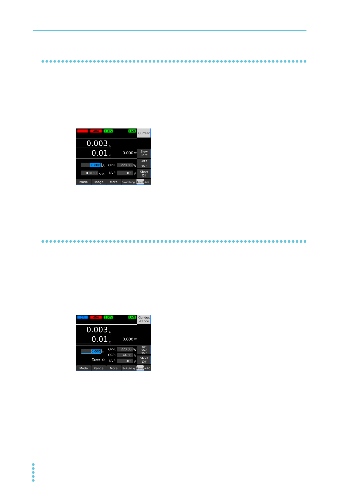
Setting the current in CC mode
In CC mode, the current is kept constant even when the voltage changes.
For details on CC mode, see “Operation of the constant current (CC) mode” (p.148).
Set the operation mode to CC mode (p.25).
1
Press Level and then Current.
2
Use the numeric keypad or the rotary knob to enter the current value.
3
This completes the setting. The current value can be changed even while the load is turned on.
Setting the conductance in CR mode
In CR mode, the PLZ-5W sinks current proportional to the voltage variation.The resistance calculated from
the conductance can also be displayed. (Conductance [S] = 1/resistance [Ω])
For details on CR mode, see “Operation in constant resistance (CR) mode” (p.149).
Set the operation mode to CR mode (p.25).
1
Press Level and then Conductance.
2
Use the numeric keypad or the rotary knob to enter the conductance value.
3
This completes the setting. The conductance value can be changed even while the load is turned
on.
26 User’s Manual PLZ-5W
Setting the voltage in CV mode
In CV mode, the PLZ-5W runs current so that the voltage at the load input end of the PLZ-5W is constant.
For details on CV mode, see “Constant voltage (CV) mode operation” (p.152).
Set the operation mode to CV mode (p.25).
1
Press Level and then Voltage.
2
Basic Functions | Setting the Operation Mode
Use the numeric keypad or the rotary knob to enter the voltage value.
3
This completes the setting. The voltage value can be changed even while the load is turned on.
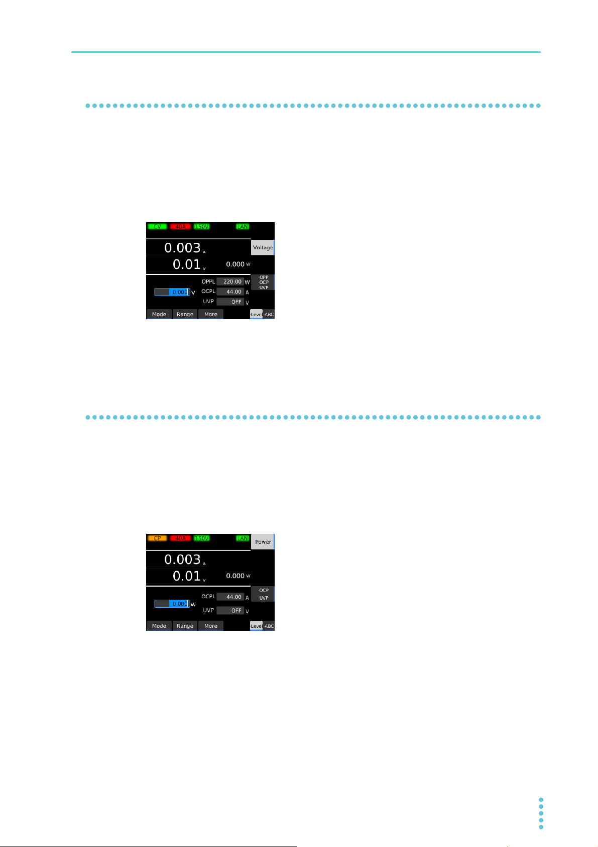
Setting the power in CP mode
In CP mode, the PLZ-5W runs current so that the consumed power is constant.
For details on CP mode, see “Constant voltage (CV) mode operation” (p.152).
Set the operation mode to CP mode (p.25).
1
Press Level and then Power.
2
Use the numeric keypad or the rotary knob to enter the power value.
3
This completes the setting. The power value can be changed even while the load is turned on.
PLZ-5W User’s Manual 27
Basic Functions | Setting the Operation Mode
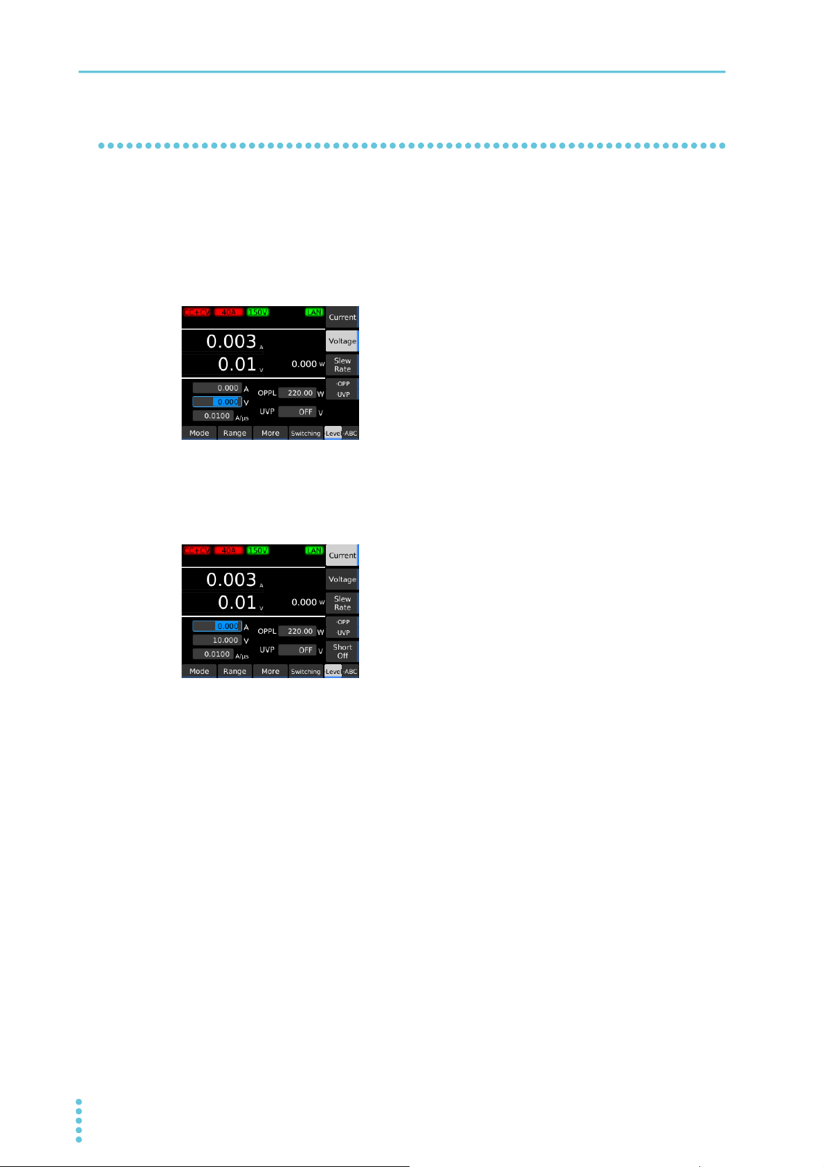
Setting the load value in CC+CV mode
You can add CV mode in CC mode.
For details on CC+CV mode, see “Operation when CV mode is added to CC mode” (p.154).
Set the operation mode to CC+CV mode (p.25).
1
Press Level and then Voltage.
2
Use the numeric keypad or the rotary knob to enter the voltage value.
3
This sets the voltage value.
Press Current.
4
Use the numeric keypad or the rotary knob to enter the current value.
5
This sets the current value. The voltage and current values can be changed even while the load is
turned on.
This completes the setting.
28 User’s Manual PLZ-5W
Basic Functions | Setting the Operation Mode
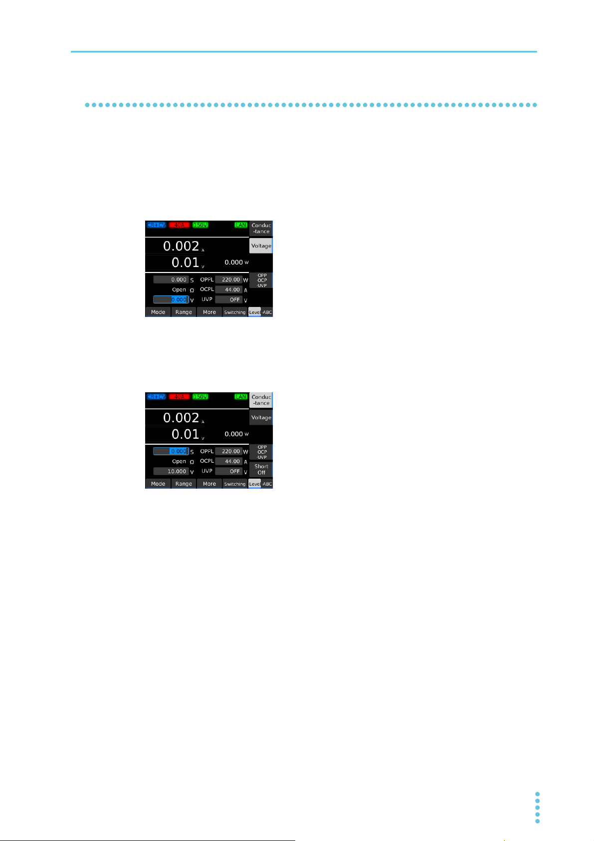
Setting the load value in CR+CV mode
You can add CV mode in CR mode. CV mode can be added even while the load is turned on.
For details on CR+CV mode, see “Operation when CV mode is added to CR mode” (p.155).
Set the operation mode to CR+CV mode (p.25).
1
Press Level and then Voltage.
2
Use the numeric keypad or the rotary knob to enter the voltage value.
3
This sets the voltage value.
Press Conductance.
4
Use the numeric keypad or the rotary knob to enter the conductance value.
5
This sets the conductance value. The voltage and conductance values can be changed even
while the load is turned on.
This completes the setting.
PLZ-5W User’s Manual 29
Basic Functions | Setting the Operation Mode
3.0 4.0 5.0 157.5
0.2
0.4
0.6
0.8
0
0
[A]
[V]
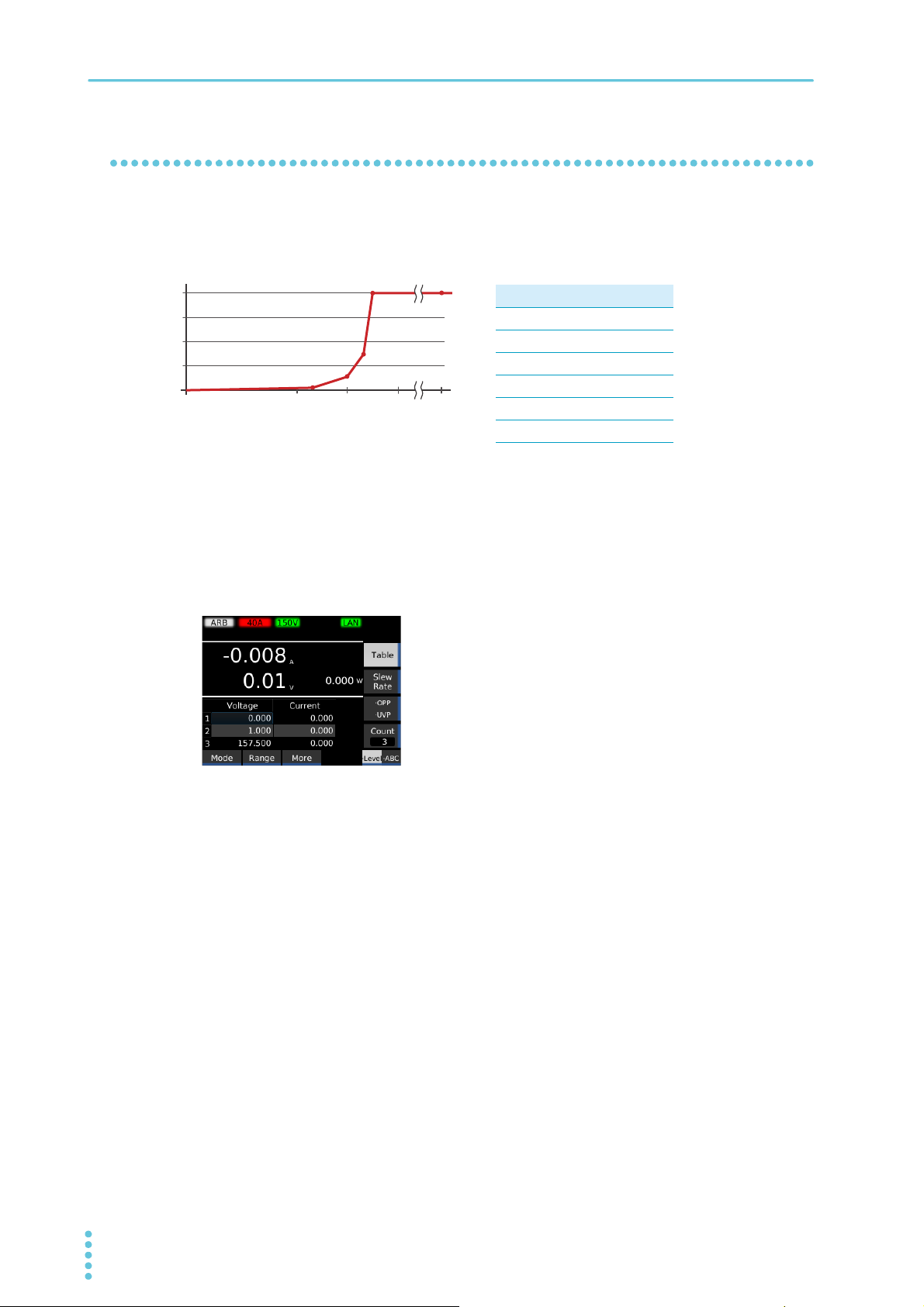
I-V characteristics example
Setting the load value in ARB mode
In ARB mode, arbitrary I-V characteristics can be set by registering multiple I-V characteristic points (set of
voltage value and current value). Three up to 100 points can be registered, and the space between two
points is linearly interpolated. This mode can be used for simulation of LED loads and the like.
Displaying the I-V characteristics editing screen
Example of settings (values with an asterisk are fixed)
Voltage [V] Current [A]
0* 0*
3.2 0.02
4.0 0.1
4.3 0.3
4.5 0.8
157.5* 0.8
Set the operation mode to ARB mode (p.25).
1
Press Level and then Table.
2
The I-V characteristics editing screen appears.
30 User’s Manual PLZ-5W
 Loading...