

Page 1
Part No. Z1-002-802, IB004182
Sep. 2003
OPERATION MANUAL
ELECTRONIC LOAD PLZ-4W Series
PLZ2004 WB
Page 2

al w
Use of Operation Man ual
Please read through and understand this Operation Manual before operating the product. After reading,
ays k eep the manual nearby so that you may refer to it as needed. When mo ving the product to another
location, be sure to bring the manual as well.
If you fi nd an y incorrectly arranged or missing pages in this manual, the y will be replaced. If the manual it
gets lost or soiled, a ne w cop y can be pro vided for a fee. In either case, please contact Kikusui distrib utor/
agent, and pro vide the “Kikusui P art No. ” gi v en on the co v er .
This manual has been prepared with the utmost care; ho we v er , if you ha v e an y questions, or note an y errors
or omissions, please contact Kikusui distrib utor/agent.
Reproduction and reprinting of this operation manual, whole or partially , without our permission is prohib ited.
Both unit specifi cations and manual contents are subject to change without notice.
Cop yright© 2003 Kikusui Electronics Corporation
Printed in Japan
Page 3
P o
Po
•
•
wer Requirements of this Pr oduct
wer requirements of this product ha v e been changed and the rele v ant sections of the Operation
Manual should be re vised accordingly .
(Re vision should be applied to items indicated by a check mark .)
✓
Input v oltage
The input v oltage of this product is
and the voltage range is
to VAC. Use the product within this range only.
VAC ,
Input fuse
The rating of this product's input fuse is A,
WARNING
To avoid electrical shock, always disconnect the power cord or turn off
the switch on the switchboard before attempting to check or replace the
fuse.
• Use a fuse element having a shape, rating, and characteristics suitable
for this product. The use of a fuse with a different rating or one that short
circuits the fuse holder may result in fire, electric shock, or irreparable
damage.
VAC, and .
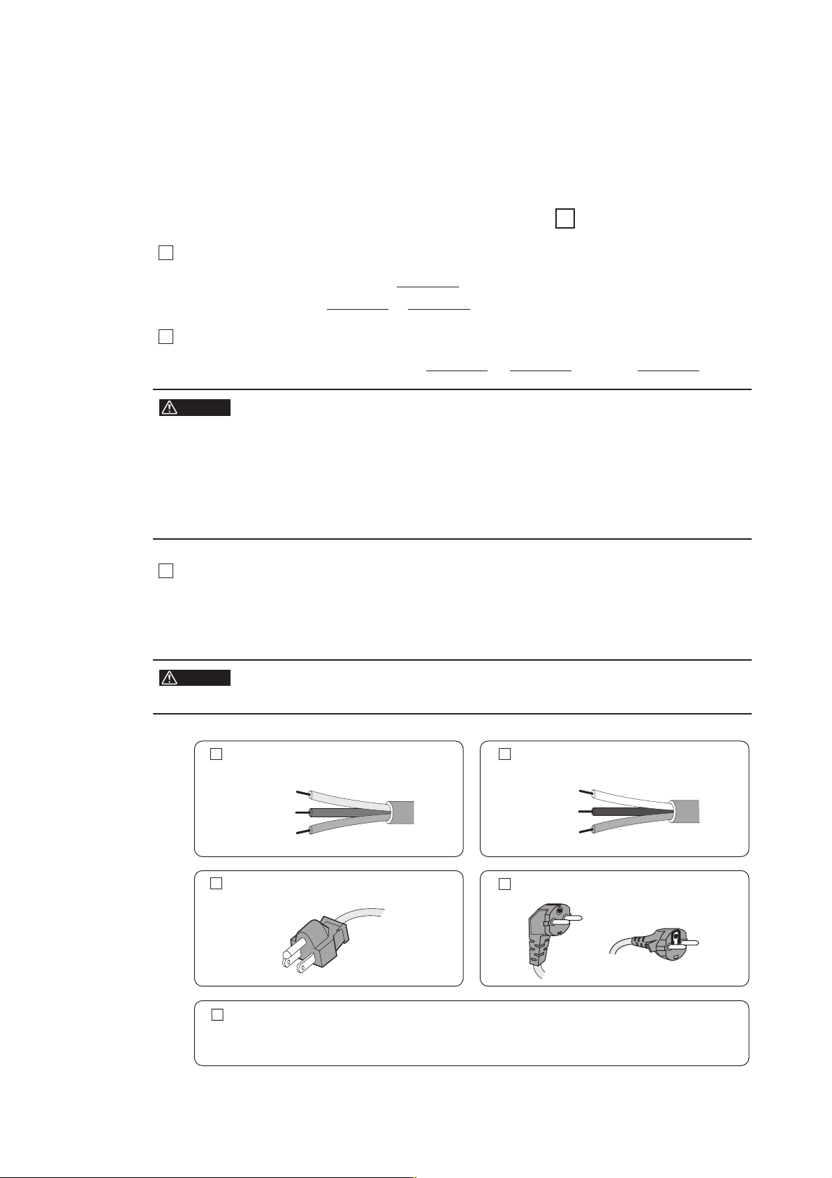
P ower cord
The product is pro vided with power cords described below. If the cord has no power plug,
attach a power plug or crimp-style terminals to the cord in accordance with the wire colors
specified in the drawing.
WARNING
The attachment of a power plug or crimp-style terminals must be carried
out b y qualified personnel.
Without a power plug Without a power plug
Blue (NEUTRAL )
Brown (LIVE)
Green/Yellow (GND)
Plugs for USA
White (NEUTRAL)
Black (LIVE)
Green or Green/Yellow (GND)
Plugs for Europe
Provided by Kikusui distributor/agent
Kikusui agents can provide you with suitable power cord.
For further information, contact Kikusui distributor/agent.
PLZ2004WB
I
Page 4

II
PLZ2004WB
Page 5

Safety Symbols
For the safe use and safe maintenance of this product, the following
symbols are used throughout this manual and on the product. Understand the meanings of the symbols and observe the instructions they
indicate (the choice of symbols used depends on the products).
Indicates that a high v oltage (o v er 1 000 V) is used here . T ouch -
OR
ing the par t causes a possib ly f atal electr ic shoc k. If ph ysical
contact is required b y y our w or k, star t w or k only after y ou mak e
sure that no v oltage is output here .
DANGER
WARNING
CAUTION
Indicates an imminently hazardous situation which, if ignored,
will result in death or ser ious injur y .
Indicates a potentially hazardous situation which, if ignored,
could result in death or ser ious injur y .
Indicates a potentially hazardous situation which, if ignored, ma y
result in damage to the product and other proper ty .
Sho ws that the act indicated is prohibited.
Is placed bef ore the sign “D ANGER, ” “W ARNING, ” or “CA U TION” to emphasiz e these . When this symbol is mar k ed on the
product, see the rele v ant sections in this man ual.
PLZ2004WB
Indicates a protective conductor terminal.
Indicates a chassis (frame) terminal.
Safety Symbols III
Page 6
Safety Precautions
The following safety precautions must be observed to avoid fire hazard,
electrical shock, accidents, and other failures. Keep them in mind and
make sure that all of them are observed properly.
Users
Operation
Manual
Line
Voltage
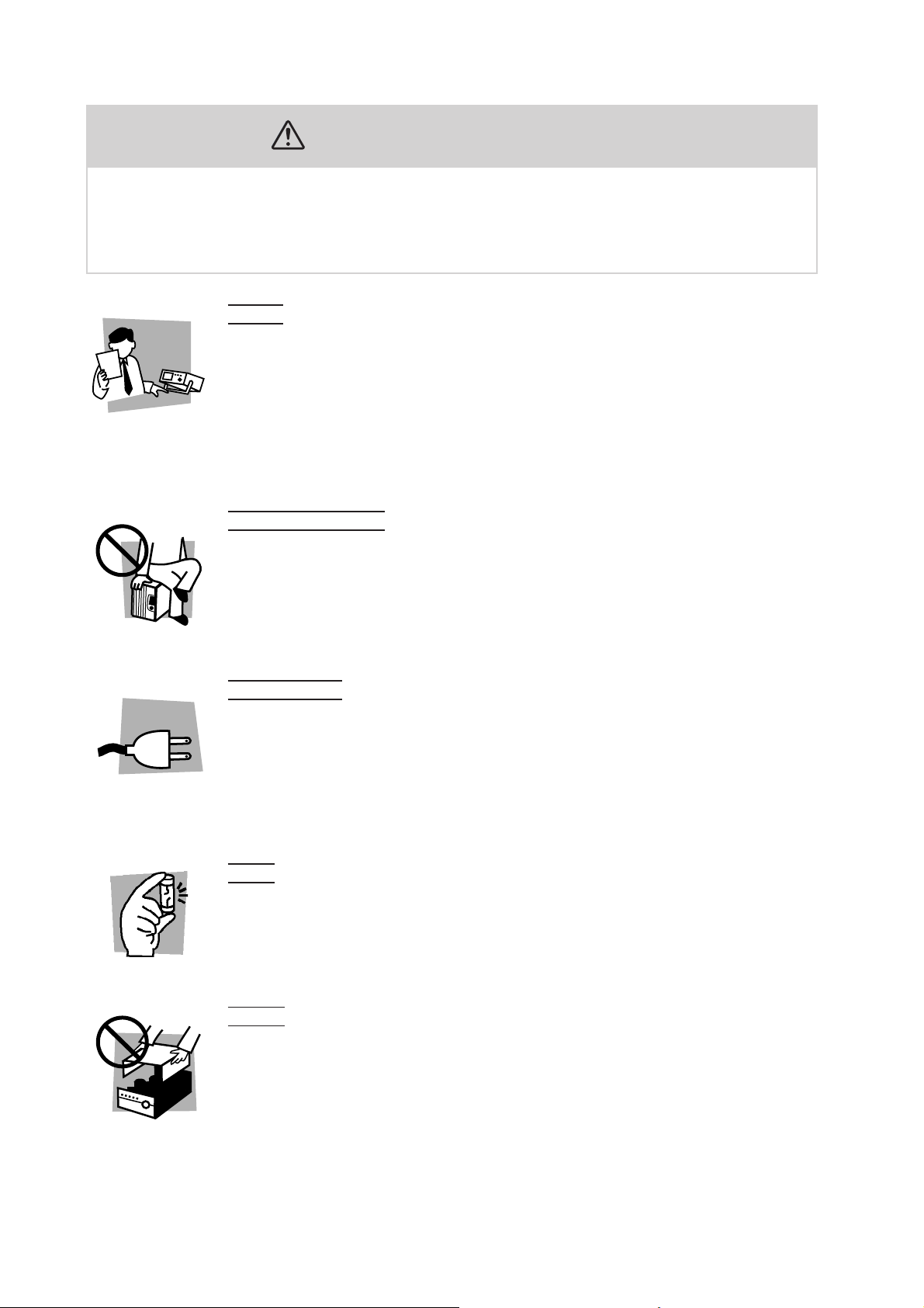
• This product must be used only by qualified personnel who understand the contents of this operation manual.
• If it is handled by disqualified personnel, personal injury may result. Be sure to handle it under supervision of qualified personnel (those who have electrical knowledge.)
• This product is not designed or manufactured for general home or consumer use.
Purposes of use
• Do not use the product for purposes other than those described in the operation
manual.
Input power
• Use the product with the specified input power voltage.
•For applying power, use the power cord provided. Note that the provided power
cord is not use with some products that can switch among different input power
voltages or use 100 V and 200 V without switching between them. In such a case,
use an appropriate power cord.
Fuse
• With products with a fuse holder on the exterior surface, the fuse can be replaced
with a new one. When replacing a fuse, use the one which has appropriate shape,
ratings, and specifications.
Cover
• There are parts inside the product which may cause physical hazards. Do not
remove the external cover.
IV Safety Precautions PLZ2004WB
Page 7
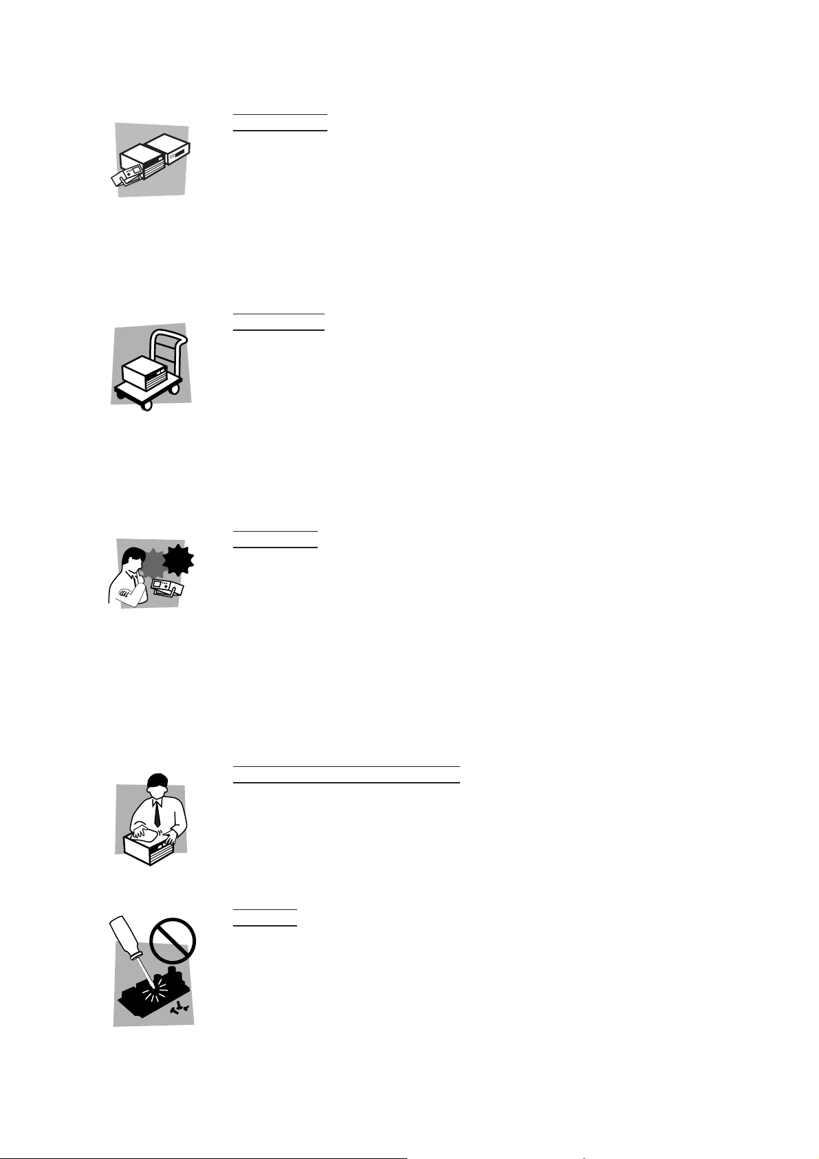
Installation
• When installing products be sure to observe “2.2 Precautions Concerning Installation Location” described in this manual.
•To avoid electrical shock, connect the protective ground terminal to electrical
ground (safety ground).
• When connecting the power cord to a switchboard, be sure work is performed by
a qualified and licensed electrician or is conducted under the direction of such a
person.
• When installing products with casters, be sure to lock the casters.
Relocation
•Turn off the power switch and then disconnect all cables when relocating the
product.
• Use two or more persons when relocating the product which weights more than
20 kg. The weight of the products can be found on the rear panel of the product
and/or in this operation manual.
• Use extra precautions such as using more people when relocating into or out of
present locations including inclines or steps. Also handle carefully when relocating tall products as they can fall over easily.
• Be sure the operation manual be included when the product is relocated.
Check?
Operation
• Check that the AC input voltage setting and the fuse rating are satisfied and that
there is no abnormality on the surface of the power cord. Be sure to unplug the
power cord or stop applying power before checking.
• If any abnormality or failure is detected in the products, stop using it immediately.
Unplug the power cord or disconnect the power cord from the switchboard. Be
careful not to allow the product to be used before it is completely repaired.
•For output wiring or load cables, use connection cables with larger current capacity.
• Do not disassemble or modify the product. If it must be modified, contact Kikusui
distributor/agent.
Maintenance and checking
•To avoid electrical shock, be absolutely sure to unplug the power cord or stop
applying power before performing maintenance or checking.
• Do not remove the cover when performing maintenance or checking.
•To maintain performance and safe operation of the product, it is recommended
that periodic maintenance, checking, cleaning, and calibration be performed.
Service
• Internal service is to be done by Kikusui service engineers. If the product must be
adjusted or repaired, contact Kikusui distributor/agent.
PLZ2004WB Safety Precautions V
Page 8
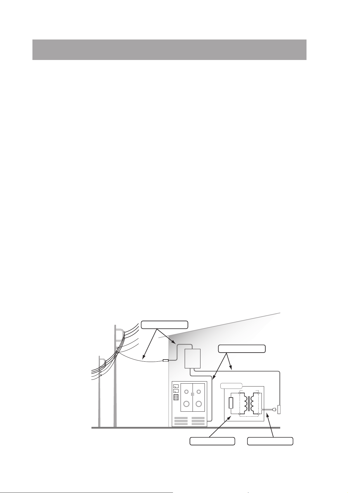
Overvoltage Category
For the safe use of equipment, IEC60664 (Insulation coordination for equipment
within low-voltage systems) classifies circuits into four categories by an occurrence
level of transient voltage. When you connect equipment to a power line or connect a
measuring instrument to these places, make sure of the applied overvoltage category. This instrument is designed to operate from the overvoltage category II.
Overvoltage category I
Equipment of overvoltage category I is equipment for connection to circuits in
which measures are taken to limit transient overvoltages to an appropriately low
level.
Examples are protected electronic circuits.
Overvoltage category II
Equipment of overvoltage category II is energy-consuming equipment to be supplied from the fixed installation.
Examples of such equipment are appliances, portable tools and other household and
similar loads.
If such equipment is subjected to special requirements with regard to reliability and
availability, overvoltage category III applies.
Overvoltage category III
Equipment of overvoltage category III is equipment in fixed installations and for
cases where the reliability and the availability of the equipment is subject to special
requirements.
Examples of such equipment are switches in the fixed installation and equipment for
industrial use with permanent connection to the fixed installation.
Overvoltage category IV
Equipment of overvoltage IV is for use at the origin of the installation.
Example of such equipment are electricity meters and primary overcurrent protection equipment.
Overvoltage category IV
Overvoltage category III
Switch-
Lead-in line
board
Equipment
Powe r transformer
Indoor wiring
Overvoltage category IIOvervoltage category I
Electrical
outlet
VI Overvoltage Category PLZ2004WB
Page 9

Arrangement of this Manual
This Operation Manual is made up of the following sections.
Chapter 1 General Information
This chapter gives an overview and describes the features of the PLZ2004WB.
Chapter 2 Installation and Preparation
This chapter describes the procedures of unpacking and preparation of the
PLZ2004WB before use.
Chapter 3 Names and Functions of Parts
This chapter describes the names and functions of switches, displays, connectors,
and other parts of the front panel and rear panel.
Chapter 4 Maintenance
This chapter describes maintenance and calibration of the PLZ2004WB.
Chapter 5 Specifications
This chapter describes the electrical and mechanical specifications of the
PLZ2004WB.
PLZ2004WB Arrangement of this manual VII
Page 10

Contents
Power Requirements of this Product __________________________ I
Safety Symbols ___________________________________________ III
Safety Precautions _______________________________________ IV
Overvoltage Category _____________________________________ VI
Arrangement of this Manual _______________________________ VII
Chapter 1 General Information 1-1
Chapter 2 Installation and Preparation 2-1
2.1 Checking the Package Contents - - - - - - - - - - - - - - - - - - - - - - - - - - - - - 2-1
2.2 Precautions Concerning Installation Location - - - - - - - - - - - - - - - - - - - - 2-2
2.3 Precautions When Moving the Unit - - - - - - - - - - - - - - - - - - - - - - - - - - 2-3
2.4 Connecting the Power Cord - - - - - - - - - - - - - - - - - - - - - - - - - - - - - - - - 2-4
2.5 Grounding - - - - - - - - - - - - - - - - - - - - - - - - - - - - - - - - - - - - - - - - - - - 2-5
2.6 Parallel Connection - - - - - - - - - - - - - - - - - - - - - - - - - - - - - - - - - - - - - 2-6
2.6.1 Connecting the Signal Cables - - - - - - - - - - - - - - - - - - - - - - - - 2-7
2.6.2 Load Wiring - - - - - - - - - - - - - - - - - - - - - - - - - - - - - - - - - - - - 2-7
2.7 Setting the Master Unit - - - - - - - - - - - - - - - - - - - - - - - - - - - - - - - - - - 2-10
Chapter 3 Names and Functions of Parts 3-1
3.1 Front Panel - - - - - - - - - - - - - - - - - - - - - - - - - - - - - - - - - - - - - - - - - - - 3-1
3.2 Rear Panel - - - - - - - - - - - - - - - - - - - - - - - - - - - - - - - - - - - - - - - - - - - 3-2
Chapter 4 Maintenance 4-1
4.1 Cleaning - - - - - - - - - - - - - - - - - - - - - - - - - - - - - - - - - - - - - - - - - - - - - 4-1
4.1.1 Cleaning the Panels - - - - - - - - - - - - - - - - - - - - - - - - - - - - - - - 4-1
4.1.2 Cleaning the Dust Filter - - - - - - - - - - - - - - - - - - - - - - - - - - - - 4-1
4.2 Inspection - - - - - - - - - - - - - - - - - - - - - - - - - - - - - - - - - - - - - - - - - - - - 4-3
4.3 Calibration - - - - - - - - - - - - - - - - - - - - - - - - - - - - - - - - - - - - - - - - - - - 4-3
Chapter 5 Specifications 5-1
5.1 Electrical Specifications - - - - - - - - - - - - - - - - - - - - - - - - - - - - - - - - - - 5-1
5.2 General Specifications - - - - - - - - - - - - - - - - - - - - - - - - - - - - - - - - - - - 5-3
5.3 Dimensions - - - - - - - - - - - - - - - - - - - - - - - - - - - - - - - - - - - - - - - - - - - 5-4
Index I- 1
VIII Contents PLZ2004W
Page 11

Chapter 1 General Information
This chapter gives an overview and describes the features of the PLZ2004WB.
About This Manual
This operation manual describes the PLZ2004WB Load Booster.
The PLZ2004WB is used in combination with the PLZ1004W Electronic Load.
This manual mainly covers the handling precautions of the PLZ2004WB and the
connection to the PLZ1004W. For the operating procedure as a electronic load, see
the PLZ1004W Operation Manual.
Product Overview
The PLZ2004WB Load Booster is used to increase the input current to the
PLZ1004W Electronic Load. One PLZ1004W is made the master unit, and load
boosters connected in parallel operate as slave units.
Features
Options
• Up to four load boosters can be connected in parallel with a PLZ1004W master
unit, configuring a electronic load that produces up to 9 kW and 1 800 A.
• The master unit displays the total current and total wattage. The units connected
in parallel can be used as a single electronic load.
• The connection of the control cables is easy. The control cable used to connect
between the master unit and the load booster and between each load booster is
one flat cable each.
• There is no power switch. The AC input power is turned ON/OFF by the master
unit.
Control flat cables
Control cable used to connect between the master unit and the load booster and
between load boosters. The following two types of cables are available.
Model Code Length Application
PC01-PLZ-4W 84540 300 mm Connect between load boosters
PC02-PLZ-4W 84550 550 mm Connect between the master unit and load booster
The two types of cables only differ in their length. The 550-mm PC02-PLZ-4W is
required to connect the master unit and the load booster.
PLZ2004WB General Information 1-1
Page 12

Rack mount bracket
The following rack mounting brackets are available.
• KRB3-TOS (for inch-rack EIA standard)
• KRB150-TOS (for milli rack JIS standard)
For details, contact Kikusui distributor/agent.
KRB3-TOS
(465)
479
5737.5
132
KRB150-TOS
(460)
479
Fig.1-1 Rack mount bracket installation example
100
24.5
149
Unit: mm
1-2 General Information PLZ2004WB
Page 13

Chapter 2 Installation and Preparation
This chapter describes the procedures of unpacking and preparation of the
PLZ2004WB before use.
2.1 Checking the Package Contents
When you receive the product, check that all accessories are included and that the
product and accessories have not been damaged during transportation.
If any of the accessories are damaged or missing, contact Kikusui distributor/agent.
NOTE
• It is recommended that all packing materials be saved, in case the product needs
to be transported at a later date.
The power cord that is
Or
[85-AA-0003] [85-AA-0005]
Power cord
(1 pc.)
[Q1-500-096]
[Q1-900-020]
Load input terminal cover (2 pcs.)
[with auxiliary band]
[M4-000-131]
Set of screws for the load input terminal
(2 sets)
provided varies depending on
the destination for the product
at the factory-shipment.
[M1-000-121]
[M5-001-101]
OPERATION MA
ELECTRONIC LOAD PLZ-4W Ser
P
art
N
o
.
PL
Z2004
Operation manual (1 copy)
Z1-002-802
A
,
IB
u
00
g.
4
1
200
NUAL
81
3
WB
ies
[Z1-002-802]
[84-49-0071]
J2 protection dummy plug (1 pc.)
[Attached to the J2 connector on the rear panel.]
Fig.2-1 Accessories
PLZ2004WB Installation and Preparation 2-1
Page 14

2.2 Precautions Concerning Installation Location
This section describes the precautions to be taken when installing the unit. Make
sure to observe them.
■ Do not use the unit in a flammable atmosphere.
To prevent the possibility of explosion or fire, do not use the unit near alcohol, thinner or other combustible materials, or in an atmosphere containing such vapors.
■ Avoid locations where the unit is exposed to high temperature
or direct sunlight.
Do not place the unit near a heater or in areas subject to drastic temperature
changes.
Operating temperature range: 0 °C to 40 °C
Storage temperature range: -25 °C to +70 °C
■ Avoid humid environments.
Do not place the unit in high-humidity locations--near a boiler, humidifier, or water
supply.
Operating humidity range: 20 % to 85 % RH (no condensation)
Storage humidity range: 0 % to 90 % RH (no condensation)
Condensation may occur even within the operating humidity range. In such case, do
not use the unit until the condensation dries up completely.
■ Do not place the unit in a corrosive atmosphere.
Do not install the unit in a corrosive atmosphere or in environments containing sulfuric acid mist, etc. This may cause corrosion of various conductors and bad contacts of connectors inside the unit leading to malfunction and failure, or in the worst
case, a fire.
However, operation in such environments may be possible through alteration. If you
wish to use the unit in such environments, consult Kikusui distributor/agent.
■ Do not place the unit in a dusty location.
Accumulation of dust can lead to electric shock or fire.
■ Do not use the unit where ventilation is poor.
The unit employs a forced air cooling system. Air is taken in from intake ports
located on panels other than the rear panel and exhausted from the ports on the rear
panel. Secure adequate space around the unit to prevent the possibility of fire caused
by accumulation of heat.
■ Do not place the unit on an inclined surface or location subject to vibrations.
The unit may fall or tip over causing damages and injuries.
2-2 Installation and Preparation PLZ2004WB
Page 15

■ Do not use the unit in a location subject to strong magnetic or
electric fields.
The unit may malfunction and cause electric shock or fire.
■ Do not use the unit near highly sensitive measuring instru-
ments or transceivers.
The noise generated by the unit may affect them
■ Do not stack more than two units on top of each other.
The units (load booster and master unit) can be stacked, but do not stack more than
two units on top of each other for safety reasons.
If you are using multiple load boosters, it is recommended that they be mounted on
a rack.
DC INPUT
DC INPUT
1000W
1.5-150V
0-66A
I MON
PLZ2004WB
TRIG
ELECTRONIC LOAD
POWER
REMOTE
OUTOUT
2000W
-
150V
1.5
-
0
400A
POWER
Fig. 2-2 Stacking of the electronic loads
1000W
-
1.5
150V
-
66A
0
I MON
OUT
PLZ2004WB
ELECTRONIC LOAD
Do not stack
more than
2000W
-
150V
1.5
-
0
400A
POWER
two units.
2.3 Precautions When Moving the Unit
When moving the unit to the installation location or when transporting the unit, note
the following points.
■ Remove all wiring.
Moving the unit with the cables connected can cause wires to break or injuries due
to the unit falling over.
■ Have two or more people move the unit.
The unit weighs over 20 kg. Have two or more people move the unit. Use extra precaution at inclines and steps.
■ When transporting the unit, be sure to use the original pack-
ing materials.
Otherwise, damage may result from vibrations or from the unit falling during transportation.
PLZ2004WB Installation and Preparation 2-3
Page 16

2.4 Connecting the Power Cord
The power cord that is provided varies depending on the destination for the product
at the factory-shipment.
WARNING
• This product is designed to be connected to a power supply classified as
Overvoltage Category II. Do not connect to a power supply classified as
Overvoltage Category III or IV. For a description of the Overvoltage Category, see “Overvoltage Category” on page VI.
• The power cord for 100-V system shown in Fig. 2-3 has a rated voltage of
125 VAC. If this power cord is used at the line voltage of a 200-V system,
replace the power cord with that satisfying that line voltage.
Have a qualified engineer select the appropriate power cord. If obtaining
the right power cord is difficult, contact Kikusui distributor/agent.
• Do not use the power cord that comes with the product as a power
cord for other equipment.
Power cord for 100-V system
[85-AA-0003]
Rated voltage: 125 VAC
Rated current: 10 A
Power cord for 200-V system
[85-AA-0005]
Rated voltage: 250 VAC
Rated current: 10 A
Fig. 2-3 Power cord with a three-pin plug
Follow the procedures below to connect the power cord.
NOTE
• The load booster does not have a power switch. The AC input power is turned on/
off in sync with the master unit when the load booster is connected to the master
unit through the control cable.
1. Check that the AC power supply is within the input power supply range
of the product.
The allowable voltage range and frequency range of the AC input power are 90
VA C to 250 VAC and 47 Hz to 63 Hz, respectively.
2.
Connect the power cord to the AC INPUT connector on the rear panel.
Use a power cord specified by Kikusui or one that has been selected by a qualified engineer.
3.
Insert the power plug to the outlet.
2-4 Installation and Preparation PLZ2004WB
Page 17

2.5 Grounding
WARNING
CAUTION
• Electric shock may occur, if proper grounding is not furnished.
• This product is designed as a Class I equipment (equipment furnished
with electric shock protection through protective grounding in addition to
the basic insulation). Be sure to connect the protective ground terminal to
an appropriate earth ground.
• If you do not ground the product, malfunction may occur due to external
noise, or the noise generated by the product may become large.
Make sure to ground the load booster for your safety.
Connect the power cord to a three-prong power outlet with proper grounding.
Three-prong outlet with
proper grounding
Fig. 2-4 Grounding method
PLZ2004WB Installation and Preparation 2-5
Page 18

2.6 Parallel Connection
To carry out parallel operation, you must connect signal wires used to connect to the
master unit and the load cable used to connect to the equipment under test.
Use the optional flat cable for the signal wire. For details, see “Control flat cables”
in chapter 1, “General Information.”
Up to four load boosters can be connected. Here, an example in which two load
boosters are connected is indicated.
WARNING
Flat cable
PC02-PLZ-4W
(Option)
Flat cable
PC01-PLZ-4W
(Option)
• There is a danger of electric shock. Do not touch the load connector while
the power is on.
Master unit
Load booster 1
Load booster 2
+
Equipment
under test
–
Load wire
J1
J2
J1
J2
+
–
J1
J2
J1
J2
J1
J2
DC INPUT
1000W
-
1.5
150V
-
200A
0
DC INPUT
2000W
1.5
0
DC INPUT
2000W
1.5
0
+
-
150V
-
400A
+
-
150V
-
400A
–
–
Fig. 2-5 Parallel connection of two load boosters
Table 2-1shows the relationship between the number of load boosters and the capacity.
Ta ble2-1 The number of load boosters connected in parallel and
the capacity
Number of load boosters (n)
1 600 A / 3 000 W
21 000 A / 5 000 W
31 400 A / 7 000 W
41 800 A / 9 000 W
2-6 Installation and Preparation PLZ2004WB
Maximum current/maximum power
PLZ1004W + (PLZ2004WB × n)
Page 19

CAUTION
• Be sure to use the load input terminals on the rear panel on the master
unit. Do not connect other equipment to the load input terminal on the front
panel.
• Improper connection of the J1 and J2 connectors can damage the
PLZ2004WB.
•Take into account the current used, and make the load cable as short as
possible with sufficient thickness.
NOTE
• Separate the load cable from the flat cable as much as possible to prevent unstable
operation.
2.6.1 Connecting the Signal Cables
Use the optional cable for the connection cable.
Tu rn off the POWER switch on the master unit.
1.
Unplug the power cord plug of the load booster.
2.
Connect between J2 of the master unit and J1 of load booster 1 using
3.
the optional flat cable (PC02-PLZ-4W).
4. Connect between J2 of load booster 1 and J1 of load booster 2 using
the optional flat cable (PC01-PLZ-4W).
When connecting more load boosters, make similar connections.
2.6.2 Load Wiring
NOTE
• Precautions and items to be considered during load wiring when using the master
unit alone also apply to parallel operation.
Before wiring the load for parallel operation, read section 2.8, “Load Wiring” in
the PLZ1004W Operation Manual to familiarize yourself with the precautions and
items to be considered.
Electric wire used
CAUTION
PLZ2004WB Installation and Preparation 2-7
• Use a load wire with sufficient diameter for the current as well as non-flam-
mable or flame-resistant cover.
A table indicating “nominal cross-sectional area of wires and allowable currents” is
given in section 2.8, “Load Wiring” in the PLZ1004W Operation Manual. Refer to
this table and select the thickest wire possible.
Page 20

Connection to the load input terminal
The load input terminal on the PLZ1004W (master unit) is not designed for large
currents as in the load input terminal of the load booster.
As shown in Fig. 2-5, separate the load wire from the equipment under test for the
master unit and the load booster.
WARNING
CAUTION
• There is a danger of electric shock. Do not touch the load input terminal
while the power is on.
In addition, be sure to use the load input terminal cover.
• There is a danger of overcharge. Attach crimping terminal to the wire and
use the set of screws that came with the package for connection.
1. Tu rn off the POWER switch on the master unit.
Unplug the power cord plug of the load booster.
2.
Check that the output of the equipment under test is off.
3.
Connect the load wire to the load input terminal of the master unit.
4.
For the connection procedure of the load wire, see section 2.8, “Load Wiring”
in the PLZ1004W Operation Manual.
5.
As shown in Fig. 2-6, connect the load wire to the load input terminal of
the load booster.
Use the load input terminal cover. See Fig. 2-7 on how to use the cover.
6.
Connect the master unit, load booster, and the equipment under test.
Check the polarity of the connections.
7.
Be sure to use the set
of screws provided
with the package.
Fig. 2-6 Connection to the load input terminal
Bolt (M12 × 25)
Spring washer (M12)
Crimp terminal
Nut (M12)
2-8 Installation and Preparation PLZ2004WB
Page 21

Wrap the auxiliary band between the rear panel and the
bolt.
1
Auxiliary band
The auxiliary band prevents the load input
terminal cover from sliding. Wrap the band
tightly to fill up the space between the panel
and the bolt.
Load input terminal cover
Wrap the load input terminal cover
over the auxiliary band.
2
Wrap the cover leaving as little
space as possible here.
Fig. 2-7 Attachment of the load input terminal cover
PLZ2004WB Installation and Preparation 2-9
Page 22

2.7 Setting the Master Unit
1. Tu rn on the power to the master unit.
The power to the load booster is in sync with the power to the master unit.
2.
Select the menu setup.
Press the MENU (SHIFT+SET/VSET) key.
The menu appears.
3.
Select Configuration
Press the or CURSOR key several times until Configuration is high-
lighted. When highlighted, press the ENTER key.
4.
Select Master/Slave
Press the or CURSOR key several times until Master/Slave is highlighted. When highlighted, press the ENTER key.
5.
Set the master unit.
Check to see that the cursor (blinking) is at the Operation item. If the cursor is
at some other item, press the CURSOR key several times to move the cursor
to Operation.
6.
Master/Slave
Operation:MASTER
Parallel:-Booster:--
PREV
Set as a master unit.
First, turn the rotary knob to the right to select MASTER.
Press the CURSOR key twice to move the cursor (blinking) to the Booster
item.
Turn the rotary knob to set the number of load boosters.
7.
Exit from the menu.
Press the MENU (SHIFT+SET/VSET) key.
On the master unit, the original screen displayed before entering menu
setup appears.
8.
Power cycle the master unit.
The menu settings are confirmed.
9.
Set the operation mode and value, and turn on the load.
Operate the master unit to set the master mode and value of the parallel connection. The range of the rated current and rated power on the master unit is
expanded.
After entering the settings, turn off the load.
2-10 Installation and Preparation PLZ2004WB
Page 23

Chapter 3 Names and Functions of Parts
This chapter describes the names and functions of switches, displays, connectors,
and other parts of the front panel and rear panel.
3.1 Front Panel
2
ELECTRONIC LOAD
PLZ2004WB
2000W
1.5
-
0
-
400A
150V
Fig.3-1 PLZ2004WB Front Panel
[1] POWER lamp
Illuminates when the power switch of the master unit is on when the load booster is
connected in parallel with the master unit. It indicates that AC input power is being
supplied.
The PLZ2004WB does not have a power switch. The AC input power is turned ON/
OFF by the master unit.
[2] Air intake (louver)
Inlet port used to exhaust the internal heat using a fan.
A dust filter is furnished on the inside. Clean the dust filter periodically. For details,
see section 4.1.2, “Cleaning the Dust Filter.”
POWER
1
PLZ2004WB Names and Functions of Parts 3-1
Page 24

3.2 Rear Panel
3
WARNI NG
TO AVOID ELECTRIC SHOCK, THE POWER CORD
PROTECTIVE GROUNDING CONDUCTOR MUST
BE CONNECTED TO GROUND.
DO NOT REMOVE COVERS, REFER
SERVICING TO QUALIF IED PERSONNEL.
AC INPUT
100-240V
-
63Hz
47
200VA MAX
5
4
6
Fig. 3-2 PLZ2004WB Rear panel
[3] J1 and J2 connectors
Connector used to connect the control signal using the optional flat cable.
[4] DC INPUT (Load input terminal)
Input connector used to connect to the equipment under test.
[5] AC INPUT connector
AC power input connector.
WARNING
•Possible electric shock. May lead to death or injury. Be sure to follow the
directions given in section 2.4, “Connecting the Power Cord.”
[6] Air outlet
Air outlet used to exhaust the internal heat using a fan. Provide adequate space
around the PLZ2004WB to allow sufficient air circulation.
3-2 Names and Functions of Parts PLZ2004WB
Page 25

Chapter 4 Maintenance
This chapter describes maintenance and calibration of the PLZ2004WB.
WARNING
•Possible electric shock. May lead to death or injury. Do not remove the
external cover.
4.1 Cleaning
WARNING
4.1.1 Cleaning the Panels
CAUTION
•Possible electric shock. May lead to death or injury. Be sure to unplug the
power cord plug.
If the panel needs cleaning, gently wipe using a soft cloth with water-diluted neutral
detergent.
• Do not use volatile solvents such as thinner or benzine. They may discolor
the surface or erase the printed characters.
4.1.2 Cleaning the Dust Filter
A dust filter is installed on the inside of the louver on the front panel. Periodically
clean the filter to prevent clogging.
CAUTION
• Clogged filters hinder the cooling of the inside of the instrument and can
cause a malfunction and shortening of the service life.
PLZ2004WB Maintenance 4-1
Page 26

Cleaning procedure
1. Remove the louver from the panel by placing a finger on the 2nd level of
the louver and pulling down the 1st level while pulling it toward you.
If the louver does not come off easily, pressing down the top level of the louver
will ease the work.
Fig.4-1 Removing the louver
2.
Remove the dust filter from the inside of
the louver and clean it.
Remove the dust on the dust filter such as
by using a vacuum cleaner. If the filter is
extremely dirty, clean it using a waterdiluted neutral detergent and dry it completely.
2nd level
1st level
Louver
Dust filter
Tab
Cut
CAUTION
Fig. 4-2 Dust filter
• When the PLZ2004WB is in operation, air is sucked through the dust filter
to cool the load booster. If moister is included in the dust filter, the temperature or humidity inside the PLZ2004WB increases and may cause a malfunction.
Attach the dust filter to the louver.
3.
Attach it so that the tab on the louver fits into the cut on the dust filter.
4.
Attach the louver to the panel by pulling up on the louver while holding the
2nd level of the louver with your hand
until the pin is fixed in place.
Pin
Fig. 4-3 Attaching the louver
4-2 Maintenance PLZ2004WB
Page 27

4.2 Inspection
Power cord
Check that the insulation coating is not broken and that the crimp terminal is not
loose.
WARNING
•Possible electric shock. May lead to death or injury. Be sure to unplug the
power cord plug.
• Breaks in the insulation coating may cause electric shock. If a break is
found, stop using it immediately.
To purchase accessories, contact Kikusui distributor/agent.
4.3 Calibration
The PLZ2004WB is shipped from the factory after carrying out a strict calibration.
However, to maintain the performance, periodic calibration is recommended.
Calibration can be performed in the same fashion as the calibration of the master
unit alone by viewing the load device connected in parallel (master unit and load
boosters) as a single load device. For details, see section 8.2, “Calibration” in the
PLZ1004W Operation Manual.
Use shunt resistors and regulated DC power supplies of appropriate current capacity
in the calibration.
PLZ2004WB Maintenance 4-3
Page 28

4-4 Maintenance PLZ2004WB
Page 29

Chapter 5 Specifications
This chapter describes the electrical and mechanical specifications of the
PLZ2004WB.
5.1 Electrical Specifications
Unless specified otherwise, the specifications are for the following settings and conditions.
•Warm-up period: 30 minutes (with current flowing)
• Ambient temperature: 23 °C ± 5 °C
• ** % of set denotes ** % of the input voltage, input current, or input power set-
ting.
• ** % of f.s denotes ** % of the rated input voltage, rated input current, or rated
input power.
Rating
Operating voltage (DC) 1.5 V to 150 V
Current 400 A
Power 2 000 W
Minimum operating start voltage
Current setting accuracy
*1
Minimum voltage at which the current starts flowing to the PLZ2004WB.
*2
Condition in which the PLZ2004WB is connected to the master unit but not calibrated.
*3
Full scale of H range.
Protection function
Overheat protection (OHP)
Reverse connection protection (REV) Protection by fuse.
*2
*1
Range
0.3 V or greater
H and M
L ±(1.2 % of set + 1.1 % of f.s)
±(1.2 % of set + 1.1 % of f.s*3)
Turns off the load when the heat sink temperature
reaches 95 °C.
PLZ2004WB Specifications 5-1
Page 30

Input/output signal
J1 connector 20-pin MIL connector
Used to connect to the master unit
(or load booster)
1NC 1NC
2 NC 2 NC
3 NC 3 NC
4 SUM I MON Connect to SUM I MON of the J2
connector.
5 PRL IN+ Connect to PRL OUT+ of the J2 con-
nector.
6 PRL IN- Connect to PRL OUT- of the J2 con-
nector.
7NC 7 NC
8NC 8NC
9 RANGE
CONT 0
10 NC 10 NC
11 NC 11 NC
12 A COM Connect to the negative load input
13 NC 13 NC
14 NC 14 NC
15 NC 15 NC
16 ALARM
OUTPUT
17 A COM Connect to the negative load input
18 NC 18 NC
19 A COM Connect to the negative load input
20 +15V For controlling the on/off of the load
Connect to SLAVE RANGE CONT
of the J2 connector.
terminal.
Activates an alarm with high (or low)
TTL level signal input.
terminal.
terminal.
booster power (multi-purpose use
not allowed)
J2 connector 20-pin MIL connector
4 SUM I MON Connect to SUM I MON of the J1
5 PRL OUT+ Connect to PRL IN+ of the J1 con-
6 PRL OUT- Connect to PRL IN- of the J1 con-
9 SLAVE RANGE
CONT
12 A COM Connect to the negative load input
16 ALARM
INPUT
17 A COM Connect to the negative load input
19 A COM Connect to the negative load input
20 +15V For controlling the on/off of the load
Used to connect to load booster n
connector.
nector.
nector.
Connect to RANGE CONT 0 of the
J1 connector.
terminal.
Activates an alarm with high (or low)
TTL level signal input.
terminal.
terminal.
booster power (multi-purpose use
not allowed)
5-2 Specifications PLZ2004WB
Page 31

5.2 General Specifications
Environment
Input line voltage range 100 VAC to 240 VAC (90 VAC to 250 V) single phase, continuous
Input frequency range 47 Hz to 63 Hz
Power consumption 200 VAmax
Inrush current 35 A
Insulation
resistance
Withstand
voltage
Dimensions (mm) See outline drawing.
Weight Approx. 24 kg
Accessories Power cord 1 pc. (with SVT3, 18AWG, 3-prong plug, cable length of 2.4 m)
Electromagnetic compatibility
*1
(EMC)
*1,*2
Safety
Operating temperature and
humidity range
Storage temperature and
humidity range
Primary - input connector 500 VDC, 30 MΩ or more (ambient humidity of 70% RH or less)
Primary - chassis 500 VDC, 30 MΩ or more (ambient humidity of 70% RH or less)
Input connector - chassis 500 VDC, 30 MΩ or more (ambient humidity of 70% RH or less)
Primary - input connector No abnormalities at 1 500 VAC for 1 minute.
Primary - chassis No abnormalities at 1 500 VAC for 1 minute.
Load input terminal cover 2 sets (cover and auxiliary band)
Screw set for th load input
terminal
Operation manual 1 pc.
J2 protection dummy flag 1 pc.
Temperature: 0 °C to 40 °C
Humidity: 20% to 85% RH (no condensation)
Temperature: -25 °C to 70 °C
Humidity: Less than or equal to 90% (no condensation)
2 sets (bolts, nuts, and spring washers)
Conforms to the requirements of the following directive and
standard.
EMC Directive 89/336/EEC
EN61326:1997/A2:2001
Emissions: Class A
Immunity: Minimum immunity test requirements
EN61000-3-2:2000
EN61000-3-3:1995/A1:2001
Conforms to the requirements of the following directive and
standard.
Low Voltage Directive 73/23/EEC
EN61010-1:2001
Class I
Pollution degree 2
*1
Only on models that have CE marking on the panel.
Not applicable to custom order models.
*2
This instrument is a Class I equipment. Be sure to ground the protective conductor terminal of the instrument. The safety of the instrument is not guaranteed unless the instrument is grounded properly
PLZ2004WB Specifications 5-3
Page 32

5.3 Dimensions
MAX440
429.5
128
MAX150
Fig.5-1 PLZ2004WB outline drawing
MAX600
550
Unit: mm
5-4 Specifications PLZ2004WB
Page 33

Inde x
A
AC INPUT connector 3- 2
accessories 2- 1
air intake 3- 1
air outlet 3- 2
C
calibration 4- 3
Class I equipment 2- 5
cleaning 4- 1
control flat cables 1- 1
D
DC INPUT 3- 2
dust filter 4- 1
E
earth ground 2- 5
O
overvoltage category- VI
Overvoltage Category II 2- 4
P
POWER lamp 3- 1
R
rack mount bracket 1- 2
T
transportation 2- 3
G
grounding 2- 5
I
inspection 4- 3
installation 2- 2
J
J1 connector 3- 2
J2 connector 3- 2
L
load input terminal 3- 2
louver 3- 1
M
moving the unit 2- 3
PLZ2004WB Index I-1
Page 34

I-2 Index
PLZ2004WB
Page 35

Page 36

ELECTRONIC LOAD PLZ2004WB
OPERATION MANUAL
 Loading...