

PART NO. Z1-004-970, IB021883
Oct. 2015
УефхрЗхйде
ELECRONIC LOAD PLZ-4WH Series
PLZ164WH
PLZ334WH
PLZ1004WH
The PLZ-4WH Series Electronic Load is a multifunctional system
designed to offer the highest levels of reliability and safety. The
electronic load contains a stable and high-performance current-control circuit that enables high-speed load simulations. In addition, its
CPU control feature works to improve operability and multifunctional
capability. The high-precision current settings provide you with suf-
cient resolution. Because the electronic load comes standard with
GPIB, RS232C, and USB communication functions, it can be easily
incorporated into a wide range of test and inspection systems.
Checking the Package Contents
When you receive the product, check that all accessories are included and that the product and accessories have not been damaged during transportation. If any of the accessories are damaged
or missing, contact your Kikusui agent or distributor. We recommend
that all packing materials be saved, in case the product needs to be
transported at a later date.
Accessories
About the Manuals
The manuals for the PLZ-4WH Series include the Setup Guide (this
guide), the Quick Reference, the User’s Manual, and the Communication Interface Manual.
The manuals are intended for users of the PLZ-4WH Series Electronic Load and their instructors. Explanations are given under the
presumption that the reader has knowledge of electronics and electronic loads.
Setup Guide (This guide)
•
This guide is intended for rst-time users of the product. It gives
an overview of the product, connecting procedures, safety precautions, etc. Please read through and understand this guide before
operating the product.
Quick Reference
•
The quick reference briey explains the panel description and the
basic operation of the product.
User’s Manual (PDF)
•
This manual provides an overview of the product, notes on usage,
and specications and explains how to connect the product, congure the product, operate the product, perform maintenance on
the product, and so on.
Communication Interface Manual (HTML, PDF)
•
This manual explains the remote control feature.
Interface manual is written for readers with sufcient basic knowl-
edge of how to control instruments using a personal computer.
PDF and HTML files are included in the accompanying CDROM.
Adobe Reader 9.2 or later is required to view the PDF les. Microsoft Internet Explorer 9 or later is required to view the HTML les.
This manual has been prepared with the utmost care; however, if
you have any questions, or note any errors or omissions, please
contact Kikusui distributor/agent.
If you nd any incorrectly arranged or missing pages in manual, they
will be replaced. If the manual gets lost or soiled, a new copy can be
provided for a fee. In either case, please contact Kikusui distributor/
agent, and provide the “Kikusui Part No.” given on the cover.
After reading, always keep the manual nearby so that you may refer
to it as needed.
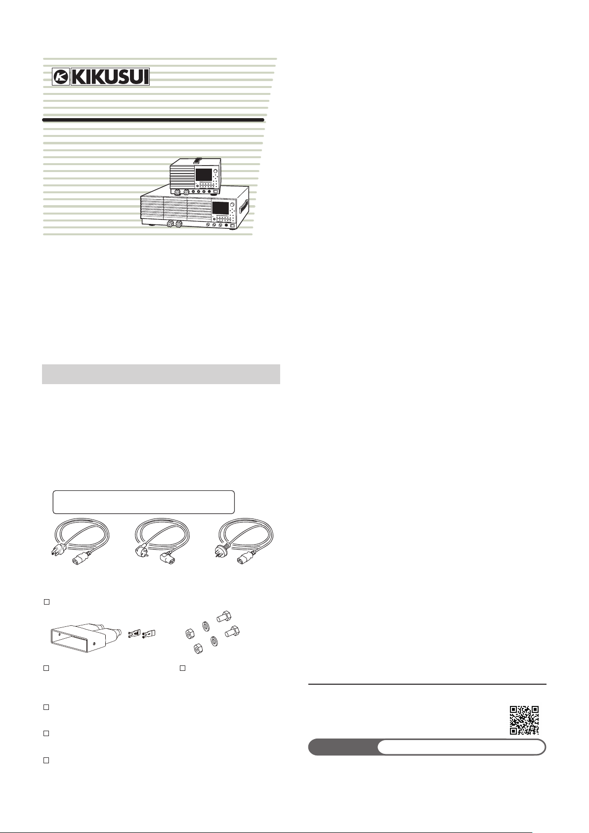
The power cord that is provided varies depending on the
destination for the product at the factory-shipment.
or or
Plug: NEMA5-15
Rating: 125 Vac/10 A
[85-AA-0004]
Power cord (1 pc.)
[Q1-500-085]
Load input terminal cover (1 pc.)
Load input terminal cover screws
(2 pc.)
Quick Reference
(Japanese 1sheet, English 1sheet)
Setup Guide
(This guide; 1 pc.)
CD-ROM (1 pc.)
Plug: CEE7/7
Rating: 250Vac/10 A
[85-AA-0005]
[P2-000-228]
[M4-100-007]
Set of screws for the load
input terminal (2 pairs)
Plug: GB1002
Rating: 250Vac/10 A
[85-10-0790]
[M1-100-012]
[M5-101-007]
KIKUSUI ELECTRONICS CORP.
1-1-3, Higashiyamata, Tsuzuki-ku, Yokohama,
224-0023, Japan
TEL: +81-45-593-0200 Fax: +81-45-593-7571
Website
The newest version of the operation manual can be downloaded
from Download service of Kikusui website.
http://www.kikusui.co.jp/en
PLZ-4WH 1

Features
Safety Symbols
In addition to the high-performance constant-current, constantresistance, constant-voltage, and constant-power modes, the PLZ4WH Series Electronic Load offers a wide variety of other features.
• Variable Slew Rate
The rise and fall slew rate of the current when the PLZ-4WH
switches at 2 % to 100 % (20 % to 100 % in M range) of the rated
current in constant current mode is 0.8 A/μs (PLZ1004WH), which
corresponds to fast rise and fall times of 50 μs (for all types).
This allows you to conduct accurate transient-response tests of
DC power supplies and to accurately generate simulated waveforms for use as dummy loads.
In constant current mode, the PLZ-4WH allows conguration using slew rates (A/μs).
This allows you to optimize the voltage drop caused by the wire
inductance that occurs when a load is switched or to optimize the
transient control of the equipment under test (such as a constantvoltage power supply).
• Higher Precision
Higher precision is offered for current settings.
High resolution for minute current settings is provided using a
3-range conguration. (A 0.003 mA resolution is possible in the L
range of the PLZ164WH.)
• Operability
The PLZ-4W employs a large LCD.
Measured values of voltage, current, and power at the load input
terminals are indicated at all times. The values are indicated using
larger characters than other sections to improve visibility.
Coarse and ne adjustments using the rotary knob are useful for
setting values over a wide range.
The easy-to-use memory function enables repetitive tests.
• Sequence Function
User-defined sequence patterns can be saved to the internal
memory.
Up to 10 normal sequence programs and 1 fast sequence program can be saved. Normal sequences can contain up to 256
steps, and the fast sequence can contain up to 1024 steps.
You can edit sequences easily from the large LCD.
• Functions that are useful for battery discharge testing
You can measure the time from when the load is turned on until
when it is turned off.
You can measure the time from the start of battery discharge to
the cutoff voltage (time measurement) by using this function in
conjunction with undervoltage protection (UVP).
In voltage measurement, the voltage immediately before the load
turns off is measured. If you use the timer so that the load turns
off after a specied amount of time, you can measure the closedcircuit voltage after a specied time has elapsed since the start of
battery discharge (voltage measurement).
• Load booster
To achieve large capacity at low cost, the PLZ1004WH comes
with a load booster (PLZ2004WHB).
Using a single PLZ1004WH as a master unit, up to four load
boosters can be connected in parallel (9 kW, 450 A maximum).
• Standard-equipped GPIB, RS232C, and USB interfaces
The PLZ-4WH comes standard-equipped with GPIB, RS232C,
and USB interfaces. It can be easily incorporated into a wide
range of test and inspection systems.
When the interfaces are used with the sequence function, a vari-
ety of systems can be created.
For the safe use and safe maintenance of this product, the following
symbols are used throughout this manual and on the product. Note
the meaning of each of the symbols to ensure safe use of the product. (Not all symbols may be used.)
or
DANGER
WARNING
CAUTION
Indicates that a high voltage (over 1000 V) is used
here.
Touching the part causes a possibly fatal electric
shock. If physical contact is required by your work,
start work only after you make sure that no voltage
is output here.
Indicates an imminently hazardous situation which,
if ignored, will result in death or serious injury.
Indicates a potentially hazardous situation which, if
ignored, could result in death or serious injury.
Indicates a potentially hazardous situation which, if
ignored, may result in damage to the product and
other property.
Shows that the act indicated is prohibited.
Indicates a general danger, warning, or caution.
When this symbol is marked on the product, see
the relevant sections in this manual.
Protective conductor terminal.
Chassis (frame) terminal.
On (supply)
Off (supply)
In position of a bi-stable push control
Out position of a bi-stable push control
2 PLZ-4WH
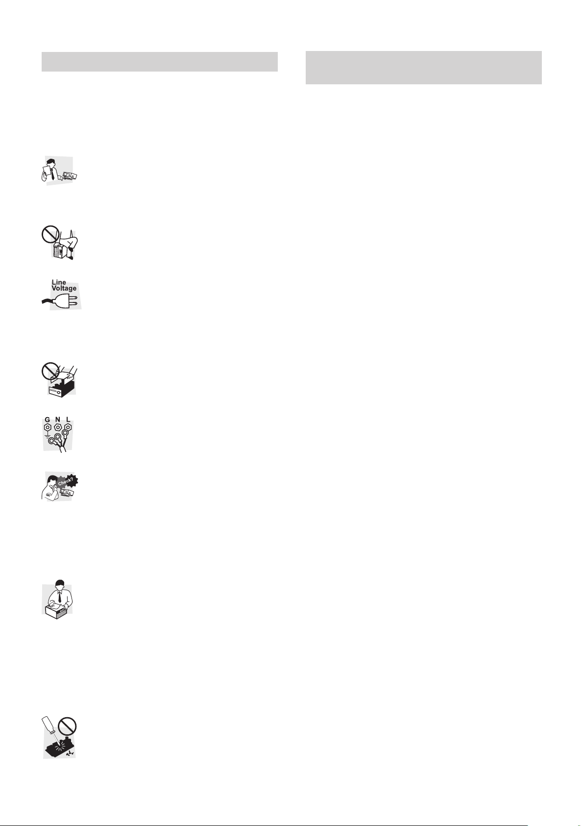
Safety Precautions
The following safety precautions must be observed to avoid fire
hazards, electric shock, accidents, and other failures. Keep them in
mind and make sure to observe them.
Using the product in a manner that is not specied in this manual
may impair the protection functions provided by the product.
Users
ration
e
Op
anual
M
Purpose
Input power
Cover
Grounding
Operation
Maintenance
and
Inspection
Adjustments
and Repairs
This product must be used only by qualied personnel
•
who understand the contents of this operation manual.
If unqualied personnel is to use the product, be sure
•
the product is handled under the supervision of quali-
ed personnel (those who have electrical knowledge).
This is to prevent the possibility of personal injury.
Never use the product for purposes other than the
•
product’s intended use.
This product is not designed or manufactured for
•
general home or consumer use.
Use the product within the rated input power volt-
•
age range.
For applying power, use the power cord provided.
•
(see page 4).
This product is designed as an equipment of IEC
•
Overvoltage Category II (energy-consuming equipment supplied from the xed installation).
Some parts inside the product may cause physical
•
hazards. Do not remove the external cover.
The rear panel may become hot during operation. If
•
you touch it, you may burn yourself.
This product is IEC Safety Class I equipment
•
(equipment with a protective conductor terminal).
To prevent electric shock, be sure to connect the
protective conductor terminal of the product to electrical ground (safety ground).
If a malfunction or abnormality is detected on the
•
product, stop using it immediately, and remove the
power plug from the outlet or turn off the circuit
breaker of switchboard. Make sure the product is
not used until it is completely repaired.
Do not disassemble or modify the product. If you
•
need to modify the product, contact your Kikusui
distributor/agent.
To prevent the possibility of electric shock, remove
•
the power plug from the outlet or turn off the circuit
breaker of switchboard before carrying out maintenance or inspection.
Check periodically that there are no tears or breaks
•
in the power cord.
If the panel needs cleaning, gently wipe it using a soft
•
cloth with water-diluted neutral detergent. Do not use
volatile chemicals such as benzene or thinner.
To maintain the performance and safe operation of
•
the product, it is recommended that periodic maintenance, inspection, cleaning, and calibration be
performed.
Kikusui service engineers will perform internal
•
service on the product. If the product needs adjustment or repairs, contact your Kikusui distributor/
agent.
Precautions Concerning Installation
Location
Be sure to observe the following precautions when installing the
product.
Do not use the product in a ammable atmosphere.
•
To prevent the possibility of explosion or re, do not use the product near alcohol, thinner, or other combustible materials, or in an
atmosphere containing such vapors.
Avoid locations where the product is exposed to high temperature
•
or direct sunlight.
Do not install the product near a heater or in areas subject to
drastic temperature changes.
Operating temperature range: 0 °C to 40 °C (+32 °F to +104 °F)
Storage temperature range: -20 °C to 70 °C (-4 °F to +158 °F)
Avoid high humidity.
•
Do not install the product in high-humidity locations--near a boiler,
humidier, or water supply.
Operating humidity range: 20 %rh to 85 %rh (no condensation)
Storage humidity range: 0 to 90 %rh (no condensation)
Condensation may occur even within the operating humidity
range. In such cases, do not use the product until the condensation dries up completely.
Be sure to use it indoors.
•
This product is designed for safe indoor use.
Do not install the product in a corrosive atmosphere.
•
Do not install the product in a corrosive atmosphere or in environments containing sulfuric acid mist, etc. This may cause corrosion
of various conductors and bad contacts of terminals inside the
power supply leading to malfunction and failure, or in the worst
case, a re.
Do not install the product in a dusty location.
•
Accumulation of dust can lead to electric shock or re.
Do not use the product where ventilation is poor.
•
The unit employs a forced air cooling system. Air is taken in from
air inlet located on panels other than the rear panel and exhausted from the air outlet on the rear panel. Secure adequate space
around the unit to prevent the possibility of re caused by accumulation of heat.
Allow at least 20 cm of space between the air inlet/outlet and the
wall (or obstacles). Hot air (approximately 20 °C higher than the
ambient temperature) is exhausted from the air outlet. Do not
place objects that are affected by heat near the air outlet.
Do not place objects on the product.
•
Placing objects on top of the product can cause failures (especially
heavy objects).
Do not install the product vertically.
•
It may cause injury to the operator or damage to the product when
it falls down.
Do not install the product on an inclined surface or location sub-
•
ject to vibrations.
The product may fall and break or cause personal injury.
Do not use the product in a location where strong magnetic or
•
electric elds are nearby or a location where large amount of distortion and noise is present on the input power supply waveform.
The product may malfunction.
Do not use the unit near highly sensitive measuring instruments
•
or transceivers.
The noise generated by the unit may affect them.
Secure adequate space around the power plug.
•
Do not insert the power plug to an outlet where accessibility to the
plug is poor. And, do not place objects near the outlet that would
result in poor accessibility to the plug.
It may cause injury to the operator or the damage to the product
when it falls down.
PLZ-4WH 3

Precautions to Be Taken When
Moving the Product
Note the following points when moving or transporting the product
to the installation location.
Turn off the power switch.
•
The product weighs over 20 kg. When moving the product, have
•
more than one person carry it. The weight of the product is in-
dicated on the rear panel of the product and in the specication
table in user’s manual.
Remove all wiring.
•
When transporting the product, be sure to use the original packing
•
Be sure to include this manual.
•
Notation Used in the Guide
In this manual, the PLZ-4WH Series Electronic Load is sometimes
•
referred to as the “PLZ-4WH Series.”
The word computer used in the text is a collective term for per-
•
sonal computers and workstations.
The following markings are used in the explanations in the text.
•
Indicates a potentially hazardous situation which, if ignored, could result in death or serious injury.
WARNING
Indicates a potentially hazardous situation which, if ignored, may result in damage to the product and other
CAUTION
property.
NOTE
Indicates information that you should know.
Connecting the Power Cord
This product is designed as an equipment of IEC Overvoltage
Category II (energy-consuming equipment supplied from the xed
installation).
Possible electric shock.
WARNING
01
02
This product is an IEC Safety Class I equipment
•
(equipment with a protective conductor terminal). Be sure
to ground (earth) the unit.
Connect the protective conductor terminal to earth
•
ground.
NOTE
Use the supplied power cord to connect to the AC line.
•
If the supplied power cord cannot be used due to the rated
voltage or the plug shape, have a qualied engineer replace
it with an appropriate power cord of length 3 m or less. If obtaining a power cord is difcult, consult your Kikusui agent
or distributor.
The power cord with a plug can be used to disconnect the
•
product from the AC line in an emergency. Connect the plug
to an easily accessible power outlet so that the plug can
be removed from the outlet at any time. Be sure to allow
enough space around the power outlet.
Do not use the supplied power cord on other instruments.
•
Check that the POWER switch is off ( ).
Check that the AC power line complies with the
input rating of the product.
The voltage that can be applied is any of the nominal power
supply voltages in the range of 100 Vac to 240 Vac. The
frequency is 50 Hz or 60 Hz.
Frequency range: 47 Hz to 63 Hz
Connect the power cord to the AC INPUT inlet on
03
the rear panel.
Insert the power plug to an grounded power outlet.
04
4 PLZ-4WH

Turning on the Power
LOAD key
Load-on indicator LED
Constant current (CC) mode is
ersion
Checking the Version
RECALL
STORE
PAUSE
LOCK
ENTER
ABC
SHIFT
POWER
I MON
LOAD
MODE
+
CV
SW ON
TRIG
OUTOUT
SET /VSET
MENU
FREQ/DUTY
Th/TL
SWITCHING
LOAD
RANGE
VRANGE
LEVEL
REMOTE
SLEW RATE
OPP /OCP
SHORT
UVP
ABC
EDIT
RUN/STOP
PRESET
SEQ
I
POWER switch
Turn off ( ) the POWER switch.
01
Check that the power cord is connected properly.
02
Make sure that nothing is connected to the DC
03
INPUT terminals (the load input terminals) on the
front and rear panel.
Turn on the POWER switch ( ).
04
Make sure that the appearance of the screen is like
05
that shown below.
The measured value displayed (section with mA, V, and W
unit) indicates coarse zero. The characters “SET” shown under
the measured value is highlighted with an underline. You can
enter the fundamental setting for the selected operation mode.
The condition in which “SET” is highlighted is called the
“fundamental setting entry condition.”
H 8.25A 650V
0.00mA0.000V
0.000W
3.0000
mA/µs
A
SET
CC
SLEWRATE
Press LOAD so that the LED above it lights.
06
Press LOAD again so that the LED above it turns
07
0.01
off.
Turn off ( ) the POWER switch. The operation
08
check procedure is nished.
This product has a backup feature in which it saves the
settings when the power is turned off. When you turn the
power on, the backed up settings are restored.
Wait for at least 5 seconds after you turn off the power
before you turn it on again. Failure to do so could cause
CAUTION
damage to the product.
selected in this screen, so you
can enter the current, which is
the fundamental setting.
Model Information
[ PLZ164WH ]
VERSION
SUB 1.00
MAIN 1.02
PREV
Press MENU (SHIFT + SET/VSET).
01
Firmware v
ROM version
The menu screen appears.
Use the cursor keys to select 4. Model Info.
02
The selected item is highlighted.
Press ENTER.
03
The Model Information screen shown above appears.
Press MENU (SHIFT + SET/VSET) to close the
04
menu.
Load Wiring
Use load wiring with a diameter that is appropriate
for the amount of current being used and with sturdy,
CAUTION
incombustible or ame-resistant insulation.
If the wiring that you use for the load has a high resistance, the volt-
age will drop signicantly when current ows, and the voltage at the
load input terminals may fall below the minimum operating voltage.
Using the following table as a reference, select wiring that is as thick
as possible.
Nominal
Cross-
Sectional
Area
[mm
100 4/0 (107.2) 298 —
125 — — 344 —
150 — — 395 300
200 — — 469 —
250 — — 556 —
325 — — 650 —
* Excerpt from Japanese laws related to electrical equipment.
AWG (reference
2
]
2 14 (2.08) 27 10
3.5 12 (3.31) 37 —
5.5 10 (5.26) 49 20
8 8 (8.37) 61 30
14 6 (13.3) 88 50
22 4 (21.15) 115 80
30 2 (33.62) 139 —
38 1 (42.41) 162 100
50 1/0 (53.49) 190 —
60 2/0 (67.43) 217 —
80 3/0 (85.01) 257 200
cross-
sectional
area)
[mm
Allowable current
2
]
[A]*
(Ta = 30 °C)
Kikusui-
Recommended
Current
[A]
PLZ-4WH 5

Inductance of the Load Wiring
Vo
Example of waveform
Short, 100 cm or less
Example: R = 10 Ω, C = 100 µF
Generally, a wire’s inductance is approximately 1 µH per meter of
wire. If the DUT and the electronic load are connected using 1 m of
wire (total length of the positive and negative wiring), a change in
current of 50 A/µs will generate a voltage of 500 V.
The negative load input terminal provides the reference potential for
the external control signal. The generated voltage may cause the
device connected to the external control signal to malfunction.
When the electronic load is in constant-voltage, constant-resistance,
or constant-power mode, it uses the voltage at the load input terminals to change the load current. So it is easy for the electronic load
to be inuenced by the generated voltage.
Make the wiring to the DUT as short as possible, and twist it.
If the instantaneous voltage value at the load input terminals drops
below the minimum operating voltage, the recovery response will
be delayed signicantly. You need to be especially careful when the
slew rate setting is high and when switching operation is performed
at high currents.
ΔI
Current
ltage across
the load input
terminals
This change results
in unstable oscillation
and hunting.
ΔT
Minimum operating
voltage
Voltage across
the load input
terminals
Current
Results of Changing the Response Speed
You can change the response speed in CC mode, CV mode, and
CR mode. The wiring inductance can cause the current to lag the
voltage. This can result in unstable control of the PLZ-4WH and oscillation.
To ensure stable operation, reduce the response speed.
Overvoltage
Do not apply a voltage that is greater than the maximum
voltage of 650 Vdc to the load input terminals. Doing so
CAUTION
could damage the product.
When excessive voltage is applied, the protection functions are acti-
vated. Lower the voltage of the DUT immediately.
H 8.25A 650V
100.00A150.00
CC
SLEWRATE
ALARM
OVP
16.50
W
ENTER
SET
2.50 m
0.000
A /µs
V
A
Polarity
Connecting the electronic load to the DUT with the polarities
reversed can result in the flow of excessive current and
CAUTION
damage to the DUT and the electronic load.
You need to be especially careful when the slew rate setting is high
and when parallel operation results in switching at high currents.
To make sure that the voltage resulting from inductance remains
within the range of the electronic load’s minimum operating voltage
and maximum input voltage, make the wiring as short as possible,
twist the wiring, or set a low slew rate.
If it is not necessary to operate at a high response speed, reduce
the slew rate in CC mode, or reduce the response speed in CR
mode.
During DC operation, it is also possible for the phase lag of the
current to result in unstable electronic load control and oscillation.
Make the wiring as short as possible, and twist it. If you only need to
use DC operation, connecting a capacitor and a resistor to the load
input terminals as shown in the gure below can reduce oscillation.
If you do this, do not exceed the capacitor’s ripple-current rating.
+
DUT
–
Twist
+
R
C
PLZ-4WH
Series
–
Connect each load input terminal to the terminal on the DUT with
the same polarity.
+ +
DUT
≤650 Vdc
-
-
PLZ-4WH
Series
The protection functions are activated when a reverse voltage of ap-
proximately 0.4 V or greater is applied. If this happens, turn off the
DUT immediately.
H 8.25A 650V
ALARM
0.00mA0.000
Reverse
0.000
SET
CC
SLEWRATE
W
ENTER
25.0
0.000
V
A
µA /µs
6 PLZ-4WH

Гхффиеумеецефп
Insert the lock plates
Move the cover until it touches
the panel, and then pinch in the
Connecting to the Load Input Terminal
To avoid electric shock, observe the following precautions.
WARNING
Do not touch the load input terminals when the output is
•
turned on.
The load input terminals on the front panel are connected
•
internally to the load input terminals on the rear panel. The
voltage applied to the terminal on one side is transmitted
directly to the terminal on the other side.
To avoid damaging the product, observe the following
CAUTION
precautions. Do not connect the DUT to the DC INPUT
•
terminals when the load is on.
Do not connect devices to the load input terminals on the
•
front panel and those on the rear panel at the same time.
To avoid overheating, observe the following precautions.
Attach crimping terminals to the wires, and use the at-
•
tached screw set to connect them.
Connection to the Load Input Terminal on the
Rear Panel
Pass the wiring that you want to connect to the
05
load through the load input terminal cover.
Connect the load wiring to the load input terminals
06
using the load input terminal screw set that came
with the PLZ-4WH.
Bolts (M8 x18)
Spring washers (M8)
Use the lock plates to fix the load input terminal
07
Crimping terminal
Load input terminal cover
Be sure to use the included
screw set.
Nuts (M8)
cover to the rear panel.
To x the cover in place, insert the lock plate pins through the
holes on the side of the cover.
To avoid electric shock, observe the following precautions.
WARNING
Always use the load input terminal cover.
•
Using the Load Input Terminal Cover
Pass the wiring that you intend to connect to the load through the
load input terminal cover. Cut the cover’s sleeves to match the thickness of the wiring’
ij±µìéîå
ij²µìéîå
Connection Procedure
Turn off ( ) the POWER switch.
01
Make sure that the output of the DUT is off.
02
Attach the lock plates.
03
ij±°ìéîå
ij²°ìéîå
The lock plates are for xing the load input terminal cover to
the rear panel. After you attach them once, there is no need to
remove them.
нбфгифиечйте
дйбнефетвщ
хуйозфиезбхзе
бубтежетеое®
direction of the arrows so that
the side of the cover sticks out.
Top view
While the side of the cover
Connect the load wires to the output terminals of
08
is sticking out, insert the lock
plate pin into the hole.
Make sure that the left and
right lock-plate pins are
inserted securely into the cover
holes.
the DUT.
Connect the positive load input terminal to the positive terminal
of the DUT, and connect the negative load input terminal to the
negative terminal of the DUT.
Attach crimping terminals to the load wiring.
04
The DC INPUT terminals on the rear panel have open bolt
holes (M8) for connecting the load wiring. Attach appropriate
crimping terminals.
PLZ-4WH 7
into the slots by the
terminals.
Lock plate

Connecting to the Load Input
Spring
washers (M6)
that it passes through
Remote sensing terminals
Terminal (Cont'd)
Connecting to the Load Input Terminals on
the Front Panel
The load input terminals on the front panel enable you to connect
the DUT and the electronic load easily.
The specications of the electronic load are for the load input termi-
nals on the rear panel.
To avoid electric shock, observe the following precautions.
WARNING
Always use the load input terminal cover.
•
Turn off ( ) the POWER switch.
01
Make sure that the output of the DUT is off.
02
Connect the wires to the load input terminals on
03
the front panel.
Remote Sensing
When the load wiring is long, the voltage drop caused by the wiring’
s resistance cannot be ignored. “Remote sensing” is a function that
can be used to compensate for this voltage drop. To accurately set
the resistance, voltage, and power, use remote sensing.
Remote sensing makes operation more stable by improving the
transient characteristics in the constant-resistance (CR), constant-
voltage (CV), and constant-power (CP) modes.
Never wire the sensing terminals while the POWER
•
CAUTION
switch is turned on. Doing so may damage the internal
circuitry.
If a wire is disconnected during remote sensing, the PLZ-
•
4WH and the DUT may be damaged. Make sure that
wire connections are secure.
ᴨÓ
Red
ᴪÓ
White
DUT
ᴨ
Twist
PLZ-4WH Series
ᴨ
Electronic Load
Knob
Cover
Connect the load wires to the output terminals of
04
M6
Crimping terminal
with insulating cap
Attach the wire so
this section.
the DUT.
Connect the positive load input terminal to the positive terminal
of the DUT, and connect the negative load input terminal to the
negative terminal of the DUT.
–
Turn the POWER switch off.
01
Connect the sensing terminals to the DUT using
02
–
sensing wires.
Connect the positive remote sensing terminal on the rear
panel (+S) to the positive terminal (+) on the DUT. In the same
way, connect the negative remote sensing terminal (-S) on the
rear panel to the negative terminal (-) on the DUT. Connect the
wiring as close to the DUT as possible.
8 PLZ-4WH

Remote Control
Contents of the Included CD-ROM
In addition to controlling the electronic load from the front panel, you
can also control it remotely using a communication interface.
For details about remote control, see the Communication Interface
Manual. The Communication Interface Manual is included in the
CD-ROM.
About the VISA Library
The VISA library is necessary for the use of the PLZ applications
and samples.
To use the USB port to control the electronic load, you must install a
driver that supports the USB Test & Measurement class (USBTMC)
on the controller. The USBTMC driver is included in the VISA library.
VISA (Virtual Instrument Software Architecture) was developed by
the VXIplug&play Systems Alliance. It is the standard specication
for measurement instrument connection software.
You have to install one of the following VISA libraries (driver software that is implemented according to the VISA specications).
Do not install multiple VISA libraries on the same PC. Doing so may
cause errors.
VISA libraries that are older than the versions listed below do not
support USB.
NI-VISA by National Instruments Corporation (version 3.0 or later;
•
version 3.2 or later for Windows 2000, Windows XP or Windows 7)
Agilent VISA by Agilent Technologies, Inc. (Agilent IO Libraries
•
M.01.00 or later)
KI-VISA version 3.0.0 or later
•
Command Details
For details on commands, see the Communication Interface Manual
on the supplied CD-ROM.
The Communication Interface Manual is provided in HTML format.
You can view the manual using the following browser.
Operating environment: Windows 98 or later
Browser: Microsoft Internet Explorer 5.5 or later
The list of messages in the Communication Interface Manual is
provided in PDF format. You can view it using Adobe Reader 6.0 or
later.
Put the included CD-ROM into the CD-ROM drive. A start window
will appear momentarily. If the start window does not appear, open
the CD-ROM in Windows Explorer, and then double-click index.html
to display the start window.
PLZ Applications & Samples
The PLZ applications & samples include the following software.
VPanel A simple virtual panel
Monitor And Log Measures and logs current, voltage, and
Step Editor A sequence editor
Memory Copy A setup-memory backup tool
The VISA library is necessary for the use of these applications.
Use the CD-ROM menu program or Windows
01
Explorer to open the app folder.
Double-click PlzAppsSetup_x_x_x.exe.
02
The numbers that appear instead of the x’s vary depending on
the application revision number.
power
Follow the displayed instructions to proceed with
03
the installation.
For details, see Readme_e.htm in the application folder.
PLZ-4WH 9

Contents of the Included CD-ROM
10
(Cont'd)
KI-VISA
KI-VISA is an original VISA library developed by Kikusui Electron-
ics Corporation that supports the VXIplug&play VISA specications.
You can download the most recent version of this library from the
Kikusui Electronics Corporation website (http://www.kikusui.co.jp/en/
download/).
If NI-VISA or Agilent VISA is already installed on your PC, you do
not need to install KI-VISA.
Use the CD-ROM menu program or Windows
01
Explorer to open the VISA folder.
Trademarks
Microsoft and Windows are either registered trademarks or trademarks of Microsoft Corporation in the United States and/or other
countries.
Other company names and product names used in this manual are
generally trademarks or registered trademarks of the respective
companies.
Copyrights
Reproducing or reprinting this operation manual or any part of it
without the permission of the copyright holder is strictly prohibited.
Product specications and manual contents are subject to change
without notice.
© 2010 Kikusui Electronics Corporation
Double-click Kivisa_x_x_x.exe.
02
The numbers that appear instead of the x’s vary depending on
the application revision number.
Follow the displayed instructions to proceed with
03
the installation.
After you install KI-VISA, the KI-VISA Instrument Explorer
opens.
Click KI-VISA Cong.
04
Click the USB(USBTMC) tab and then Run Driver
05
Wizard(WINUSB.SYS).
Uncheck the Protect my computer and data from
06
unauthorized program activity check box, and then
click OK.
Uncheck
Follow the displayed instructions to install the
07
USBTMC driver.
Inquiry about Product
When making an inquiry about the product, please provide us with
the following information.
Model (indicated at the top section on the front panel)
Firmware version (see page 5)
Serial number (indicated at the bottom section on the rear panel)
环境保护使用期限
Environment-friendly Use Period
该标记为适用于在中华人民共和国销售的电子信息产品的环境保
护使用期限。
只要遵守有关该产品的安全及使用注意事项,从制造年月起计算,
在该年度内,就不会对环境污染、人身、财产产生重大的影响。
产品的废弃请遵守有关规定。
产品的制造年月可以在以下网址中确认。
http://www.kikusui.co.jp/pi/
有毒有害物质或元素名称及含有標示
Name of hazardous materials and symbol of element in the
部件名称
印刷电路板组装品 × ○ ○ ○ ○ ○
显示器 × ○ ○ ○ ○ ○
内部接线 ○ ○ ○ ○ ○ ○
外壳 × ○ ○ ○ ○ ○
底盘组装品 × ○ ○ ○ ○ ○
辅助设备 ○ ○ ○ ○ ○ ○
equipment and quantity
有毒有害物质或元素
铅Pb汞Hg镉Cd六价铬
Cr(VI)
多溴联
苯
PBB
多溴二
苯醚
PBDE
本表格依据
Manuals
The Setup Guide (PDF), the Quick reference (PDF), the User’s
Manual (PDF) and the Communication Interface Manual (HTML)
are included.
10 PLZ-4WH
○
×
: 该部件至少有一种均质材料的有毒有害物质的含量超过
SJ/T 11364
: 该部件所有均质材料的有毒有害物质的含量不超过
准所规定的极限值要求。
标准所规定的极限值要求。
的规定编制。
GB/T 26572
GB/T 26572
标
 Loading...