


Part No. IB020915
Oct. 2015
USERS MANUAL
ELECTRONIC LOAD PLZ-4W Series
PLZ 164 W
PLZ 164 WA
PLZ 334 W
PLZ 664 WA
PLZ 1004 W

About the PLZ-4W series Manuals
Manual construction
Setup Guide
The setup guide is intended for first-time users of the PLZ-4W series. It gives an overview of the PLZ4W series, connecting procedures, safety precautions, etc. Please read through and understand this
guide before operating the product.
Quick Reference
The quick reference briefly explains the panel description and the basic operation of the PLZ-4W.
User’s Manual (This manual, PDF)
User’s manual is intended for first-time users of the PLZ-4W series. It gives an overview of the PLZ4W series and describes various settings, measurement procedures, maintenance, safety precautions,
etc.
Communication Interface Manual (HTML, partially PDF)
The Communication Interface Manual explains the settings and commands for remotely controlling the
PLZ-4W series, using the communication interface and gives sample programs.
The interface manual is written for readers with sufficient basic knowledge of how to control instruments using a personal computer.
PDF and HTML files are included in the accompanying CD-ROM.
Adobe Reader 9.2 or later is required to view the PDF files.
Microsoft Internet Explorer 9 or later is required to view the HTML files.
Please read through and understand the Operation Manual before operating the product. After reading,
always keep the manuals nearby so that you may refer to it as needed. When moving the product to another
location, be sure to bring the manuals as well.
If you find any incorrectly arranged or missing pages in the manual, they will be replaced. If the manual
gets lost or soiled, a new copy can be provided for a fee. In either case, please contact Kikusui distributor/
agent, and provide the “Kikusui Part No.” given on the cover.
The Operation Manual has been prepared with the utmost care; however, if you have any questions, or note
any errors or omissions, please contact Kikusui distributor/agent.
Firmware versions that this manual covers
This manual covers firmware versions 1.4X.
When contacting us about the product, please provide us with:
The model (marked in the top section of the front panel)
The firmware version (see page 2-9)
The serial number (marked on the rear panel)
Trademarks
Microsoft and Windows are either registered trademarks or trademarks of Microsoft Corporation in the
United States and/ or other countries.
Other company names and product names used in this manual are generally trademarks or registered trademarks of the respective companies.
Copyrights
Reproduction and reprinting of operation manual, whole or partially, without our permission is prohibited.
Both unit specifications and manual contents are subject to change without notice.
Copyright© 2010 Kikusui Electronics Corporation

Contents
Chapter 1 General Information 1-1
Chapter 2 Installation and Preparation 2-1
1.1 About This Manual - - - - - - - - - - - - - - - - - - - - - - - - - - - - - - - - - - - - - 1-2
1.2 Product Overview - - - - - - - - - - - - - - - - - - - - - - - - - - - - - - - - - - - - - - 1-2
1.3 PLZ-4W Series Lineup - - - - - - - - - - - - - - - - - - - - - - - - - - - - - - - - - - 1-3
1.4 Features - - - - - - - - - - - - - - - - - - - - - - - - - - - - - - - - - - - - - - - - - - - - - 1-4
1.5 Overview of Controls - - - - - - - - - - - - - - - - - - - - - - - - - - - - - - - - - - - 1-6
1.6 Options - - - - - - - - - - - - - - - - - - - - - - - - - - - - - - - - - - - - - - - - - - - - - 1-8
2.1 Checking the Package Contents - - - - - - - - - - - - - - - - - - - - - - - - - - - - - 2-2
2.2 Precautions Concerning Installation Location - - - - - - - - - - - - - - - - - - - 2-3
2.3 Precautions When Moving the Unit - - - - - - - - - - - - - - - - - - - - - - - - - - 2-4
2.4 Connecting the Power Cord - - - - - - - - - - - - - - - - - - - - - - - - - - - - - - - 2-5
2.5 Grounding (Earth) - - - - - - - - - - - - - - - - - - - - - - - - - - - - - - - - - - - - - - 2-6
2.6 Turning on The Power - - - - - - - - - - - - - - - - - - - - - - - - - - - - - - - - - - - 2-7
2.7 Checking the ROM Version - - - - - - - - - - - - - - - - - - - - - - - - - - - - - - - 2-9
2.8 Load Wiring - - - - - - - - - - - - - - - - - - - - - - - - - - - - - - - - - - - - - - - - - 2-10
2.8.1 Precautions Concerning Wiring - - - - - - - - - - - - - - - - - - - - - - - 2-10
2.8.2 Connection to the Load Input Terminal on the Rear Panel - - - - - 2-14
2.8.3 Connection to the Load Input Terminal on the Front Panel - - - - 2-17
Chapter 3 For First Time Users 3-1
3.1 What Is an Electronic Load - - - - - - - - - - - - - - - - - - - - - - - - - - - - - - - - 3-2
3.2 Basic Flow of Operation - - - - - - - - - - - - - - - - - - - - - - - - - - - - - - - - - - 3-3
3.3 Operating area of the PLZ-4W - - - - - - - - - - - - - - - - - - - - - - - - - - - - - 3-6
3.4 Basic Operation Modes - - - - - - - - - - - - - - - - - - - - - - - - - - - - - - - - - - 3-7
3.4.1 Operation of the CC Mode - - - - - - - - - - - - - - - - - - - - - - - - - - - 3-7
3.4.2 Let's Use CC Mode - - - - - - - - - - - - - - - - - - - - - - - - - - - - - - - - 3-9
Chapter 4 Names and Functions of Parts 4-1
4.1 Front Panel - - - - - - - - - - - - - - - - - - - - - - - - - - - - - - - - - - - - - - - - - - 4-2
4.2 Rear Panel - - - - - - - - - - - - - - - - - - - - - - - - - - - - - - - - - - - - - - - - - - - 4-4
4.3 Operation Panel - - - - - - - - - - - - - - - - - - - - - - - - - - - - - - - - - - - - - - - 4-6
4.4 Display - - - - - - - - - - - - - - - - - - - - - - - - - - - - - - - - - - - - - - - - - - - - 4-12
Chapter 5 Basic Operation 5-1
5.1 Panel Control Basics - - - - - - - - - - - - - - - - - - - - - - - - - - - - - - - - - - - - 5-2
5.2 Turning On or Off the Load - - - - - - - - - - - - - - - - - - - - - - - - - - - - - - - 5-3
5.3 Types of Protection Functions - - - - - - - - - - - - - - - - - - - - - - - - - - - - - - 5-6
5.4 Setting the Protection Function - - - - - - - - - - - - - - - - - - - - - - - - - - - - - 5-8
5.5 Operation Modes - - - - - - - - - - - - - - - - - - - - - - - - - - - - - - - - - - - - - - 5-9
PLZ-4W Contents 3

5.6 CC Mode - - - - - - - - - - - - - - - - - - - - - - - - - - - - - - - - - - - - - - - - - - - 5-10
5.7 CR Mode - - - - - - - - - - - - - - - - - - - - - - - - - - - - - - - - - - - - - - - - - - - 5-13
5.8 CV Mode - - - - - - - - - - - - - - - - - - - - - - - - - - - - - - - - - - - - - - - - - - - 5-16
5.9 CP Mode - - - - - - - - - - - - - - - - - - - - - - - - - - - - - - - - - - - - - - - - - - - 5-18
5.10 Soft start - - - - - - - - - - - - - - - - - - - - - - - - - - - - - - - - - - - - - - - - - - - 5-20
5.11 Lock Function - - - - - - - - - - - - - - - - - - - - - - - - - - - - - - - - - - - - - - - - 5-22
5.12 Short Function - - - - - - - - - - - - - - - - - - - - - - - - - - - - - - - - - - - - - - - 5-24
5.13 Menu Setup - - - - - - - - - - - - - - - - - - - - - - - - - - - - - - - - - - - - - - - - - 5-25
5.14 Initialization - - - - - - - - - - - - - - - - - - - - - - - - - - - - - - - - - - - - - - - - - 5-28
5.15 Response Speed - - - - - - - - - - - - - - - - - - - - - - - - - - - - - - - - - - - - - - 5-29
Chapter 6 Applied Operation 6-1
6.1 ABC preset memories - - - - - - - - - - - - - - - - - - - - - - - - - - - - - - - - - - - 6-2
6.1.1 Saving to ABC preset memories - - - - - - - - - - - - - - - - - - - - - - - 6-3
6.1.2 Recalling ABC preset memories - - - - - - - - - - - - - - - - - - - - - - - - 6-3
6.2 Setup Memory - - - - - - - - - - - - - - - - - - - - - - - - - - - - - - - - - - - - - - - - 6-6
6.2.1 Saving to the Setup Memory - - - - - - - - - - - - - - - - - - - - - - - - - - 6-7
6.2.2 Recalling the Setup Memory - - - - - - - - - - - - - - - - - - - - - - - - - - 6-8
6.3 Switching Function - - - - - - - - - - - - - - - - - - - - - - - - - - - - - - - - - - - - 6-10
6.4 Setting the Slew Rate - - - - - - - - - - - - - - - - - - - - - - - - - - - - - - - - - - - 6-12
6.5 Using the Elapsed Time Display and the Auto Load Off Timer - - - - - - - 6-13
6.6 Sequence Function - - - - - - - - - - - - - - - - - - - - - - - - - - - - - - - - - - - - - 6-14
6.6.1 Overview of the Normal Sequence - - - - - - - - - - - - - - - - - - - - - 6-15
6.6.2 Sequence Editing - - - - - - - - - - - - - - - - - - - - - - - - - - - - - - - - 6-18
6.6.3 Sequence Example (Normal Sequence) - - - - - - - - - - - - - - - - - 6-21
6.6.4 Overview of the Fast Sequence - - - - - - - - - - - - - - - - - - - - - - - 6-27
6.6.5 Fast Sequence Editing - - - - - - - - - - - - - - - - - - - - - - - - - - - - - 6-29
6.6.6 Sequence Example (Fast Sequence) - - - - - - - - - - - - - - - - - - - - 6-31
6.6.7 Executing, Pausing, Stopping the Sequence - - - - - - - - - - - - - - - 6-36
6.7 Remote Sensing Function - - - - - - - - - - - - - - - - - - - - - - - - - - - - - - - - 6-38
6.8 External Control - - - - - - - - - - - - - - - - - - - - - - - - - - - - - - - - - - - - - - 6-39
6.8.1 Overview and Precaution of External Control - - - - - - - - - - - - - - 6-39
6.8.2 J1/J2 connector - - - - - - - - - - - - - - - - - - - - - - - - - - - - - - - - - - 6-40
6.8.3 External Control of CC Mode - - - - - - - - - - - - - - - - - - - - - - - - 6-44
6.8.4 External Control of CR Mode - - - - - - - - - - - - - - - - - - - - - - - - 6-50
6.8.5 External Control of CP Mode - - - - - - - - - - - - - - - - - - - - - - - - 6-52
6.8.6 External Control of CV Mode - - - - - - - - - - - - - - - - - - - - - - - - 6-54
6.8.7 External Control of Load On and Load Off - - - - - - - - - - - - - - - 6-56
6.8.8 Trigger Signal Control - - - - - - - - - - - - - - - - - - - - - - - - - - - - - 6-57
6.8.9 External Control of the Current Range - - - - - - - - - - - - - - - - - - 6-58
6.8.10 Alarm Signal Control - - - - - - - - - - - - - - - - - - - - - - - - - - - - - 6-59
6.9 Monitor Signal Output - - - - - - - - - - - - - - - - - - - - - - - - - - - - - - - - - - 6-60
6.10 Parallel operation - - - - - - - - - - - - - - - - - - - - - - - - - - - - - - - - - - - - - - 6-62
6.10.1 Parallel Operation Using the Same Model - - - - - - - - - - - - - - - - 6-62
6.10.2 Parallel Operation Using Load Boosters - - - - - - - - - - - - - - - - - 6-65
6.10.3 Alarms during Parallel Operation - - - - - - - - - - - - - - - - - - - - - 6-66
4 Contents PLZ-4W

6.10.4 Response Speed during Parallel Operation - - - - - - - - - - - - - - - - 6-66
6.10.5 Slew Rate during Parallel Operation - - - - - - - - - - - - - - - - - - - - 6-66
6.10.6 Canceling the Parallel Operation - - - - - - - - - - - - - - - - - - - - - - 6-66
Chapter 7 Remote Control 7-1
7.1 Overview - - - - - - - - - - - - - - - - - - - - - - - - - - - - - - - - - - - - - - - - - - - - 7-2
7.2 Interface Setup - - - - - - - - - - - - - - - - - - - - - - - - - - - - - - - - - - - - - - - - 7-3
7.2.1 GPIB Control - - - - - - - - - - - - - - - - - - - - - - - - - - - - - - - - - - - - 7-3
7.2.2 RS232C Control - - - - - - - - - - - - - - - - - - - - - - - - - - - - - - - - - - 7-4
7.2.3 USB Control - - - - - - - - - - - - - - - - - - - - - - - - - - - - - - - - - - - - 7-6
7.3 Contents of the accompanying CD-ROM - - - - - - - - - - - - - - - - - - - - - - 7-7
7.3.1 Installing the VISA Library - - - - - - - - - - - - - - - - - - - - - - - - - - 7-8
7.3.2 Installing the Software Application - - - - - - - - - - - - - - - - - - - - 7-10
7.4 Command Details - - - - - - - - - - - - - - - - - - - - - - - - - - - - - - - - - - - - - 7-10
Chapter 8 Maintenance and Calibration 8-1
8.1 Maintenance - - - - - - - - - - - - - - - - - - - - - - - - - - - - - - - - - - - - - - - - - - 8-2
8.1.1 Cleaning the Panels - - - - - - - - - - - - - - - - - - - - - - - - - - - - - - - - 8-2
8.1.2 Cleaning the Dust Filter - - - - - - - - - - - - - - - - - - - - - - - - - - - - - 8-2
8.1.3 Inspecting the Power Cord - - - - - - - - - - - - - - - - - - - - - - - - - - - 8-3
8.1.4 Internal Inspection - - - - - - - - - - - - - - - - - - - - - - - - - - - - - - - - - 8-3
8.2 Confirming status of the fuse - - - - - - - - - - - - - - - - - - - - - - - - - - - - - - 8-4
8.3 Calibration - - - - - - - - - - - - - - - - - - - - - - - - - - - - - - - - - - - - - - - - - - - 8-5
8.3.1 Calibration Overview - - - - - - - - - - - - - - - - - - - - - - - - - - - - - - - 8-5
8.3.2 Preparation - - - - - - - - - - - - - - - - - - - - - - - - - - - - - - - - - - - - - 8-6
8.3.3 Calibration Procedure - - - - - - - - - - - - - - - - - - - - - - - - - - - - - - 8-7
8.4 Malfunctions and Causes - - - - - - - - - - - - - - - - - - - - - - - - - - - - - - - - 8-14
Chapter 9 Specifications 9-1
9.1 Electrical Specifications - - - - - - - - - - - - - - - - - - - - - - - - - - - - - - - - - - 9-2
9.2 General Specifications ----------------------------- 9-8
9.3 Dimensions - - - - - - - - - - - - - - - - - - - - - - - - - - - - - - - - - - - - - - - - - 9-10
Appendix A-1
A.1 Operating Area of the PLZ-4W - - - - - - - - - - - - - - - - - - - - - - - - - - - - - A-1
A.2 Basic Operation Modes - - - - - - - - - - - - - - - - - - - - - - - - - - - - - - - - - - A-2
A.2.1 Operation of the CC Mode - - - - - - - - - - - - - - - - - - - - - - - - - - A-2
A.2.2 Operation of the CR Mode - - - - - - - - - - - - - - - - - - - - - - - - - - - A-4
A.2.3 Operation of the CP Mode - - - - - - - - - - - - - - - - - - - - - - - - - - - A-6
A.2.4 Operation of the CV Mode - - - - - - - - - - - - - - - - - - - - - - - - - - - A-8
A.2.5 Operation of the CC+CV Mode - - - - - - - - - - - - - - - - - - - - - - A-10
A.2.6 Operation of the CR+CV Mode - - - - - - - - - - - - - - - - - - - - - - A-12
A.3 Operating Area of Each Model - - - - - - - - - - - - - - - - - - - - - - - - - - - - A-15
A.3.1 Operating Area of the PLZ164W - - - - - - - - - - - - - - - - - - - - - - A-15
PLZ-4W Contents 5

A.3.2 Operating Area of the PLZ334W - - - - - - - - - - - - - - - - - - - - - - A-16
A.3.3 Operating Area of the PLZ1004W - - - - - - - - - - - - - - - - - - - - - A-17
A.3.4 Operating Area of the PLZ164WA - - - - - - - - - - - - - - - - - - - - A-18
A.3.5 Operating Area of the PLZ664WA - - - - - - - - - - - - - - - - - - - - A-19
A.4 Sequence Program Creation Table - - - - - - - - - - - - - - - - - - - - - - - - - - A-20
Index I- 1
6 Contents PLZ-4W

Chapter 1 General Information
1
1
This chapter gives an overview and introduces the features of the PLZ-4W Series
Electronic Loads.
PLZ-4W General Information 1-1

1.1 About This Manual
This operation manual covers the following PLZ-4W Series Electronic Loads.
• PLZ164W • PLZ164WA
• PLZ334W • PLZ664WA
• PLZ1004W
Product version covered
This operation manual covers electronic loads with ROM version 1.3x.
When contacting us about the product, please provide us the following information.
• Model
• ROM version
• Manufacturing number (indicated at the lower section on the rear panel)
For the procedure of confirming the ROM version, see section 2.7, ?Checking the
ROM Version.”
1.2 Product Overview
The PLZ-4W Series Electronic Load is a multifunctional system designed to offer
the highest levels of reliability and safety. The electonic load contains a stable and
high-performance current control circuit that enables high-speed load simulations.
In addition, its CPU control feature works to improve operability and multifunctional capability.
The high-precision current settings provide you with sufficient resolution.
Because the electonic load comes standard with GPIB, RS232C, and USB commu-
nication functions, it can easily be incorporated into wide-ranging test and inspection systems.
1-2 General Information PLZ-4W

1.3 PLZ-4W Series Lineup
The PLZ-4W Series consists of the electronic load and the load
booster.
1. Electronic load (PLZ-4W or PLZ-4WA)
2. Load booster (PLZ-4WB)
Two types of the PLZ-4W Series are available depending on the
input operating voltage.
1. Operating range of 1.5 V to 150 V. (PLZ-4W and PLZ-4WB)
2. Operating range of 0 V to 150 V. (PLZ-4WA)
■ Electronic load
Model
PLZ164W 33
PLZ334W 66 330
PLZ1004W 200 1 000
PLZ164WA 33
PLZ664WA 132 660
■ Load booster
Model
PLZ2004WB
*1. PLZ2004WB is a dedicated option for PLZ1004W.
*1
Maximum Operating
Current (A)
Maximum Operating
Current (A)
400 1.5 to 150 2 000
Operating
Voltage (V)
1.5 to 150
0 to 150
Operating
Voltage (V)
Wattage (W)
165
165
Wattage (W)
PLZ-4W General Information 1-3

1.4 Features
In addition to the high-performance constant current, constant resistance, and constant power modes, the PLZ-4W Series Electronic Load offers wide variety of other
features.
■ High-speed slew rate of 16 A/s (PLZ1004W)
The rise and fall slew rate of the current when switching at 2 % to 100 % (20 % to
100 % in M range) of the rated current in constant current mode is 16 A/s
(PLZ1004W), which converts to rise and fall times of 10 s (all types).
This allows you to conduct more accurate DC power transient response tests and to
generate simulated waveforms for use as dummy loads.
■ Variable slew rate
Unlike the conventional electronic loads that were configured using rise and fall
times, the PLZ-4W allows configuration using slew rates (A/s) in constant current
and constant resistance modes.
This allows you to optimize the voltage drop caused by the wire inductance that
occurs when a load is switched or the transient control of the equipment under test
(such as a constant voltage power supply).
■ Higher precision
Higher precision is offered for current settings.
Resolution at low current settings is provided using a 3-range configuration. (A 0.01
mA resolution is possible at the L range of the PLZ164W.)
■ Operability
The PLZ-4W employs a large LCD.
Measured values of voltage, current, and power at the load input terminal are indi-
cated at all times. The values are indicated using larger characters than other sections to improve the visibility.
Coarse and fine adjustments using the rotary knob are useful for setting values over
a wide range.
The easy-to-use memory function enables repetitive tests.
■ 0 V input type
A 0 V input operating voltage type is available.
This feature is a must for single cell tests of fuel cells. Moreover, the operating volt-
age of semiconductor devices is decreasing more and more due to the reduction of
the power consumption and miniaturization of the semiconductor process. The 0 V
input type can be used to evaluate the power supplies for these types of applications.
■ Sequence function
Sequence patterns set arbitrarily can be saved to built-in memory.
Up to 10 normal sequence programs and 1 fast sequence program can be saved. Up
to 256 steps and 1024 steps can be saved for each normal sequence program and fast
sequence program, respectively.
1-4 General Information PLZ-4W

The sequence pattern can be edited easily using the large LCD.
■ Useful function for battery discharge tests
The PLZ-4W can measure the time from load on to load off.
When combined with the under voltage protection (UVP) function, the time from
when the battery discharge is started until the battery voltage falls to the cutoff voltage can be measured (time measurement).
In voltage measurement, the voltage immediately before the load turns off is measured. If you set a timer to turn off the load after a specified time elapses, you can
measure the closed circuit voltage after a specified time elapses from the start of
battery discharge (voltage measurement).
■ Load booster
To achieve large capacity at low cost, the PLZ1004W comes with a load booster
(PLZ2004WB).
Using a single PLZ1004W as a master unit, up to four load boosters can be connected in parallel (9 kW, 1 800 A maximum).
■ Standard GPIB, RS232C, and USB communication functions
Because the electonic load comes standard with GPIB, RS232C, and USB communication functions, it can easily be incorporated into wide-ranging test and inspection systems.
Wide variety of systems can be configured when combined with the sequence function.
PLZ-4W General Information 1-5
1.5 Overview of Controls
AC INPUT
100-240V
47
-
63Hz
160VA MAX
KCC-REM-KEJ
PLZ-78270
2012/05
AC INPUT
100-240V
47
-
63Hz
160VA MAX
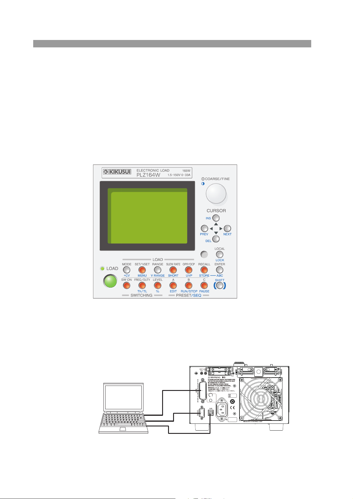
This section describes the controls on the electronic load and combined systems.
Operation using the control panel
The PLZ-4W employs a large LCD. Measured values of voltage, current, and power
at the load input terminal are indicated at all times. The values are indicated using
larger characters than other sections to improve the visibility.
Coarse and fine adjustments using the rotary knob are useful for setting values over
a wide range.
Fig.1-1 Panel control
External communication interface
The PLZ-4W can be controlled from a PC.
GPIB, RS232C, and USB communication functions come standard.
Fig. 1-2 PLZ-4W and PC connection diagram
1-6 General Information PLZ-4W
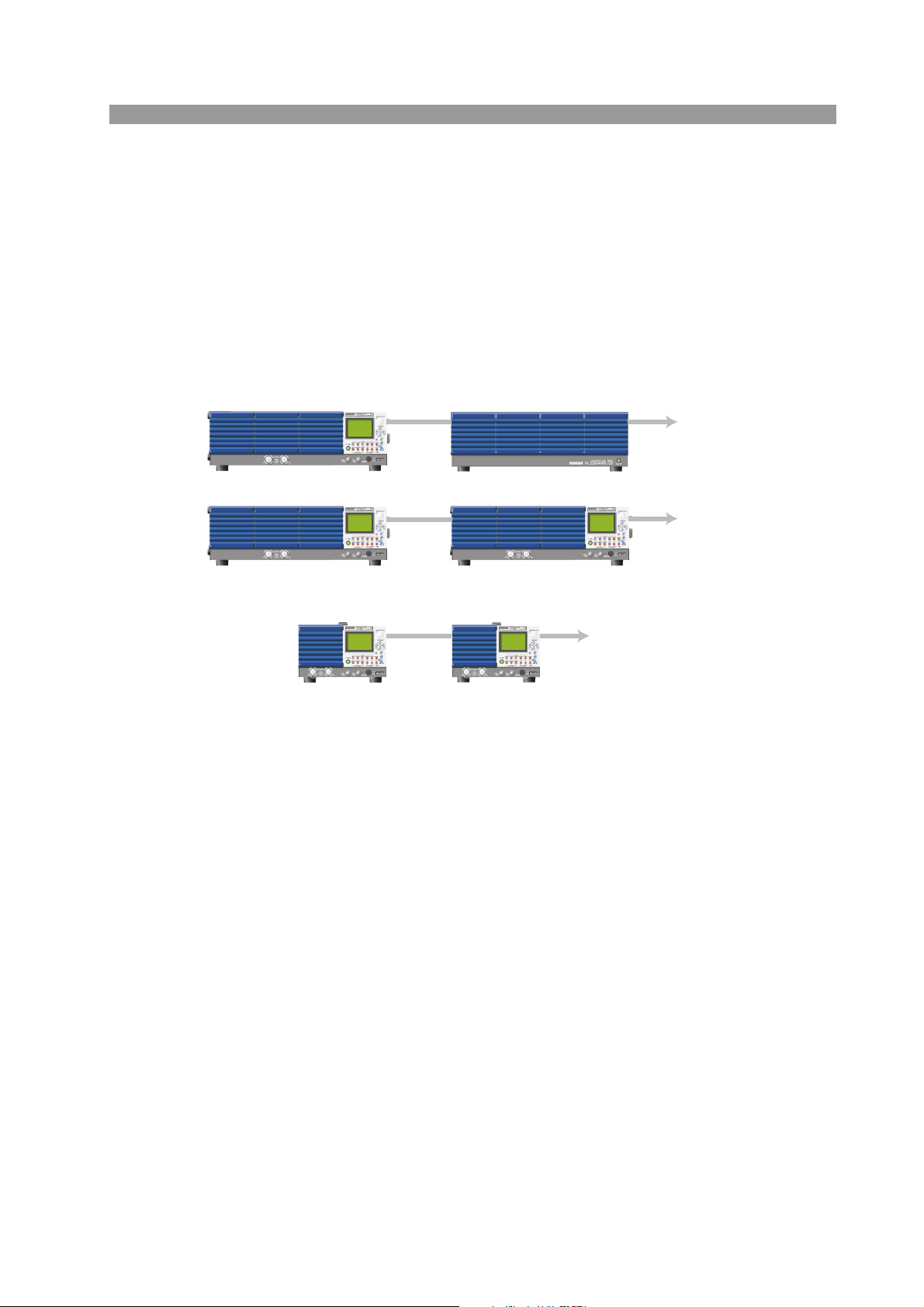
Support for large capacity
Master (PLZ1004W)
Master (PLZ1004W)
Master Slave
Load booster (PLZ2004WB)
Slave (PLZ1004W)
Up to four PLZ2004WBs
can be connected
Up to five PLZ-4Ws of the same type as
the master device can be connected
PLZ-4W other than PLZ1004W
PLZ1004W
Up to five PLZ1004Ws
can be connected
( )
To achieve large capacity at low cost, the PLZ1004W comes with a load booster
(PLZ2004WB).
Using a single PLZ1004W as a master unit, up to four load boosters can be connected in parallel (9 kW, 1 800 A maximum).
In parallel operation without using load boosters, up to five electonic loads of the
same type including the master unit can be connected in parallel (5 kW, 1000 A
maximum).
Fig. 1-3 Parallel connection
PLZ-4W General Information 1-7
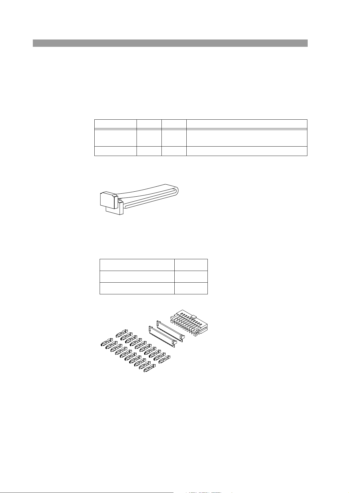
1.6 Options
Control flat cables
Control cable used to connect between the master unit and the slave unit (load
booster) and between slave units. The following two types of cables are available.
Model Code Length Application
PC01-PLZ-4W 84540 300 mm
PC02-PLZ-4W 84550 550 mm Connect between the master unit and load booster
The two types of cables only differ in their length. The 550-mm PC02-PLZ-4W is
required to connect the master unit and the load booster.
Analog remote contorol connector kit (OP01-PLZ-4W)
Connect between
unit (load booster) and between slave units
the master unit and the slave
A kit for connecting to the J1/J2 connector.
Pins 20 pcs.
Socket 1 pc.
Protection cover 1 set
1-8 General Information PLZ-4W
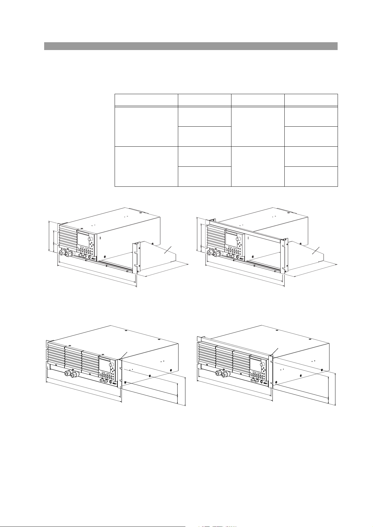
Rack Mounting Option
KRA3
KRA150
132.5 (5.22)
57 (2.24)
37.75 (1.49)
149
100
24.5
465 (18.31)
482 (18.98)
460
480
KRB3-TOS
KRB150-TOS
149
100
24.5
460
479
132 (5.20)
57
(2.24)
37.5
(1.48)
465 (18.31)
479 (18.86)
The following rack mounting options are available.
Item Model Applicable Model Note
Rack adapter
KRA3
(Fig. 1-4)
KRA150
PLZ164W
PLZ334W
PLZ164WA
KRB3-TOS
Rack mount bracket
(Fig. 1-5)
PLZ664WA
PLZ1004W
KRB150-TOS
For details, contact your Kikusui agent or distributor.
Inch rack
EIA standard
Milli rack
JIS standard
Inch rack
EIA standard
Milli rack
JIS standard
Unit: mm (inch)
Fig. 1-4 Rack adapter
Unit: mm (inch)
Fig. 1-5 Rack mount bracket
PLZ-4W General Information 1-9

1-10 General Information PLZ-4W

Chapter 2 Installation and
2
2
Preparation
This chapter describes the procedures of unpacking and preparation before using the
PLZ-4W.
PLZ-4W Installation and Preparation 2-1
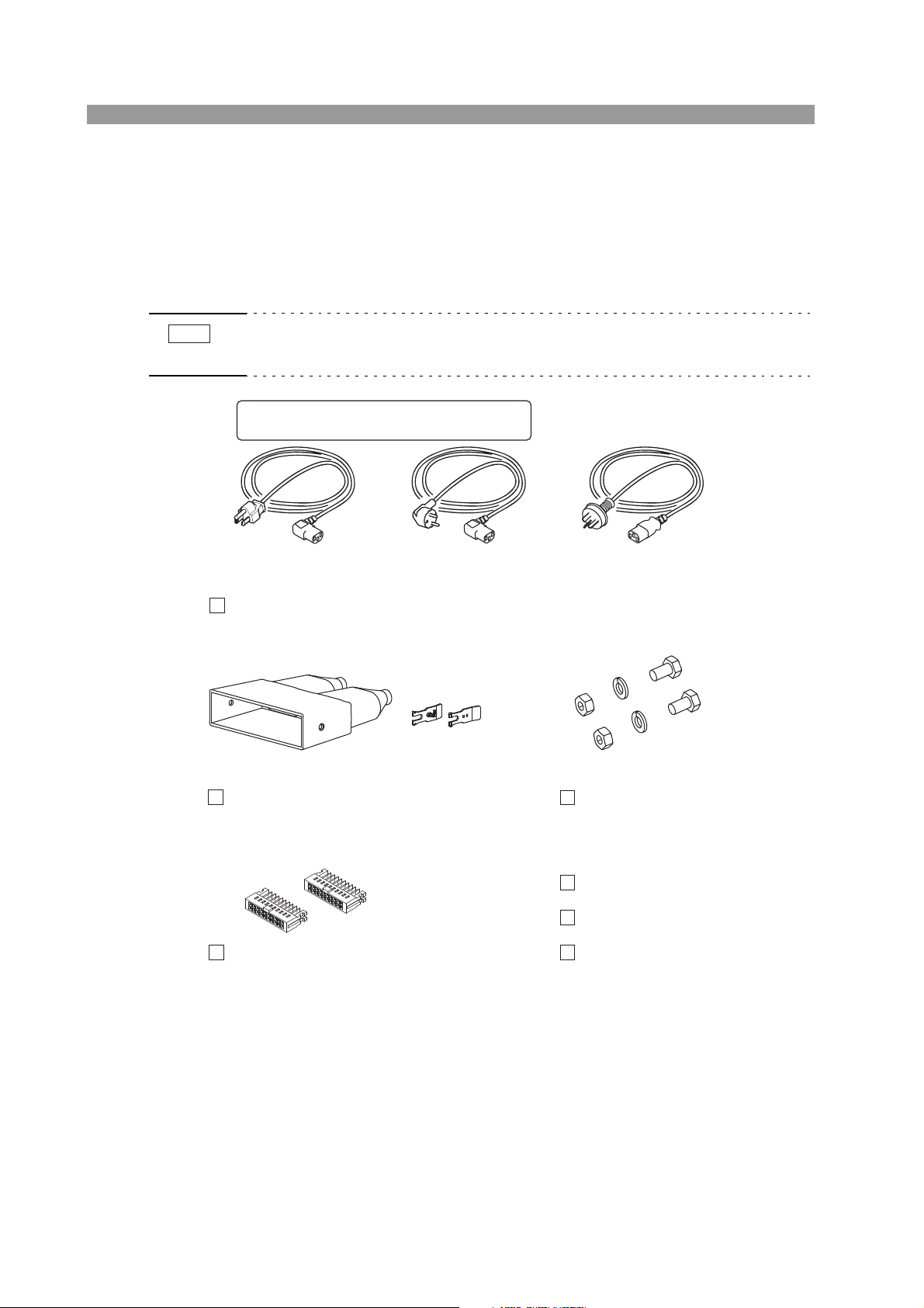
2.1 Checking the Package Contents
NOTE
Load input terminal cover (1 pc.)
Lock plate (2 pcs.)
J1/J2 protection dummy plug (2 pcs.)
[Attached to the product.]
Set of screws for the load input
terminal (2 sets)
Power cord
(1 pc.)
[Q1-500-085]
[P2-000-228]
[M1-100-012]
[M5-101-007]
[M4-100-007]
[84-49-0071]
or or
Setup Guide (1 pc.)
Quick Reference
(Japanese 1sheet, English 1sheet)
CD-ROM (1 pc.)
Plug: NEMA5-15
Rating: 125 Vac/10A
[85-AA-0003]
Plug: CEE7/7
Rating: 250 Vac/10A
[85-AA-0005]
Plug: GB1002
Rating: 250 Vac/10A
[85-10-0790]
The power cord that is provided varies depending on the
destination for the product at the factory-shipment.
When you receive the product, check that all accessories are included and that the
product and accessories have not been damaged during transportation.
If any of the accessories are damaged or missing, contact your Kikusui agent or distributor.
• It is recommended that all packing materials be saved, in case the product needs to
be transported at a later date.
Fig.2-1 Accessories
2-2 Installation and Preparation PLZ-4W

2.2 Precautions Concerning Installation Location
This section describes the precautions to be taken when installing the unit. Make
sure to observe them.
■ Do not use the unit in a flammable atmosphere.
To prevent the possibility of explosion or fire, do not use the unit near alcohol, thinner or other combustible materials, or in an atmosphere containing such vapors.
■ Avoid locations where the unit is exposed to high temperature
or direct sunlight.
Do not place the unit near a heater or in areas subject to drastic temperature
changes.
Operating temperature range: 0 C to +40 C (+32 F to +104 F)
Storage temperature range: -25 C to +70 C ( -13 F to +158 F)
■ Avoid humid environments.
Do not place the unit in high-humidity locations--near a boiler, humidifier, or water
supply.
Operating humidity range: 20 % to 85 % RH (no condensation)
Storage humidity range: 0 % to 90 % RH (no condensation)
Condensation may occur even within the operating humidity range. In such case, do
not use the unit until the condensation dries up completely.
■ Do not place the unit in a corrosive atmosphere.
Do not install the unit in a corrosive atmosphere or in environments containing sulfuric acid mist, etc. This may cause corrosion of various conductors and bad contacts of connectors inside the unit leading to malfunction and failure, or in the worst
case, a fire.
However, operation in such environments may be possible through alteration. If you
wish to use the unit in such environments, consult your Kikusui agent or distributor.
■ Do not place the unit in a dusty location.
Accumulation of dust can lead to electric shock or fire.
■ Do not use the unit where ventilation is poor.
The unit employs a forced air cooling system. Air is taken in from air inlet located
on panels other than the rear panel and exhausted from the air outlet on the rear
panel. Secure adequate space around the unit to prevent the possibility of fire caused
by accumulation of heat.
Allow at least 20 cm of space between the air inlet/outlet and the wall (or obstacles).
Hot air (approximately 20 C higher than the ambient temperature) is exhausted
from the air outlet. Do not place objects that are affected by heat near the air outlet.
PLZ-4W Installation and Preparation 2-3

■ Do not place objects on top of the unit.
Placing objects on top of the unit can cause failures (especially heavy objects).
■ Do not place the unit on an inclined surface or location subject to vibrations.
The unit may fall or tip over causing damages and injuries.
■ Do not use the unit in a location where strong magnetic or
electric fields are nearby or a location where large amount of
distortion and noise is present on the input power line waveform.
The unit may malfunction.
■ Do not use the unit near highly sensitive measuring instruments or transceivers.
The noise generated by the unit may affect them
■ Secure adequate space around the power plug.
Do not insert the power plug to an outlet where accessibility to the plug is poor.
And, do not place objects near the outlet that would result in poor accessibility to
the plug.
2.3 Precautions When Moving the Unit
When moving the unit to the installation location or when transporting the unit, note
the following points.
■ Turn off the POWER switch.
Moving the unit while the power is turned on can cause electric shock or damage to
the unit.
■ Remove all wiring.
Moving the unit with the cables connected can cause wires to break or injuries due
to the unit falling over.
■ Hold the handle.
When lifting the unit, hold the handle on the side or top panel.
■ When transporting the unit, be sure to use the original packing materials.
Otherwise, damage may result from vibrations or from the unit falling during transportation.
2-4 Installation and Preparation PLZ-4W

2.4 Connecting the Power Cord
WARNING
NOTE
The power cord that is provided varies depending on the destination for the product
at the factory-shipment.
• This product is designed to be connected to a power supply classified as
Overvoltage Category II. Do not connect to a power supply classified as
Overvoltage Category III or IV.
• The power cord for 100-V system has a rated voltage of 125 VAC. If this
power cord is used at the line voltage of a 200-V system, replace the
power cord with that satisfying that line voltage.
Have a qualified engineer select the appropriate power cord. If obtaining
the right power cord is difficult, contact Kikusui distributor/agent.
• The power cord with a plug can be used to disconnect the PLZ-4W series from the
AC power line in an emergency. Connect the plug to an easily accessible power
outlet so that the plug can be removed from the outlet at any time. Be sure to provide adequate clearance around the power outlet.
• Do not use the power cord that comes with the product as a power cord for other
equipment.
Check that the AC power supply is within the input power supply range
1.
of the product.
Input voltage range: 100 VAC to 240 VAC
(100 V to 120 V and 200 V to 240 V for the PLZ164WA
and PLZ664WA)
Frequency range: 47 Hz to 63 Hz
2.
Check that the POWER switch is turned off.
3.
Connect the power cord to the AC INPUT connector on the rear panel.
Use a power cord specified by Kikusui or one that has been selected by a qualified engineer.
4.
Insert the power plug to the outlet.
PLZ-4W Installation and Preparation 2-5
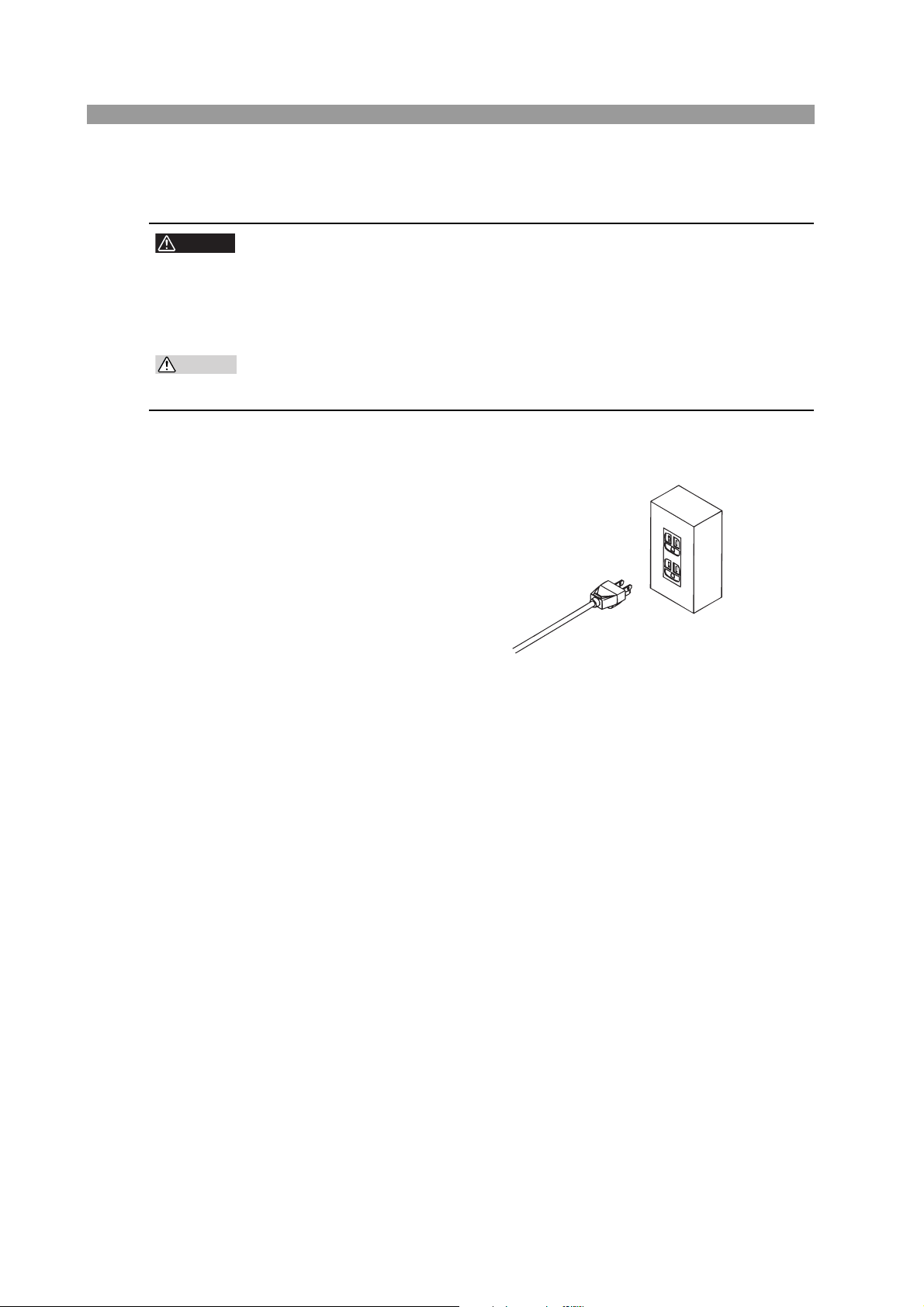
2.5 Grounding (Earth)
WARNING
CAUTION
Three-pin outlet with proper grounding
Fig. 2-2 Grounding
• Electric shock may occur, if proper grounding is not furnished.
• This product is designed as a Class I equipment (equipment furnished with
electric shock protection through protective grounding in addition to the
basic insulation). Be sure to connect the protective ground terminal to an
appropriate earth ground.
• If you do not ground the product, malfunction may occur due to external
noise, or the noise generated by the product may become large.
Make sure to ground the unit for your safety.
Connect the power cord to a three-pin power outlet with proper grounding.
2-6 Installation and Preparation PLZ-4W
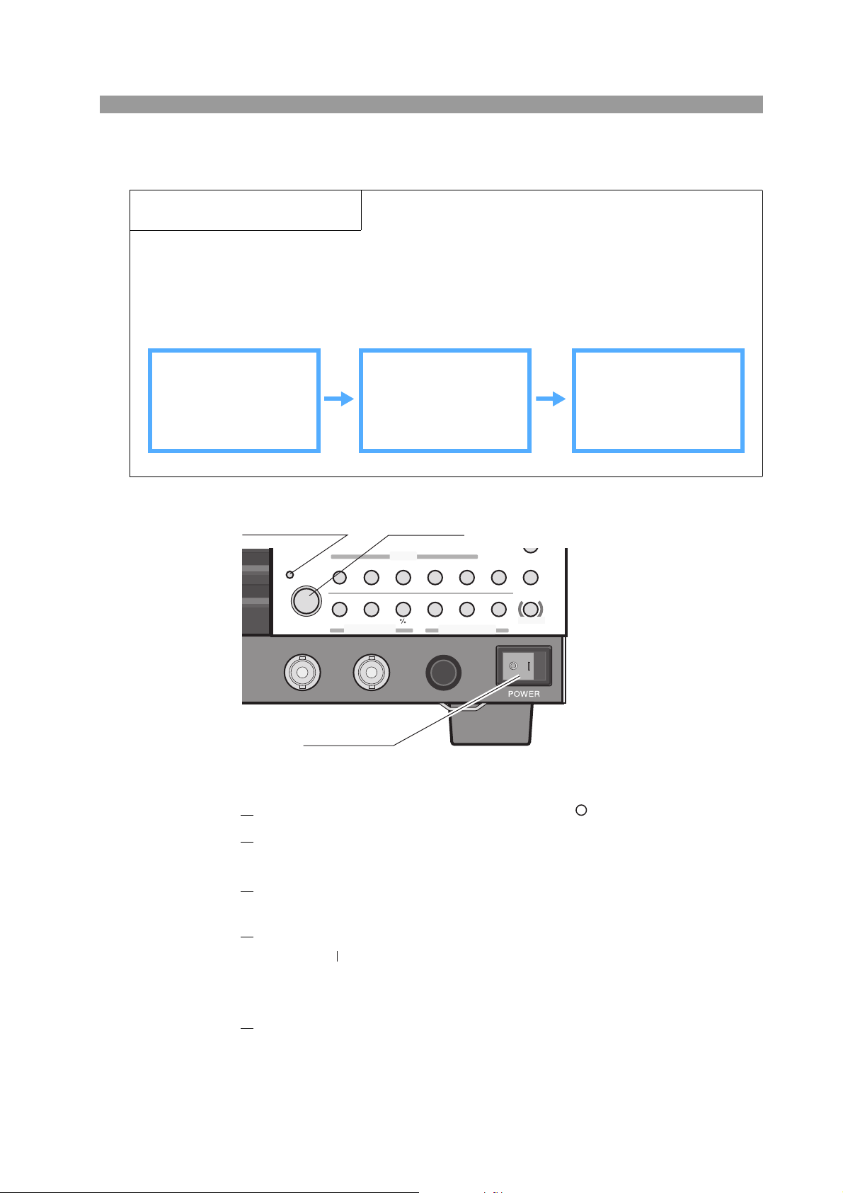
2.6 Turning on The Power
SWITCHING
ENTER
SHORT
EDIT
SLEW RATE
RUN /STOP
UVP
PAUS E
STORE
RECALL
ABC
LOAD
Th/TL
FREQ /DUTY
MENU
PRESET
SEQ
I
LEVEL
VRANGE
RANGE
SW ON
+
CV
MODE
LOAD
SET/VSET
LOCK
SHIFT
ABC
OPP /OCP
POWER
REMOTE
I MON
OUTOUT
TRIG
POWER switch
LOAD key
Load on indication
LED
Overview of the procedure
Carry out this procedure without connecting anything to the DC INPUT (load input terminal).
Turn on the POWER switch and then operate the LOAD key.
At the end, turn off the POWER switch.
If an alarm occurs during operation, see section 5.3, “Types of Protection Functions.
Preparation Main operation Unit behavior
Do not connect anything
to the load input terminal.
Turn on the POWER
switch. Press the LOAD
key.
The display section is
activated.
LOAD indication LED
illuminates.
”
PLZ-4W Installation and Preparation 2-7
Fig. 2-3
1.
2.
3.
4.
5.
Check that the POWER switch is turned off( ).
Check that the power cord is correctly connected.
See section 2.4, “Connecting the Power Cord” and 2.5, “Grounding (Earth).”
Check that nothing is connected to the DC INPUT (load input terminal)
on the front and rear panels.
Turn the POWER switch on.
Push the ( ) side of the POWER switch to turn the PLZ-4W on.
A self-test is executed. A special screen appears during the test at startup. A
normal display appears when the self-test is complete.
Check whether the display appears as shown in Fig. 2-4.
The measured value displayed using large numbers (section with mA, V, and
W unit) indicates coarse zero.
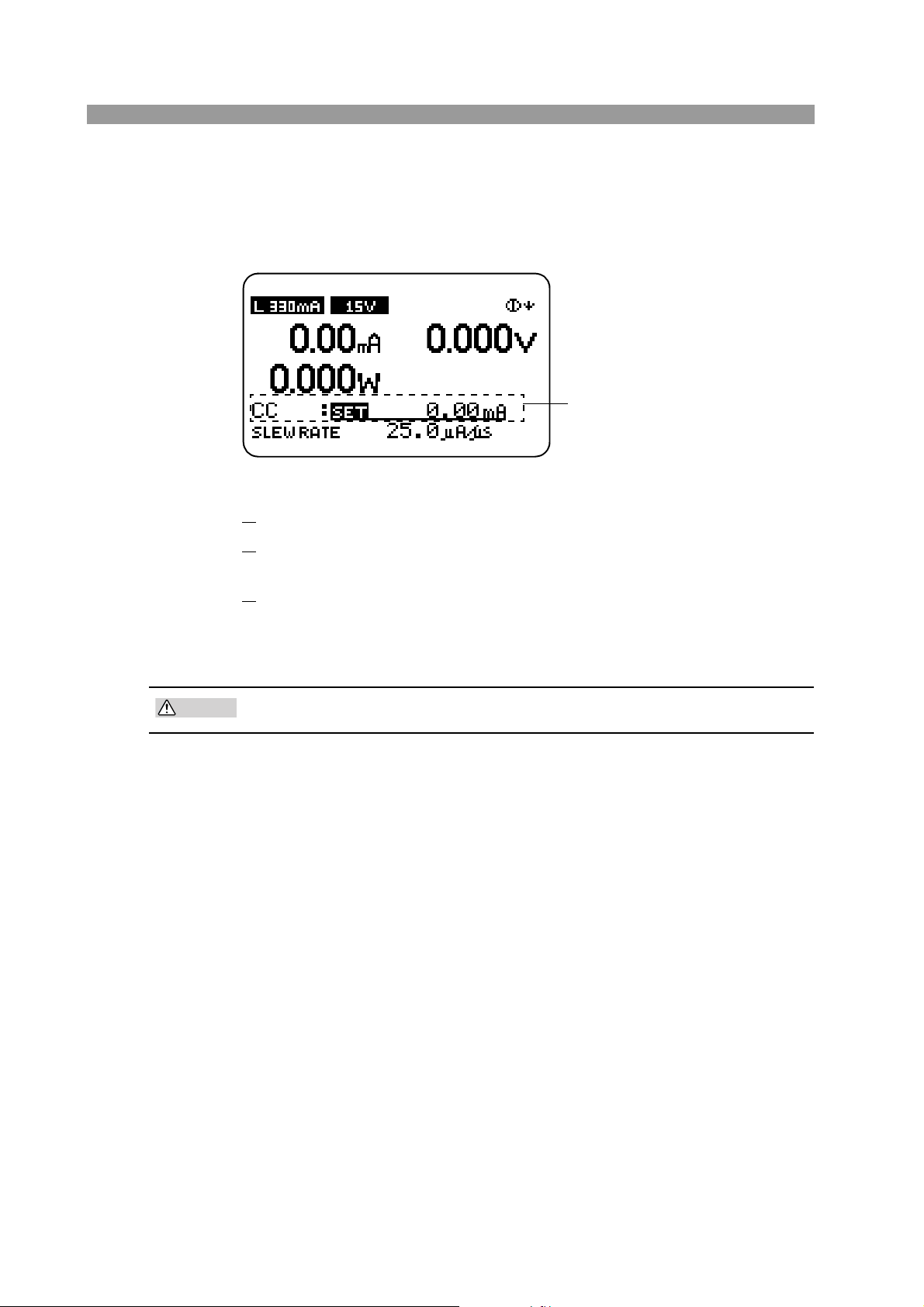
The characters “SET” shown under the measured value is highlighted with an
Constant current (CC) mode is
selected on this screen. Therefore, current can be entered.
CAUTION
underline.
This indicates that basic settings can be entered in the selected operation mode.
This condition in which characters “SET” is highlighted is called the basic set-
ting entry condition.
Fig. 2-4 Basic setting entry condition
6. Press the LOAD key and check that the LED above the key illuminates.
7.
Press the LOAD key again and check that the LED above the key turns
off.
8.
Turn off the POWER switch to finish the operation check procedure.
The PLZ-4W saves the last setup conditions through the backup function even
when the power is turned off. When the power is turned on the next time, the
PLZ-4W returns to the conditions that were backed up.
• To prevent malfunction, allow at least 5 s between power cycles.
If the PLZ-4W does not operate as described in the procedure
If one of the following conditions applies to your case, carry out the corresponding
procedure. If the condition does not change even after taking the countermeasure
indicated below, contact Kikusui distributor/agent.
Nothing is displayed.
Check the power cord connection and power cycle the unit.
Adjust the display contrast. For the adjustment procedure, see the next page.
Indicates an abnormal current or voltage.
Power cycle the unit.
An alarm occurs.
See section 5.3, “Types of Protection Functions.”
2-8 Installation and Preparation PLZ-4W
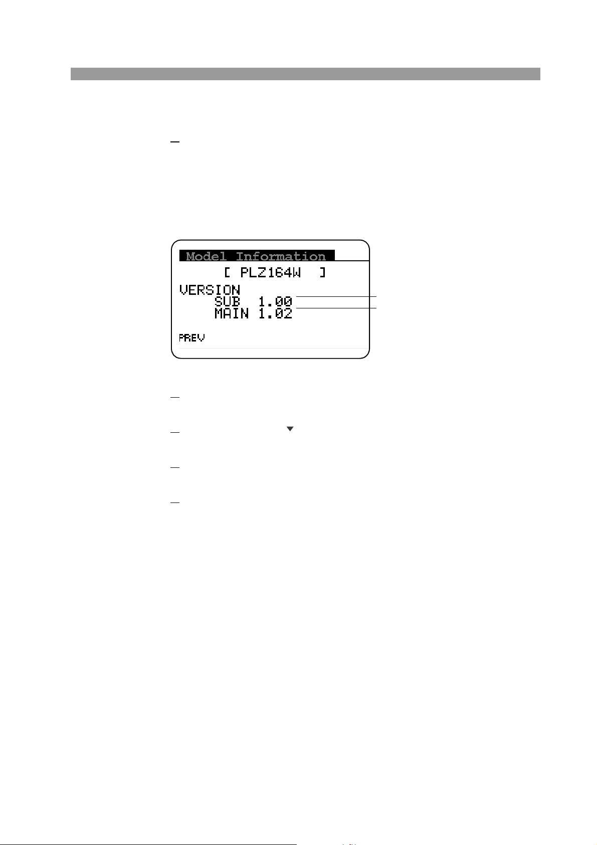
Adjusting the display contrast
Firmware Version
ROM Version
1. While pressing the SHIFT key, use the rotary knob to adjust the con-
trast.
The result is saved.
2.7 Checking the ROM Version
Fig. 2-5 Model Information screen (PLZ164W)
Press the MENU (SHIFT+SET/VSET) key.
1.
The menu screen is displayed.
2.
Use the CURSOR key to select 4. Model Info.
The selected section is highlighted.
3.
Press the ENTER key.
The Model Information screen of Fig. 2-5 is displayed.
4.
Press the MENU (SHIFT+SET/VSET) key to close the menu.
PLZ-4W Installation and Preparation 2-9
2.8 Load Wiring
NOTE
CAUTION
To ensure that the functions of the PLZ-4W work accurately and reliably, all wires
must be connected correctly to their loads.
• This operation manual refers to the terminal on the rear panel to which the equip-
ment under test is connected and current is supplied as load input terminal.
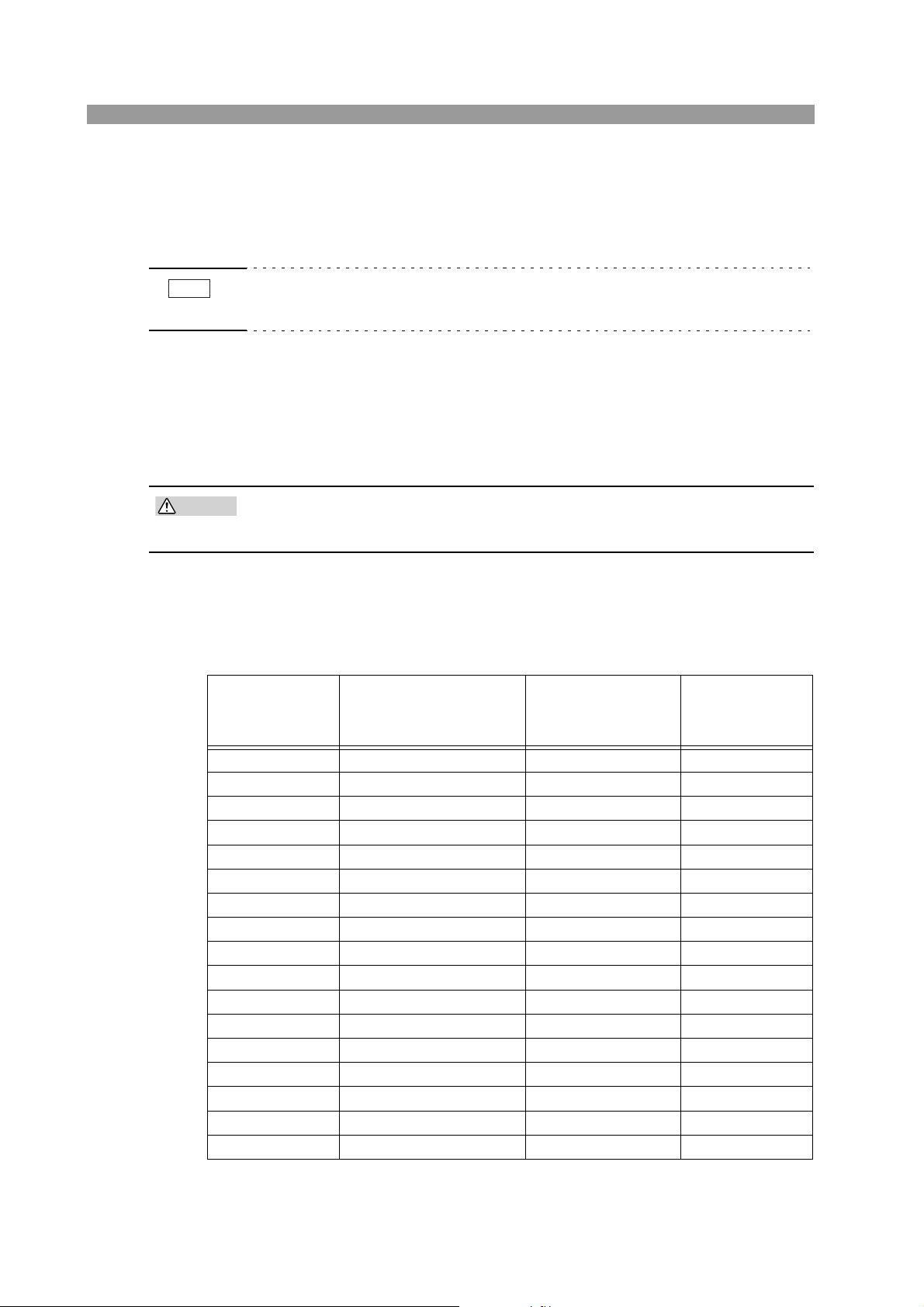
2.8.1 Precautions Concerning Wiring
Electric wire used
• Use a load wire with sufficient diameter for the current as well as non-flam-
mable or flame-resistant cover.
If the resistance of the load wire is large, a large voltage drop may occur when a current is supplied and the voltage at the load input terminal may fall below the minimum
operating voltage. Refer to Table 2-1 and select thick wires as much as possible.
Table2-1 Nominal cross-sectional area of wires and allowable currents
Nominal Cross-
Sectional Area
2
]
[mm
2 14 (2.08) 27 10
3.5 12 (3.31) 37 -
5.5 10 (5.26) 49 20
8 8 (8.37) 61 30
14 6 (13.3) 88 50
22 4 (21.15) 115 80
30 2 (33.62) 139 -
38 1 (42.41) 162 100
50 1/0 (53.49) 190 -
60 2/0 (67.43) 217 -
80 3/0 (85.01) 257 200
100 4/0 (107.2) 298 -
125 - - 344 -
150 - - 395 300
200 - - 469 -
250 - - 556 -
325 - - 650 -
*Excerpts from Japanese laws related to electrical equipment.
AW G
(Reference Cross-
Sectional Area)
2
]
[mm
Allowable Current(*)
[A]
(Ta = 30 C)
Kikusui-Recom-
mended Current
[A]
2-10 Installation and Preparation PLZ-4W
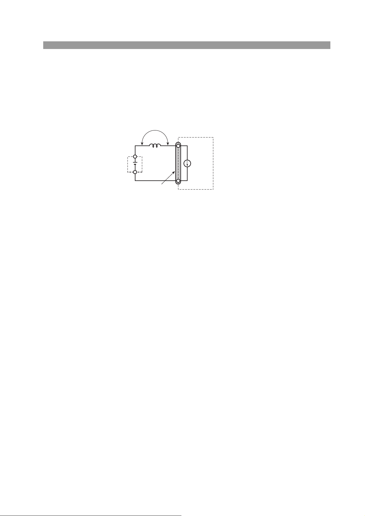
Load wire inductance
EUT
PLZ-4W
L
I
ΔI/ΔT
E
E = Lx (ΔI/ΔT)
Load input terminal
+
-
The load wiring has an inductance (L). When the current (I) varies in short time
period, it generates a large voltage at both ends of the wiring cable. This voltage
applies to all of the load input terminals of the PLZ-4W when the impedance of the
EUT is relatively small. The voltage generated by the load wire inductance (L) and
the current varaiation (I) is expressed using the following equation.
Fig. 2-6 Load wire and inductance
In general, the wire inductance can be measured approximately 1 µH per 1 meter. If
the 10 meters of load cables is wired between the EUT and the PLZ-4W with the
current variation of 10 A/µs, the voltage generated by the wire inductance will be
100 V.
The negative polarity of the load input terminal is the reference potential of the
external control signal, therefore, the device connected to the external control terminal may get malfunctioned.
When operating under the constant voltage (CV) mode or constant resistance (CR)
mode or constant power (CP) mode, the load current is varied by the voltage at the
load input terminal, so the operation can be affected easily by the generated voltage.
The wiring to the EUT should be twisted and the shortest as possible.
PLZ-4W Installation and Preparation 2-11
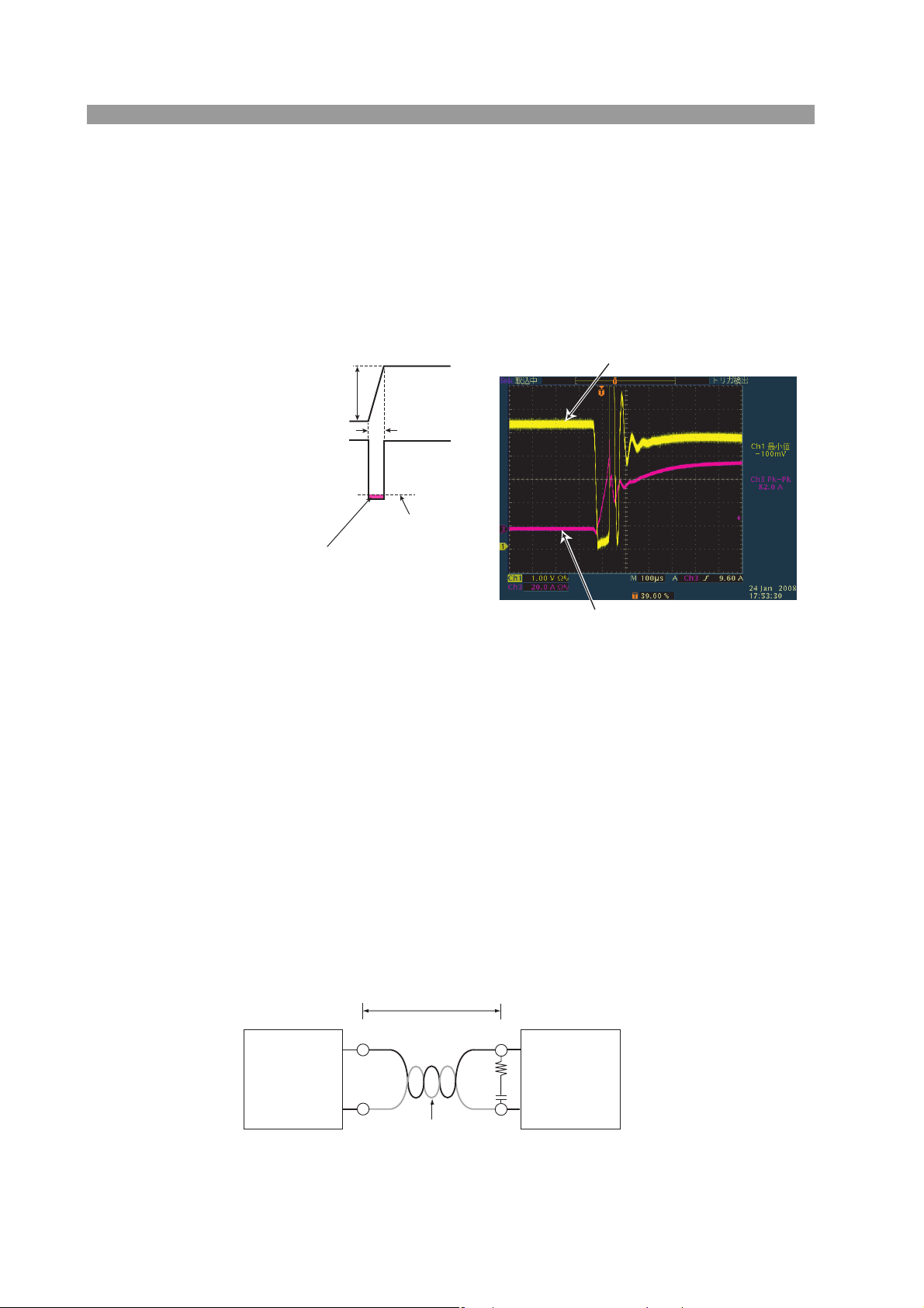
If the load wire is long or has a large loop, the wire inductance is increased. Conse-
Equipment
under test
PLZ-4W Series
Electronic Load
Keep the wire short
100 cm or less
Twi st
–
–
+
+
R
C
Example: R=10 Ω, C=100 μF
quently, the current variation at the time of switching operation will cause a large
voltage drop.
When the value of instantaneous voltage drops under the minimum operating voltage depends on the generated voltage at the load input terminal, the response of
recovery will be extensively delayed. In such event, the PLZ-4W may generate
unstable oscillation or becomes into the hunting operation. In such condition, the
input voltage may exceed the maximum input voltage and cause damage to the PLZ4W.
Voltage at the load input terminal
Current
Voltage at Load
Input Terminal
When the voltage drops under minimum
operating voltage, the electronic load may
generate unstable oscillation or becomes
into hunting operation.
ΔI
ΔT
Minimum operating
voltage
Current
Example of waveform
Fig. 2-7 Waveform example: Generate unstable oscillation or hunting operation
You must be careful especially when the slew rate setting is high or switching is performed using large currents through parallel operation.
To prevent problems, connect the PLZ-4W and the equipment under test using the
shortest twisted wire possible to keep the voltage caused by inductance within the
minimum operating voltage and maximum input voltage range or set a low slew rate.
If the high-speed response operation is not required, set the lower response speed
and decrease the slew rate setting.
In the case of DC operation also, the phase lag of the current may cause instability
in the PLZ-4W control inducing oscillation. In this case also, connect the PLZ-4W
and the equipment under test using the shortest twisted wire possible. If only DC
operation is required, a capacitor and a resistor may be connected to the load input
terminal as shown in Fig. 2-8 to alleviate oscillation. In this case, use the capacitor
within its allowable ripple current.
Fig. 2-8 Length of wiring
2-12 Installation and Preparation PLZ-4W
■ Operation when the response speed is changed
CAUTION
Fig. 2-9 Overvoltage alarm
CAUTION
Equipment
under test
PLZ-4W Series
Electronic Load
DC150 V
+
–
+
–
Fig. 2-11 Reverse connection alarm
You can change the response speed in CC mode (CC+CV mode) and CR mode
(CR+CV mode).
In some cases, the wire inductance increases and the phase lag of the current may
cause instability in the PLZ-4W control inducing oscillation.
In such case, you can decrease the response speed to assure stable operation.
• For a description of response speed, see section 5.15, “Response Speed.”
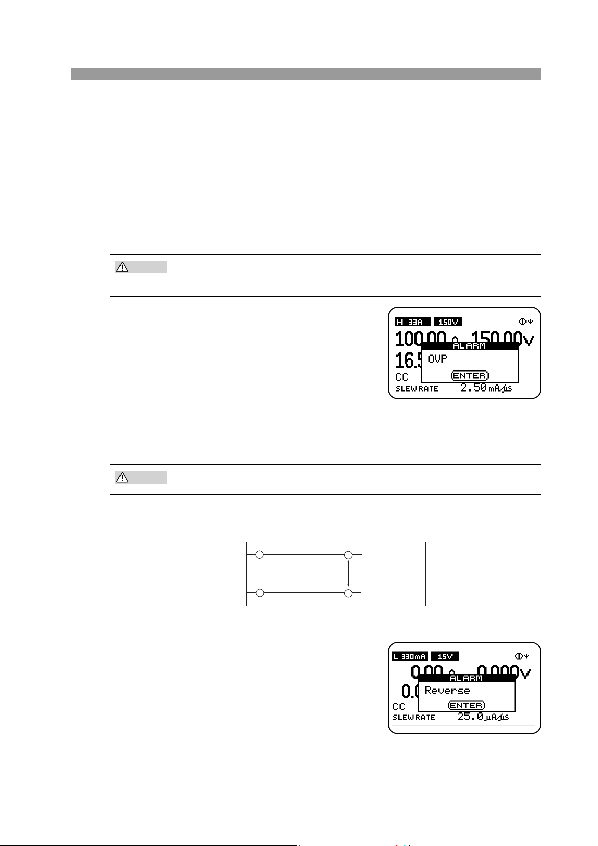
Overvoltage
• Do not apply voltage exceeding the maximum voltage of 150 VDC to the
The maximum voltage that can be applied to
the load input terminal is 150 VDC. Voltage
exceeding the maximum cannot be used.
If overvoltage is applied, an alarm message
appears along with a beeping alarm, and the
load is turned off. In this case, immediately
lower the voltage of the equipment under
test.
load input terminal, as it may cause damage.
Polarity
• If the polarity is reversed, overcurrent may damage the EUT and PLZ-4W.
Be sure to match the polarities between the load input terminal and the equipment
under test.
Fig. 2-10 Connection by paying attention to the polarity
If the polarity is reversed, an alarm
message appears along with a beeping alarm. In this case, turn off the
power of the equipment under test
within 30 seconds after the alarm is
activated. (the beeping alarm sounds
when a reverse voltage of 0.6 V or
greater is applied).
PLZ-4W Installation and Preparation 2-13
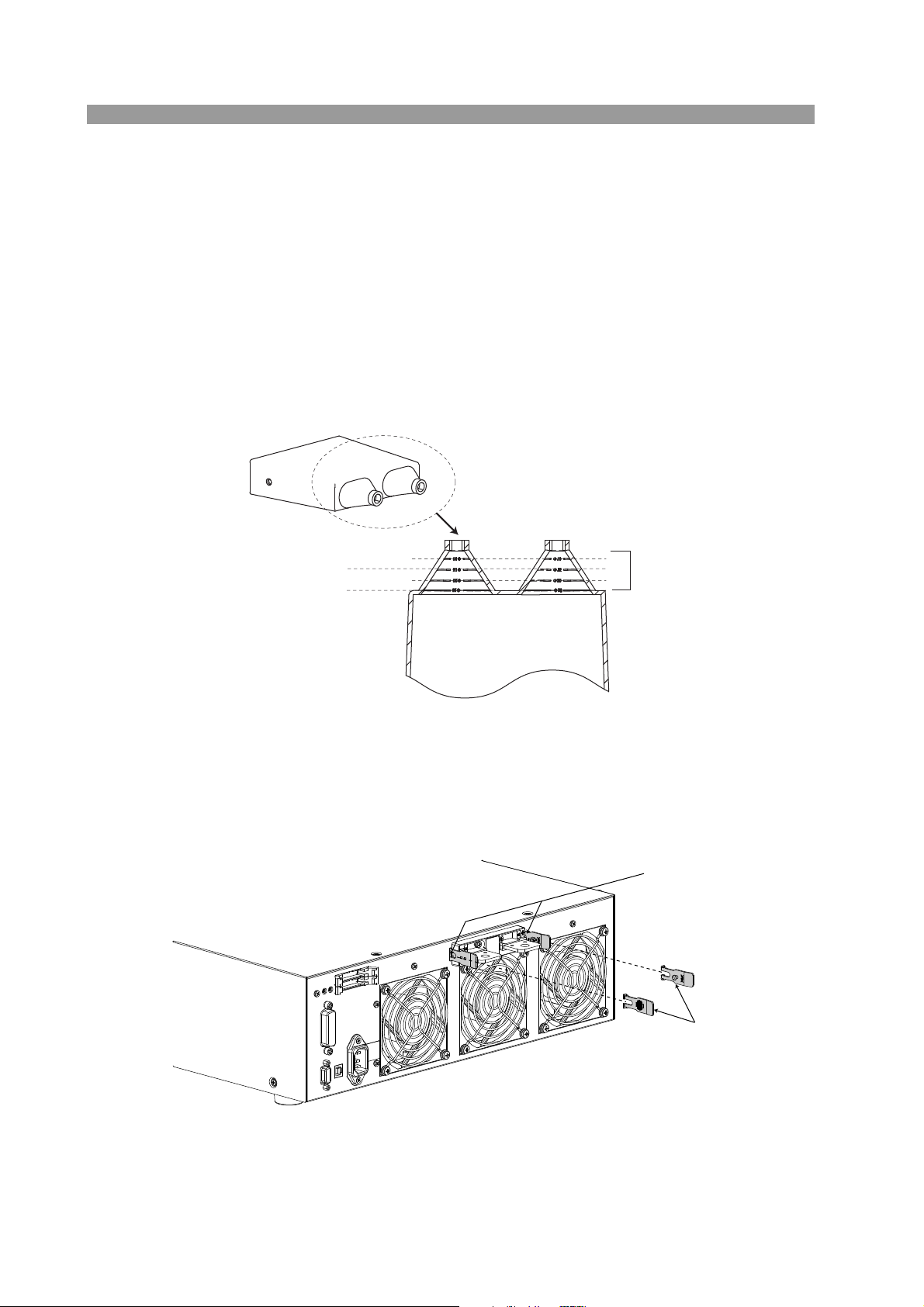
2.8.2 Connection to the Load Input Terminal on the Rear
I10 line
I20 line
I25 line
I15 line
Cut the sleeve to match
the wire diameter by using
the gauge as a reference.
Lock plate
Insert the lock plate to the
groove on the side of the
terminal.
Panel
Using the terminal cover
The load input terminal cover that comes with the package is used by passing
through the load wire.
If the wire that you are using is thick and cannot be passed through the cover sleeve
(where the wire is passed through), cut and adjust the size of the sleeve to match the
thickness of the wire.
Use trial and error so that you don't cut too much of the sleeve.
Fig. 2-12 Load input terminal cover
Attaching the lock plate
The lock plate is used to fix the load input terminal cover to the rear panel.
Once attached, you do not have to remove it. When using the load input terminal
cover for the first time, attach the lock plate in advance.
Fig. 2-13 Attachment of the lock plate
2-14 Installation and Preparation PLZ-4W

Connection procedure of the load input terminal on the rear panel
WARNING
CAUTION
Bolt (M8 x 18)
Spring washer (M8)
Load input terminal
cover
Nut (M8)
Crimp terminal
Be sure to use the
set of screws
provided with the
package.
• Do not touch the load input terminal while the PLZ-4W is turned ON, as it
may lead to electric shock.
In addition, be sure to use the load input terminal cover.
• The load input terminals on the front and rear panels are coupled inside
the PLZ-4W. A voltage applied to one end will appear on the other end.
• Do not connect equipment to the load input terminals on the front and rear
panels simultaneously, as it can cause damage.
• There is a danger of breakdown. Do not connect the equipment under test
to the load input terminal when the load is turned on.
• There is a danger of overheat. Attach crimping terminal to the wire and use
the set of screws that came with the package for connection.
1.
Turn off the POWER switch.
2.
Check that the output of the equipment under test is off.
3.
Connect the load wire to the load input terminal on the rear panel.
Use the load input terminal cover. See Fig. 2-12 on how to use the cover.
For the connection procedure of the load wire, see Fig. 2-14.
4.
Fix the load input terminal cover to the rear panel using the lock plate.
Pass the inner pin of the lock plate through the hole on the side of the cover.
For details, see Fig. 2-15.
5.
Connect the load wire to the output terminal of the equipment under
test.
6.
Check the polarity of the connection.
Fig. 2-14 Connection to the load input terminal on the rear panel
PLZ-4W Installation and Preparation 2-15

Fig. 2-15 Attachment of the load input terminal cover
Move the cover until the edge touches the
panel, and pinch the section indicated by
the arrow to raise the side surface.
With the side surface of the cover
raised, insert the lock plate pin into the
hole.
Top view
Check that the left and right lock plate
pins are securely inserted in the cover
holes.
Removing the load input terminal cover.
Open the lock plate left and right, and remove the pin from the hole of the cover.
2-16 Installation and Preparation PLZ-4W

2.8.3 Connection to the Load Input Terminal on the Front Panel
WARNING
CAUTION
NOTE
Spring washer (M6)
Crimp terminal
Cover
Knob
M6
Attach so that the wire
passes through this section.
The load input terminal on the front panel can be used to easily connect the equipment under test and the PLZ-4W.
• Do not touch the load input terminal while the PLZ-4W is turned ON, as it
may lead to electric shock.
• The load input terminals on the front and rear panels are coupled inside
the PLZ-4W. A voltage applied to one end will appear on the other end.
• Do not connect equipment to the load input terminals on the front and rear
panels simultaneously, as it cause damage.
• There is a danger of breakdown. Do not connect the equipment under test
to the load input terminal when the load is turned on.
• There is a danger of overheat. Attach crimping terminal to the wire and use
the set of screws that came with the package for connection.
• The specifications of the PLZ-4W are for the load input terminal on the rear panel.
• The maximum input current to the load input terminal on the front panel is 66 A.
It is automatically limited to 66 A.
1.
Turn off the POWER switch.
2.
Check that the output of the equipment under test is off.
3.
Connect the load wire to the load input terminal on the front panel.
For the connection procedure of the load wire, see Fig. 2-16.
4.
Connect the load wire to the output terminal of the equipment under test.
5. Check the polarity of the connection.
PLZ-4W Installation and Preparation 2-17
Fig. 2-16 Connection to the load input terminal on the front panel

2-18 Installation and Preparation PLZ-4W

Chapter 3 For First Time Users
3
3
This chapter describes for first time users, the operation modes of the PLZ-4W and
matters that users should be familiar with in operating the PLZ-4W.
PLZ-4W For First Time Users 3-1

3.1 What Is an Electronic Load
SWITCHING
165W
ELECTRONIC LOAD
1.5-150V 0-33A
PLZ164W
ENTER
SHORT
EDIT
SLEW RATE
RUN STOP
UVP
PAUSE
STORE
RECALL
ABC
LOAD
Th/TL
FREQ DUTY
MENU
PRESET
SEQ
I
LEVEL
VRANGE
RANGE
SW ON
+
CV
MODE
LOAD
SET VSET
LOCK
LOCAL
CURSOR
COARSE/FINE
SHIFT
ABC
OPP OCP
PREV
DEL
INS
NEXT
DC INPUT
165W
1.5
-
150V
0
-
33A
REMOTE
I MON
OUTOUT
TRIG
POWER
DC INPUT
165W
1.5
-
150V
0
-
33A
REMOTE
I MON
OUTOUT
TRIG
SWITCHING
1000W
ELECTRONIC LOAD
1.5-150V 0-200A
PLZ1004W
ENTER
SHORT
EDIT
SLEW RATE
RUN STOP
UVP
PAUSE
STORE
RECALL
ABC
LOAD
Th/TL
FREQ DUTY
MENU
PRESET
SEQ
I
LEVEL
VRANGE
RANGE
SW ON
+
CV
MODE
LOAD
SET VSET
LOCK
LOCAL
CURSOR
COARSE/FINE
SHIFT
ABC
OPP OCP
PREV
DEL
INS
NEXT
POWER
When measuring the characteristics of the power supply in designing a power supply, a load that is applied to the power supply is required. An electronic load refers
to a device that uses semiconductors (transistors) in place of a variable resistor to act
as a load. Because voltage and current can be controlled freely on a semiconductor,
the load can be controlled arbitrarily by embedding a control circuit.
The electronic load is used as (1) a load for various electronic circuits, (2) a load for
characteristics tests and life tests of various DC power supplies such as a switching
power supply and primary and secondary batteries, and (3) a load for aging. The
sequence function can be used to simulate the load tests of power supplies with
large load fluctuation (such as a power supply for a printer) in a condition that is
close to the actual load.
Fig.3-1 PLZ164W (1.5 V input type), PLZ164WA (0 V input type), and
PLZ334W (1.5 V input type)
Fig. 3-2 PLZ664WA (0 V input type) and PLZ1004W (1.5 V input type)
3-2 For First Time Users PLZ-4W

3.2 Basic Flow of Operation
This section runs through the precautions concerning installation and preparation,
the use of the operation panel, and functions that are convenient for performing
experiments and tests.
• For details on the precautions concerning installation and preparation, see chap-
ter 2, "Installation and Preparation.”
Preparations before using the PLZ-4W
Precautions to be taken when installing or moving the PLZ-4W
Be sure to read section 2.2, "Precautions Concerning Installation Location” when
installing the PLZ-4W.
When moving the PLZ-4W, be sure to turn off the power and remove the power
cord. When lifting the PLZ-4W, hold the handle on the side or top panel.
• Avoid using the PLZ-4W in a dusty environment, an environment
with poor ventilation, on an inclined surface, a location subject to
vibrations, or a location subject to strong magnetic or electric
fields.
• Do not obstruct the air inlet on the front panel and the air outlet on
the rear panel.
Always ground the PLZ-4W
Be sure to earth ground the PLZ-4W before turning on the power to prevent electric
shock.
Precautions to be taken when connecting the equipment under test
• Be sure to turn off the power when touching the load input terminal
(front and rear panels) or when connecting the load. Be especially
careful of the polarity of the connection between the load input terminal and the equipment under test.
• Use a load wire with sufficient diameter for the current as well as
non-flammable or flame-resistant cover.
• Do not connect equipment under test to the load input terminals on
the front and rear panels simultaneously.
On using the PLZ-4W
Precaution to be taken when turning on the power
Check that there are no irregularities in the input power supply or power cord before
turning on the power. After connecting the power cord, turn on the POWER switch
to turn on the PLZ-4W.
• Allow at least 5 seconds between power cycles.
• If you feel something is wrong with the PLZ-4W, turn off the power
switch. Then, remove the power plug from the outlet or remove the
power cord from the PLZ-4W.
PLZ-4W For First Time Users 3-3

Warming up the PLZ-4W
CAUTION
0.00mA 0.000
V
0.000
W
0.000 A
0.01
mA/μs
SET
33A 150V
Fine
adjustment
V
A
Coarse
adjustment
NOTE
To perform stable measurements, allow the PLZ-4W to warm up for at least 30 minutes before starting tests. While the PLZ-4W is warming up, check the operation of
the PLZ-4W and the connection of the equipment under test.
Voltage drop in the load wire
If the load wire is long, a voltage drop occurs due to the resistance of the cable. If
the amount of voltage drop caused by the wire cannot be ignored or if you wish to
set the resistance, voltage, and current accurately, execute remote sensing before
making measurements. For the setup procedure of the remote sensing function, see
section 6.7, "Remote Sensing Function.”
How to use the operation panel
The PLZ-4W is controlled from the operation panel on the front panel. If you make
an invalid selection or perform an invalid key operation, a beep is sounded to notify
the error. In particular, please familiarize yourself with the use of the SHIFT key
that changes the key function.
• For a description of the functions of each key, see chapter 4, "Names and Func-
tions of Parts.”
• To prevent the possibility of electric shock, never touch the load
input terminal while the equipment under test is connected and the
power is turned on. When touching the load input terminal, be sure
to turn off the equipment under test.
■ Function of the LOAD key
If you press the LOAD key when the load is turned off, the LOAD LED illuminates,
and the load turns on. If you press the LOAD key when the load is turned on, the
LOAD LED turns off, and the load turns off.
• There is a danger of breakdown. Turn off the load when applying the out-
put of the equipment under test to the PLZ-4W. Then, turn the load on. If
you are making the connection with the load turned on, be sure to turn off
the output of the equipment under test.
If a relay or electromagnetic switch is inserted between the load input terminal and the output terminal of the equipment under test, turn on the
relay or electromagnetic switch when the load is turned off. Then, turn the
load on.
■ How to use the rotary knob
The rotary knob is used when setting values such as the current and resistance.
Turning the rotary knob to the right increases the value and turning it to the left
decreases the value. In addition, you can press the rotary knob to switch between
coarse adjustment and fine adjustment. When the “” shown at the upper right corner of the screen is large, coarse adjustment is active; when it is small, fine adjustment is active. When setting a value, use coarse adjustment to set the value roughly,
and then switch to fine adjustment to set value precisely.
3-4 For First Time Users PLZ-4W
• You can traverse the full scale of values by turning the rotary knob ten and a few
turns. Fine adjustment changes values at 1/10 of the rate of coarse adjustment.

■ Pop-up menu operation
0.00mA0.000
V
0.000
W
CC
SLEWRATE
0.000
A
0.01
mA/μs
SET
H 33A 150V
CP
CC
CR
CV
Pop-up menu
Some keys show a pop-up menu when you press the key. If you press the key again
while the menu is shown, the selected item switches. Each time you press the key,
the selected item switches one by one to the next item. When you finish the key
operation, the item at that point is selected, and the pop-up menu automatically
clears.
■ How to use the SHIFT key
The SHIFT key is used to switch the function of each key. If you press a key without
holding down the SHIFT key, the function indicated above the key is enabled; if you
press a key while holding down the SHIFT key, the function indicated below the key
is enabled.
For example, if you press the SET/VSET key without holding down the SHIFT key,
the SET/VSET (indicated in black) function is enabled. If you press the SET/VSET
key while holding down the SHIFT key, the MENU (indicated in blue) is enabled.
This manual denotes the operation of holding down a key while holding down the
SHIFT key as SHIFT+(notation above the key). For example, when selecting the
MENU key, this manual denotes it as MENU (SHIFT+SET/VSET). In this case,
press the SET/VSET key while holding down the SHIFT key.
Saving the setup conditions
You can use the memory function to save the settings that you are using. The ABC
preset memories can save three separate sets of settings of each range of each operation mode. The setup memory can save 100 sets of the current setup condition and
the contents of the ABC preset memories in that condition. The information saved to
the memory is backed up even when the power is turned off (the information is
saved until the PLZ-4W is initialized).
• For a description of the ABC preset memories, see section 6.1, "ABC preset
memories.” For a description of the setup memory, see section 6.2, "Setup Memory.”
• For a description of initialization, see section 5.14, "Initialization.”
Performing waveform simulation
The sequence function is used to perform waveform simulation. The sequence function automatically executes the time change of the waveform specified arbitrarily
one operation at a time. The program information that you create is backed up even
when the power is turned off.
• For a description of the sequence function, see section 6.6, "Sequence Func-
tion.”
Maintenance and transportation after use
Before performing maintenance work, be sure to turn off the power and remove the
power plug from the outlet or the power cord from the PLZ-4W.
• For details on maintenance, see chapter 8, "Maintenance and Calibration.”
• If the PLZ-4W requires repairs or readjustment, do not open the
outer cover by yourself. Contact your Kikusui agent.
• When transporting the PLZ-4W, remove the power cord and cables,
and use the original packing materials.
PLZ-4W For First Time Users 3-5

3.3 Operating area of the PLZ-4W
0.1
1
10
100
0.1 1 10
Input current [A]
Input voltage [V]
Actual operating area
165 W
150
5
1.5
0.3
1.1
33
Logarithmic
scale
Operating area where
specifications are
guaranteed
L1
L2
L3
L5
L4
L5
0
0.5
0.3
1
010
Input current [A]
Input voltage [V]
Operating area where
specifications are
guaranteed
33
1.5
2.0
1.3
20
30
Actual operating area
L3
L4
Low voltage area
Low voltage area
<1.5 V
Logarithmic
scale
0.1
0.3
1
10
100
0.1 1 10
Input current [A]
Input voltage [V]
Operating area where
specifications are
guaranteed
165 W
150
5
1.1
33
L1
L2
L3
L4
0
0.5
0.3
1
010
Input current [A]
Input voltage [V]
Operating area where
specifications are
guaranteed
33
1.5
2.0
20
30
L3
Low voltage area
As shown in Fig. 3-3, the PLZ-4W can be used within the area enclosed by the constant voltage line according to the rated voltage (L1), the constant power line
according to the rated power (L2), the constant current line according to the rated
current (L3), and the constant voltage line according to the minimum operating voltage (L4) (operating area where specifications are guaranteed). For PLZ-4Ws with
the minimum operating voltage of 0 V, the specifications are guaranteed at input
voltages at 0 V and greater. For 1.5 V input types, the specifications are guaranteed
at input voltages of 1.5 V and greater. If the current is decreased, these types can be
used even at voltages lower than 1.5 V. However, the specifications are not guaranteed. (Actual operating area)
Minimum voltage at which the current starts flowing to the PLZ-4W is approximately 0.3 V.
The PLZ-4W detects no signal at an input voltage less than or equal to approximately 0.3 V and an input current less than or equal to approximately 1 % of the
range rating. If the input voltage is gradually increased from 0 V, no current will
flow until 0.3 V is exceeded. Once a current greater than or equal to 1 % of the
range rating (When PLZ-4W is set by the M range: greater than or equal to 1 % of H
range) starts flowing, the current can flow at voltages less than equal to 0.3 V.
If the minimum operating voltage (L5) in the actual operating area is reached, the
operating status on the display indicates C.R using outline characters (see section
4.4, "Display”).
PLZ164W
(1.5 V input type)
H range
PLZ164WA
(0 V input type)
H range
Fig. 3-3 Operating area
3-6 For First Time Users PLZ-4W

3.4 Basic Operation Modes
The following six operation modes are available on the PLZ-4W.
1. Constant current mode (CC mode)
2. Constant resistance mode (CR mode)
3. Constant power mode (CP mode)
4. Constant voltage mode (CV mode)
5. Constant current and constant voltage mode (CC+CV mode)
6. Constant resistance and constant voltage mode (CR+CV mode)
Below is a description of the most basic CC mode. For a detailed description, see
appendix A.2, "Basic Operation Modes.”
3.4.1 Operation of the CC Mode
In CC mode, the current is kept constant even when the voltage changes.
■ CC mode operation
When the PLZ-4W is used in CC mode, the PLZ-4W operates as a constant current
load as shown in Fig. 3-4. The PLZ-4W sinks the specified current (I) independent
of the output voltage of the constant-voltage power supply (V1).
R1
Constant-voltage
power supply
V1
I
V
PLZ-4W Series
Electronic Load
Voltage [V]
0
Current is constant
even when the voltage
changes
Current [A]
CCsettingvalue
Fig. 3-4 Equivalent circuit of the constant current load and operation
■ Transition of the operating point
We will consider the case when checking the load characteristics of the constantvoltage power supply of Fig. 3-4 using CC mode.
PLZ-4W For First Time Users 3-7

Fig. 3-5 Transition of the operating point in CC mode (OPP trip point)
Input current [A]
Input voltage [V]
Logarithmic
scale
A
B
C
(OPP setting)
Constant power line
Operating area
OPP trip point
D
V1
V2
NOTE
Fig. 3-5: Operation on segment AB
If the voltage of the constant-voltage power supply is set to V1 and the input current
(load current) of the PLZ-4W is increased, the operating point moves along segment
AB.
When point B is reached, overpower protection (OPP) trips. At this point, two types
of operation are available on the PLZ-4W depending on the protection action setting
of the OPP.
If the protection action is set to LOAD OFF, an alarm screen indicating OPP
appears, and the load turns off.
If protection action is set to LIMIT, the operating status indicates OPP, and the PLZ4W sinks current as a constant power load at point B. Even if you attempt to
increase the input current, the current is limited at point B. If you decrease the input
current, the OPP is cleared, and the operating status indicates C.C. The PLZ-4W
returns to CC mode, and the operating point moves along segment AB.
Table3-1 OPP action (protect action)
3-8 For First Time Users PLZ-4W
Fig. 3-5: Operation on segment CD
If the voltage of the constant-voltage power supply is set to V2 and the input current
(load current) of the PLZ-4W is increased, the operating point moves along segment
CD. Point D is the maximum current at the range being used.
• The OPP action (protection action) and the OPP value are set in advance. For a
description of the action setting, see section 5.13, "Menu Setup.” For a description
of the OPP value setting, see section 5.4, "Setting the Protection Function.” For a
description of the operating status indication, see section 4.4, "Display.”
Point B
LOAD OFF
LIMIT
Turns off the load (stops the current flow).
The PLZ-4W no longer operates as a load.
CC mode ends. OPP continues, and the PLZ-4W
sinks current as a constant power load.

3.4.2 Let's Use CC Mode
SWITCHING
165W
ELECTRONIC LOAD
1.5-150V 0-33A
PLZ164W
ENTER
SHORT
EDIT
SLEW RATE
RUN STOP
UVP
PAUS E
STORE
RECALL
ABC
LOAD
Th/TL
FREQ DUTY
MENU
PRESET
SEQ
I
LEVEL
VRANGE
RANGE
SW ON
+
CV
MODE
LOAD
SET VSET
LOCK
LOCAL
CURSOR
COARSE/FINE
SHIFT
ABC
OPP OCP
PREV
DEL
INS
NEXT
REMOTE
I MON
OUTOUT
TRIG
SWITCHING
165W
ELECTRONIC LOAD
1.5-150V 0-33A
PLZ164W
ENTER
SHORT
EDIT
SLEW RATE
RUN STOP
UVP
PAUS E
STORE
RECALL
ABC
LOAD
Th/TL
FREQ DUTY
MENU
PRESET
SEQ
I
LEVEL
VRANGE
RANGE
SW ON
+
CV
MODE
LOAD
SET/ VSET
LOCK
LOCAL
CURSOR
COARSE/FINE
SHIFT
ABC
OPP/ OCP
PREV
DEL
INS
NEXT
POWER switch
LOAD key
RANGE/VRANGE key
MODE key
Rotary knob
OPP/OCP
key
SET/VSET
key
NOTE
This section describes the procedure of setting the operation mode to CC and turning on the load. Below is the flow of the operating procedure. Please familiarize
yourself with the keys used in this procedure.
■ Operating procedure and operation panel
1) Turn on the power and check that the load is turned off.
2) Set the operation mode, range, current value, and the OPP value.
3) Turn on the load.
4) Change the current value.
5) Turn the load off.
Fig. 3-6 Keys used in CC mode
■ Explanation of the operation
1. Turn on the power.
Push the ( ) side of the POWER switch to turn on the power to the PLZ-4W.
Check that the LOAD LED is turned off. If the LED is illuminated, press the
LOAD key to turn off the load.
• When the load is turned ON, you cannot switch the operation mode and range.
PLZ-4W For First Time Users 3-9

2. Select CC mode.
0.00mA0.000
V
0.000
W
CC
SLEWRATE
0.000
A
0.01
mA/μs
SET
H 33A 150V
CP
CC
CR
CV
0.00mA0.000
V
0.000
W
CC
SLEWRATE
1.000
A
0.01
mA/μs
SET
H 33A 150V
LM0.33A
3.3A
33A
H
0.00mA0.000V
0.000W
CC
0.000
A
SET
H 33A 150V
181.5
W
OPP
Press the MODE key to show the operation mode pop-up menu.
If CC is not highlighted, press the MODE key repetitively until CC is high-
lighted.
When the pop-up menu closes, check that CC appears on the display.
3.
Select the current range.
Press the RANGE key to show the current range pop-up menu.
Each time you press the RANGE key while the menu is displayed, the current
range switches in the order L (LOW), M (MIDDLE), and H (HIGH). When the
desired range is highlighted, stop pressing the key.
Along with L, M, or H, the full scale value of the respective range is displayed.
This value varies depending on the model.
4.
Select the voltage range.
Press the VRANGE (SHIFT+RANGE) key to show the voltage range pop-up
menu.
Each time you press the VRANGE key while the menu is displayed, the voltage range switches between 15 V and 150 V. When the desired range is highlighted, stop pressing the key.
5.
Set the current value.
Press the SET/VSET key to illuminate the SET/VSET key.
While viewing the display, turn the rotary knob.
You can press the rotary knob to switch between coarse adjustment and fine
adjustment. First, use coarse adjustment to roughly set the value, and then
switch to fine adjustment to adjust the value precisely.
6.
Set the OPP value.
Press the OPP/OCP key to illuminate the OPP/OCP key and show the OPP
value on the display.
While viewing the display, turn the rotary knob.
You can press the rotary knob to switch between coarse adjustment and fine
adjustment. First, use coarse adjustment to roughly set the value, and then
switch to fine adjustment to adjust the value precisely.
7.
Turn on the load.
Press the LOAD key to illuminate the LOAD LED and allow the current to
flow.
At this point, the display shows the measured values (current, voltage, and
power) at the load input terminal.
8.
Change the current setting.
Turn the rotary knob while the load is turned on to change the current setting.
However, the current value cannot be set greater than the maximum value of
the selected range.
9.
Turn off the load.
Press the LOAD key to turn off the LOAD LED.
3-10 For First Time Users PLZ-4W

Chapter 4 Names and
4
4
Functions of Parts
This chapter describes the names and functions of switches, connectors, and displays on the front panel and rear panel.
PLZ-4W Names and Functions of Parts 4-1

4.1 Front Panel
WARNING
CAUTION
SWITCHING
165W
ELECTRONIC LOAD
1.5-150V 0-33A
PLZ164W
ENTER
SHORT
EDIT
SLEW RATE
RUN /STOP
UVP
PAUS E
STORE
RECALL
ABC
LOAD
Th/TL
FREQ /DUTY
MENU
PRESET
SEQ
I
LEVEL
VRANGE
RANGE
SW ON
+
CV
MODE
LOAD
SET /VSET
LOCK
LOCAL
CURSOR
COARSE/FINE
SHIFT
ABC
OPP /OCP
PREV
DEL
INS
NEXT
DC INPUT
165W
1.5
-
150V
0
-
33A
REMOTE
I MON
OUTOUT
TRIG
[1] DC INPUT
[5] I MON OUT
[6] TRIG OUT
[7] REMOTE
[4] POWER
[2] Air intake [3] Handle
• Do not touch the load input terminal while the PLZ-4W is turned ON, as it
may lead to electric shock.
In addition, be sure to use the load input terminal cover.
• The load input terminals on the front and rear panels are coupled inside
the PLZ-4W. A voltage applied to one end will appear on the other end.
• Do not connect equipment to the load input terminals on the front and rear
panels simultaneously, as it cause damage.
• Avoid using the PLZ-4W in a dusty environment or an environment with
poor ventilation.
• Do not obstruct the air intake on the front panel and the air outlet on the
rear panel.
4-2 Names and Functions of Parts PLZ-4W
Fig.4-1 Front panel (PLZ164W)

[1] DC INPUT (load input terminal on the front panel)
NOTE
The terminal on the front panel that can be used to easily connect the equipment
under test and the PLZ-4W. The load input terminal is also available on the rear
panel, and is connected in parallel with the load input terminal on the front panel.
• For the connection procedure, see section 2.8.3, “Connection to the Load Input
Terminal on the Front Panel.”
• The specifications of the PLZ-4W are for the load input terminal on the rear panel.
The load input terminal on the front panel may not satisfy the specifications.
• The maximum input current to the load input terminal on the front panel is 66 A.
It is automatically limited to 66 A.
[2] Air intake (louver)
Takes in air to cool the inside of the PLZ-4W.
A dust filter is furnished on the inside. Clean the dust filter periodically.
• For details, see section 8.1.2, “Cleaning the Dust Filter.”
[3] Handle
Used to lift the PLZ-4W. The handle is provided on the side panel on the
PLZ1004W and the PLZ664WA. It is provided on the top panel on other models.
[4] POWER switch
Power switch of the PLZ-4W. Push ( ) to turn on, push ( ) to turn off.
Turn the POWER switch on while holding down the ENTER key initializes the
panel settings to factory default.
• For a description of turning on the power, see section 2.6, “Turning on The
Power.”
• For a description of initial settings, see section 5.14, “Initialization.”
[5] I MON OUT connector
Output connector used to monitor the current. Connect a voltmeter or oscilloscope
to monitor the current.
• For details, see section 6.9, “Monitor Signal Output.”
[6] TRIG OUT connector
Outputs pulse signals during sequence operation or switching operation.
• For details, see section 6.9, “Monitor Signal Output.”
[7] REMOTE connector
Connector for future functional expansion.
PLZ-4W Names and Functions of Parts 4-3

4.2 Rear Panel
WARNING
CAUTION
AC INPUT
100-240V
47
-
63Hz
160VA MAX
KCC-REM-KEJ
-
PLZ-78270
2012/05
AC INPUT
100-240V
47
-
63Hz
160VA MAX
[1] DC INPUT
[4] Remote sensing terminal
[7] RS232C
[6] GPIB
[8] USB
[3] AC INPUT
[5] Manufacturing number
[2] Air outlet
[9] J1/J2
[10] EXT CONT
• Do not touch the load input terminal while the PLZ-4W is turned ON, as it
may lead to electric shock.
In addition, be sure to use the load input terminal cover.
• The load input terminals on the front and rear panels are coupled inside
the PLZ-4W. A voltage applied to one end will appear on the other end.
• Do not connect equipment to the load input terminals on the front and rear
panels simultaneously, as it cause damage.
• Avoid using the PLZ-4W in a dusty environment or an environment with
poor ventilation.
• Do not obstruct the air intake on the front panel and air exhaust on the rear
panel with objects. In particular, allow at least 20 cm of space behind the
PLZ-4W.
Fig. 4-2 Rear panel (PLZ164W)
4-4 Names and Functions of Parts PLZ-4W

[1] DC INPUT (load input terminal on the rear panel)
Terminal used to connect the equipment under test to the PLZ-4W. It is connected in
parallel with the load input terminal on the front panel.
• For the connection procedure, see section 2.8.2, “Connection to the Load Input
Terminal on the Rear Panel.”
[2] Air outlet
Exhausts the internal air using the cooling fan to cool the inside of the PLZ-4W.
[3] AC INPUT connector
Connector used to connect the power cord.
• For a description of the connection, see section 2.4, “Connecting the Power
Cord.”
[4] Remote sensing terminal
Terminal used to connect the sensing wires when correcting the voltage drop caused
by the resistance of the load wire.
• For details, see section 6.7, “Remote Sensing Function.”
[5] Manufacturing number (serial No.)
Manufacturing number of the PLZ-4W.
[6] GPIB connector
Connector used to connect the GPIB cable when controlling the PLZ-4W externally.
• For a description of the interface setup, see section 7.2.1, “GPIB Control.”
[7] RS232C connector
Connector used to connect the RS232C cable when controlling the PLZ-4W externally.
• For a description of the interface setup, see section 7.2.2, “RS232C Control.”
[8] USB connector
Connector used to connect the USB cable when controlling the PLZ-4W externally.
• For a description of the interface setup, see section 7.2.3, “USB Control.”
[9] J1/J2 connector
Input/Output connector used to control the PLZ-4W externally using external voltage, resistance, relay contact, etc.
J1 is assigned to external control; J2 is assigned to parallel operation.
• For details on external control and the connector, see section 6.8.1, “Overview
and Precaution of External Control.”
[10] EXT CONT
Variable resistor used to adjust the full scale and offset settings of the PLZ-4W with
respect to the input value of the external control source (voltage or resistance).
PLZ-4W Names and Functions of Parts 4-5

4.3 Operation Panel
SWITCHING
165W
ELECTRONIC LOAD
1.5-150V 0-33A
PL Z164W
ENTER
SHORT
EDIT
SLEW RATE
RUN STOP
UVP
PAUSE
STORE
RECALL
ABC
LOAD
Th/TL
FREQ DUTY
MENU
PRESET
SEQ
I
LEVEL
VRANGE
RANGE
SW ON
+
CV
MODE
LOAD
SET VSET
LOCK
LOCAL
CURSOR
COARSE/FINE
SHIFT
ABC
OPP OCP
PREV
DEL
INS
NEXT
[1] LOAD
[5] SHIFT
[4] LOCAL/LOCK
[3] CURSOR
[2] Rotary knob
S
T
If you press a key while holding down the SHIFT key, the function indicated below
the key is enabled.
R
R
IN
PREV
DE
NEX
Fig. 4-3 Operation Panel
[1] LOAD key
The current that flows through the PLZ-4W is turned on and off each time you press
the key. When the load is turned on, the LED illuminates (green).
[2] Rotary knob
The rotary knob is used to set various types of values on the PLZ-4W. By pressing
the rotary knob you can switch between coarse adjustment and fine adjustment.
COARSE/FINE
When set to coarse adjustment, “ ” appears on the screen. You can traverse the full
scale of values by turning the rotary knob ten and a few turns When set to fine
adjustment, “ ” appears. The value changes at 1/10 of the rate of coarse adjustment.
Contrast
You can change the display contract by turning the rotary knob while holding down
the SHIFT key.
[3] CURSOR key
Moves the cursor up and down or right and left when selecting an item on the menu
4-6 Names and Functions of Parts PLZ-4W
screen.

INS/DEL/PREV/NEXT
SWITCHING
ENTER
SHORT
EDIT
SLEW RATE
RUN / STOP
UVP
PAUSE
STORE
RECALL
ABC
LOAD
Th/TL
FREQ /DUTY
MENU
PRESET
SEQ
I
LEVEL
VRANGE
RANGE
SW ON
+
CV
MODE
LOAD
SET / VSET
LOCK
SHIFT
ABC
OPP /OCP
[10] OPP OCP/UVP
[9] SLEW RATE/SHORT
[8] RANGE/VRANGE
[7] SET VSET/MENU
[6] MODE/+CV
P
GE
T/VS
T
Operate the keys while holding down the SHIFT key to turn pages (PREV/NEXT)
on the menu screen or insert (INS) or delete (DEL) steps of the sequence function.
[4] LOCAL/LOCK key
LOCAL
Switches to panel control (local control) when the PLZ-4W is being controlled
remotely.
LOCK
Pressing this key while holding down the SHIFT key (SHIFT+LOCAL) locks the
PLZ-4W. Pressing the LOCK (SHIFT+LOCAL) key while the PLZ-4W is locked
releases the lock. When releasing the lock, keep holding the key until a beep is
heard.
• For details, see section 5.11, “Lock Function.”
[5] SHIFT key
Switches the function of each key. If you press a key without holding down the
SHIFT key, the function indicated above the key is enabled; if you press a key while
holding down the SHIFT key, the function indicated below the key is enabled.
[LOAD]
V
MENUVRAN
HORTV
Fig. 4-4 Operation panel (LOAD)
[6] MODE/+CV key
MODE
Pressing this key when the load is turned off switches the operation mode.
Press the MODE key to show the operation mode pop-up menu. Each time you
press the MODE key while the menu is displayed, the operation mode switches in
the order CC, CR, CV, and CP.
When in switching mode (SW ON key is illuminated) or CC+CV or CR+CV mode,
you cannot select the CV and CP operation modes on the pop-up menu. You cannot
select the operation mode when the short function is enabled.
PLZ-4W Names and Functions of Parts 4-7

+CV
Pressing this key while holding down the SHIFT key (SHIFT+MODE) adds constant voltage mode (+CV) to CC mode or CR mode.
When in CC mode, this operation switches the mode to CC+CV; when in CR mode,
this operation switches the mode to CR+CV. The current mode is indicated on the
display.
[7] SET/VSET/MENU key
SET/VSET
Enters the basic setting (current, conductance, voltage, or power). This key illuminates when you can change the basic setting.
In CC+CV mode, current and voltage are selected alternately each time you press
the key. In CR+CV mode, conductance and voltage are selected alternately each
time you press the key.
MENU
Pressing this key while holding down the SHIFT key (SHIFT+SET VSET) shows the
menu setup screen for setting the functions of the PLZ-4W and changing the settings.
• For details, see section 5.13, “Menu Setup.”
[8] RANGE/VRANGE key
RANGE
Switches the current, conductance, or voltage range according to the operation
mode.
Pressing the RANGE key when the load is turned off shows the range pop-up menu.
Each time you press the RANGE key while the menu is displayed, the range
switches in the order L, M, and H. You cannot select the range when the load is
turned on or when the short function is enabled.
VRANGE
Pressing this key while holding down the SHIFT key (SHIFT+RANGE) switches
the voltage range.
Pressing the VRANGE (SHIFT+RANGE) key when the load is turned off shows the
range pop-up menu. Each time you press the VRANGE (SHIFT+RANGE) key while
the menu is displayed, the range switches in the order 15 V and 150 V. You cannot
select the range when the load is turned on or when the short function is enabled.
[9] SLEW RATE/SHORT key
SLEW RATE
Sets the slew rate value. This key illuminates when you can change the slew rate.
You cannot select the slew rate in CV or CP mode.
• For details, see section 6.4, “Setting the Slew Rate.”
SHORT
Pressing this key while holding down the SHIFT key (SHIFT+SLEW RATE) sets or
clears the short function. A short icon is displayed while the short function is
enabled. You cannot select the short function in switching, CV, or CP mode.
• For details, see section 5.12, “Short Function.”
4-8 Names and Functions of Parts PLZ-4W

[10] OPP/OCP/UVP key
SWITCHING
ENTER
SHORT
EDIT
SLEW RATE
RUN / STOP
UVP
PAUSE
STORE
RECALL
ABC
LOAD
Th/TL
FREQ /DUTY
MENU
PRESET
SEQ
I
LEVEL
VRANGE
RANGE
SW ON
+
CV
MODE
LOAD
SET / VSET
LOCK
SHIFT
ABC
OPP /OCP
[11] SW ON
[12] FREQ DUTY/Th
/
TL
[13] LEVEL/%
Th/TL
N
OPP/OCP
Sets the voltage for tripping the overpower protection (OPP) or the current for tripping the overcurrent protection (OCP). This key illuminates when you can set the
OPP or OCP.
• For details, see section 5.4, “Setting the Protection Function.”
UVP
Pressing this key while holding down the SHIFT key (SHIFT+OPP/OCP) enables
you to set the voltage for tripping the undervoltage protection (UVP).
• For details, see section 5.4, “Setting the Protection Function.”
[SWITCHING]
SW O
Q/
Fig. 4-5 Operation panel (SWITCHING)
[11] SW ON key
Turns on or off the switching mode. The switching mode is valid in CC mode or CR
mode. The SW ON key illuminates in switching mode. You cannot select switching
mode when the short function is enabled.
• For details, see section 6.3, “Switching Function.”
[12] FREQ/DUTY/Th/TL key
FREQ/DUTY
Sets the switching frequency and duty cycle in switching operation. This key illuminates when you can set the switching frequency or duty cycle. FREQ and DUTY
settings switch each time you press the key.
Th/TL
Pressing this key while holding down the SHIFT key (SHIFT+FREQ DUTY)
enables you to set the switching time (Th: High side, TL: Low side) in switching
operation. This key illuminates when you can change the switching time. Th and TL
settings switch each time you press the key. You cannot select the switching time in
CV or CP mode.
PLZ-4W Names and Functions of Parts 4-9

[13] LEVEL/% key
SWITCHING
ENTER
SHORT
EDIT
SLEW RATE
RUN / STOP
UVP
PAUSE
STORE
RECALL
ABC
LOAD
Th/TL
FREQ /DUTY
MENU
PRESET
SEQ
I
LEVEL
VRANGE
RANGE
SW ON
+
CV
MODE
LOAD
SET / VSET
LOCK
SHIFT
ABC
OPP /OCP
[16] A/EDIT
[17] B/RUN STOP
[18] C/PAUSE
[15] ENTER
[14] RECALL/STORE
/
A
C
LEVEL
Sets the switching level in switching operation. This key illuminates when you can
change the switching level.
%
Pressing this key while holding down the SHIFT key (SHIFT+LEVEL) enables you
to set the switching level in terms of a percentage (0.0 % to 100.0 %) of the current
setting. This key illuminates when you can change the switching level. You cannot
select the switching level in CV or CP mode.
[PRESET/SEQ]
TORE
AB
N
Fig. 4-6 Operation panel (PRESET/SEQ)
[14] RECALL/STORE key
RECALL
Recalls the panel settings saved to the setup memory. You cannot select this key
when the load is turned on.
• For details, see section 6.2, “Setup Memory.”
STORE
Pressing this key while holding down the SHIFT key (SHIFT+RECALL) saves the
current panel settings to the setup memory.
4-10 Names and Functions of Parts PLZ-4W

[15] ENTER/ABC key
ENTER
Confirms various types of values during menu setup.
• Pressing the ENTER key when an alarm is activated resets the alarm. However,
the alarm will be activated again if you do not correct the cause of the alarm.
ABC
Pressing this key while holding down the SHIFT key (SHIFT+ENTER) saves the
current settings to the ABC preset memories.
• For details, see section 6.1, “ABC preset memories.”
[16] A/EDIT key
A
Use this key to recall the settings stored in memory A or save the current settings to
memory A.
EDIT
Pressing this key while holding down the SHIFT key (SHIFT+A) shows the
sequence edit screen.
• For details, see section 6.6, “Sequence Function.”
[17] B/RUN/STOP key
B
Use this key to recall the settings stored in memory B or save the current settings to
memory B.
RUN/STOP
Pressing this key while holding down the SHIFT key (SHIFT+B) shows the
sequence execution screen. Pressing RUN/STOP (SHIFT+B) when sequence operation is being executed aborts the operation.
[18] C/PAUSE key
C
Use this key to recall the settings stored in memory C or save the current settings to
memory C.
PAUSE
Pressing this key while holding down the SHIFT key (SHIFT+C) pauses the
sequence being executed. Pressing the PAUSE (SHIFT+C) key when the operation
is paused resumes the sequence.
PLZ-4W Names and Functions of Parts 4-11

4.4 Display
0.00mA 0.000V
0.000W
CC
SLEWRATE
0:06:23
0.000
A
0.01
mA/μs
SET
H 33A 150V
R
C . C
[1] Range display [2] Status display
[3] Measured value display
[5] Elapsed time display
[7] Basic setting display
[8] Multi display
[4] Operation status display
[6] Operation mode display
33A
00
A
00
00
You can change the display contract by turning the rotary knob while holding down
the SHIFT key. The contrast setting is backed up even when the power is turned off.
Fig. 4-7 Display
[1] Range display
Displays the current and voltage range.
.
.
LEWRATE
m
.
[2] Status display
Displays (from the left) the lock, remote, and rotary knob coarse/fine adjustment
status.
[3] Measured value display
Displays the measured values of current (A), voltage (V), and wattage (W).
[4] Operation status display
Displays the current operation mode when the load is turned on.
[5] Elapsed time display
Displays the elapsed time since the load was turned on.
By factory default, the elapsed time display (Count Time) is turned off (not shown).
To show the elapsed time, turn it on from the menu settings. You can also automatically turn off the load after a specified time elapses after the load is turned on (Cut
Off).
• For details of menu setup, see section 5.13, “Menu Setup.”
[6] Operation mode display
Displays the specified operation mode.
[7] Setup display
4-12 Names and Functions of Parts PLZ-4W
Displays the basic setting in the specified operation mode.
[8] Multi display
Displays various settings and current status according to the condition.

Chapter 5 Basic Operation
5
5
This chapter describes the operating procedure of each operation mode and other
basic functions.
PLZ-4W Basic Operation 5-1

5.1 Panel Control Basics
0.00mA0.000
V
0.000
W
CC
SLEWRATE
0.000 A
0.01
mA/μs
SET
H 33A 150V
Fine
adjustment
0.000
V
A
mA/μs
Coarse
adjustment
NOTE
0.00mA0.000
V
0.000
W
CC
SLEWRATE
0.000 A
0.01
mA/μs
SET
H 33A 150V
CP
CC
CR
CV
Pop-up menu
The PLZ-4W is controlled from the operation panel on the front panel. If you make
an invalid selection or perform an invalid key operation, a beep is sounded to notify
the error. In particular, please familiarize yourself with the use of the SHIFT key
that changes the key function.
• For a description of the functions of each key, see chapter 4, “Names and Functions of Parts.”
■ Function of the LOAD key
If you press the LOAD key when the load is turned off, the LOAD LED illuminates,
and the load turns on. If you press the LOAD key when the load is turned on, the
LOAD LED turns off, and the load turns off.
■ How to use the rotary knob
The rotary knob is used when setting values such as the current and resistance.
Turning the rotary knob to the right increases the value and turning it to the left
decreases the value. In addition, you can press the rotary knob to switch between
coarse adjustment and fine adjustment. When the shown at the upper right corner
of the screen is large, coarse adjustment is active; when it is small, fine adjustment is
active. When setting a value, use coarse adjustment to set the value roughly, and
then switch to fine adjustment to set value precisely.
• Fine adjustment changes values at 1/10 of the rate of coarse adjustment. When
you turn the rotary knob while pressing the LOCAL key in the coarse adjustment,
you can set the value more roughly.
■ Pop-up menu operation
Some keys show a pop-up menu when you press the keys. If you press the key again
while the menu is shown, the selected item switches. Each time you press the key,
the selected item switches one by one to the next item. When you finish the key
operation, the item at that point is selected, and the pop-up menu automatically
clears.
■ How to use the SHIFT key
The SHIFT key is used to switch the function of each key. If you press a key without
holding down the SHIFT key, the function indicated above the key is enabled; if you
press a key while holding down the SHIFT key, the function indicated below the key
is enabled.
For example, if you press the SET/VSET key without holding down the SHIFT key,
the SET/VSET (indicated in black) function is enabled. If you press the SET/VSET
key while holding down the SHIFT key, the MENU (indicated in blue) is enabled.
This manual denotes the operation of pressing a key while holding down the SHIFT
key as SHIFT + (notation above the key). For example, when selecting the MENU
key, this manual denotes it as MENU (SHIFT + SET/VSET). In this case, press the
SET/VSET key while holding down the SHIFT key.
5-2 Basic Operation PLZ-4W

5.2 Turning On or Off the Load
CAUTION
“Turning on the load” refers to the operation of supplying current to the PLZ-4W.
“Turning off the load” refers to the operation of cutting off the current to the PLZ4W. The LOAD key is used to turn on or off the load. Please remember the expression “turning on the load” and “turning off the load”, as they are used frequently in
this manual.
• When the step-by-step procedure to turning on/off the load was incorrectly
performed, it may cause the damage to the PLZ-U. Be sure to follow the
procedure as instructed to turning on/off the load.
Load On
1. Check that load is turned off.
2.
Apply the output of the DUT to the input of the PLZ-U. In case the relay
or the electromagnetic switch is used for the connection between the
load input terminal and the output terminal of the DUT, turn on the relay
or the electromagnetic switch.
Press the LOAD key to turn on the load.
3.
Load Off
1. Press the LOAD key to turn off the load.
2.
Turn off the output of the DUT. In case the relay or the electromagnetic
switch is used for the connection between the load input terminal and
the output terminal of the DUT, turn on the relay or the electromagnetic
switch.
Functions related to turning on or off of the load
The PLZ-4W provides the following functions related to the turning on or off of the
load.
■ Starting with the load turned on
By factory default, the load is not turned on unless you press the LOAD key after
turning on the POWER switch.
If you select “2. Configuration” | “2. Power On” from the menu and set the Load On
setting to on, the load is turned on when you turn on the POWER switch.
• For a description of changing the menu setup, see section 5.13, “Menu Setup.”
PLZ-4W Basic Operation 5-3

■ Displaying the elapsed time after the load is turned on
By default, the elapsed time after the load is turned on is not displayed.
If you select “1. Setup” | “1. Function” from the menu and set the Count Time set-
ting to on, the time from load on to load off can be displayed.
This function is useful when used in conjunction with the UVP in the discharge test
of batteries and capacitors.
• For a description of changing the menu setup, see section 5.13, “Menu Setup.”
■ Turning off the load after a specified time elapses
By default, the load on timer is off.
If you select “1. Setup” | “4. Cut Off” from the menu and set the time in “Time,” the
load automatically turns off after a specified time elapses after the load is turned on.
When the load turns off, a pop-up window appears indicating the input voltage at
the time the load was turned off. This function is useful in discharge tests of batteries and capacitors.
• For a description of changing the menu setup, see section 5.13, “Menu Setup.”
■ Turning on or off the load externally
You can also turn on or off the load using an external signal through a relay or other
similar methods.
• For a description of external control, see section 6.8.7, “External Control of
Load On and Load Off.”
■ Starting up the input current of the PLZ-4W responds to follow
the rise time of the output voltage
In the constant current (CC) mode and the constant resistance (CR) mode, you can
set to start up slowly of the input current of the load (soft start).
• For a description of soft-start, see section 5.10, “Soft start.”
5-4 Basic Operation PLZ-4W

When the DC power supply and the DUT are connected in series,
+
-
PLZ164WA
PLZ664WA
DC power
supply
DUT
Load input
terminal
v
and turning on/off of the DUT. (PLZ164WA/PLZ664WA only)
The following describes for testing the DUT (in CC mode) when the DUT (an openclose device such as a switch) is connected between the load input terminal of the
PLZ-4W and the output of the DC power supply.
Fig.5-1 Connecting the DC power supply and the DUT in series
As for the type of 0 V input model PLZ164WA/PLZ664WA, when the connection
between the DC power supply and the PLZ164WA/PLZ664WA is opened circuit, a
reverse voltage is applied to the load input terminal, and the alarm is occurred to
turn off the load by the reverse-connection detection (REV). For the REV, see section 5.3, “Types of Protection Functions.”
■ To avoid the occurance of alarm by the reverse-connection
detection (REV)
To avoid the occurrence of alarm by the REV, set the operation mode to the
"CC+CV" mode, then it is necessary to set the voltage value of the CV at lower than
the voltage "V" specified in the Fig. 5-1 when the current flows. The alarm can not
be avoided in the CC mode. For the operation mode, see section 5.5, “Operation
Modes.”
Turn off the DUT.
1.
2.
Set the operation mode of the PLZ-4W to the "CC+CV" mode.
3.
Set the voltage of the CV for approximately 1 V lower than the output
voltage of the DC power supply.
For the setting of voltage, see “Operating procedure of CC+CV mode” in section 5.6, “CC Mode.”
4.
Set the current of the CC complied to the condition of the DC power supply.
5.
Press the LOAD key to turn on the load.
6.
Turn on the output of the DC power supply.
7.
Turn on the DUT.
8.
Turn off the DUT when the test is finished.
Even when you follow the procedure specified above, the alarm may occurs, in such
case, it may be required to change the voltage setting of CV to prevent the alarm
occurance. For details, contact your Kikusui agent or distributor.
PLZ-4W Basic Operation 5-5

5.3 Types of Protection Functions
The protection function automatically turns off or limits the load when an input that
can damage the internal circuit of the PLZ-4W appears and to protect the equipment
under test.
When a protection function trips, an alarm is activated. When an alarm is activated,
the load is turned off (or limited), and the ALARM STATUS of the J1 connector on
the rear panel (pin 16) turns on (open collector output by a photocoupler).
There are two types of protection functions: those that allow you to set the trip point
and those with a fixed trip point. In addition, for the OCP and the OPP, you can
specify whether to turn off or limit the load when the protection trips.
• For the operation of the protection function in each operation mode, see appendix A.2, “Basic Operation Modes.”
Overcurrent protection (OCP)
The protection trips when a current that is equal to or exceeds the specified overcurrent value or 110 % of the maximum current of each range flows. At this point, the
load is turned off (LOAD OFF) or the current is limited (LIMIT).
To change the protect action, select “1. Setup” | “2. Protect Action” | “OCP” and
specify LIMIT or LOAD OFF.
When LIMIT is specified, the alarm is cleared when the alarm condition is corrected.
• For a description of setting the overcurrent value, see section 5.4, “Setting the
Protection Function.”
• For a description of changing the menu setup, see section 5.13, “Menu Setup.”
Overvoltage protection (OVP)
The protection trips when a voltage that is equal to or exceeds 110 % of the maximum input voltage is applied. At this point, the load is turned off.
Overpower protection (OPP)
The protection trips when a power that is equal to or exceeds the specified overpower value or 110 % of the maximum power of each range is applied. At this point,
the load is turned off (LOAD OFF) or the current is limited (LIMIT).
To change the protect action, select “1. Setup” | “2. Protect Action” | “OPP” and
specify LIMIT or LOAD OFF.
When LIMIT is specified, the limit is cleared when the alarm condition is corrected.
• For a description of setting the overpower value, see section 5.4, “Setting the
Protection Function.”
• For a description of changing the menu setup, see section 5.13, “Menu Setup.”
5-6 Basic Operation PLZ-4W

Undervoltage protection (UVP)
The protection trips when the voltage that is equal to or falls below the specified
voltage. At this point, the load is turned off. The undervoltage protection can be disabled (OFF).
• For a description of setting the undervoltage value, see section 5.4, “Setting the
Protection Function.”
Reverse-connection detection (REV)
The protection trips when a reverse voltage is applied to the load input terminal. At
this point, the load turns off.
In this case, turn off the power of the equipment under test within 30 seconds after
the protection detects a reverse voltage.
For the PLZ164WA or the PLZ664WA, when the REV activates while the test connecting with the DC power supply and the DUT in series, see “When the DC power
supply and the DUT are connected in series, and turning on/off of the DUT.
(PLZ164WA/PLZ664WA only)” in section 5.2, “Turning On or Off the Load.”
Overheat protection (OHP)
The protection trips when the temperature inside the power unit exceeds 95C. At
this point, the load is turned off.
Check whether the air intake on the front panel and the air outlet on the rear panel
are being obstructed.
Alarm input protection
The protection trips when a low level (TTL) signal is applied to the ALARM
INPUT (pin 10) of the J1 connector on the rear panel.
Reset the alarm on the equipment connected to external control, and then reset the
alarm on the PLZ-4W.
■ Clearing alarms
You can press the ENTER key when an alarm is activated to reset the alarm. However, note that the alarm will be activated again, if the cause of the alarm is not corrected.
PLZ-4W Basic Operation 5-7

5.4 Setting the Protection Function
You can set trip points for the OCP, OPP, and UVP.
■ Setting the OPP and OCP
The OPP and the OCP activate an alarm and turn off the load or limit the power or
current when overpower or overcurrent occurs. When LOAD OFF is specified, a
pop-up window appears when an alarm is activated.
By default, the PLZ-4W is set up to limit the power or current. The protect action is
specified from the menu.
• For a description of changing the menu setup, see section 5.13, “Menu Setup.”
1.
With the load turned off, check the operation mode.
OCP is not indicated in CC mode.
OPP is not indicated in CP mode.
2.
Select OPP or OCP.
Press the OPP/OCP key.
The OPP/OCP key illuminates.
3.
Select the one you wish to set.
Select OPP or OCP.
OPP or OCP is highlighted each time you press the OPP/OCP key. Highlight
the one you wish to set.
4.
Set the overpower or overcurrent value.
While viewing the display, turn the rotary knob to set the value.
■ Setting the UVP
When the input voltage that is equal to or falls below the specified value, an alarm is
activated, the load is turned off, and a pop-up window appears. If the Count Time
setting is on, the time from load on to load off is displayed in the pop-up window.
Select UVP.
1.
Press the UVP (SHIFT+OPP/OCP) key.
The UVP key illuminates.
2.
Set the undervoltage value.
While viewing the display, turn the rotary knob to set the value.
If you are not using the undervoltage protection, select OFF.
5-8 Basic Operation PLZ-4W

5.5 Operation Modes
CC
CC+CV CR+CV
CR CV CP
(MODE)
(MODE) (MODE)
(MODE) (MODE) (MODE)
(+CV)(+CV)
NOTE
The following four operation modes are available on the PLZ-4W. Furthermore,
constant voltage mode (+CV) can be added to CC and CR modes.
• Constant current mode (CC mode and CC+CV mode)
• Constant resistance mode (CR mode and CR+CV mode)
• Constant voltage mode (CV mode)
• Constant power mode (CP mode)
■ Switching operation modes
You can switch the operation mode by pressing the MODE key when the load is
turned off. Press the MODE key to show the operation mode pop-up menu. Each
time you press the MODE key while the menu is displayed, the selected item
switches one by one to the next item.
When you finish the key operation, the operation mode at that point is selected, and
the pop-up menu automatically clears. The operation mode is indicated on the display.
By pressing +CV (SHIFT+MODE) in CC mode or CR mode, you can add CV
mode.
The figure below shows the transition of operation modes.
PLZ-4W Basic Operation 5-9
Fig. 5-2 Transition of operation modes
• You can add +CV mode even when the load is turned on.

5.6 CC Mode
SWITCHING
ENTER
SHORT
EDIT
SLEW RATE
RUN / STOP
UVP
PAUSE
STORE
RECALL
ABC
LOAD
Th/TL
FREQ / DUTY
MENU
PRESET
SEQ
I
LEVEL
VRANGE
RANGE
SW ON
+
CV
MODE
LOAD
SET / VSET
LOCK
SHIFT
ABC
OPP / OCP
In CC mode, you set the current [A]. You can also add +CV mode to CC mode.
Overview of the procedure
Select the operation mode, and set the current value.
Turn on the load and change the current value.
Finally, turn off the load to cut off the current.
Preparation Main operation Unit behavior
Check that the load is
turned off.
Set the operation mode.
■ Operating procedure of CC mode
Fig. 5-3 Keys used in CC mode
Check that the load is turned off.
1.
Check that the LOAD LED is turned off. If it is on, press the LOAD key to turn
it off.
2.
Select the operation mode.
Press the MODE key.
Press the MODE key repetitively until CC is highlighted on the menu.
After selecting the operation mode, check that CC is indicated on the display.
Turn on the load.
Change the current
value.
Turn off the load.
An operation mode pop-up menu appears.
The display shows the
voltage, current, and
wattage at the load input
terminal.
3.
Select the current range.
Press the RANGE key.
A current range pop-up menu appears.
Each time you press the RANGE key while the menu is displayed, the
range switches in the order L, M, and H.
When the desired range is highlighted, stop pressing the key.
Along with L, M, or H, the full scale value of the respective range is displayed.
This value varies depending on the model.
5-10 Basic Operation PLZ-4W

4. Select the voltage range.
SWITCHING
ENTER
SHORT
EDIT
SLEW RATE
RUN / STOP
UVP
PAUSE
STORE
RECALL
ABC
LOAD
Th/TL
FREQ / DUTY
MENU
PRESET
SEQ
I
LEVEL
VRANGE
RANGE
SW ON
+
CV
MODE
LOAD
SET / VSET
LOCK
SHIFT
ABC
OPP / OCP
Press the VRANGE (SHIFT+RANGE) key.
A voltage range pop-up menu appears.
Each time you press the VRANGE key, the voltage range switches
between 15 V and 150 V.
When the desired range is highlighted, stop pressing the key.
5.
Set the current value.
Check that the display is in the basic setting entry condition (the characters
“SET” is highlighted).
While viewing the display, turn the rotary knob.
First, use coarse adjustment to roughly set the value, and then switch to fine
adjustment to adjust the value precisely.
6.
Turn on the load.
Press the LOAD key.
The LOAD LED illuminates, and the current flows.
The display shows the measured values (voltage, current, and wattage)
at the load input terminal.
7.
Change the current setting.
Turn the rotary knob to change the current setting.
The current value cannot be set greater than the maximum value of the selected
range.
8.
Turn off the load.
Press the LOAD key.
The LOAD LED turns off, and the current is cut off.
■ Operating procedure of CC+CV mode
Fig. 5-4 Keys used in CC+CV mode
Check the operation mode.
1.
Check that CC is indicated on the display.
2.
Select the operation mode.
Press the +CV (SHIFT+MODE) key.
The mode switches to CC+CV.
Check that CC+CV is indicated on the display.
PLZ-4W Basic Operation 5-11

3. Select the current range and voltage range.
Press the RANGE key to select the current range.
Press the VRANGE (SHIFT+RANGE) key to select the voltage range.
4.
Set the current and voltage values.
Check that the display is in the basic setting entry condition (the characters
“SET” is highlighted).
While viewing the display, turn the rotary knob.
To switch between current and voltage settings, press the SET/VSET key.
5.
Turn on the load.
Press the LOAD key.
The LOAD LED illuminates, and the current flows.
The display shows the measured values (voltage, current, and wattage)
at the load input terminal.
6.
Change the current or voltage setting.
Turn the rotary knob to change the setting.
To switch between current and voltage settings, press the SET/VSET key.
7.
Turn off the load.
Press the LOAD key.
The LOAD LED turns off, and the current is cut off.
5-12 Basic Operation PLZ-4W

5.7 CR Mode
SWITCHING
ENTER
SHORT
EDIT
SLEW RATE
RUN / STOP
UVP
PAUSE
STORE
RECALL
ABC
LOAD
Th/TL
FREQ / DUTY
MENU
PRESET
SEQ
I
LEVEL
VRANGE
RANGE
SW ON
+
CV
MODE
LOAD
SET / VSET
LOCK
SHIFT
ABC
OPP / OCP
In CR mode, you set the conductance [S], an inverse of the resistance. The resistance calculated from the conductance is also displayed.
• Conductance [S] = 1/resistance []
You can also add +CV mode to CR mode. In CR+CV mode, only the conductance is
displayed.
Overview of the procedure
Select the operation mode, and set the resistance.
Turn on the load and change the conductance.
Finally, turn off the load to cut off the current.
Preparation Main operation Unit behavior
Check that the load is
turned off.
Set the operation mode.
■ Operating procedure of CR mode
Fig. 5-5 Keys used in CR mode
Check that the load is turned off.
1.
Check that the LOAD LED is turned off. If it is on, press the LOAD key to turn
it off.
2.
Select the operation mode.
Press the MODE key.
Press the MODE key repetitively until CR is highlighted on the menu.
After selecting the operation mode, check that CR is indicated on the display.
Turn on the load.
Change the conductance.
Turn off the load.
An operation mode pop-up menu appears.
The display shows the
voltage, current, and
wattage at the load input
terminal.
PLZ-4W Basic Operation 5-13

3. Select the current and conductance range.
Press the RANGE key.
A current range pop-up menu appears.
Each time you press the RANGE key while the menu is displayed, the
range switches in the order L, M, and H.
When the desired range is highlighted, stop pressing the key.
Along with L, M, or H, the full scale value of the respective range is displayed.
This value varies depending on the model.
You cannot select separately the range for current and conductance.
4.
Select the voltage range.
Press the VRANGE (SHIFT+RANGE) key.
A voltage range pop-up menu appears.
Each time you press the VRANGE key, the voltage range switches
between 15 V and 150 V.
When the desired range is highlighted, stop pressing the key.
5.
Set the conductance [S].
Check that the display is in the basic setting entry condition (the characters
“SET” is highlighted).
While viewing the display, turn the rotary knob.
First, use coarse adjustment to roughly set the value, and then switch to fine
adjustment to adjust the value precisely.
When you press the SET/VSET key, the resistance calculated from the conduc-
tance is indicated at the multi display.
6.
Turn on the load.
Press the LOAD key.
The LOAD LED illuminates, and the current flows.
The display shows the measured values (voltage, current, and wattage)
at the load input terminal.
7.
Change the conductance setting.
Turn the rotary knob to change the conductance setting.
The conductance cannot be set greater than the maximum value of the selected
range.
8.
Turn off the load.
Press the LOAD key.
The LOAD LED turns off, and the current is cut off.
5-14 Basic Operation PLZ-4W

■ Operating procedure of CR+CV mode
SWITCHING
ENTER
SHORT
EDIT
SLEW RATE
RUN / STOP
UVP
PAUSE
STORE
RECALL
ABC
LOAD
Th/TL
FREQ / DUTY
MENU
PRESET
SEQ
I
LEVEL
VRANGE
RANGE
SW ON
+
CV
MODE
LOAD
SET / VSET
LOCK
SHIFT
ABC
OPP / OCP
Fig. 5-6 Keys used in CR+CV mode
Check the operation mode.
1.
Check that CR is indicated on the display.
2.
Select the operation mode.
Press the +CV (SHIFT+MODE) key.
The mode switches to CR+CV.
Check that CR+CV is indicated on the display.
3.
Select the current range and voltage range.
Press the RANGE key to select the current range.
Press the VRANGE (SHIFT+RANGE) key to select the voltage range.
4.
Set the conductance and voltage.
Check that the display is in the basic setting entry condition (the characters
“SET” is highlighted).
While viewing the display, turn the rotary knob.
To switch between conductance and voltage settings, press the SET/VSET key.
5.
Turn on the load.
Press the LOAD key.
The LOAD LED illuminates, and the current flows.
The display shows the measured values (voltage, current, and wattage)
at the load input terminal.
6.
Change the conductance setting.
Turn the rotary knob to change the conductance setting.
The conductance cannot be set greater than the maximum value of the selected
range.
7.
Turn off the load.
Press the LOAD key.
The LOAD LED turns off, and the current is cut off.
PLZ-4W Basic Operation 5-15

5.8 CV Mode
SWITCHING
ENTER
SHORT
EDIT
SLEW RATE
RUN / STOP
UVP
PAUSE
STORE
RECALL
ABC
LOAD
Th/TL
FREQ / DUTY
MENU
PRESET
SEQ
I
LEVEL
VRANGE
RANGE
SW ON
+
CV
MODE
LOAD
SET / VSET
LOCK
SHIFT
ABC
OPP / OCP
In CV mode, you set the Voltage [V].
Overview of the procedure
Select the operation mode, and set the voltage value.
Turn on the load and change the voltage value.
Finally, turn off the load to cut off the current.
Preparation Main operation Unit behavior
Check that the load is
turned off.
Set the operation mode.
■ Operating procedure of CV mode
Fig. 5-7 Keys used in CV mode
Check that the load is turned off.
1.
Check that the LOAD LED is turned off. If it is on, press the LOAD key to turn
it off.
2.
Select the operation mode.
Press the MODE key.
Press the MODE key repetitively until CV is highlighted on the menu.
Check that CV is indicated on the display.
Turn on the load.
Change the voltage
value.
Turn off the load.
An operation mode pop-up menu appears.
The display shows the
voltage, current, and
wattage at the load input
terminal.
3.
Select the current range.
Press the RANGE key.
A current range pop-up menu appears.
Each time you press the RANGE key while the menu is displayed, the
range switches in the order L, M, and H.
When the desired range is highlighted, stop pressing the key.
Along with L, M, or H, the full scale value of the respective range is displayed.
This value varies depending on the model.
5-16 Basic Operation PLZ-4W

4. Select the voltage range.
Press the VRANGE (SHIFT+RANGE) key.
A voltage range pop-up menu appears.
Each time you press the VRANGE key, the voltage range switches
between 15 V and 150 V.
When the desired range is highlighted, stop pressing the key.
5.
Set the voltage value.
Check that the display is in the basic setting entry condition (the characters
“SET” is highlighted).
While viewing the display, turn the rotary knob.
First, use coarse adjustment to roughly set the value, and then switch to fine
adjustment to adjust the value precisely.
6.
Turn on the load.
Press the LOAD key.
The LOAD LED illuminates, and the current flows.
The display shows the measured values (voltage, current, and wattage)
at the load input terminal.
7.
Change the voltage setting.
Turn the rotary knob to change the voltage setting.
The voltage value cannot be set greater than the maximum value of the selected
range.
8.
Turn off the load.
Press the LOAD key.
The LOAD LED turns off, and the current is cut off.
PLZ-4W Basic Operation 5-17

5.9 CP Mode
SWITCHING
ENTER
SHORT
EDIT
SLEW RATE
RUN / STOP
UVP
PAUSE
STORE
RECALL
ABC
LOAD
Th/TL
FREQ / DUTY
MENU
PRESET
SEQ
I
LEVEL
VRANGE
RANGE
SW ON
+
CV
MODE
LOAD
SET / VSET
LOCK
SHIFT
ABC
OPP / OCP
In CP mode, you set the wattage (W).
Overview of the procedure
Select the operation mode, and set the wattage.
Turn on the load and change the wattage.
Finally, turn off the load to cut off the current.
Preparation Main operation Unit behavior
Check that the load is
turned off.
Set the operation mode.
■ Operating procedure of CP mode
Fig. 5-8 Keys used in CP mode
Check that the load is turned off.
1.
Check that the LOAD LED is turned off. If it is on, press the LOAD key to turn
it off.
2.
Select the operation mode.
Press the MODE key.
Press the MODE key repetitively until CP is highlighted on the menu.
After selecting the operation mode, check that CP is indicated on the display.
Turn on the load.
Change the wattage.
Turn off the load.
An operation mode pop-up menu appears.
The display shows the
voltage, current, and
wattage at the load input
terminal.
3.
Select the current range.
Press the RANGE key.
A current range pop-up menu appears.
Each time you press the RANGE key while the menu is displayed, the
range switches in the order L, M, and H.
When the desired range is highlighted, stop pressing the key.
Along with L, M, or H, the full scale value of the respective range is displayed.
This value varies depending on the model.
5-18 Basic Operation PLZ-4W

4. Select the voltage range.
Press the VRANGE (SHIFT+RANGE) key.
A voltage range pop-up menu appears.
Each time you press the VRANGE key, the voltage range switches
between 15 V and 150 V.
When the desired range is highlighted, stop pressing the key.
5.
Set the wattage value.
Check that the display is in the basic setting entry condition (the characters
“SET” is highlighted).
While viewing the display, turn the rotary knob.
First, use coarse adjustment to roughly set the value, and then switch to fine
adjustment to adjust the value precisely.
6.
Turn on the load.
Press the LOAD key.
The LOAD LED illuminates, and the current flows.
The display shows the measured values (voltage, current, and wattage)
at the load input terminal.
7.
Change the wattage setting.
Turn the rotary knob to change the wattage setting.
The wattage value cannot be set greater than the maximum value of the
selected range.
8.
Turn off the load.
Press the LOAD key.
The LOAD LED turns off, and the current is cut off.
PLZ-4W Basic Operation 5-19

5.10 Soft start
SWITCHING
ENTER
SHORT
EDIT
SLEW RATE
RUN / STOP
UVP
PAUSE
STORE
RECALL
ABC
LOAD
Th/TL
FREQ / DUTY
MENU
PRESET
SEQ
I
LEVEL
VRANGE
RANGE
SW ON
+
CV
MODE
LOAD
SET / VSET
LOCK
SHIFT
ABC
OPP / OCP
1. Setu
p
2. Configuration
4. Model Info
PREV NEXT
3. Calibration
Menu
The PLZ-4W can be set to start up slowly of the input current of the PLZ-4W (soft
start) in the constant current (CC) mode and the constant resistance (CR) mode
when the applying voltage and the turning on the load at the same time, or when the
voltage applied with 0 V input of the load input while the load is turned on.
When the soft start time is appropriately set, the distortion of output voltage from
the DUT can be suppressed. Set the soft-start in accordance with the rise time of the
DUT.
Rise time of the DUT
Rise time of the PLZ-4W
Input current
0
Time
Input current
0
When soft start time is inappropriate When soft start time is appropriate
Fig. 5-9 Difference in operation by the setting of soft start time
■ Procedure
Fig. 5-10 Keys used in soft start
Check that the load is turned off.
1.
Check that the LOAD LED is turned off. If it is on, press the LOAD key to turn
it off.
2.
Select the menu setup.
Press the MENU (SHIFT + SET/VSET) key.
The menu appears.
Time
5-20 Basic Operation PLZ-4W
3.
Select Setup.
Press the or CURSOR key several times until Setup is highlighted on the
menu.
When highlighted, press the ENTER key.

4. Select Function.
Setu
p
1. Function
2. Protect Action
4. Cut Off
5. Res
p
onse
PREV NEXT
3. Memor
y
Function
Count Time :
OFF
PREV
Soft Start :
1ms
Press the or CURSOR key several times until Function is highlighted on
the menu.
When highlighted, press the ENTER key.
5.
Select soft start time.
Check that the cursor is blinking by Soft Start on the menu, and turn the rotary
knob to select the soft start time.
6.
Exit from the menu.
Press the MENU (SHIFT + SET/VSET) key.
The display returns to the basic setting entry condition (the characters
“SET” is highlighted).
The soft start time is set.
PLZ-4W Basic Operation 5-21

5.11 Lock Function
SWITCHING
ENTER
SHORT
EDIT
SLEW RATE
RUN / STOP
UVP
PAUSE
STORE
RECALL
ABC
LOAD
Th/TL
FREQ / DUTY
MENU
PRESET
SEQ
I
LEVEL
VRANGE
RANGE
SW ON
+
CV
MODE
LOAD
SET / VSET
LOCK
LOCAL
SHIFT
ABC
OPP / OCP
0.00mA0.000
V
0.000
W
CC
SLEWRATE
0.500
A
0.01
mA/μs
SET
H 33A 150V
Key icon
The PLZ-4W can be locked to prevent erroneous operation such as inadvertently
changing the settings or overwriting the memory or sequence. The functions that
can be used and those that cannot be used when the lock function is enabled are
indicated below.
Table5-1 Lock function
Functions that can be used Functions that cannot be used
Sequence execution Sequence construction
ABC preset memory recall
Setup memory recall
Load on/off Setting change
Lock set/clear Memory store (save)
5-22 Basic Operation PLZ-4W
Fig. 5-11 Keys used in the lock function
■ Setting the lock
1. Set the lock.
Press the LOCK (SHIFT+LOCAL) key.
A key icon is indicated on the display, and the PLZ-4W is locked.
When locked, you can only carry out the following key operations: turn on or
off the load, execute sequences, recall ABC preset memories, recall setup
memories, and release the lock.
■ Releasing the lock
1. Release the lock.
Hold down LOCK (SHIFT+LOCAL) for a few seconds until a beep is heard.
The key icon clears, and the lock is released.
■ Locking the PLZ-4W at power on
By default, the PLZ-4W is not locked at power on. You can change the setting from
the menu so that the PLZ-4W is locked at power on.
1.
Check that the load is turned off.
Check that the LOAD LED is turned off. If the LED is illuminated, press the
LOAD key to cut off the current.

2. Select the menu setup.
1. Setu
p
2. Configuration
4. Model Info
PREV NEXT
3. Calibration
Menu
1. Master/Slave
2. Power On
4. External
PREV NEXT
3. Interface
Configuration
Power On
Key Lock :
ON
PREV
Load On :
OFF
Press the MENU (SHIFT + SET/VSET) key.
The menu appears.
3.
Select Configuration
Press the or CURSOR key several times until Configuration is highlighted on the menu. When highlighted, press the ENTER key.
4.
Select Power On.
Press the or CURSOR key several times until Power On is highlighted on
the menu. When highlighted, press the ENTER key.
5.
Select key lock.
Press the CURSOR key to move the blinking cursor by Key Lock on the
menu.
Turn the rotary knob to the right to display ON and left to display OFF. To lock
the PLZ-4W at power on, select ON.
6.
Exit from the menu.
Press the MENU (SHIFT + SET/VSET) key.
The display returns to the basic setting entry condition (the characters
“SET” is highlighted).
When you turn on the PLZ-4W the next time, it will be locked.
To perform panel operation, hold down LOCK (SHIFT+LOCAL) for a few
seconds until a beep is heard to release the lock.
PLZ-4W Basic Operation 5-23

5.12 Short Function
CAUTION
+
Equipment under test
PLZ-4W Series Electronic Load
Relay
Relay for high current
J1 connector on
the rear panel
–
+
–
<19>
<20>
J1
Driver
circuit
SWITCHING
ENTER
SHORT
EDIT
SLEW RATE
RUN / STOP
UVP
PAUSE
STORE
RECALL
ABC
LOAD
Th/TL
FREQ / DUTY
MENU
PRESET
SEQ
I
LEVEL
VRANGE
RANGE
SW ON
+
CV
MODE
LOAD
SET / VSET
LOCK
SHIFT
ABC
OPP / OCP
0.00mA0.000
V
0.000
W
CC
SLEWRATE
0.500
A
0.01
mA/μs
SET
H 33A 150V
Short icon
The short function is used to immediately set the maximum current (CC mode) or
minimum resistance (CR mode).
When the short function is enabled, the short signal output of the J1 connector is
turned on. The short signal output terminal is connected to a relay contact (30 VDC/
1 A) and can be used to drive an external relay for high current to short the load
input terminal.
For a description of the J1 connector, see “J1 and J2 Connectors” in section 6.8,
“External Control.”
• Be sure to use a dedicated driver circuit to drive the relay for high current.
Fig. 5-12 Connection example of a relay for high current
■ Procedure
Fig. 5-13 Keys used in the short function
Execute the short function.
1.
With the load turned on, press the SHORT (SHIFT+SLEW RATE) key.
A short icon appears. When in CC mode, the value is set to the maximum
current; when in CR mode, the value is set to the minimum resistance.
• The short function setting cannot be saved to the setup memory.
2.
Clear the short function.
Press the SHORT (SHIFT+SLEW RATE) key again.
The short icon clears, and the PLZ-4W returns to the original condition
before the short function was executed.
5-24 Basic Operation PLZ-4W

5.13 Menu Setup
1. Setu
p
2. Configuration
4. Model Info
PREV NEXT
3. Calibration
Menu
Setu
p
1. Function
2. Protect Action
4. Cut Off
5. Res
p
onse
PREV NEXT
3. Memor
y
1. Master/Slave
2. Power On
4. External
PREV NEXT
3. Interface
Configuration
1. CC(Low
)
2. CC(Mid
)
4. CC 15V
5. CC 150V
PREV
PREV
NEXT
3. CC(High
)
Calibration
[ PLZ164W ]
To function settings
Displays specific
information about the
model that you are using.
To calibration items
See chapter 8,
“Maintenance and
Calibration.”.
VERSION
Model Information
SUB 1.00
MAIN 1.02
To environmental settings
Items on this screen are
confirmed by power cycling
the PLZ-4W.
1. Setu
p
2. Configuration
4. Model Info
PREV NEXT
3. Calibration
Menu
The menu is used to change the operating conditions of the PLZ-4W and the default
settings of functions.
This section describes the operations on the menu and a list of menu items.
The hierarchical structure of the menu is shown below.
PLZ-4W Basic Operation 5-25
Fig. 5-14 Menu hierarchy
■ Procedure
1. Check that the load is turned off.
Check that the LOAD LED is turned off. If it is on, press the LOAD key to turn
it off.
2.
Select the menu setup.
Press the MENU (SHIFT + SET/VSET) key.
3.
Select the menu.
Press the or CURSOR key several times until the desired menu item is
highlighted on the menu. When highlighted, press the ENTER key.
• To exit from the menu, press the MENU (SHIFT + SET/VSET) key.
The menu appears.

• Operation of selecting menu items
Setu
p
1. Function
2. Protect Action
4. Cut Off
5. Res
p
onse
PREV NEXT
3. Memor
y
Function
Count Time :
OFF
PREV
Soft Start :
1ms
NOTE
You can also select the menu item by turning the rotary knob. Turning the rotary
knob to the right moves the highlight downward; turning it to the left moves the
highlight upward.
4.
Then, select the next menu.
Press the or CURSOR key several times until the desired menu item is
highlighted on the menu. When highlighted, press the ENTER key.
A setup item screen of the function is displayed.
• Next page and previous page
To return to the previous screen, press the PREV (SHIFT+ ) key. To move to the
next screen (or select a menu item and move to the next screen), press the NEXT
(SHIFT+ ) key.
5.
Select the setup item.
Press the or CURSOR key several times until the cursor moves next to
the desired setup item.
6.
Select the value.
Turn the rotary knob to the right or left to select the value of the item.
To move to another item, press the or CURSOR key several times to
move the cursor.
7.
Exit from the menu.
Press the MENU (SHIFT + SET/VSET) key.
The display returns to the basic setting entry condition (the characters
“SET” is highlighted).
• In Configuration setting, power cycle the PLZ-4W after finishing the menu setup.
The new setting is confirmed by power cycling the PLZ-4W.
5-26 Basic Operation PLZ-4W

Table5-2 Menu items
Menu name 1 Menu name 2 Item name Values <*1>
1. Setup 1. Function Soft Start 1 ms
50 ms, 100 ms, 200 ms
Count Time (elapsed time display) OFF
2. Protect Action OCP LIMIT
OPP LIMIT, LOAD OFF
3. Memory ABC Preset Memory Recall SAFETY
4. Cut Off Time (auto load off timer) OFF
5. Response – 1/1, 1/2, 1/5, 1/10
2. Configura-
tion
1. Master/Slave Operation MASTER
Parallel (MASTER only) -
Load booster (MASTER: PLZ1004W only) -, 1, 2, 3, 4
2. Power On
3. Interface Control GPIB, RS232C, USB
GPIB Address 1
RS232C Baudrate 2 400, 4 800, 9 600, 19200 bps
Load On
Key Lock
, 2, 3, 4, 5
OFF
OFF, ON
to 30
, 2 ms, 5 ms, 10 ms, 20 ms,
, ON
, LOAD OFF
, DIRECT
, 000:00:01 to 999:59:59
, SLAVE
, ON
Data 8 (fixed)
Stop 1, 2
Parity NONE
Ack (acknowledge) OFF
USB VID 0x0B3E (display only)
PID xxxx (display only)
S/N xxxx (display only)
4. External Control OFF
LoadOn IN LOW, HIGH
3. Calibration 1. CC (Low)
2. CC (Mid)
3. CC (High)
4. CV 15V
5. CV 150V
4. Model info MODEL (Model) PLZxxxW
VERSION SUB (Firmware version) x.xx
To the calibration screen (see chapter 8, “Maintenance and Calibration.”)
, ON
, V, R, Rinv (Inverse)
VERSION MAIN (ROM version) x.xx
*1:Underlined values are factory default values.
PLZ-4W Basic Operation 5-27

5.14 Initialization
CAUTION
The backup function of the PLZ-4W retains the current settings, menu settings, and
memory contents (ABC preset memories and setup memory) even when the
POWER switch is turned off. You can initialize the PLZ-4W settings to factory
default by carrying out the following operation.
• For a description of the ABC preset memories, see section 6.1, “ABC preset
memories.” For a description of the setup memory, see section 6.2, “Setup Memory.”
• For a description of the default menu settings, see Table 5-3.
• Use caution because the contents of ABC preset memories and the setup
memory are also cleared when the PLZ-4W is initialized.
■ Initializing the PLZ-4W
1. While holding down the ENTER key, turn on the POWER switch.
SET CLR appears when the display turns on.
Release the ENTER key when the next information appears.
The PLZ-4W settings are initialized.
Table 5-3 Factory default settings
Item Panel settings
OCP value Maximum value Minimum value
OPP value Maximum value Minimum value
UVP value OFF OFF
Current 0 A Full scale of H range
Conductance 0 S Full scale of H range
Voltage Minimum value Full scale of H range
Wattage 0 W Full scale of H range
Current range H H
Voltage range 150 V 150 V
Load on/off Load off Load off
Operation mode CC CC
Slew rate Minimum value of H range Maximum value of H range
Setup memory settings
(all 100 sets)
ABC preset memories Settings above in each mode Settings above in each mode
Menu setup See Table 5-2. See Table 5-2.
5-28 Basic Operation PLZ-4W

5.15 Response Speed
The PLZ-4W operates by detecting the input current or voltage and feeding back
those values. You can set the response speed of the negative feedback control. The
response speed can be specified in CC mode (CC+CV mode) and CR mode
(CR+CV mode). You can decrease the response speed to assure stable operation.
If the load wire is long or has a large loop, the wire inductance is increased. Consequently, the current variation at the time of switching operation will cause a large
voltage drop.
In such condition, the input voltage may fall below the minimum operating voltage
of the PLZ-4W causing the current waveform to be distorted. In some cases, the
input voltage may exceed the maximum input voltage and cause damage to the PLZ4W. You must be careful especially when the slew rate setting is high or switching is
performed using large currents through parallel operation.
In such case, it is important that you use the shortest twisted wire possible for the
connection. Then, decrease the slew rate setting or lower the response speed so that
the voltage induced by the inductance is within the minimum operating voltage and
the maximum input voltage range of the PLZ-4W.
In the case of DC operation also, the phase lag of the current may cause instability
in the PLZ-4W control inducing oscillation. In this case also, use the shortest
twisted wire possible for the connection, and achieve stable operation by lowering
the response speed.
■ Response speed type and performance
The following four levels are available. Select one of the levels.
1/1: Normal response speed
1/2: 1/2 the normal response speed (Slows down by a factor of 2.)
1/5: 1/5 the normal response speed (Slows down by a factor of 5.)
1/10:1/10 the normal response speed (Slows down by a factor of 10.)
The default setting is 1/1.
Settings other than 1/1 slow down the speed and affect the performance of soft start
and slew rate as well as the rise and fall times of load on/off.
The slew rate in turn affects the switching operation.
■ Setting the response speed
You can set the response speed of the PLZ-4W using “1. Setup” | “2. Response”
from the menu.
For a description of changing the menu setup, see section 5.13, “Menu Setup.”
When using parallel operation or high speed load simulations (such as switching
function), refer to the “Technical Note for the electronic load (PLZ-4W), When
operating under parallel operation or high-speed load simulations” as provided as
separate sheet and set the response speed properly.
PLZ-4W Basic Operation 5-29

5-30 Basic Operation PLZ-4W

Chapter 6 Applied Operation
6
6
This chapter describes functions such as ABC preset memories, switching function,
and sequence function that are used in actual applications.
PLZ-4W Applied Operation 6-1

6.1 ABC preset memories
SWITCHING
ENTER
SHORT
EDIT
SLEW RATE
RUN / STOP
UVP
PAUSE
STORE
RECALL
ABC
LOAD
Th/TL
FREQ / DUTY
MENU
PRESET
SEQ
I
LEVEL
VRANGE
RANGE
SW ON
+
CV
MODE
LOAD
SET / VSET
LOCK
SHIFT
ABC
OPP / OCP
Three separate sets of settings for each range of each operation mode can be saved
to memories A, B, and C. Settings are saved or recalled after determining the operation mode and range. Settings (A, B, and C) saved in the current operation mode at
the current range can be recalled.
Table6-1 Memory Overview
Operation mode Range A B C
CC
CR
CP
CV Voltage
Current
H
M
L
H
L
CC+CV
H Current
H
M
L
CR+CV Voltage
L CurrentHM
L
current, resistance, and wattage voltage
In CC+CV and CR+CV modes, the settings are saved to the memories of CC,
CR, and CV modes.
In CC, CR, and CP modes, the settings according to the current range are saved to
the memories A, B, and C. In CV mode, the settings according to the voltage range
are saved. In CC+CV and CR+CV modes, the voltage and current values are saved.
ABC preset memories can be recalled even when the load is turned on.
Fig.6-1 Keys for ABC preset memories
6-2 Applied Operation PLZ-4W

6.1.1 Saving to ABC preset memories
Three separate sets of settings for each range of each operation mode can be saved
to memories A, B, and C. The settings can be saved even when the load is turned on.
1.
Select the ABC preset memories.
First, switch to the desired operation mode and set the range and value.
Next, press the ABC (SHIFT+ENTER) key.
Three keys A, B, and C illuminate.
2.
Save to the memory.
Press the A, B, or C memory key.
The pressed key illuminates.
[The settings are saved to the selected memory. The key that is illuminated turns off when the setting is changed.
6.1.2 Recalling ABC preset memories
There are two methods for recalling memories: SAFETY and DIRECT. By default,
the SAFETY method is selected.
SAFETY
In this method, you check the memory contents on the display before actually
recalling the settings.
DIRECT
In this method, the settings saved to memory A, B, or C are recalled directly. The
recalled settings are immediately applied as current settings.
■ Changing to the DIRECT method
By default, the SAFETY method (in which the memory contents are checked on the
display before actually applying them) is selected. If set to the DIRECT method, the
settings of the recalled memory are applied immediately. The recall method is
switched from the menu.
Check that the load is turned off.
1.
Check that the LOAD LED is turned off. If it is on, press the LOAD key to turn
it off.
2.
Select the menu setup.
Press the MENU (SHIFT+SET/VSET) key.
The menu appears.
PLZ-4W Applied Operation 6-3

3. Select Setup.
Press the or CURSOR key several times until Setup is highlighted on the
menu. When highlighted, press the ENTER key.
4.
Select Memory.
Press the or CURSOR key several times until Memory is highlighted on
the menu. When highlighted, press the ENTER key.
5.
Select the recall method of ABC preset memories.
Turn the rotary knob to the right to display SAFETY and left to display
DIRECT. To switch to the direct method, select DIRECT.
6.
Exit from the menu.
Press the MENU (SHIFT+SET/VSET) key.
The recall method of ABC preset memories are set.
■ Recalling ABC preset memories (SAFETY)
1. Select the memory.
Set the operation mode and range according to the memory to be recalled.
Next, press the key (A, B, or C) to be recalled.
The pressed key illuminates, and the settings stored to the memory are
shown on the display.
2.
Recall the memory.
To recall the memory, press the ENTER key.
To change to another memory, press the desired key (A, B, or C), check the set-
tings, and press the ENTER key.
The settings are applied when you press the ENTER key.
■ Recalling ABC preset memories (DIRECT)
1. Recall the memory.
Set the operation mode and range according to the memory to be recalled.
2.
Press the key (A, B, or C) to be recalled.
The pressed key illuminates, and the current settings are changed to the
settings that were stored.
6-4 Applied Operation PLZ-4W

0.00mA0.000V
0.000W
CC
SLEWRATE
8.000
A
0.01
mA/s
SET
H 33A 150V
8.000 A
12.00 V
8.000 A
8.000 A
0.00mA0.000V
0.000W
CC+CV
SLEWRATE
8.000
A
0.01
mA/s
SET
H 33A 150V
8.000 A
( )
[Save to ABC preset memory]
[Recall ABC preset memory]
ABC
ABC
ABC
Press ENTER.
(SAFETY only)
ENTER
s )N###2#6OR#0MODESAVESONESETTING
3ETTINGS
SWITCHUSING3%463%4
3ETTING
( )
ABC
ABC
ABC
ENTER
/PERATIONMODE
2ANGESETTING
/PERATIONMODE
2ANGESETTING
2ECALLSTHESETTINGCURRENTRESISTANCE
VOLTAGEORPOWERTHATHADBEENSAVED
TOPRESETMEMORY!"OR#ATTHECURRE
OPERATIONMODEANDRANGESETTING
3AVESONESETTINGCURRENTRESISTANCE
VOLTAGEORPOWERATTHECURRENT
OPERATIONMODEANDRANGESETTINGTO
PRESETMEMORY!"OR#
&OREXAMPLEIFYOUPRESS!THESETTINGOF
!ATTHECURRENTRANGEOF!AND
VOLTAGERANGEOF6ISSAVEDTO
memory A.
0RESSTHEKEYOFTHE
MEMORYTOBE
RECALLED
0RESSTHEKEYOFTHE
SAVEDESTINATION
memory.
Press ABC.
3()&4%.4%2
s )N###6OR#2#6MODESAVESTWOSETTINGS
2ECALLSTHETWOSETTINGSCURRENTOR
RESISTANCEANDVOLTAGETHATHADBEEN
SAVEDTO
preset
MEMORY!"OR#AT
THECURRENTOPERATIONMODEANDRANGE
SETTING
&OREXAMPLEIFYOUPRESS!THESETTINGSOF
!AND6ATTHECURRENTRANGEOF!
ANDVOLTAGERANGEOF6ARESAVEDTO
memory A.
3AVESTWOSETTINGSCURRENTORRESISTANCEAND
VOLTAGEATTHECURRENTOPERATIONMODEAND
RANGESETTINGTO
preset
MEMORY!"OR#
[Save to ABC preset memory]
[Recall ABC preset memory]
0RESSTHEKEYOFTHE
SAVEDESTINATION
memory.
Press ABC.
3()&4%.4%2
Press ENTER.
(SAFETY only)
0RESSTHEKEYOFTHE
MEMORYTOBE
RECALLED
PLZ-4W Applied Operation 6-5
Fig. 6-2 Contents stored to the ABC preset memories

6.2 Setup Memory
The setup memory can store up to 100 sets (0 to 99) of the current conditions of the
items shown below. You can attach a memo using up to 15 characters to each memory set. The stored settings can be recalled as necessary.
■ Settings that are saved
• Operation mode (CC, CR, CV, or CP, and enabled/disabled condition of
+CV)
• Basic settings (current, resistance, voltage, and power)
• Range setting (RANGE/VRANGE)
• Slew rate value (SLEW RATE)
• Switching frequency and duty cycle (FREQ/DUTY)
• Switching time (Th/TL)
• Switching level and ratio (LEVEL/%)
• Protection setting (OCP/OPP/UVP)
• Contents of ABC preset memories (A/B/C)
Table 6-2 Contents saved to a single memory set
Operation mode Range A B C Other settings
H
CC
CR
CP
CV Voltage
CC+CV
CR+CV Voltage
Current
H CurrentHM
L CurrentHM
M
L
H
L
L
L
current, resistance, wattage voltage other values (slew rate, switching, and pro-
tection)
6-6 Applied Operation PLZ-4W

Fig. 6-3 Keys for the setup memory
SWITCHING
165W
ELECTRONIC LOAD
1.5-150V 0-33A
PL Z164W
ENTER
SHORT
EDIT
SLEW RATE
RUN / STOP
UVP
PAUSE
STORE
RECALL
ABC
LOAD
Th/TL
FREQ / DUTY
MENU
PRESET
SEQ
I
LEVEL
VRANGE
RANGE
SW ON
+
CV
MODE
LOAD
SET / VSET
LOCK
LOCAL
CURSOR
COARSE/FINE
SHIFT
ABC
OPP / OCP
PREV
DEL
INS
NEXT
0.00mA0.000
V
0.000
W
CC
0.000
A
SET
H 33A 150V
No
. 1
STORE
ENTER
No
. 1:
Program
1
SLEWRATE
1.012
A /μs
Memo entry area
NOTE
6.2.1 Saving to the Setup Memory
1. Select the setup memory.
First, set the operation mode, range, and settings as desired.
Next, press the STORE (SHIFT+RECALL) key.
The STORE key blinks.
The setup memory store screen appears. The store screen shows the last
number of the memory to which settings were saved previously (0 by
default).
2.
Select the memory number.
Turn the rotary knob to show the number of the memory to which settings are
to be saved.
3.
Enter a memo.
Press the CURSOR key. The cursor blinks below the number. Turn the rotary
knob in this condition to select a character.
After selecting a character, press the key to move the cursor to the right, and continue entering characters. To move to the left, press the key. You can register up to
15 characters.
• You can return to the memory number selection by pressing the CURSOR key
PLZ-4W Applied Operation 6-7
when entering characters.
• If you press the PREV (SHIFT+ ) key or STORE (SHIFT+RECALL) key, the
settings are not saved to the setup memory, and the display returns to the basic setting entry condition (the characters “SET” is highlighted).

4. Save the settings to the setup memory.
0.00mA0.000
V
0.000
W
CC
0.000
A
SET
H 33A 150V
No
. 1
RECALL
ENTER
SLEWRATE
1.012
A /μs
NOTE
NOTE
Press the ENTER key.
The STORE key illuminates.
The settings described above are saved to the memory. If settings are
already stored at the selected memory number, the settings are overwritten.
The STORE key remains illuminated while the saved settings are used.
6.2.2 Recalling the Setup Memory
1. Check that the load is turned off.
2.
Select the setup memory.
Press the RECALL key.
The RECALL key blinks.
The setup memory recall screen appears. The recall screen shows the
number of the memory to which settings were saved previously (0 by
default).
3.
Select the number of the memory to be recalled.
Turn the rotary knob to show the number of the memory to be recalled.
• When a memo is attached, it is displayed under the memory number.
• If you press the PREV (SHIFT+ ) key or RECALL key, the settings are not
recalled from the setup memory, and the display returns to the basic setting entry
condition (the characters “SET” is highlighted).
4.
Recall the setup memory.
Press the ENTER key.
The RECALL key illuminates.
The settings in the memory are recalled.
The RECALL key remains illuminated while the recalled settings are used. If
you change the settings, the RECALL key turns off.
• The setup memory cannot be recalled when the load is turned on.
• The setup memory can store most of the settings including the operation mode and
range setting. Note that if the stored settings differ from the current operation
mode or range setting, they will be switched.
6-8 Applied Operation PLZ-4W

0.00mA0.000V
0.000W
CC
SLEWRATE
8.000
A
0.01
mA/μs
SET
H 33A 150V
0.00mA0.000V
0.000W
CC+CV
SLEWRATE
8.000
A
0.01
mA/μs
SET
H 33A 150V
Press RECALL.
ENTER
s )N###2#6OR#0MODE
3ETTINGS
SWITCHUSING3%463%4
3ETTING
/PERATIONMODE
2ANGESETTING
/PERATIONMODE
2ANGESETTING
RECALL
STORE
.O
. 1
STORE
ENTER
ENTER
.O
. 1
RECALL
ENTER
ENTER
RECALL
STORE
.O
. 1
STORE
ENTER
ENTER
.O
. 1
RECALL
ENTER
2ECALLSTHEOPERATIONMODERANGESETTING
ONESETTINGCURRENTRESISTANCEVOLTAGE
ORPOWERANDTHECONTENTSOF!"#PRESET
MEMORIESSAVEDATTHEOPERATIONMODE
ANDRANGESETTINGTHATARESAVEDTOTHE
SPECIFIED.O
)NTHISEXAMPLECURRENTRANGEOF!VOLTAGE
RANGEOF6PRESENTSETTINGOF!ANDTHE
CONTENTSOF!"#PRESETMEMORIESSAVEDATTHE
CURRENTOPERATIONMODEANDRANGESETTINGARESAVED
3AVESTOTHEMEMORYOFTHESPECIFIED.O
THEOPERATIONMODERANGESETTINGSETTING
CURRENTRESISTANCEVOLTAGEORPOWER
ANDTHECONTENTSOF!"#PRESETMEMORIES
SAVEDATTHECURRENTOPERATIONMODEAND
RANGESETTING
;3AVETOTHESETUPMEMORY=
;2ECALLTHESETUPMEMORY=
Press STORE.
3()&42%#!,,
3ELECT.OAND
press ENTER.
3ELECT.OAND
press ENTER.
s )N###6OR#2#6MODE
2ECALLSTHEOPERATIONMODERANGESETTING
TWOSETTINGSCURRENTORRESISTANCEAND
VOLTAGEANDTHECONTENTSOF!"#PRESET
MEMORIESSAVEDATTHEOPERATIONMODE
ANDRANGESETTINGTHATARESAVEDTOTHE
SPECIFIED.O
)NTHISEXAMPLECURRENTRANGEOF!VOLTAGE
RANGEOF6PRESENTSETTINGSOF!AND6
ANDTHECONTENTSOF!"#PRESETMEMORIESSAVEDATTHE
CURRENTOPERATIONMODEANDRANGESETTINGARESAVED
3AVESTOTHEMEMORYOFTHESPECIFIED.O
THECURRENTOPERATIONMODERANGESETTING
TWOSETTINGSCURRENTORRESISTANCEAND
VOLTAGEANDTHECONTENTSOF!"#PRESET
MEMORIESSAVEDATTHECURRENTOPERATION
MODEANDRANGESETTING
;3AVETOTHESETUPMEMORY=
;2ECALLTHESETUPMEMORY=
Press STORE.
3()&42%#!,,
3ELECT.OAND
press ENTER.
Press RECALL.
3ELECT.OAND
press ENTER.
preset
PLZ-4W Applied Operation 6-9
Fig. 6-4 Contents stored to the setup memory

6.3 Switching Function
Th TL
FREQ
0[A
] (
0 %
)
LEVEL[A
]
(%)
SET
[A]
(
100 %
)
Edge where the pulse is
output from the TRIG OUT
connector
SWITCHING
ENTER
SHORT
EDIT
SLEW RATE
RUN / STOP
UVP
PAUSE
STORE
RECALL
ABC
LOAD
Th/TL
FREQ / DUTY
MENU
PRESET
SEQ
I
LEVEL
VRANGE
RANGE
SW ON
+
CV
MODE
LOAD
SET / VSET
LOCK
SHIFT
ABC
OPP / OCP
Switching refers to the operation of executing two load current settings repetitively.
The switching function operates in CC and CR modes. The switching function is
suited to transient response characteristics test of regulated DC power supplies.
You can perform various tests by setting the switching frequency, ON/OFF ratio of
the switch (duty cycle), switching level, and switching time. You can also set the
slew rate of the current change. (See section 6.4, “Setting the Slew Rate.”)
When the switching operation is in progress, a trigger signal is output from the
TRIG OUT connector on the front panel. A pulse is output at the edges indicated by
the circles in Fig. 6-5.
Fig. 6-5 Characteristics diagram of a switching waveform
Fig. 6-6 Keys used in the switching function
■ Operating Procedure
1. Select the switching level.
Press the LEVEL key.
The LEVEL key illuminates.
The maximum value that can be specified is the value specified in the current
operation mode, and the minimum value is 0 A or 0 mS. If you press the %
(SHIFT+LEVEL) key, you can enter the level in terms of a percentage of the
current setting (0.0 % to 100.0 %).
To reenter the level using a value, press the LEVEL key again.
2.
Set the switching level.
While viewing the display, turn the rotary knob to set the value.
You can press the rotary knob to switch between coarse adjustment and fine
adjustment.
6-10 Applied Operation PLZ-4W

3. Turn on the switching mode.
NOTE
NOTE
Press the SW ON key.
The SW ON key illuminates, and the switching mode is enabled.
• Setting the switching function using frequency and duty cycle
4.
Select switching frequency and duty cycle.
Press the FREQ/DUTY key.
The FREQ/DUTY key illuminates.
Switching frequency (FREQ) or duty cycle (DUTY) is highlighted alternately each time you press FREQ/DUTY.
Highlight the one you wish to set.
5.
Set the switching frequency and duty cycle.
While viewing the display, turn the rotary knob to set the value.
You can press the rotary knob to switch between coarse adjustment and fine
adjustment.
• You can set the switching frequency in the range of 1 Hz to 20 kHz, but if the frequency is set high, limitation is placed on the upper limit of the duty cycle. The
resolution (Hz and kHz) switches automatically.
• Setting the switching function using time
4.
Select the switching time.
Press the Th/TL (SHIFT+FREQ/DUTY) key.
The Th/TL key illuminates.
The high side (Th) and the low side (TL) of the switching time is highlighted alternately each time you press Th/TL (SHIFT+FREQ/DUTY).
Highlight the one you wish to set.
5.
Set the switching time.
While viewing the display, turn the rotary knob to set the switching time on the
high side and low side.
• The settings for the switching operation can be changed even when the load is
turned on.
■ Operation when the response speed is changed
You can change the response speed in CC mode (CC+CV mode) and CR mode
(CR+CV mode).
In some cases, the wire inductance increases and a large voltage drop occurs due to
changes in the current or the phase lag of the current may cause instability in the
PLZ-4W control inducing oscillation.
In such case, you can decrease the response speed to assure stable operation.
• For details, see section 5.15, “Response Speed.”
PLZ-4W Applied Operation 6-11

6.4 Setting the Slew Rate
SWITCHING
ENTER
SHORT
EDIT
SLEW RATE
RUN / STOP
UVP
PAUSE
STORE
RECALL
ABC
LOAD
Th/TL
FREQ / DUTY
MENU
PRESET
SEQ
I
LEVEL
VRANGE
RANGE
SW ON
+
CV
MODE
LOAD
SET / VSET
LOCK
SHIFT
ABC
OPP / OCP
The slew rate defines the slope for changing the current when the current is changed
rapidly such as by using the switching function in CC and CR modes. On the PLZ4W, you set the amount of change in the current per unit time according to the current range.
The slew rate is activated when the setting value is changed such as by switching
during turning the load to on.
In CR mode, the values that can be specified (maximum slew rate at each range) are
1/10th the values of CC mode. For the detailed values, see section 9.1, “Electrical
Specifications.”
Fig. 6-7 Keys for the slew rate
■ Procedure
1. Selects the slew rate.
Press the SLEW RATE key.
The SLEW RATE key illuminates.
2.
Sets the slew rate value.
While viewing the display, turn the rotary knob to set the slew rate value.
You can press the rotary knob to switch between coarse adjustment and fine
adjustment.
6-12 Applied Operation PLZ-4W

6.5 Using the Elapsed Time Display and the
Time
Voltage
0
UVP detection voltage
V1
V2
V1:
V2:
Voltage after the specified time elapses
Tcutoff
Tcount
Tcutoff:
Tcount:
Elapsed time display (Count Time)
Auto load off timer (Cut Off Time)
0.00mA0.000
V
0.000
W
CC
0.000
A
SET
H 33A 15V
ALARM
ENTER
SLEWRATE
2.500
A /μs
UVP
0:20:03
0.00mA0.000
V
0.000
W
CC
0.000
A
SET
H 33A 15V
TIME UP
ENTER
VOLTAGE
1.644 V
SLEWRATE
2.500
A /μs
Auto Load Off Timer
Two convenient functions are available for the discharge tests of batteries.
• Measure the time from discharge start until the cutoff voltage is reached (time
measurement).
• Measure the closed circuit voltage after a specified time elapses from discharge
start (voltage measurement).
Fig. 6-8 Count Time and Cut Off Time
■ Elapsed time display (Count Time)
In time measurement, the PLZ-4W can measure the time from load on to load off.
As a load off condition, the cutoff voltage is set to the voltage specified for the UVP
function. When the load turns off, a pop-up window appears indicating the time
from load on to load off.
By default, the elapsed time after the load is turned on is not displayed. To turn on
this function, select “1. Setup” | “1. Function” from the menu and set the Count
Time setting to on.
• For a description of changing the menu setup, see section 5.13, “Menu Setup.”
• For a description of the UVP function, see section 5.3, “Types of Protection
Functions.” and section 5.4, “Setting the Protection Function.”
■ Auto load off timer (Cut Off Time)
In voltage measurement, the voltage immediately before the load turns off is measured. As a load off condition, a timer is set to turn off the load after a specified time
elapses. When the load turns off, a pop-up window appears indicating the input voltage immediately before the load was turned off.
By default, the load on timer is off. To turn on the timer, select “1. Setup” | “4. Cut
Off” from the menu and set the time in Time.
The setting range is 000 hour 00 minute 01 second to 999 hours 59 minutes 59 seconds (000:00:01 to 999:59:59).
• For a description of changing the menu setup, see section 5.13, “Menu Setup.”
PLZ-4W Applied Operation 6-13

6.6 Sequence Function
7A
Time
100 s
Ramp (RAMP ON)
7A
150 s
Step (RAMP OFF)
7A
80 s
Ramp (RAMP ON)
0.5A
Step 1 Step 3Step 2
Input current
10A
5A
Execution (RUN)
Input current
STEP
1
2
3
4
56
7
8
910
(Execution interval)
Trigger output
TIME BASE
Sequence is a function that automatically executes instructions specified in advance
one operation at a time. By specifying a sequence of operations (steps), various
waveform simulations can be executed. The sequence that you create is saved by the
backup function even when the power is turned off.
■ Normal sequence and fast sequence
There are two execution modes in the sequence function of the PLZ-4W: normal
speed and fast speed.
• Normal sequence
A normal sequence can be set and executed from the PLZ-4W operation panel. In
addition, the communication function can be used to set and execute the sequence
from an external controller. The execution time can be assigned to each step. You
can pause a sequence using PAUSE and resume a sequence using an external trigger
input.
• Fast sequence
A fast sequence can be set and executed from the PLZ-4W operation panel. In addition, the communication function can be used to set and execute the sequence from
an external controller. Each step is executed at high speeds. The high time resolution
allows high-speed simulations. Each step is spaced evenly, and up to 1024 steps can
be executed.
Fig. 6-9 Normal sequence execution example
Fig. 6-10 Fast sequence execution example
6-14 Applied Operation PLZ-4W
 Loading...