

Kikusui PLZ150U, PLZ-30F, PLZ70UA, PLZ-50F Operation Manuals

Part No. Z1-002-982, IB00485B
Mar. 2018
OPERATION MANUAL
ELECTRONIC LOAD PLZ-U Series
PLZ 70UA
PLZ 150U
PLZ - 30F
PLZ - 50 F

Use of Operation Manual
Please read through and understand this Operation Manual before operating the product. After reading,
always keep the manual nearby so that you may refer to it as needed. When moving the product to another
location, be sure to bring the manual as well.
If you find any incorrectly arranged or missing pages in this manual, they will be replaced. If the manual
gets lost or soiled, a new copy can be provided for a fee. In either case, please contact Kikusui distributor/
agent, and provide the “Kikusui Part No.” given on the cover.
This manual has been prepared with the utmost care; however, if you have any questions, or note any
errors or omissions, please contact Kikusui distributor/agent.
Reproduction and reprinting of this operation manual, whole or partially, without our permission is prohibited.
Both unit specifications and manual contents are subject to change without notice.
Copyright© 2004 Kikusui Electronics Corporation
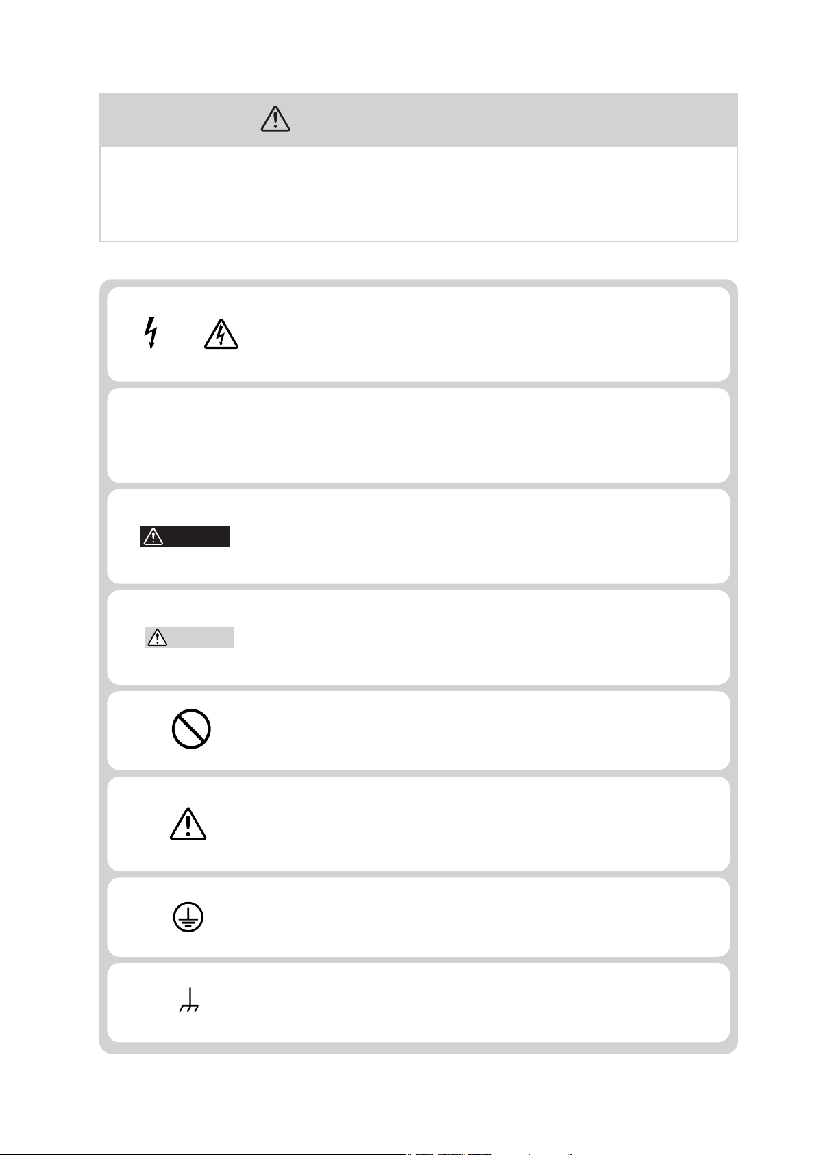
Safety Symbols
For the safe use and safe maintenance of this product, the following
symbols are used throughout this manual and on the product. Understand the meanings of the symbols and observe the instructions they
indicate (the choice of symbols used depends on the products).
Indicates that a high voltage (over 1000 V) is used here. Touch-
OR
ing the part causes a possibly fatal electric shock. If physical
contact is required by your work, start work only after you make
sure that no voltage is output here.
DANGER
WARNING
CAUTION
Indicates an imminently hazardous situation which, if ignored,
will result in death or serious injury.
Indicates a potentially hazardous situation which, if ignored,
could result in death or serious injury.
Indicates a potentially hazardous situation which, if ignored, may
result in damage to the product and other property.
Shows that the act indicated is prohibited.
Is placed before the sign “DANGER,” “WARNING,” or “CAUTION” to emphasize these. When this symbol is marked on the
product, see the relevant sections in this manual.
Indicates a protective conductor terminal.
Indicates a chassis (frame) terminal.
PLZ-U Safety Symbols I
Operation
Manual
Line
Voltage
Safety Precautions
The following safety precautions must be observed to avoid
fire hazard, electrical shock, accidents, and other failures.
Keep them in mind and make sure that all of them are observed
properly.
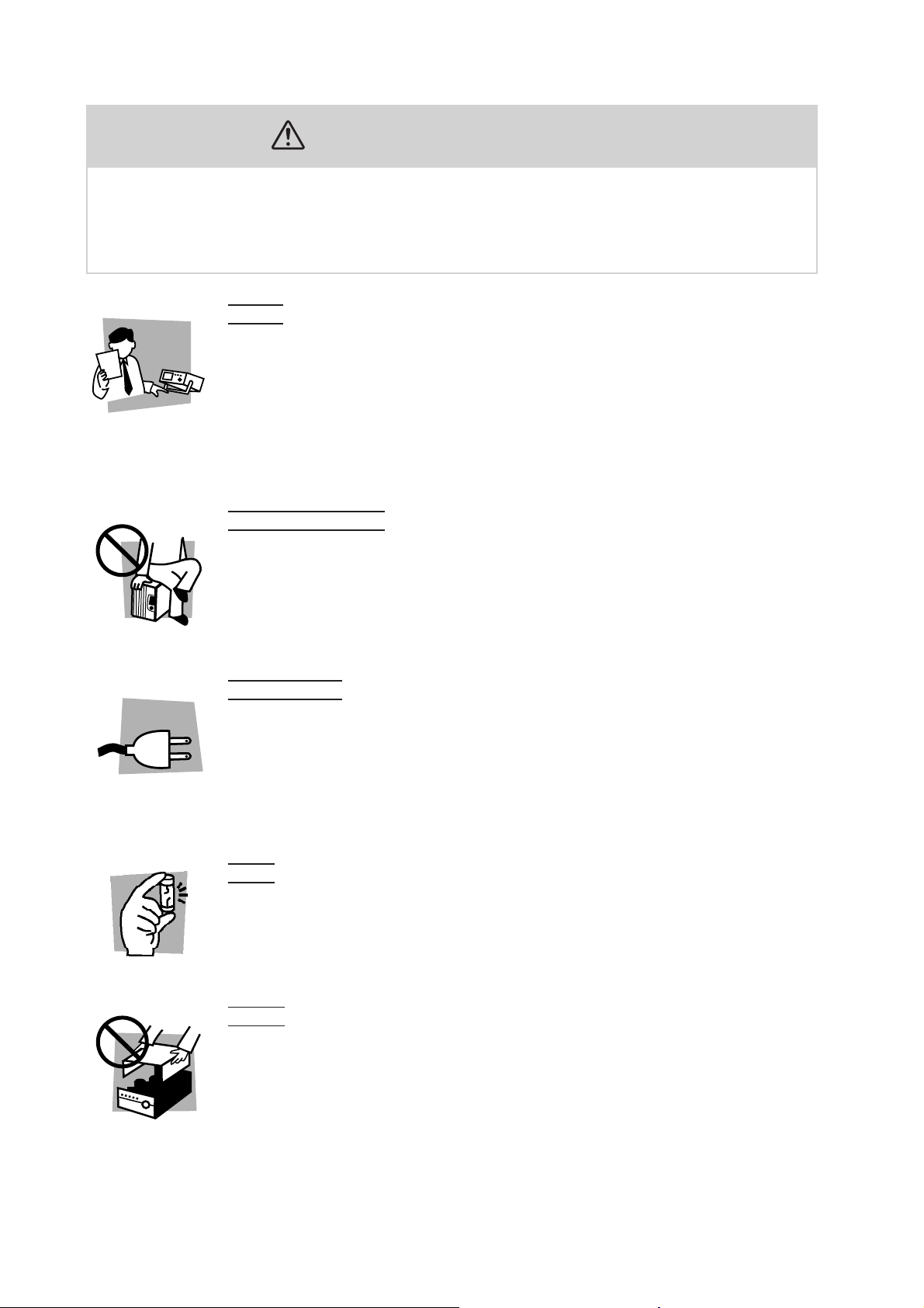
Users
• This product must be used only by qualified personnel who understand the contents of this operation manual.
• If it is handled by disqualified personnel, personal injury may result. Be sure to handle it under supervision of qualified personnel (those who have electrical knowledge.)
• This product is not designed or manufactured for general home or consumer use.
Purposes of use
• Do not use the product for purposes other than those described in the operation
manual.
Input power
• Use the product with the specified input power voltage.
• For applying power, use the power cord provided. Note that the provided power
cord is not use with some products that can switch among different input power
voltages or use 100 V and 200 V without switching between them. In such a case,
use an appropriate power cord.
Fuse
• With products with a fuse holder on the exterior surface, the fuse can be replaced
with a new one. When replacing a fuse, use the one which has appropriate shape,
ratings, and specifications.
Cover
• There are parts inside the product which may cause physical hazards. Do not
remove the external cover.
II Safety Precautions PLZ-U

Installation
• When installing products be sure to observe 2.2, “Precautions Concerning Installation Location” described in this manual.
• To avoid electrical shock, connect the protective ground terminal to electrical
ground (safety ground).
• When connecting the power cord to a switchboard, be sure work is performed by
a qualified and licensed electrician or is conducted under the direction of such a
person.
• When installing products with casters, be sure to lock the casters.
Relocation
• Turn off the power switch and then disconnect all cables when relocating the
product.
• Use two or more persons when relocating the product which weights more than
18 kg. The weight of the products can be found on the rear panel of the product
and/or in this operation manual.
• Use extra precautions such as using more people when relocating into or out of
present locations including inclines or steps. Also handle carefully when relocating tall products as they can fall over easily.
• Be sure the operation manual be included when the product is relocated.
Check?
Operation
• Check that the AC input voltage setting and the fuse rating are satisfied and that
there is no abnormality on the surface of the power cord. Be sure to unplug the
power cord or stop applying power before checking.
• If any abnormality or failure is detected in the products, stop using it immediately.
Unplug the power cord or disconnect the power cord from the switchboard. Be
careful not to allow the product to be used before it is completely repaired.
• For output wiring or load cables, use connection cables with larger current capacity.
• Do not disassemble or modify the product. If it must be modified, contact Kikusui
distributor/agent.
Maintenance and checking
• To avoid electrical shock, be absolutely sure to unplug the power cord or stop
applying power before performing maintenance or checking.
• Do not remove the cover when performing maintenance or checking.
• To maintain performance and safe operation of the product, it is recommended
that periodic maintenance, checking, cleaning, and calibration be performed.
Service
• Internal service is to be done by Kikusui service engineers. If the product must be
adjusted or repaired, contact Kikusui distributor/agent.
PLZ-U Safety Precautions III

Contents
Safety Symbols ____________________________________________ I
Safety Precautions ________________________________________ II
Chapter 1 General Description 1-1
Chapter 2 Installation and Preparation 2-1
1.1 About This Manual - - - - - - - - - - - - - - - - - - - - - - - - - - - - - - - - - - - - - 1-2
1.2 Product Overview - - - - - - - - - - - - - - - - - - - - - - - - - - - - - - - - - - - - - - 1-2
1.3 Features - - - - - - - - - - - - - - - - - - - - - - - - - - - - - - - - - - - - - - - - - - - - - 1-3
1.4 Options - - - - - - - - - - - - - - - - - - - - - - - - - - - - - - - - - - - - - - - - - - - - - 1-5
2.1 Checking the Package Contents - - - - - - - - - - - - - - - - - - - - - - - - - - - - - 2-2
2.1.1 Frame - - - - - - - - - - - - - - - - - - - - - - - - - - - - - - - - - - - - - - - - 2-2
2.1.2 Load Unit - - - - - - - - - - - - - - - - - - - - - - - - - - - - - - - - - - - - - - 2-3
2.2 Precautions Concerning Installation Location - - - - - - - - - - - - - - - - - - - - 2-4
2.3 Precautions When Moving the PLZ-U - - - - - - - - - - - - - - - - - - - - - - - - - 2-5
2.4 Installing Load Units - - - - - - - - - - - - - - - - - - - - - - - - - - - - - - - - - - - - 2-6
2.5 Connecting the Power Cord - - - - - - - - - - - - - - - - - - - - - - - - - - - - - - - - 2-8
2.6 Power Up - - - - - - - - - - - - - - - - - - - - - - - - - - - - - - - - - - - - - - - - - - - - 2-9
2.7 Load Wiring - - - - - - - - - - - - - - - - - - - - - - - - - - - - - - - - - - - - - - - - - 2-11
2.7.1 Precautions Concerning Wiring - - - - - - - - - - - - - - - - - - - - - - - 2-11
2.7.2 Connection to the Load Input Terminal on the Rear Panel - - - - - 2-15
2.7.3 Connection to the Load Input Terminal on the Front Panel - - - - 2-17
Chapter 3 Names and Functions of Parts 3-1
3.1 Front Panel - - - - - - - - - - - - - - - - - - - - - - - - - - - - - - - - - - - - - - - - - - - 3-2
3.1.1 Frame - - - - - - - - - - - - - - - - - - - - - - - - - - - - - - - - - - - - - - - - 3-2
3.1.2 Load Unit (Channel) - - - - - - - - - - - - - - - - - - - - - - - - - - - - - - - 3-8
3.2 Rear Panel - - - - - - - - - - - - - - - - - - - - - - - - - - - - - - - - - - - - - - - - - - 3-11
Chapter 4 Basic Operation 4-1
4.1 Panel Control Basics - - - - - - - - - - - - - - - - - - - - - - - - - - - - - - - - - - - - 4-2
4.2 Load On/Off - - - - - - - - - - - - - - - - - - - - - - - - - - - - - - - - - - - - - - - - - - 4-3
4.3 Basic Operation - - - - - - - - - - - - - - - - - - - - - - - - - - - - - - - - - - - - - - - - 4-6
4.4 Protection Functions and Alarms - - - - - - - - - - - - - - - - - - - - - - - - - - - - 4-9
4.4.1 Protection Function - - - - - - - - - - - - - - - - - - - - - - - - - - - - - - - 4-9
4.4.2 Alarms - - - - - - - - - - - - - - - - - - - - - - - - - - - - - - - - - - - - - - - - 4-10
4.4.3 Setting the Trip Points - - - - - - - - - - - - - - - - - - - - - - - - - - - - - 4-12
Chapter 5 Application Operation 5-1
5.1 Soft Start - - - - - - - - - - - - - - - - - - - - - - - - - - - - - - - - - - - - - - - - - - - - 5-2
5.2 ABC Preset Memories - - - - - - - - - - - - - - - - - - - - - - - - - - - - - - - - - - - 5-3
5.3 Switching Function - - - - - - - - - - - - - - - - - - - - - - - - - - - - - - - - - - - - - 5-5
IV Contents PLZ-U

5.4 Setting the Slew Rate - - - - - - - - - - - - - - - - - - - - - - - - - - - - - - - - - - - - 5-7
5.5 Elapsed Time Display and Auto Load Off Timer - - - - - - - - - - - - - - - - - 5-8
5.6 Sequence Function - - - - - - - - - - - - - - - - - - - - - - - - - - - - - - - - - - - - - 5-9
5.6.1 Editing the Sequence - - - - - - - - - - - - - - - - - - - - - - - - - - - - - - - 5-9
5.6.2 Executing the Sequence - - - - - - - - - - - - - - - - - - - - - - - - - - - - 5-11
5.6.3 Example Sequence - - - - - - - - - - - - - - - - - - - - - - - - - - - - - - - 5-13
5.7 Remote Sensing Function - - - - - - - - - - - - - - - - - - - - - - - - - - - - - - - - 5-15
5.8 Key Lock Function - - - - - - - - - - - - - - - - - - - - - - - - - - - - - - - - - - - - 5-16
5.9 Configuration Settings - - - - - - - - - - - - - - - - - - - - - - - - - - - - - - - - - - 5-17
5.10 External Control - - - - - - - - - - - - - - - - - - - - - - - - - - - - - - - - - - - - - - 5-21
5.10.1 FRAME CONT Connector - - - - - - - - - - - - - - - - - - - - - - - - - - 5-21
5.10.2 CH CONT Connector - - - - - - - - - - - - - - - - - - - - - - - - - - - - - 5-25
5.11 Parallel Operation - - - - - - - - - - - - - - - - - - - - - - - - - - - - - - - - - - - - - 5-29
5.12 Setup Memories - - - - - - - - - - - - - - - - - - - - - - - - - - - - - - - - - - - - - - 5-31
5.13 Factory Default Settings - - - - - - - - - - - - - - - - - - - - - - - - - - - - - - - - - 5-32
5.13.1 Factory Default Settings (General) - - - - - - - - - - - - - - - - - - - - - 5-33
5.13.2 Factory Default Settings of ABC Preset Memories - - - - - - - - - - 5-34
5.13.3 Factory Default Settings of Setup Memories - - - - - - - - - - - - - - 5-34
Chapter 6 Remote Control 6-1
6.1 Overview - - - - - - - - - - - - - - - - - - - - - - - - - - - - - - - - - - - - - - - - - - - - 6-2
6.2 Instrument Interface Standard - - - - - - - - - - - - - - - - - - - - - - - - - - - - - - 6-2
6.3 Using SCPI Commands - - - - - - - - - - - - - - - - - - - - - - - - - - - - - - - - - - 6-3
6.3.1 Hierarchy of SCPI Commands - - - - - - - - - - - - - - - - - - - - - - - - - 6-3
6.3.2 Parameter Format - - - - - - - - - - - - - - - - - - - - - - - - - - - - - - - - - 6-6
6.4 Interface Setup - - - - - - - - - - - - - - - - - - - - - - - - - - - - - - - - - - - - - - - 6-10
6.4.1 GPIB Control - - - - - - - - - - - - - - - - - - - - - - - - - - - - - - - - - - - 6-10
6.4.2 RS-232C Control - - - - - - - - - - - - - - - - - - - - - - - - - - - - - - - - 6-11
6.5 SCPI Commands - - - - - - - - - - - - - - - - - - - - - - - - - - - - - - - - - - - - - - 6-13
6.5.1 IEEE 488.2 Common Commands - - - - - - - - - - - - - - - - - - - - - - 6-13
6.5.2 Channel Commands - - - - - - - - - - - - - - - - - - - - - - - - - - - - - - 6-17
6.5.3 Measurement Commands - - - - - - - - - - - - - - - - - - - - - - - - - - - 6-18
6.5.4 Configuration and Operation Commands - - - - - - - - - - - - - - - - 6-19
6.5.5 Trigger Commands - - - - - - - - - - - - - - - - - - - - - - - - - - - - - - - 6-24
6.5.6 Switching Function Commands - - - - - - - - - - - - - - - - - - - - - - 6-26
6.5.7 Input State Commands - - - - - - - - - - - - - - - - - - - - - - - - - - - - 6-27
6.6 Status Registers - - - - - - - - - - - - - - - - - - - - - - - - - - - - - - - - - - - - - - - 6-33
6.6.1 SCPI Registers - - - - - - - - - - - - - - - - - - - - - - - - - - - - - - - - - - 6-33
6.6.2 IEEE488.2 Registers - - - - - - - - - - - - - - - - - - - - - - - - - - - - - - 6-50
Chapter 7 Maintenance 7-1
7.1 Maintenance - - - - - - - - - - - - - - - - - - - - - - - - - - - - - - - - - - - - - - - - - - 7-2
7.1.1 Cleaning the Panels - - - - - - - - - - - - - - - - - - - - - - - - - - - - - - - - 7-2
7.1.2 Cleaning the Dust Filter - - - - - - - - - - - - - - - - - - - - - - - - - - - - - 7-2
7.1.3 Inspecting the Power Cord - - - - - - - - - - - - - - - - - - - - - - - - - - - 7-3
PLZ-U Contents V

7.1.4 Internal Inspection - - - - - - - - - - - - - - - - - - - - - - - - - - - - - - - - 7-3
7.2 Confirming status of the fuse - - - - - - - - - - - - - - - - - - - - - - - - - - - - - - - 7-4
7.3 Calibration - - - - - - - - - - - - - - - - - - - - - - - - - - - - - - - - - - - - - - - - - - - 7-4
7.4 Malfunctions and Causes - - - - - - - - - - - - - - - - - - - - - - - - - - - - - - - - - 7-5
Chapter 8 Specifications 8-1
8.1 Electrical Specifications - - - - - - - - - - - - - - - - - - - - - - - - - - - - - - - - - - 8-2
8.2 Dimensions - - - - - - - - - - - - - - - - - - - - - - - - - - - - - - - - - - - - - - - - - - - 8-8
Appendix A-1
A.1 Operating Area of the PLZ-U - - - - - - - - - - - - - - - - - - - - - - - - - - - - - -A-1
A.2 Basic Operation Modes - - - - - - - - - - - - - - - - - - - - - - - - - - - - - - - - - - -A-2
A.2.1 Operation of the CC Mode - - - - - - - - - - - - - - - - - - - - - - - - - - A-2
A.2.2 Operation of the CR Mode - - - - - - - - - - - - - - - - - - - - - - - - - - -A-4
A.2.3 Operation of the CV Mode - - - - - - - - - - - - - - - - - - - - - - - - - - A-6
A.2.4 Operation of the CC+CV Mode - - - - - - - - - - - - - - - - - - - - - - - A-8
A.2.5 Operation of the CR+CV Mode - - - - - - - - - - - - - - - - - - - - - - - A-10
A.3 Operating Area of Each Model - - - - - - - - - - - - - - - - - - - - - - - - - - - -A-13
A.3.1 Operating Area of the PLZ150U - - - - - - - - - - - - - - - - - - - - - - A-13
A.3.2 Operating Area of the PLZ70UA - - - - - - - - - - - - - - - - - - - - - -A-14
A.4 Sequence Program Creation Table
A.5 SCPI Command Reference - - - - - - - - - - - - - - - - - - - - - - - - - - - - - - - A-16
A.6 Error Messages - - - - - - - - - - - - - - - - - - - - - - - - - - - - - - - - - - - - - - - A-23
A.6.1 Overview - - - - - - - - - - - - - - - - - - - - - - - - - - - - - - - - - - - - - A-23
A.6.2 A List of Errors - - - - - - - - - - - - - - - - - - - - - - - - - - - - - - - - - A-23
---------------------- A-15
Index I- 1
VI Contents PLZ-U

1
1
Chapter 1 General Description
This chapter gives an overview and describes the features of the PLZ-U.
PLZ-U General Description 1-1

1.1 About This Manual
This operation manual covers the following PLZ-U Series Electronic Load Units.
Frame
• PLZ-50F
• PLZ-30F
Load unit
• PLZ150U
• PLZ70UA
Product version covered
This operation manual covers products with frame ROM version 1.0X and load unit
ROM version 2.0X.
When contacting us about the product, please provide us the following information.
Model
ROM version
Manufacturing number (indicated at the lower section on the rear panel on the
frame and on the top panel on the load unit)
For the procedure of confirming the ROM version, see section 2.6, “Power Up.”
1.2 Product Overview
The PLZ-U Series Electronic Load Unit is a compact, high-performance, multichannel electronic load unit that has three operation modes: constant current, constant resistance, and constant voltage.
The PLZ-U consists of a frame and load units. Load units are inserted into the frame
(control section) for operation. The PLZ-30F and PLZ-50F Frames can accommodate up to 3 channels and 5 channels of load units, respectively.
The current capacity or power capacity can be increased through a parallel operation of load units. The load units can be combined to produce a power capacity from
75 W to 750 W (when five PLZ150Us are installed into the PLZ-50F).
In addition to high-speed response and highly precise preset resolution, various
functions are provided including the soft start function, variable slew rates, switching function, ABC preset memories, four setup memories, and sequence function.
Because the PLZ-U comes standard with GPIB and RS-232C communication functions, it can easily be incorporated into various test and inspection systems. The
communication functions are useful for testing batteries, DC/DC converters,
switching power supplies, and multi-output power supplies.
1-2 General Description PLZ-U

1.3 Features
In addition to the advanced constant current, constant resistance, and constant volt-
age functions, the PLZ-U Series Electronic Load Unit offers wide variety of other
features.
■ Compact and light
Compact and light weighing only approximately 11 kg and 17 kg for 3 channels and
5 channels, respectively.
■ High-speed response
In constant current mode, a current rise and fall slew rate of 2.4 A/μs (PLZ150U) is
possible (converts to a rise and fall time of 10 μs). Simulations that closely resemble
a real load are possible by using the PLZ-U as a load for DC power transient
response tests and as a dummy load
■ High precision and high resolution
Three ranges are built into the PLZ-U achieving both wide dynamic range and high
resolution. The PLZ-U provides displays with up to 5 digits for voltage, current, and
power measurement functions as well as minimum preset resolutions of 10 μA
(PLZ70UA) and 20 μA (PLZ150U).
■ Variable slew rate
The current slew rate can be varied continuously in constant current mode and con-
stant resistance mode. This feature allows the suppression of transient voltage drops
due to the wiring inductance that occurs when a load is switched and transient volt-
ages of constant voltage power supplies, etc.
■ Multi channels
Up to five and three channels can be installed into the PLZ-50F and PLZ-30F, respec-
tively. Each channel is isolated and can be used independently or linked with each
other. Different units (PLZ150Us and PLZ70UAs) can be installed in the frame.
■ Low noise
High reliability and low noise have been achieved by the adoption of a heat sensing
variable speed fan and the enhanced cooling structure.
■ Large capacity
Parallel operation is possible on up to five adjacent load units of the same type.
Five PLZ70UAs installed in PLZ-50F operating in parallel produce 375 W.
Five PLZ150Us installed in PLZ-50F operating in parallel produce 750 W.
■ 0 V type
The PLZ70UA is a 0 V input operating voltage unit. This feature is a must for single
cell tests of fuel cells. Moreover, the operating voltage of semiconductor devices is
decreasing more and more due to the reduction of the power consumption and min-
iaturization of the semiconductor process. The PLZ70UA can be used to evaluate
the power supplies for these types of applications.
PLZ-U General Description 1-3

■ ABC preset memories
Three presets that are most frequently used can be stored for each operation mode
and range. This allows quick switching of settings even when the load is turned on.
■ Load simulations
In constant current and constant resistance modes, a sequence program can be created with up to 255 steps at a minimum interval of 1 ms. Independent settings can
be entered on each channel simultaneously.
■ Outstanding operability
Setup operations have been consolidated on the frame panel. Each channel can be
configured with one hand while viewing the measured voltage and current. Rotary
knobs with an analog feel and simple interface make the operation of the PLZ-U
easy even for first-time users.
■ Load input terminal
The load input terminal is provided on both the front panel and rear panel making
the load unit suitable for embedded applications.
■ Remote sensing terminal
Remote sensing terminals are provided on both the front panel and rear panel allowing more accurate characteristics tests.
■ Extensive protection functions
Equipped with overcurrent protection (OCP), overpower protection (OPP), overvoltage protection (OVP), undervoltage protection (UVP), overheat protection
(OHP), and reverse connection protection (RVP) functions. Since OCP, OPP, and
UVP can be varied for each channel, protection can be optimized for each equipment under test.
■ External control
External voltage reference can be applied and the load can be turned on/off on each
channel. You can recall channel-linked ABC preset memories, recall setup memories, and turn on/off the load from the frame control connector.
■ Inter-frame control
By connecting the frame control signal, multiple frames can be controlled from a
single frame. You can collectively turn on/off the load and recall reset values.
■ Setup memories
Four sets of panel settings can be stored. You can easily recall settings according to
the application and perform tests.
■ Standard GPIB, and RS-232C communication functions
GPIB and RS-232C come standard. Since panel settings, input voltage, current, and
power can be read through the interface, the PLZ-U can be embedded easily into
various test systems.
1-4 General Description PLZ-U

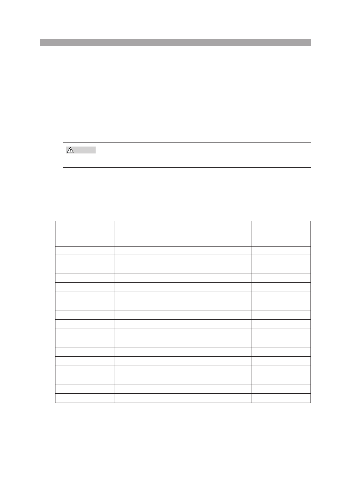
1.4 Options
Rack mounting option
The following rack mounting options are available.
For details, contact your Kikusui agent or distributor.
Name Model Applicable Model Note
Rack mount bracket
(Fig. 1-1)
Rack mount bracket
(Fig. 1-2)
Table 1-1 Rack mounting options
KRB3-PLZ-50F
PLZ-50F
KRB150-PLZ-50F Milli rack JIS standard
KRB3-PLZ-30F
PLZ-30F
KRB150-PLZ-30F Milli rack JIS standard
KRB3-PLZ-50F
Inch rack EIA standard
Inch rack EIA standard
465 (18.31)
484.4 (19.07)
KRB150-PLZ-50F
465
484.4
Fig.1-1 Rack mount bracket (PLZ-50F)
57 (2.24)
37.5
(1.48)
10024.5
149
132 (5.20)
Unit: mm (inch)
Unit: mm
PLZ-U General Description 1-5
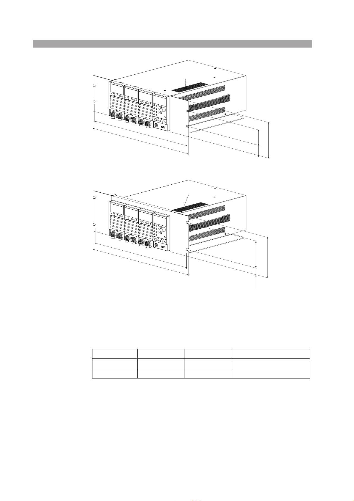
465 (18.31)
482 (18.98)
KRB3-PLZ-30F
KRB150-PLZ-30F
Unit: mm (inch)
57 (2.24)
132 (5.20)
37.5
(4.48)
Unit: mm
Fig. 1-2 Rack mount bracket (PLZ-30F)
Control flat cables
Control cables that connect frames for inter-frame control. The following two types
of cables are available.
Model
PC01-PLZ-4W 84540 300 mm
PC02-PLZ-4W 84550 550 mm
460
480
Cord Length
149
24.5 100
Application
Connection between frames
1-6 General Description PLZ-U

2
2
Chapter 2 Installation and
Preparation
This chapter describes the procedures of unpacking and preparation before using
the PLZ-U.
PLZ-U Installation and Preparation 2-1
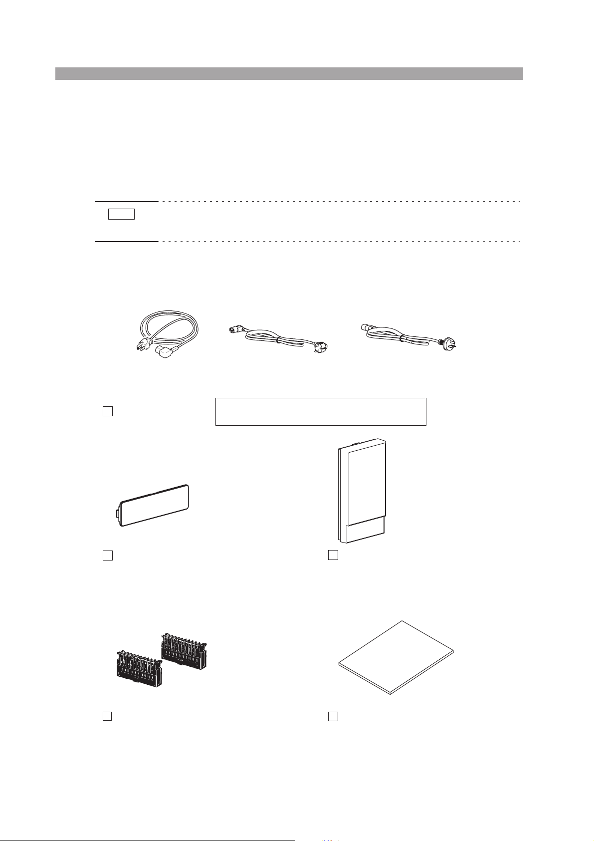
2.1 Checking the Package Contents
When you receive the product, check that all accessories indicated below are
included and that the accessories have not been damaged during transportation.
If any of the accessories are damaged or missing, contact your Kikusui agent or distributor.
NOTE
2.1.1 Frame
Rating: 125 Vac/10 A
Plug: NEMA5-15
[85-AA-0003] [85-AA-0005]
Power cord (1 pc.)
• It is recommended that all packing materials be saved, in case the product needs
to be transported at a later date.
or or
Rating: 250 Vac/10 A
Plug: CEE7/7
The power cord that is provided varies depending on the
destination for the product at the factory-shipment.
PLZ-30F (2 pcs. maximum)
PLZ-50F (4 pcs. maximum)
Rateing: 250 Vac/10 A
Plug: GB1002
[85-10-0790]
PLZ-30F (2 pcs. maximum)
PLZ-50F (4 pcs. maximum)
[P1-000-406]
Blank panel (rear)
[Attached to the product.]* [Attached to the product.]*
* In products that have load units installed, blank panels are installed in the empty slots.
In products that contain the frame alone, the maximum number of blank panels are installed.
[84-49-0071]
FRAME CONT protection dummy plug (2 pcs.)
[Attached to the product.]
Blank panel (front)
Operation manual (this manual, 1 pc.)
[P1-000-405]
Fig.2-1 Accessories (frame)
2-2 Installation and Preparation PLZ-U
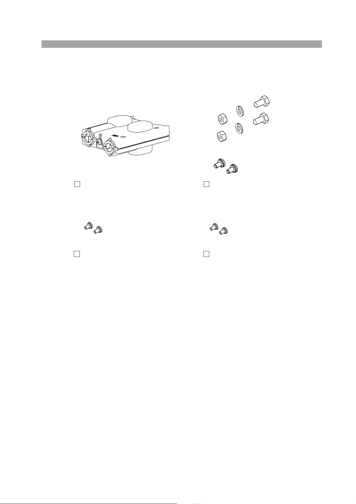
2.1.2 Load Unit
The following accessories are included with each load unit.
[M1-100-006]
[M5-101-006]
[M4-100-006]
[Q1-500-077]
Rear load input terminal cover Set of screws for the load input terminal
(2 pcs. each)
[M3-112-012]
Rear sensing terminal screws (M3-6: 2 pcs.)
[Attached to the load unit.]
Load unit attachment screws (M3-10, 2 pcs.)
[Attached to the load unit.]
[M3-112-026]
[M3-112-014]
Fig. 2-2 Accessories (load unit)
PLZ-U Installation and Preparation 2-3

2.2 Precautions Concerning Installation Location
This section describes the precautions to be taken when installing the product. Make
sure to observe them.
■ Do not use the PLZ-U in a flammable atmosphere.
To prevent the possibility of explosion or fire, do not use the PLZ-U near alcohol,
thinner or other combustible materials, or in an atmosphere containing such vapors.
■ Avoid locations where the PLZ-U is exposed to high temperature or direct sunlight.
Do not place the PLZ-U near a heater or in areas subject to drastic temperature
changes.
Operating temperature range: 0 °C to +40 °C (32 °F to 104 °F)
Storage temperature range: –20 °C to +70 °C (-4 °F to 158 °F)
■ Avoid humid environments.
Do not place the PLZ-U in high-humidity locations--near a boiler, humidifier, or
water supply.
Condensation may occur even within the operating humidity range. In such cases,
do not use the PLZ-U until the condensation dries up completely.
Operating humidity range: 20 % to 85 % RH (no condensation)
Storage humidity range: 0 to 90 % RH (no condensation)
■ Do not place the PLZ-U in a corrosive atmosphere.
Do not install the PLZ-U in a corrosive atmosphere or in environments containing
sulfuric acid mist, etc. This may cause corrosion of various conductors and bad contacts of connectors inside the PLZ-U leading to malfunction and failure, or in the
worst case, a fire.
■ Do not place the PLZ-U in a dusty location.
Accumulation of dust can lead to electric shock or fire.
■ Do not use the PLZ-U where ventilation is poor.
The PLZ-U employs a forced air cooling system. Air is taken in from air inlets
located on panels other than the rear panel and exhausted from the air outlet on the
rear panel. Secure adequate space around the PLZ-U to prevent the possibility of
fire caused by accumulation of heat. Allow at least 20 cm of space between the air
inlet/outlet and the wall (or obstacles).
Hot air (approximately 20 °C higher than the ambient temperature) is exhausted
from the air outlet. Do not place objects that are affected by heat near the air outlet.
2-4 Installation and Preparation PLZ-U

■ Secure adequate space around the power switch.
Do not place the PLZ-U in a location that would result in poor accessibility to the
switch. And, do not place objects near the switch that would result in poor accessibility.
■ Do not place objects on the PLZ-U.
Placing objects on top of the PLZ-U can cause failures (especially heavy objects).
■ Do not place the PLZ-U on an inclined surface or location sub-
ject to vibrations.
The PLZ-U may fall or tip over causing damages and injuries.
■ Do not use the PLZ-U in a location where strong magnetic or
electric fields are nearby or a location where large amount of
distortion and noise is present on the input power supply
waveform.
The PLZ-U may malfunction.
■ Do not use the PLZ-U near highly sensitive measuring instru-
ments or transceivers.
The noise generated by the PLZ-U may affect them
■ Use the PLZ-U in an industrial environment.
The PLZ-U may cause interference if used in residential areas. Such use must be
avoided unless the user takes special measures to reduce electromagnetic emissions
to prevent interference to the reception of radio and television broadcasts.
2.3 Precautions When Moving the PLZ-U
When moving or transporting the PLZ-U to the installation site, observe the following precautions.
■ Turn off the POWER switch.
Moving the PLZ-U while the power is turned on can cause electric shock or damage
to it.
■ Remove all wiring.
Moving the PLZ-U with the cables connected can cause wires to break or injuries
due to the PLZ-U falling over.
PLZ-U Installation and Preparation 2-5
2.4 Installing Load Units
l
l.
.
I
gul
.
l)
ll
.
Install the load units into the empty slots of the frame. Channel numbers are automatically assigned to the load units. The left most load units is CH1.
WARNING
• Turn off the POWER switch. Installing a load unit while the power is turned
on can cause electric shock or damage to the PLZ-U.
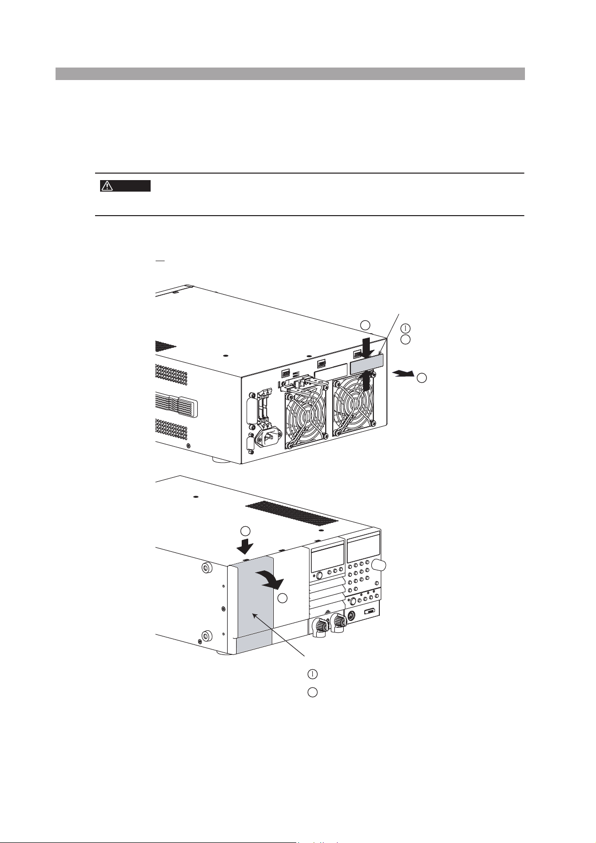
■ Installation procedure
1. Remove the blank panels (front and rear panels) from the slot where
the load unit is to be installed.
Blank panel (rear panel)
1
Pinch the center section of the b
Pull it off towards you
2
ank pane
1
2
Blank panel (front pane
nsert a flat-blade screwdriver or something similar into
the rectan
Pu
ar hole on the top of the cover
the blank panel off towards you
Fig. 2-3 Removing the blank panels
2-6 Installation and Preparation PLZ-U
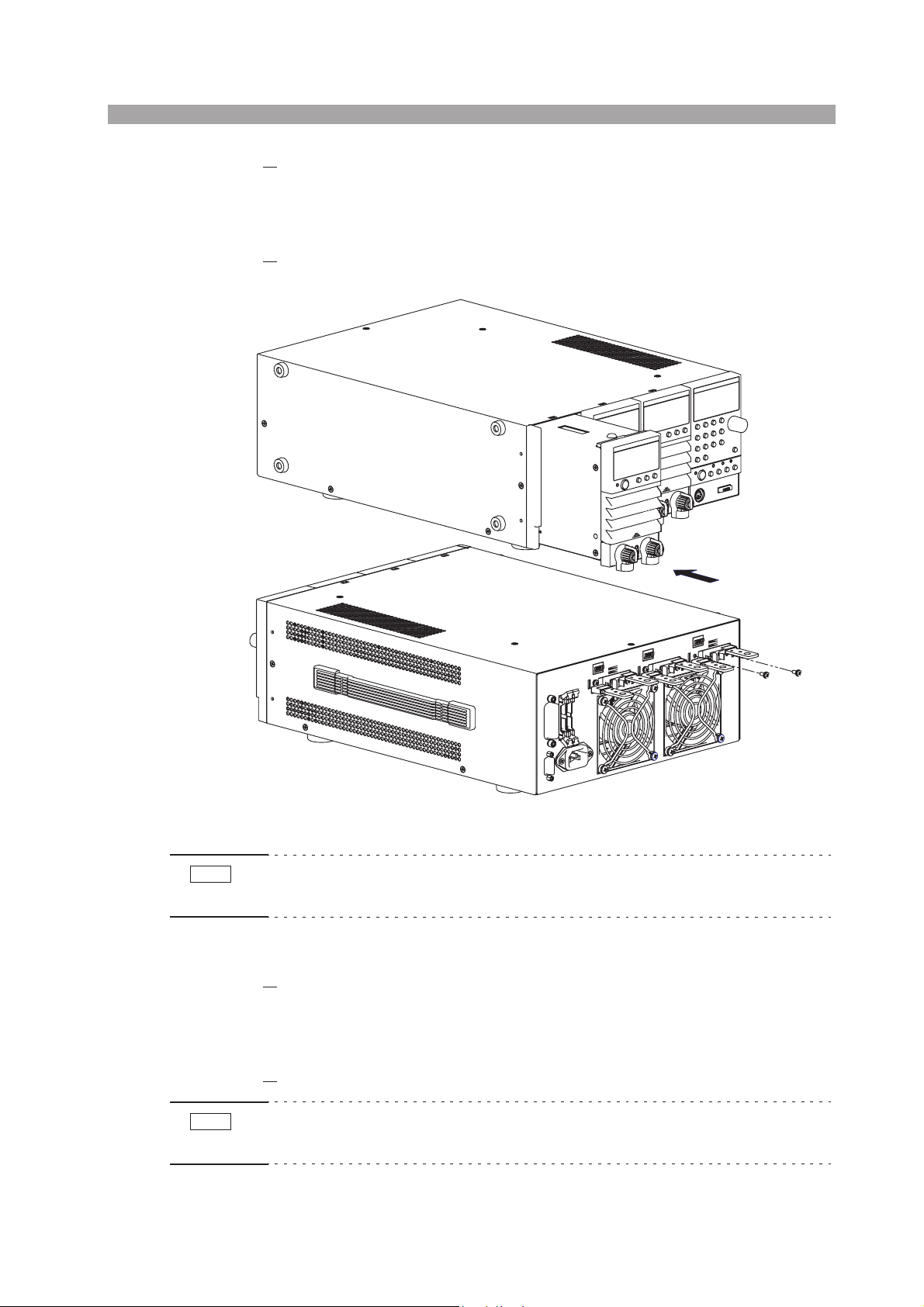
2. Carry the load unit with both hands and slowly insert it into the desired
slot.
Check that the panel surface of the load unit is nearly flat with the frame panel
surface.
3.
Fix the load unit in place using the unit attachment screws (M3-10) provided.
Insert the load unit into the slot.
NOTE
Screw it in place.
Fig. 2-4 Installing the load unit
• The load unit is securely grounded when it is screwed in place. For safety reasons,
be sure to fix the load unit using screws.
■ Removal procedure
1. Remove the unit attachment screws (M3-10) indicated in installation
procedure step 3.
The screws that you removed are needed when you install the load unit again.
Be sure to store them in a safe place (do not lose them).
2.
Hold the load unit with both hands and slowly remove it from the slot.
NOTE
• Be sure to attach blank panels on both the front and rear panels in empty slots. If
you do not, the cooling effect deteriorates, and the PLZ-U can malfunction.
PLZ-U Installation and Preparation 2-7
2.5 Connecting the Power Cord
WARNING
NOTE
Risk of electric shock.
• The PLZ-U conforms to IEC Safety Class I (equipment that has a protec-
tive conductor terminal). Be sure to earth ground the product to prevent
electric shock.
• The PLZ-U is grounded through the power cord ground wire. Connect the
protective conductor terminal to earth ground.
• Use the supplied power cord to connect to the AC line. If the supplied power cord
cannot be used because the rated voltage or the plug shape is incompatible, have a
qualified engineer replace it with an appropriate power cord that is 3 m or less in
length. If obtaining a power cord is difficult, contact your Kikusui agent or distributor.
• The power cord with a plug can be used to disconnect the PLZ-U from the AC
power line in an emergency. Connect the plug to an easily accessible power outlet
so that the plug can be removed from the outlet at any time.
• Do not use the supplied power cord with other instruments.
The PLZ-U falls under IEC Overvoltage Category II (energy-consuming equipment
supplied from the fixed installation).
Check that the POWER switch is off.
1.
2.
Check whether or not the AC power line is compatible with the input rating of the PLZ-U.
The voltage that can be applied is any of the nominal power supply voltages in
the range of 100 VAC to 240 VAC.
The frequency is 50 Hz or 60 Hz. Frequency range: 47 Hz to 63 Hz
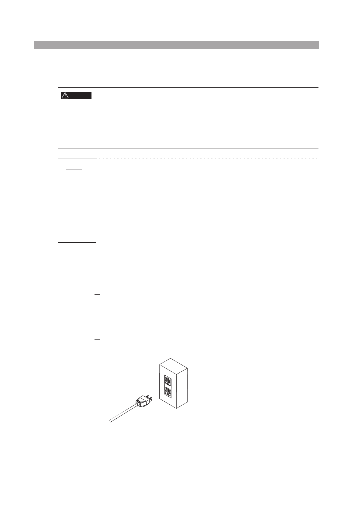
3.
Connect the power cord to the rear-panel AC INPUT.
4.
Connect the power cord plug to an outlet with a ground terminal.
Fig. 2-5 Power outlet with proper grounding
2-8 Installation and Preparation PLZ-U
2.6 Power Up
Operation check
1. Turn off ( ) the POWER switch.
2.
Check that the power cord is correctly connected.
See sections 2.5, “Connecting the Power Cord.”
3.
Check that nothing is connected to the DC INPUT (load input terminal)
on the front and rear panels.
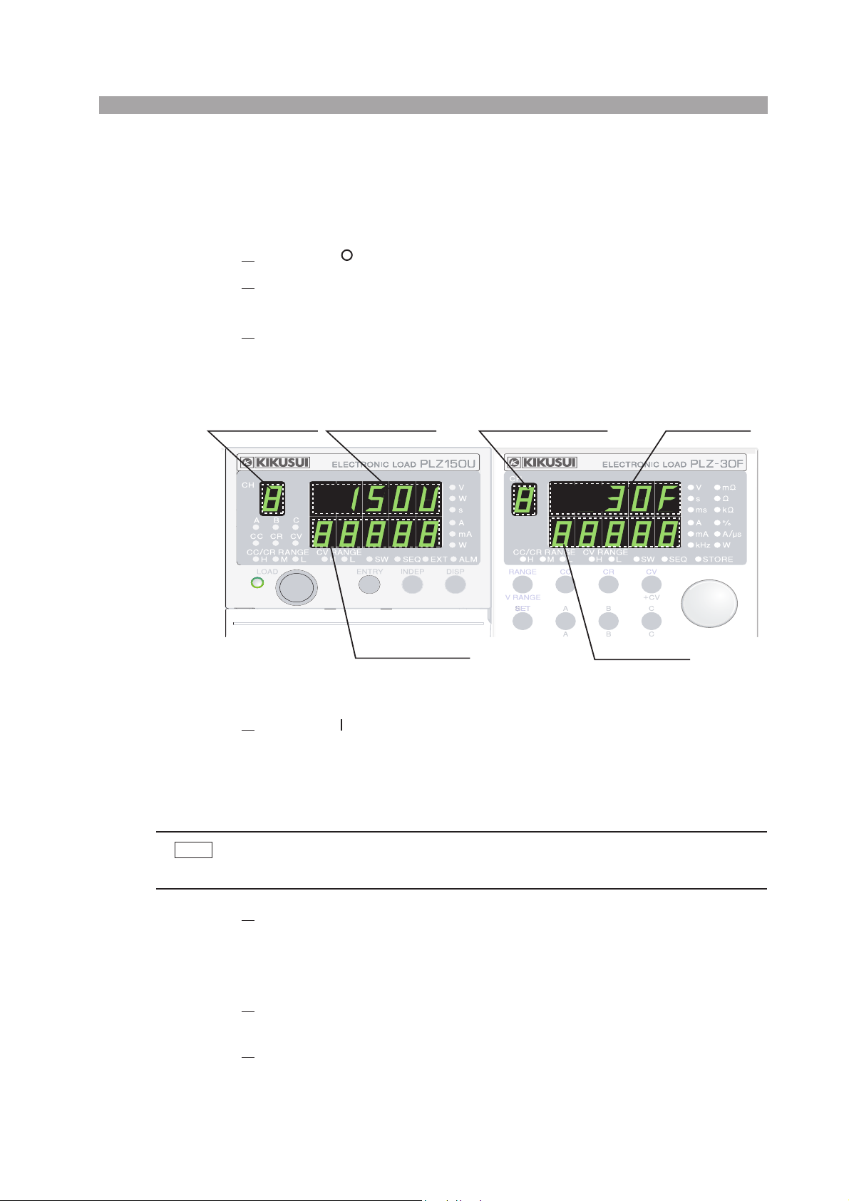
Load unit model
Channel number of
the load unit
70UA
150U
Load unit version
Channel number of the
selected load unit
Fig. 2-6 Model and version confirmation screen (example)
Turn on ( ) the POWER switch.
4.
All the LEDs illuminate once, and the model and version are displayed.
The model and version are displayed for approximately 1 second. Then,
the load unit displays the measured value, and the frame displays the
preset value.
Frame version
Frame model
30F
50F
NOTE
• The power-up operation takes up to 2 seconds per channel depending on
the length of the sequence program.
5.
Check the channel number display of the load unit.
Channel numbers are assigned to installed slots in order from the left facing
the front panel.
The measured value displayed on the load unit indicates coarse zero.
6.
Press the LOAD key of the frame and check that the LED located above
and to the left of the key illuminates.
7.
Press the LOAD key again and check that the LED located above and
to the left of the key turns off.
PLZ-U Installation and Preparation 2-9

8. Turn off the POWER switch to finish the operation check procedure.
CAUTION
• To prevent malfunction, allow at least 5 s between power cycles.
If the PLZ-U does not operate as described in the procedure
If the condition does not change even after taking the countermeasure indicated
below, contact your Kikusui agent.
■ Nothing is displayed.
Turn off the POWER switch and check the power cord connection.
■ The load unit freezes while displaying the model and version.
Turn off the POWER switch and check that the load unit is installed
correctly.
■ An alarm occurs.
See section 4.4, “Protection Functions and Alarms”
2-10 Installation and Preparation PLZ-U
2.7 Load Wiring
To ensure that the functions of the PLZ-U work accurately and reliably, all wires
must be connected correctly to their loads.
2.7.1 Precautions Concerning Wiring
■ Electric wire used
CAUTION
• Use a load wire with sufficient diameter for the current as well as non-flam-
mable or flame-resistant cover.
If the resistance of the load wire is large, a large voltage drop may occur when a current is supplied and the voltage at the load input terminal may fall below the minimum operating voltage. Refer to Table 2-1 and select as thick wires as possible.
Table2-1 Nominal cross-sectional area of wires and allowable
currents
Nominal
Cross-Sectional Area
2
]
[mm
2 14 (2.08) 27 10
3.5 12 (3.31) 37 -
5.5 10 (5.26) 49 20
8 8 (8.37) 61 30
14 6 (13.3) 88 50
22 4 (21.15) 115 80
30 2 (33.62) 139 -
38 1 (42.41) 162 100
50 1/0 (53.49) 190 -
60 2/0 (67.43) 217 -
80 3/0 (85.01) 257 200
100 4/0 (107.2) 298 -
125 - - 344 -
150 - - 395 300
200 - - 469 -
250 - - 556 -
325 - - 650 -
* Excerpts from Japanese laws related to electrical equipment.
AWG
(Reference
Cross-Sectional Area)
2
]
[mm
Allowable Current(*)
[A]
(Ta = 30 °C)
Kikusui-
Recommended Current
[A]
PLZ-U Installation and Preparation 2-11
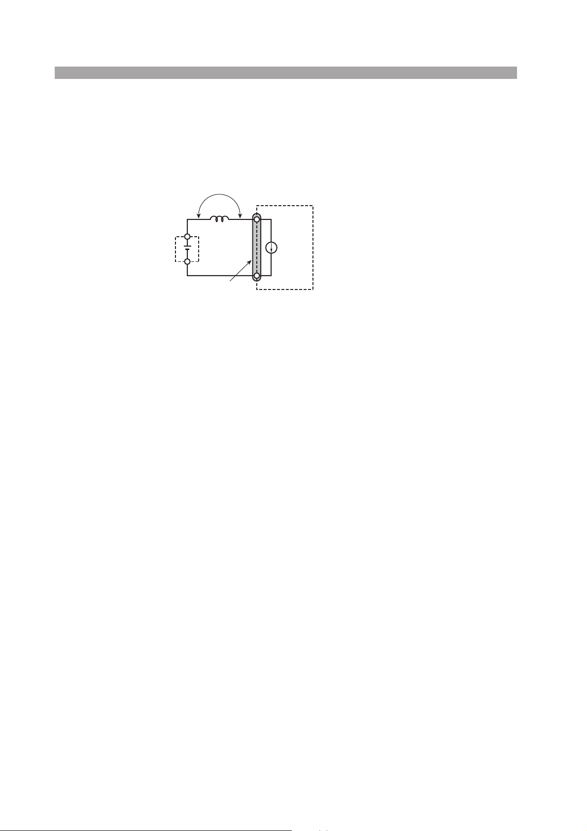
■ Load wire inductance
The load wiring has an inductance (L). When the current (I) varies in short time
period, it generates a large voltage at both ends of the wiring cable. This voltage
applies to all of the load input terminals of the PLZ-U when the impedance of the
EUT is relatively small. The voltage generated by the load wire inductance (L) and
the current variation (I) is expressed using the following equation.
E
L
EUT
Load input terminal
PLZ-U
+
I
ΔI/ΔT
E = L x (ΔI /ΔT)
E : Voltage generated by the wire inductance
L : Load wire inductance
ΔI : Amount of urrent variation
ΔT : Variation period of current
-
Fig. 2-7 Load wire and inductance
In general, the wire inductance can be measured approximately 1 μH per 1 meter. If
the 10 meters of load wires is connected between the EUT and the electronic load
(PLZ-U) with the current variation of 2 A/μs, the voltage generated by the wire
inductance will be 20 V.
The negative polarity of the load input terminal is the reference potential of the
external control signal, therefore, the device connected to the external control terminal may get malfunctioned.
When operating under the constant voltage (CV) mode or constant resistance (CR)
mode, the load current is varied by the voltage at the load input terminal, so the
operation can be affected easily by the generated voltage.
The wiring to the EUT should be twisted and the shortest as possible.
If the load wire is long or has a large loop, the wire inductance is increased. Consequently, the current variation that results when switching occurs will cause a large
voltage drop.
2-12 Installation and Preparation PLZ-U
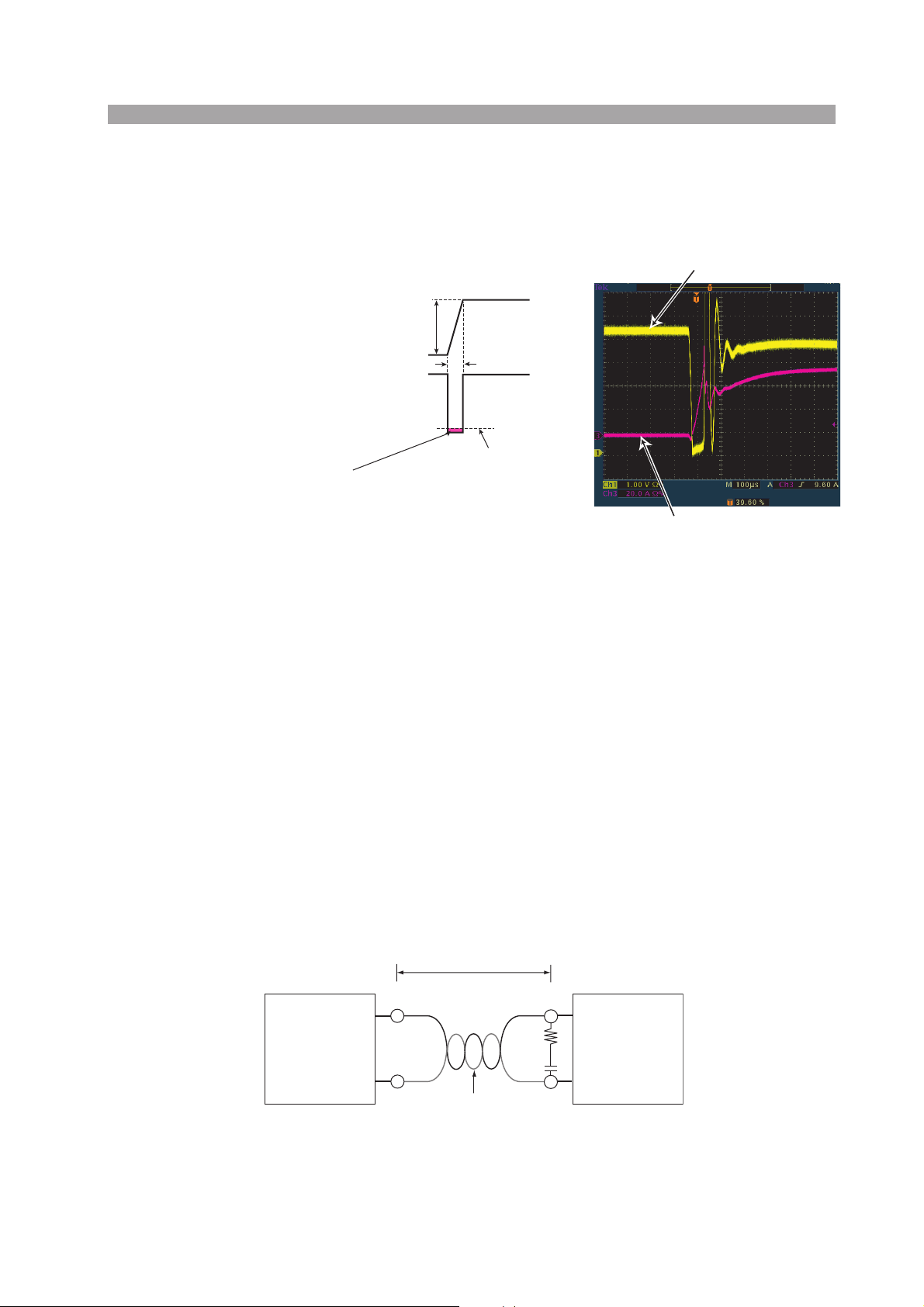
When the value of instantaneous voltage drops under the minimum operating voltage
depends on the generated voltage at the load input terminal, the response of recovery will
be extensively delayed. In such event, the electronic load (PLZ-U) may generate unstable
oscillation or becomes into the hunting operation.
In such condition, the input voltage
may exceed the maximum input voltage and cause damage to the PLZ-U.
Voltage at the load input terminal
Current
Voltage at Load Input Terminal
When the voltage drops under minimum
operating voltage, the electronic load may generate
unstable oscillation or becomes into hunting operation.
ΔI
ΔT
Minimum operating voltage
Current
Example of waveform
Fig. 2-8 Waveform example: Generate unstable oscillation or hunting
operation
You must be careful especially when the slew rate setting is high or switching is performed using large currents through parallel operation.
To prevent problems, connect the PLZ-U and the equipment under test using the
shortest twisted wire possible to keep the voltage caused by inductance between the
minimum operating voltage and the maximum input voltage range or set a low slew
rate.
If the high-speed response operation is not required, decrease the slew rate setting.
In such settings, the value of DI /DT will be decreased, accordingly the generated
voltage will be reduced even the inductance of load wiring can not be reduced.
In the case of DC operation also, the phase delay of the current may cause instability in the PLZ-U control inducing oscillation. In this case also, connect the PLZ-U
and the equipment under test using the shortest twisted wire possible.
If only DC operation is required, a capacitor and a resistor may be connected to the
load input terminal as shown in Fig. 2-9 to alleviate oscillation. In this case, use the
capacitor within its allowable ripple current.
Keep the wire short
+
Equipment
under test
–
Twist
+
R
PLZ-U Series
C
–
Example: R = 10 Ω and
C = 100 μF
Fig. 2-9 Length of wiring
PLZ-U Installation and Preparation 2-13

■ Overvoltage
+
+–+
n
CAUTION
CAUTION
NOTE
• Do not apply voltage exceeding the maximum voltage of 150 VDC to the
load input terminal, as it may cause damage.
The maximum voltage that can be applied to the load input terminal is 150 VDC.
Voltage exceeding the maximum cannot be used. If overvoltage is applied, an alarm
message appears along with an alarm buzzer, and the load is turned off. If this happens, immediately lower the voltage of the equipment under test.
■ Polarity
• If the polarity of the connection is reversed, overcurrent will flow and may
damage the PLZ-U or the equipment under test.
Be sure to match the polarities between the load input terminal and the equipment
under test.
If the polarity is reversed, an alarm message appears along with an alarm buzzer.
Immediately turn off the power to the equipment under test.
• The buzzer sounds when a reverse voltage of approximately 0.6 V or greater is
applied.
Correct connection
Equipment
under test
+
≤ 150 DCV
–
+
PLZ-U Series
–
ncorrect connectio
Equipment
under test
Fig. 2-10 Connect by paying attention to the polarity
PLZ-U Series
–
2-14 Installation and Preparation PLZ-U

2.7.2 Connection to the Load Input Terminal on the Rear Panel
WARNING
CAUTION
• Do not touch the load input terminal while the PLZ-U is turned ON, as it
may lead to electric shock. In addition, be sure to use the load input terminal cover.
• The load input terminals on the front and rear panels are coupled inside
the PLZ-U. A voltage applied to one end will appear at the other end.
• Do not connect equipment to the load input terminals on the front and rear
panels simultaneously, as it can cause damage.
• There is a danger of overheating. Attach crimping terminal to the wire and
use the set of screws that came with the package for connection.
■ Connection procedure of the load input terminal on the rear
panel
1. Turn off the POWER switch.
2.
Check that the output of the equipment under test is off.
3.
Connect the load wire to the load input terminal on the rear panel (Fig.
2-11).
4.
Attach the load input terminal cover on the rear panel. For details on
how to use the terminal cover, see Fig. 2-12 and Fig. 2-13.
5.
Check the polarity of the connection and connect the load wire to the
output terminal of the equipment under test.
Bolt (M6)
Be sure to use the set
of screws provided
with the package.
Crimp terminal
Spring washer (M6)
Nut (M6)
Fig. 2-11 Connection to the load input terminal on the rear panel
PLZ-U Installation and Preparation 2-15
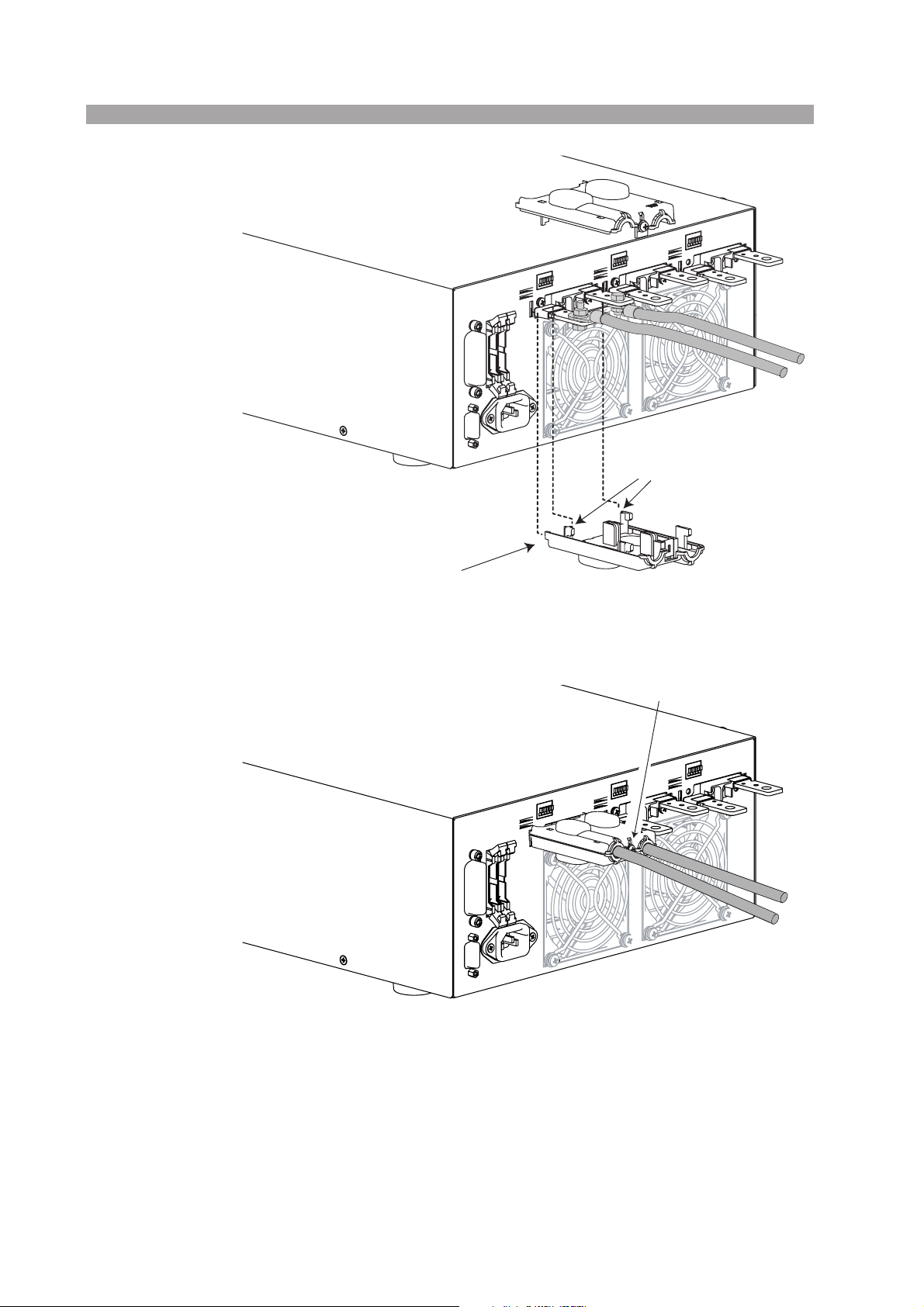
TOP
Align the protrusion on the inside
to the concavity of the load input
terminal
BOTTOM
Insert into the hole in the rear panel
Fig. 2-12 Attachment of the load input terminal cover on the rear panel 1
Align the top and bottom parts
of the terminal cover and screw
them in place.
Check that the cover does
not come off easily.
Fig. 2-13 Attachment of the load input terminal cover on the rear panel 2
2-16 Installation and Preparation PLZ-U
 Loading...