

Kikusui PLZ164W, PLZ334W, PLZ1004W, PLZ664WA, PLZ164WA Quick Reference
Z1-004-802, IB020572
Oct. 2015
PLZ-4W Series
Quick Reference
26
Display
29
LOAD
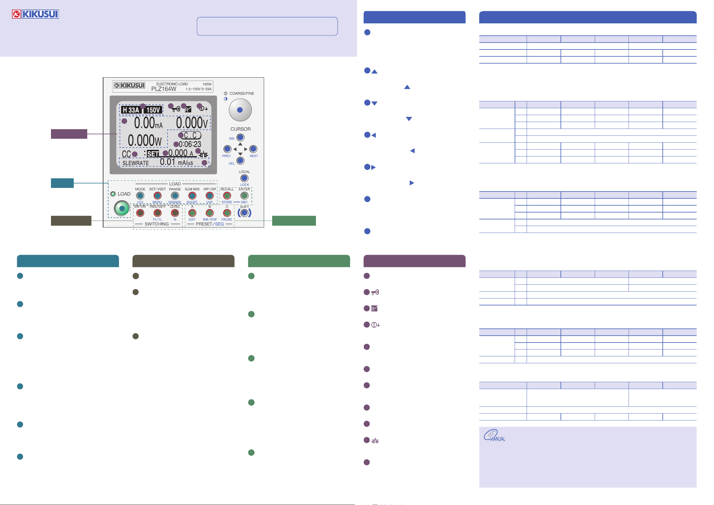
1
SWITCHING PRESET/SEQ
LOAD
1
LOAD key
Turns the load on and off. The LED lights
when the load is on and turns off when the
load is off.
2
MODE key
Sets the operation mode.
+CV (SHIFT + MODE) key
Adds CV to CC or CR mode.
3
SET/VSET key
Sets the fundamental settings (current/
conductance/voltage/power).
MENU (SHIFT + SET/VSET) key
Used to set features and environment
settings, calibrate the PLZ, and display
product information.
4
RANGE key
Sets the range (L/M/H).
VRANGE (SHIFT + RANGE) key
Switches the voltage value range (15 V/150
V).
5
SLEW RATE key
Sets the slew rate value.
SHORT (SHIFT + SLEW RATE) key
Activates or deactivates the short function.
6
OPP/OCP key
Sets the power at which OPP is activated or
the current at which OCP is activated.
UVP (SHIFT + OPP/OCP) key
Sets the voltage at which UVP is activated.
7
8
Th/TL (SHIFT+FREQ/DUTY) key
9
% (SHIFT + LEVEL) key
You can download the most recent manuals from the following website.
http://www.kikusui.co.jp/en
23
22
30
2 3 4 5 6
7 8 9
24 25
27
28
31
32
12 13 14
* Red keys are lighted.
SWITCHING
SW ON key
Turns switching mode on and off.
FREQ/DUTY key
Sets the switching frequency or the duty
ratio.
Sets the switching time (Th: HIGH/TL:
LOW).
LEVEL key
Sets the switching level. The key lights
when the level can be set.
Sets the switching level as a percentage of
the set value (0 % to 100 %).
15
16
18
17
10 11
19
20
21
PRESET/SEQ
10
RECALL key
Recalls the saved panel settings into the
setup memory.
STORE (SHIFT + RECALL) key
Saves the panel settings to the setup memory.
11
ENTER key
Sets various values and releases alarms.
ABC (SHIFT + ENTER) key
Saves the panel settings to the preset
memory. After you press this key, press the
A, B, or C key.
12
A key
Recalls the settings in preset memory A.
When this key is pressed after the ABC key,
it saves the settings.
EDIT (SHIFT + A) key
Displays the sequence editing screen.
13
B key
Recalls the settings in preset memory B.
When this key is pressed after the ABC key,
it saves the settings.
RUN/STOP (SHIFT + B) key
Displays the sequence screen. Starts and
stops sequence execution.
14
C key
Recalls the settings in preset memory C.
When this key is pressed after the ABC key,
it saves the settings.
PAUSE (SHIFT + C) key
Temporarily stops or restarts sequences.
Miscellaneous
15
Rotary knob
Changes the settings. Press the knob to
switch between coarse and fine adjustment.
Contrast (SHIFT + knob)
Adjusts the contrast of the display.
16
key
The up key.
INS (SHIFT+ ) key
Adds a step (sequence function).
17
key
The down key.
DEL (SHIFT+ ) key
Deletes a step (sequence function).
18
key
The left key.
PREV (SHIFT+ ) key
Returns to the previous screen.
19
key
The right key.
NEXT (SHIFT+ ) key
Switches to the next screen.
20
LOCAL key
Switches from remote mode to local mode.
LOCK (SHIFT + LOCAL) key
Enables or disables the key lock.
21
SHIFT key
Enables the functions displayed in blue
below the keys.
Display
22
Range display
Displays the current and voltage ranges.
23
(key icon)
Appears when the key lock is enabled.
24
(remote icon)
Appears during external communication.
25
(COARSE/FINE icon)
Indicates whether the rotary knob is set to
coarse or fine adjustment.
26
Measured value display
Indicates the measured values (current,
voltage, and power).
27
Operation status display
Displays the current operation mode.
28
Elapsed time display
Displays the amount of time that has
elapsed since the load was turned on.
29
Operation mode display
Displays the set operation mode.
30
Setting display
Displays the set value.
31
(short icon)
Appears when the short function is being
executed.
32
Multi display
Displays various settings and statuses.
Main Specications
Ratings
Model PLZ164W PLZ334W PLZ1004W PLZ164WA PLZ664WA
Operating voltage (DC)
Current 33 A 66 A 200 A 33 A 132 A
Power 165 W 330 W 1000 W 165 W 660 W
1.
Minimum voltage at which the current starts flowing to the PLZ-4W is approximately 0.3 V.
2.
The minimum operating voltage (including the voltage drop due to the wire inductance component) in switching mode
increases by 0.15 V per 1 A/μs at slew rate settings greater than 5 A/μs.
3.
The minimum operating voltage (including the voltage drop due to the wire inductance component) in switching mode
increases by 0.3 V per 1 A/μs at slew rate settings greater than 5 A/μs.
Constant Current Mode (CC)
Model
Operating range H 0 A to 33 A 0 A to 66 A 0 A to 200 A 0 A to 33 A 0 A to 132 A
Accuracy of setting H, M ± ( 0.2 % of set + 0.1 % of f.s
Input voltage
3
variation
1.
Full scale of H range
2.
Vin: Input terminal voltage of Electronic Load
3.
When the input voltage is varied from 1.5 V to 150 V at a current of rated power/150 V.
Constant Resistance Mode (CR)
Model
Operating range
Accuracy of setting2H, M ±(0.5 % of set3 + 0.5 % of f.s4 ) + Vin5 /500 kΩ
1.
Conductance [S] = Input current [A]/input voltage [V] = 1/resistance [Ω]
2.
Converted value at the input current. At the sensing point.
3.
set = Vin/Rset
4.
Full scale of H range
5.
Vin: Input terminal voltage of Electronic Load
Constant Voltage Mode (CV)
Model
Operating range H 1.5 V to 150 V 0 V to 150 V
Accuracy of setting1--- ±(0.1 % of set + 0.1 % of f.s)
Input current variation2--- 12 mV
1.
At the sensing point during remote sensing under the operating range of the input voltage.
2.
With respect to a change in the current of 10 % to 100 % of the rating at an input voltage of 1.5 V (during remote sensing).
Constant Power Mode (CP)
Model
Operating range H 16.5 W to 165 W 33 W to 330 W 100 W to 1000 W 16.5 W to 165 W 66 W to 660 W
Accuracy of setting
1.
M range applies to the full scale of H range.
General
Model PLZ164W PLZ334W PLZ1004W PLZ164WA PLZ664WA
Input voltage range 100 Vac to 240 Vac
Input frequency range 47 Hz to 63 Hz
Power consumption 80 VA max. 90 VA max. 160 VA max. 450 VA max. 1500 VA max.
Chapter 3
Sequence Function
6.6
Remote Sensing Function
6.7
External Control
6.8
In the appendix, there are explanations of the operation modes and the operating area and a sequence program creation table.
For information about remote control, see the communication interface manual (contained in the accompanying CD-ROM).
1
Range
Range
1
Range
Range
PLZ164W PLZ334W PLZ1004W PLZ164WA PLZ664WA
M 0 A to 3.3 A 0 A to 6.6 A 0 A to 20 A 0 A to 3.3 A 0 A to 13.2 A
L 0 A to 330 mA 0 A to 660 mA 0 A to 2 A 0 A to 330 mA 0 A to 1.32 A
L ± ( 0.2 % of set + 0.1 % of f.s )
H 2 mA 4 mA 10 mA 2 mA 8 mA
M 2 mA 4 mA 10 mA 2 mA 8 mA
L 0.1 mA 0.2 mA 0.6 mA 0.1 mA 0.4 mA
PLZ164W PLZ334W PLZ1004W PLZ164WA PLZ664WA
H 22 S to 400 μS 44 S to 800 μS
M 2.2 S to 40 μS 4.4 S to 80 μS
L 0.22 S to 4 μS 0.44 S to 8 μS 1.33332 S to 24 μS 0.22 S to 4 μS 0.88 S to 16 μS
L ± (0.5 % of set
PLZ164W PLZ334W PLZ1004W PLZ164WA PLZ664WA
L 1.5 V to 15 V 0 V to 15 V
PLZ164W PLZ334W PLZ1004W PLZ164WA PLZ664WA
M 1.65 W to 16.5 W 3.3 W to 33 W 10 W to 100 W 1.65 W to 16.5 W 6.6 W to 66 W
L 0.165 W to 1.65 W 0.33 W to 3.3 W 1 W to 10 W 0.165 W to 1.65 W 0.66 W to 6.6 W
--- ±(0.6 % of set + 1.4 % of f.s1)
(90 Vac to 250 Vac) single phase, continuous
1.5 V to 150 V
2
133.332 S to 2.4 mS
13.3332 S to 240 μS
0 V to 150 V
1
) + Vin2 /500 kΩ
22 S to 400 μS 88 S to 1.6 mS
2.2 S to 40 μS 8.8 S to 160 μS
3
+ 0.5 % of f.s)
100 Vac to 120 Vac/200 Vac to 240 Vac
(90 Vac to 132 Vac/180 Vac to 250 Vac)
single phase
3
The User’s Manual (contained in the accompanying CD-ROM)
contains the following additional information.
For First Time Users
Monitor Signal Output
6.9
Parallel Operation
6.10
Maintenance
8.1
Confirming Status of the Fuse
8.2
Calibration
8.3
Malfunctions and Causes
8.4
Chapter 9
Specifications

Turing on the Load
ABC Preset Memory
Other Settings
Make sure that the load is off.
1
Select an operation mode.
2
Press MODE to switch between modes.
Select a current range.
3
Press RANGE to switch between ranges.
Select a voltage range.
4
Press VRANGE (SHIFT + RANGE) to switch between ranges.
Set the current, voltage, conductance, or power value.
5
Press SET/VSET to select a value, and set the value using the rotary
knob.
Turn on the load.
6
Press LOAD. You can change the setting (current, voltage,
conductance, or power) while the load is on.
• +CV Mode
You can press +CV (SHIFT + MODE) in CC mode or CR mode to add CV.
You can add CV even while the load is on.
The value that you can set changes when you press SET/VSET.
Protection Functions
The electronic load has seven kinds of protection functions. When a
protection function is activated, an alarm occurs.
You can set the value to detect for the OCP, OPP, and UVP functions.
You can choose the action (load off or limit) that is performed by the OCP
and OPP functions from the menu.
You can stop an alarm by pressing ENTER. The alarm will be activated
again if its cause has not been eliminated.
Overcurrent Protection (OCP)
Activated at the specified value or at 110% of the maximum current.
To set the value, press OPP/OCP, and turn the rotary knob. Press OPP/
OCP to switch between OCP and OPP.
Overvoltage Protection (OVP)
Activated at 110 % of the maximum input voltage.
Overpower Protection (OPP)
Activated at the specified value or at 110 % of the maximum power.
To set the value, press OPP/OCP, and turn the rotary knob. Press OPP/
OCP to switch between OCP and OPP.
Undervoltage Protection (UVP)
Activated when the voltage goes below the set value.
To set the value, press UVP, and turn the rotary knob. If you do not want
to use UVP, select OFF.
Reverse-Connection Protection (REV)
Activated when reverse voltage is applied to the load input terminals.
Turn off the power of the DUT within 30 seconds.
If reverse voltage is detected when you are using the PLZ164WA/
PLZ664WA in a test where a DC power supply is connected in series
with the DUT, see “When the DC power supply and the DUT are
connected in series, and turning on/off of the DUT” (p. 5-5) in the User’s
Manual.
Overheat Protection (OHP)
Activated when the temperature of the internal power unit exceeds 95°C.
Alarm Input Protection
Activated when a low-level signal is applied to the ALARM INPUT pin of
the J1 terminal.
The preset memory can be used to save and recall current, resistance,
voltage, and power values.
• Saving
Switch to the operation mode that you want to save,
1
and set its ranges and value.
Press ABC.
2
The A, B, and C keys blink.
Press the key that corresponds to the memory that you
3
want to save to.
The key will light. After you change the settings, the key light will turn off.
• Recalling
Switch to the operation mode that you want to load values into, and press
the key that corresponds to the memory that you want to recall (A, B, or
C).If Memory is set to SAFETY, press ENTER.
Setup Memory
You can use the setup memory to save and recall protection-function
activation values, ABC setup memory settings, menu settings, and so on.
• Saving
Press STORE (SHIFT + RECALL).
1
Use the rotary knob to select the memory no. that you
2
want to save to.
Enter a memo.
3
Press ENTER.
4
• Recalling
Press RECALL.
1
You cannot recall settings while the load is on.
Use the rotary knob to select the memory no. that you
2
want to recall.
Press ENTER.
3
Switching Function
You can use this function to set two load current values and switch
between them.
Set the switching level and the switching interval.
• Switching Level
Press LEVEL to select a value, and set the value using the rotary knob.
Press % (SHIFT + LEVEL) to set the level as a percentage.
• Switching Interval
You can set the switching interval by specifying a frequency and duty
ratio or by specifying an amount of time.
Setting a Frequency and Duty Ratio
Use the FREQ/DUTY key and the rotary knob to set the values. Press
FREQ/DUTY to switch between the frequency and the duty ratio.
Setting a Time
Use the Th/TL (SHIFT+FREQ/DUTY) key and the rotary knob to set a
time. Press Th/TL (SHIFT+FREQ/DUTY) to switch between the high
and low sides of the switching time.
Functions Useful for Battery Discharge Testi
• Elapsed Time Display (Count Time)
You can measure the time from the start of discharge to the cutoff
voltage. You can enable the elapsed time display from the menu.
• Auto Load-Off Timer (Cut Off Time)
You can use this function to turn the load off after a specified amount of
time has passed since the start of discharge and measure the closed
circuit voltage immediately before the load is turned off. You can set the
auto load-off timer from the menu.
ng
• Soft Start
In CC mode and CR mode, you can use this function to raise the
electronic load’s current gradually. This is useful in cases such as when
voltage application begins at the same time that the load is turned on
and when voltage is applied while the load is on and there is no load
input.
You can enable the soft start function from the menu.
• Locking the Electronic Load
You can press LOCK (SHIFT + LOCAL) to lock the electronic load and
disable all operations other than the turning on and off of the load,
sequence execution, and memory recall. To release the lock, press and
hold LOCK (until you hear a confirmation sound).
• Short Function
You can use this function to specify the maximum current value (CC
mode) or the minimum resistance value (CR mode) instantaneously.
To activate the short function, press SHORT (SHIFT + SLEW RATE) while
the load is on. Press SHORT again to deactivate the short function.
• Response Speed
This is the speed at which the input current and voltage values are
detected and controlled through negative feedback. You can set the
response speed in CC mode and CR mode.
You can set the response speed from the menu.
When you operate an electronic load in parallel or at high speeds (with
the switching function for example), refer to “Notes about Parallel and
High-Speed Operation” on the CD-ROM to set the response speed.
• Slew Rate Setting
When the current changes rapidly because you are using the switching
function or for some other reason, set the slew rate to determine the rate
at which the current is changed.
Press SLEW RATE, and set the value using the rotary knob.
• Resetting to the Factory Default Settings
While holding ENTER, turn on the power switch. The contents of the
memory are deleted.
Menu Settings
Make sure that the load is off.
1
Press MENU (SHIFT + SET/VSET).
2
The menu screen appears.
Use the cursor keys and ENTER to select the item that
3
you want to set.
Press PREV (SHIFT + ) to return to the previous screen.
1
Menu 1
1.Setup 1.Function Soft Start 1ms, 2ms, 5ms, 10ms, 20ms, 50ms,
2.Configuration
4.Model Info
1.
In menu 1, 3. Calibration is for calibrating the electronic load. For details, see the User’s Manual.
2.
The Configuration settings are not applied until you turn the power off and then on again.
3.
This is information about the electronic load. It cannot be changed.
3
Menu 2 Item Settings Description
100ms, 200ms
Count Time OFF, ON Elapsed time display
2.Protect Action OCP LOAD OFF, LIMIT Operation to be performed when OCP is activated
OPP LOAD OFF, LIMIT Operation to be performed when OPP is activated
3.Memory ABC Preset Memory Recall DIRECT, SAFETY Method for recalling the preset memory
4.Cut Off Time OFF, 0:00:01 to 999:59:59 Auto load-off timer
5.Response --- 1/1, 1/2, 1/5, 1/10 Response speed
2
1.Master/Slave Operation Master, Slave Master/slave switching
Parallel -, 2, 3, 4, 5 Number of devices operating in parallel
Booster -, 1, 2, 3, 4 Number of boosters connected in parallel
2.Power On Load On OFF, ON State of the load when the power switch is turned on
Key Lock OFF, ON Key lock
3.Interface Control GPIB, RS232C, USB Interface setting
GPIB Address 1 to 30 GPIB address
RS232C Baudrate 2400bps, 4800bps, 9600bps,
19200bps
3
, Stop Data: 8
Data
Stop: 1, 2
3
Parity
Ack OFF, ON Acknowledgment
3
USB
4.External Control OFF, V, R, Rinv External control for the CC, CR, and CP modes
LoadOn IN LOW, HIGH External control logic setting for turning the load on and off
(MODEL) --- PLZxxxx Model name
VERSION SUB --- x.xx Firmware version
VERSION MAIN --- x.xx ROM version
VID 0x0B3E Vendor ID
PID xxxxxx Product ID
S/N xxxxxxxx Serial number
NONE Parity (fixed at none)
Use the rotary knob to select a value.
4
Press MENU (SHIFT + SET/VSET).
5
The menu screen will close and the settings that you configured will
be applied. The Configuration settings are not applied until you turn
the power off and then on again.
Soft start time
Baud rate
Data length (fixed at 8 bits) and the stop bit
 Loading...