

Kikusui PFX2515 Operation Manual

PART NO. Z1-005-772, IB025063
Jul. 2015
PFX2512
General
Description
Installation and
Preparation
Operations
Specification
1
2
3
4
Volt / Thermometer Unit
OP02-PFX
5
7
App.
Operation Manual
Charge/Discharge System
Charge/Discharge System Controller
PFX2500 Series
Features of the digital
CC/CV contr
ol
Description of the Function
Connecting to a Bias Power Supply
Reference Data
Troubleshooting
Meintenance
Marked Products
PFX2512_CE 1

Thank you for purchasing the PFX2512 Charge / Discharge System
About this manual
Controller.
Dedicated application software enables you to set the conditions
of the battery charge/discharge characteristics tests, execute the
tests, and analyze the test results on a PC.
It is required to use the application software "BPChecker3000" for
the operation of the PFX2512, Charge/Discharge System
Controller.
The BPChecker3000 application software are sold separately.
Trademarks
Microsoft and Windows are registered trademarks of Microsoft
Corporation in the United States and/or other countries.
Other company names and product names used in this manual are
generally trademarks or registered trademarks of the respective
companies.
Copyrights
The contents of operation manual may not be reproduced, in
whole or in part, without the prior consent of the copyright holder.
The specifications of this product and the contents of operation
manual are subject to change without prior notice.
This manual is intended for first-time users of this product. It
provides an overview of the product and notes on usage. It also
explains how to configure the product, operate the product,
perform maintenance on the product, and so on.
Read this manual thoroughly to use the functions of the product
effectively. You can also review this manual when you are
confused about an operation or when a problem occurs.
After reading, always keep the manual nearby so that you may
refer to it as needed.
If you find any misplaced or missing pages in operation manual, it
will be replaced.
If the operation manual gets lost or soiled, a new copy can be
provided for a fee. In either case, please contact Kikusui
distributor/agent, and provide the “Kikusui Part No.” given on the
cover page.
Operation manual has been prepared with the utmost care;
however, if you have any questions, or note any errors or
omissions, please contact Kikusui distributor/agent.
Product firmware versions
This manual applies to products with firmware versions 1.XX.
When contacting us about the product, please provide us with:
The model (marked in the top section of the front panel)
Firmware version (See 50 page)
The serial number (marked in the bottom section of the rear
panel)
© 2009 Kikusui Electronics Corporation
How to read this manual
This manual is designed to be read from beginning to end. We
recommend that you read it thoroughly before using this product
for the first time.
Related manuals
For details on the BPChecker3000, see the corresponding
operation manual.
For details on the PWR series Regulated DC Power supplies, PAS
series Regulated DC Power supplies, and PLZ-4W series Electronic
Loads, see the corresponding operation manual.
Intended readers of this manual
This manual is intended for users of the product or persons
teaching other users on how to operate the product.
The manual assumes that the reader has knowledge about
electrical safety testing.
2 PFX2512_CE
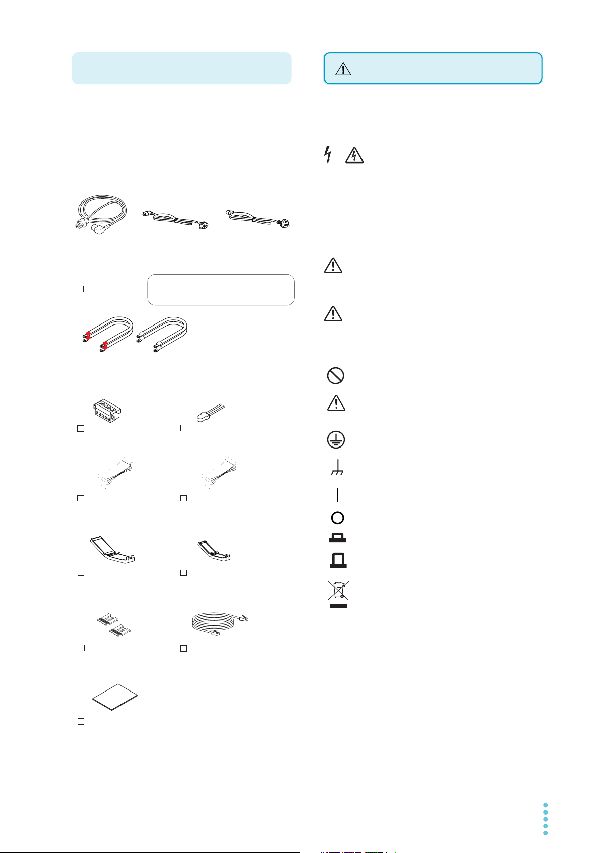
Checking the Package Contents
or
or
Power cord (1 pc.)
Operation manual
(This manual, 1 copy)
LAN cable (1 pc.)
Straight type
[91-80-9230]
[ ]
Cable with crimp terminal (4 pcs.)
Red (2 pc.) : 91-80-7557
White (2 pc.) : 91-80-7522
Thermistor (1 pc.)
[38-00-0160]
Sensing connector (1 pc.)
[84-61-7705]
26-conductor flat cable (1 pc.)
(Dc Power Supply I/F cable)
[83-22-6050]
20-conductor flat cable (1 pc.)
(Electronic Load I/F cable)
[91-80-6136]
Lock lever
(2 pcs.)
[83-06-5060]
The power cord that is provided varies
depending on the destination for the product
at the factory-shipment.
Rating: 125 Vac/ 10 A
PLUG: NEMA5-15
[85-AA-0003]
[85-AA-0005]
Rating: 250 Vac/ 10 A
PLUG: CEE7/7
[85-10-0790]
Rating: 250 Vac/ 10 A
PLUG: GB1002
Ferrite core for
26-conductor flat cable (1 pc.)
[96-01-0260]
Ferrite core for
20-conductor flat cable (1 pc.)
[96-01-0250]
Safety Symbols
When you receive the product, check that all accessories are
included and that the accessories have not been damaged during
transportation.
If any of the accessories are damaged or missing, contact your
Kikusui agent or distributor.
We recommend that you keep all packing materials, in case the
product needs to be transported at a later date.
For the safe use and safe maintenance of this product, the
following symbols are used throughout operation manual and on
the product. Note the meaning of each of the symbols to ensure
safe use of the product. (Not all symbols may be used.)
or
Indicates that a high voltage (over 1 000 V) is used here.
Touching the part causes a possibly fatal electric shock. If
physical contact is required by your work, start work only
after you make sure that no voltage is output here.
DANGER
Indicates an imminently hazardous situation which, if
ignored, will result in death or serious injury.
WAR NING
Indicates a potentially hazardous situation which, if
ignored, could result in death or serious injury.
CAUTION
Indicates a potentially hazardous situation which, if
ignored, may result in damage to the product and other
property.
Indicates a prohibited act.
Indicates a warning, caution, or danger. When this
symbol is marked on the product, see the relevant
section in this manual.
Protective conductor terminal.
Chassis (frame) terminal.
On (supply)
Off (supply)
In position of a bi-stable push control
Out position of a bi-stable push control
Indicates that this product conforms to the
requirements of the Waste Electrical and Electronic
Equipment Directive.
In the EU, this product cannot be disposed of as
domestic household waste.
When disposing of this product, follow the Waste
Electrical and Electronic Equipment (WEEE)
Directive.
In areas outside of the EU, dispose of it as per the
instructions of the local authorities.
PFX2512_CE 3
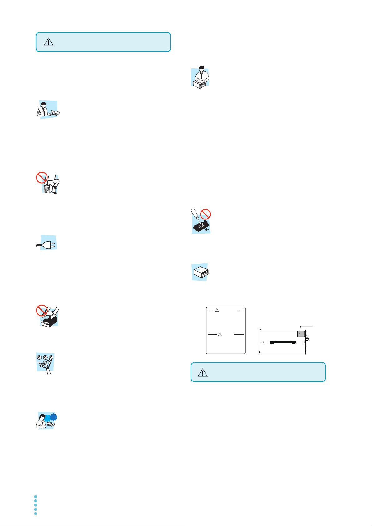
The following safety precautions must be observed to avoid fire
Safety Precautions
Ope
rat
ion
Manual
Line
Voltage
G
N
L
Check?
WARNING
㆙ࠉ࿌
本製品のカバーは、絶対に取り外しては
いけません。
内部の点検は当社が認めたサービスマン
に委託してください。
主電源コード及び負荷線の取り扱いは、
必ず主電源プラグを抜いてから行って
ください。
DO NOT REMOVE COVERS.
NO OPERATOR SERVICEABLE
PARTS INSIDE.
REFER SERVICING TO QUALIFIED
SERVICE PERSONNEL.
UNPLUG THE MAINS SUPPLY
CORD BEFORE HANDLING
THE CORD OR LOAD WIR ES.
Label
PFX2500 Series
Top panel
Precautions When Moving the Product
hazards, electric shock, accidents, and device failures. Keep them
in mind and make sure to observe them.
Using the product in a manner that is not specified in this manual
may impair the protection functions provided by the product.
Users
• This product must be used only by qualified personnel who
understand the contents of this operation manual.
• If an unqualified personnel is to use the product, be sure the
product is handled under the supervision of qualified personnel
(those who have electrical knowledge). This is to prevent the
possibility of personal injury.
Purpose of use
• Never use the product for purposes other than the product’s
intended use.
• This product is not designed or manufactured for general home
or consumer use.
Input power
• Use the product within the rated input line voltage range.
• For applying power, use the power cord provided. For details,
see the respective page in this manual.
• The product is an equipment of IEC Overvoltage Category II
(energy-consuming equipment supplied from the fixed
installation).
outlet. Make sure the product is not used until it is completely
repaired.
• Do not disassemble or modify the product. If you need to
modify the product, contact your Kikusui distributor or agent.
Maintenance, Inspection and Calibration
• To maintain the performance and safety of the product, we
recommend periodic maintenance, inspection, cleaning, and
calibration.
• To prevent electric shock, be sure to unplug the product before
carrying out maintenance or inspection. Do not remove the
external cover.
• Check periodically that there are no tears or breaks in the power
cord.
• If the panel needs cleaning, gently wipe it using a soft cloth
with water-diluted neutral detergent. Do not use volatile
chemicals such as benzene or thinner.
• This product is calibrated before shipment. To maintain the
product’s performance, we recommend periodic calibration. To
have your product calibrated, contact your Kikusui agent/
distributor.
Service
• Kikusui service engineers will perform internal service of the
product. If the product needs adjustment or repairs, contact
your Kikusui distributor or agent.
Warning label
There is a warning label affixed to the product. If this label tears or
falls off, replace with a new label. If you need a new label, contact
your Kikusui agent or distributor.
Cover
• Some parts inside the product are hazardous. Do not remove
the external cover.
Grounding
• The product is IEC Safety Class I equipment (equipment with a
protective conductor terminal). To prevent electric shock, be
sure to connect the protective conductor terminal of the
product to electrical ground (safety ground).
Operation
• Before use, visually check for problems in the power cord,
discharge gun, and high-voltage cable. When checking for
these problems, remove the power cord plug from the outlet.
• If you notice a malfunction or abnormality in the product, stop
using it immediately, and remove the power cord plug from the
4 PFX2512_CE
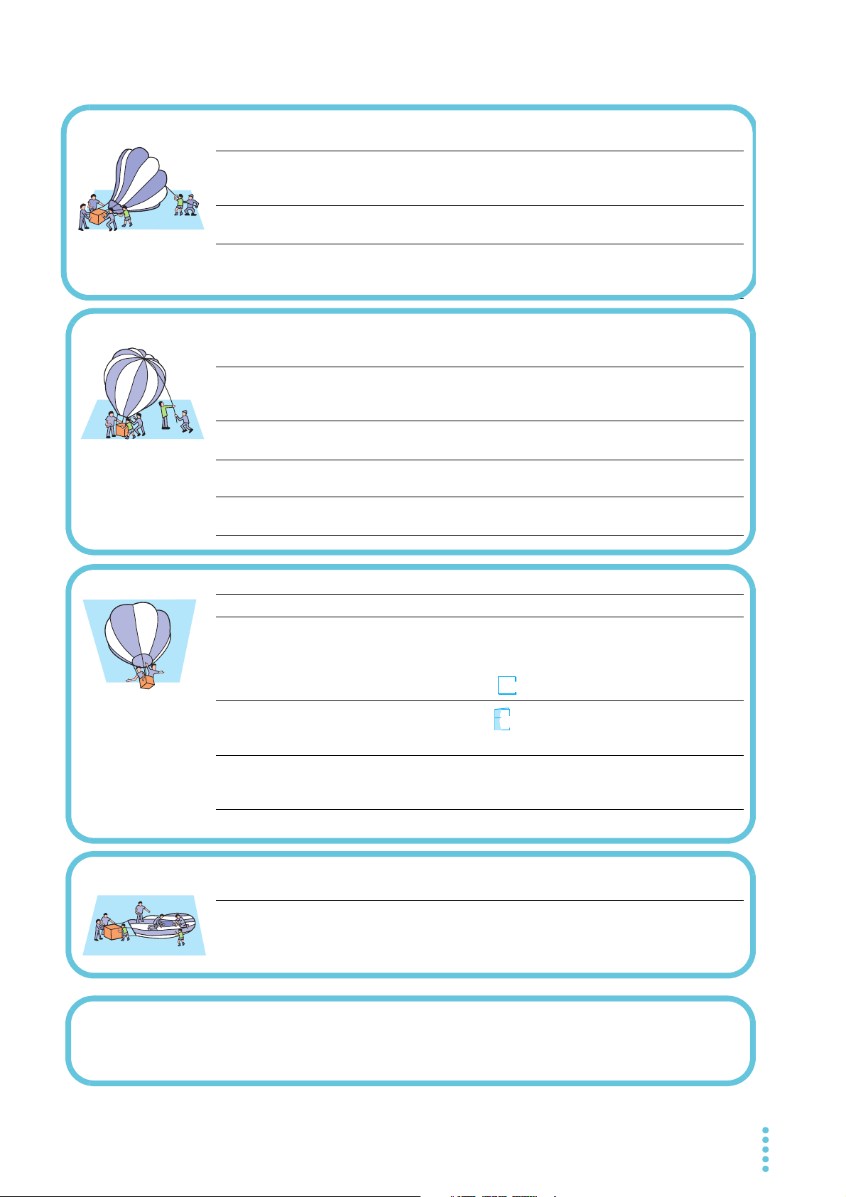
Note the following points when moving the product to the
installation location or when transporting the product.
•Turn the POWER switch off.
Moving the product with the POWER switch turned on may
cause electric shock or damage to the product.
• Remove all wiring.
Moving the product with the cables connected may cause wires
to break or injuries due to the product falling over.
• When transporting the product, be sure to use the original
packing materials.
Otherwise, damage may result from vibrations or from the
product falling during transportation.
• Be sure to include this manual.

Be sure observe the following precautions when installing the
Precautions Concerning Installation
Notations used in this manual
WARNING
CAUTION
?
Help
Memo
product.
• Do not use the product in a flammable atmosphere.
To prevent the possibility of explosion or fire, do not use the
product near alcohol, thinner, or other combustible materials,
or in an atmosphere containing such vapors.
• Avoid locations where the product is exposed to high
temperature or direct sunlight.
Do not install the product near a heater or in areas subject to
drastic temperature changes.
Operating temperature range : 0 °C to 40 °C (32 °F to 104 °F)
Storage temperature range : -10 °C to 60 °C (14 °F to 140 °F)
• Avoid humid environments.
Do not install the product in high-humidity locations such as
near a boiler, humidifier, or water supply.
Operating humidity range: 20 %rh to 85 %rh (no condensation)
Storage humidity range : 0 %rh to 90 %rh (no condensation)
Condensation may form even within the operating humidity
range. If this happens, do not use the product until the
condensation dries up completely.
• Be sure to use the product indoors.
This product is designed for safe indoor use.
• Provide adequate space around the power cord plug.
Do not insert the power cord plug into an outlet that is not
easily accessible. Do not place objects near the power cord plug
that would make it difficult to access.
• Do not install the product in a corrosive atmosphere.
Do not install the product in a corrosive atmosphere or in
environments containing sulfuric acid mist, etc. This may cause
corrosion of various conductors or reduce the quality of the
connector contacts inside the product, and this could lead to
malfunction, failure, and possibly fire.
• Do not install the product in a dusty location.
Dust accumulation can lead to electric shock or fire.
• Do not use the product in a poorly ventilated location.
Provide adequate space around the product for air to circulate
around it.
• Do not place objects on top of the product.
Placing heavy objects on top of the product may cause
malfunction.
• Do not install the product on an inclined surface or in a location
subject to vibrations.
The product may fall or tip over and cause damage and injury.
• Do not use the product in a location subject to strong magnetic
or electric fields or in a location where the input power supply
signal contains large amounts of distortion or noise.
Doing so may cause the product to malfunction.
• Use the product in an industrial environment.
This product may cause interference if used in residential areas.
Such use must be avoided unless the user takes special
measures to reduce electromagnetic emissions to prevent
interference to the reception of radio and television broadcasts.
• The PFX2512 Charge / Discharge System Controller is also
referred to as the PFX2500 series, PFX2500, or PFX2512 in this
manual.
• The BPChecker3000 application softwear is also referred to as
the BPChecker3000 in this manual.
• The PWR series Regulated DC Power supply is also referred to as
the PWR series in this manual.
• The PAS series Regulated DC Power supply is also referred to as
the PAS series in this manual.
• The PLZ-4W series Erectronic Load is also referred to as the PLZ4W series in this manual.
• The OP02-PFX Volt / Thermometer Unit is also referred to as the
OP02-PFX in this manual.
• “PC” in this manual is a generic term for personal computers
and workstations.
• The screen captures used in this manual may differ from the
actual screens that appear on the PFX2512. The screen captures
are merely examples.
• The following markings are used in this manual.
Indicates a potentially hazardous situation which, if
ignored, could result in death or serious injury.
Indicates a potentially hazardous situation which, if
ignored, may result in damage to the product or other
property.
Indicates information that you should know.
See
Indicates reference to detailed information.
Ope
Indicates reference to detailed information operation manual.
Indicates reference to detailed information help file.
Indicates useful information.
PFX2512_CE 5

Contents
5
Volt / Thermometer
Unit
1
2
About this manual 2
Checking the Package Contents 3
Safety Symbols 3
Safety Precautions 4
Precautions When Moving the Product 4
Precautions Concerning Installation 5
Notations used in this manual 5
Search by Topic7
Charge / Discharge System Controller
PFX2512 8
General Description
Product Overview 12
System Configuration 14
Applied DC Power Supplies and Electronic Loads
16
Options 19
Installation and
Preparation
Appe
ndix
(Option)
Attaching of the Volt / Thermometer Unit 76
Preparation of the DUT (battery) Connection 78
Connecting the DUT (battery) 81
Volt / Thermometer Unit OP02-PFX Specifications
82
A Features of the Digital CC/CV
Control88
B Description of the Function 90
C Connecting a Bias Power Supply
93
D Reference Data 94
E Troubleshooting 95
F Maintenance 99
INDEX 101
3
4
Connecting the Power Cord 22
Connection and Setting of the Each Equipment 24
Connecting with the DC Power Supply 27
Connecting with the Electronic Load 29
Using BPChecker3000 to Control the PFX2512 32
Setting the DC Power Supply 38
Setting the Electronic Load 39
Setting the PFX2512 42
Preparation of the DUT (battery) Connection 44
Connecting the DUT (battery) 47
Operations
Turning On and Off of the Power Supply 50
Panel Operation 52
Outline of the External Control 52
Protection Functions and Alarms 54
Setting the Model ID 56
Test Procedure 57
Specification
PFX2512 Functional Specifications 60
PFX2512 Electrical Specifications 67
6 PFX2512_CE
Search by Topic
To solve problems
See ”Troubleshooting” on page 95.
• What accessories are included in the
package?
➔”Checking the Package Contents”
p.3
• How do I know the appropriate system
configuration for charge / discharge
testing's?
➔”Applied DC Power Supplies and
Electronic Loads”
p.16
• What type of cables are required for
connecting to the DUT (batteries) ?
➔”Preparation of the DUT (battery)
Connection”
p.44
• What is the system requirement of the PC
for performing the charge and discharge
testing ?
➔”Product Overview”
p.12
• Where do I find the sample of system
configuration for the charge and discharge
testing specified with the wiring instruction ?
➔”Connection and Setting of the Each
Equipment”
p.24
• How do I set up the connecting system
combined with the power supply and the
Electronic load ?
➔”Setting the Model ID”
p.56
• How do I set the protection function for the
DUT (batteries) ?
➔”Setting the DC Power Supply”
”Setting the Electronic Load”
p.38
p.39
• How do I insert an option board?
➔”Attaching of the Volt / Thermometer
Unit”
p.76
• How do I use the LAN interface to control
the PFX2512 remotely?
➔“Using BPChecker3000 to Control the
PFX2512”
p.32
• How do I operate from the front panel ?
➔”Panel Operation”
p.52
• How do I know the version of firmware ?
➔”Turning on of the power switch”
p.50
• How do I know the operation in detail for
controlling from the PC by using the
application software ?
➔BPChecker3000 is sold separately.
See the help file on the BPChecker3000
CD-ROM.
Io Config, Test Condition Editor,
Test Executive, Graph Viewer
-
• Where do I find the detailed operation of
the connected power supplies and the
Electronic loads?
➔
PWR Series, PAS Series, PLZ-4W Series
-
• How do I perform discharge tests with
voltages that are lower than the discharge
minimum operating voltage?
➔“Connecting to a Bias Power Supply”
p.93
• How should I clean the product and the dust
filter?
➔”Cleaning the dust filter”
p.99
Preparation
Setup
Operation
?
Help
Ope
Maintenance
PFX2512_CE 7
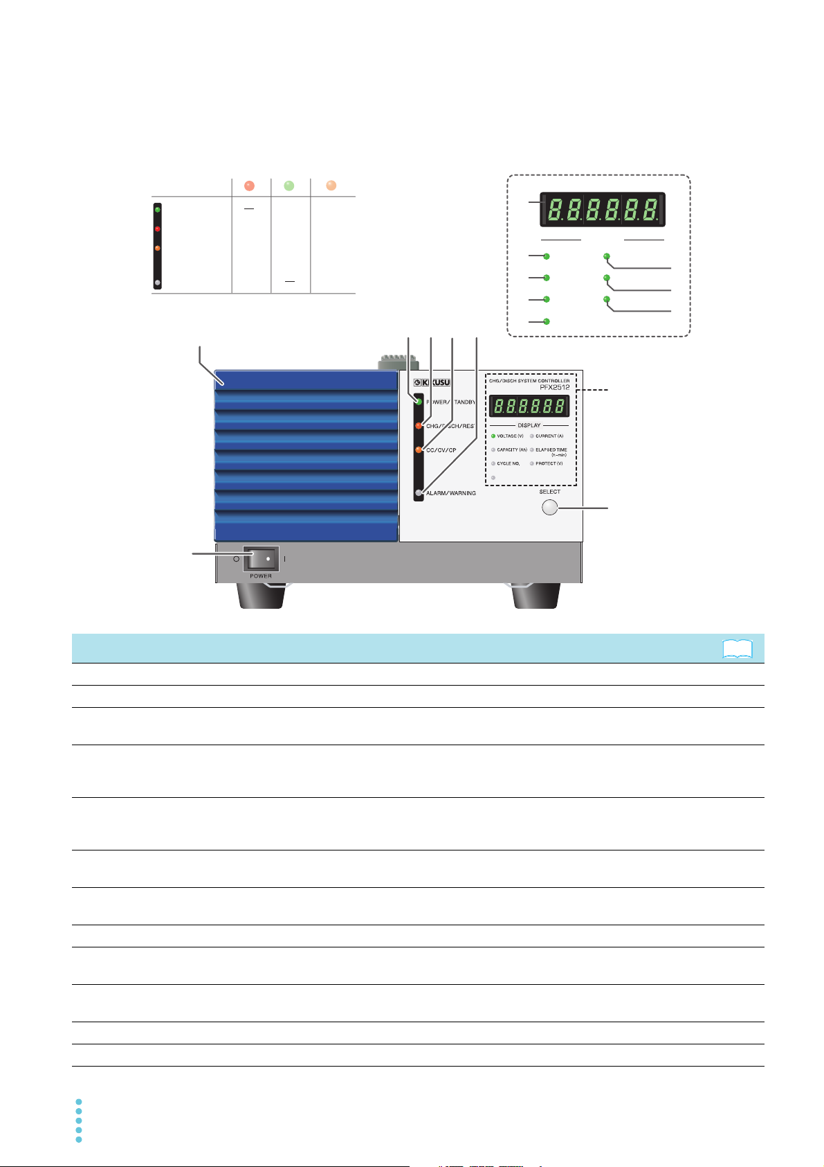
Charge / Discharge System Controller PFX2512
POWER/STANDBY POWER STANDBY
CHG
/
DISCH/REST CHG DISCH REST
CC
/CV/
CP CC CV CP
ALARM
/
WARNING ALARM WARNING
Red
The color of status indication LED and the operation satatus
Green Orange
See
Front panel
Status indication
7
DISPLAY
VOLTAGE (V)CURRENT (A
8
)
CAPACITY (Ah
9
10
2
345 6
14
ADDRESS
CYCLE NO.
ADDRESS
ELAPSED TIME
(h
PROTECT (V
Status indication
)
11
)
-
min
12
)
13
15
1
No. Name Func tion
POWER switch Turns on / off of the power. p.50
1
Air inlet (Louver ) Intake for air circulation to cool down of the internal components.
2
POWER/STANDBY LED
3
CHG/DISCH/REST LED
4
CC/CV/CP LED
5
ALARM/WARNING LED
6
Display
7
VOLTAGE (V) LED It Illuminates when the voltage value is displayed. (when it is selected by the SELECT key) p.52
8
CAPACITY (Ah) LED
9
CYCLE NO. LED
10
CURRENT (A) LED It Illuminates when the current value is displayed. (when it is selected by the SELECT key) p.52
11
ELAPSED TIME (h-min) LED It Illuminates when the elapsed time is displayed. (when it is selected by the SELECT key) p.52
12
8 PFX2512_CE
The POWER LED (Green) Illuminates when the test can be executed. The STANDBY LED
(Orange) Illuminates when the test is on standby status.
The CHG LED (Red) Illuminates when it is in the charge status, the DISCH LED (Green)
Illuminates when it is in the discharge status, and the REST LED (Orange) Illuminates
when it is in the resting status.
The CC LED (Red) Illuminates when it is in the constant current operation, the CV LED
(Green) Illuminates when it is in the constant voltage operation, and the CP LED (Orange)
Illuminates when it is in the constant power operation.
The ALARM LED (Red) Illuminates when the alarm is detected. The WARNING LED
(Orange) Illuminates when the protection function is activated.
Displays the status of selected function by SELECT key (VOLTAGE (V), CURRENT (A),
CAPACITY (Ah), ELAPSED TIME (h-min), CYCLE NO., PROTECT, LAN interface, Alarm, etc.).
It Illuminates when the capacity value is displayed. (when it is selected by the SELECT
key)
It Illuminates when the testing cycle number is displayed. (when it is selected by the
SELECT key)
-
-
-
-
p.54
p.34 p. 37
p.52 p. 54
p.52
p.52
No. Name Function
See
TP
-
BUS
(
PFX2121
)
DC POWER SUPPLY
NC03069-1
AC INPUT
90-250V 50-60Hz
60VA MAX
KIKUSUI ELECTRONICS CORP.
MADE IN JAPAN
EXT CONT
AWG 24
STRIP
-
GAUGE
10mm
DC PS
123
SENSING
S1
+
S
MAX60V
-
S
+
T
-
TFG
60V
50A
64352110879
+
-
+
-
+
-
DC ELECTRONIC LOAD
DC EL DUT
SH DET
RESV
8421
NC
TERMN
OFF
1
0
LAN
RXLINK
OP02
-
PFX
TERM
+
+
+
+
-
1234
THERMO
COUPLE
+
+
+
+
-
1
FG
234
FG
TERM
MAX20V
VOLTAGE
SENSING
5
68
7
9
10 11
1
14
2
3
4
13
12
Example in which a Volt / Thermometer Unit OP02-PFX is installed in slot 1 of a PFX2512.
See
PROTECT (V) LED
13
ADDRESS LED
14
SELECT key To select the item to display on the DISPLAY. p.52
15
It Illuminates when the status of protection function is displayed. (when it is selected by
the SELECT key)
It illuminates when the LAN interface is in use and the connection method, IP address, or
channel number is displayed (when it is selected by the SELECT key).
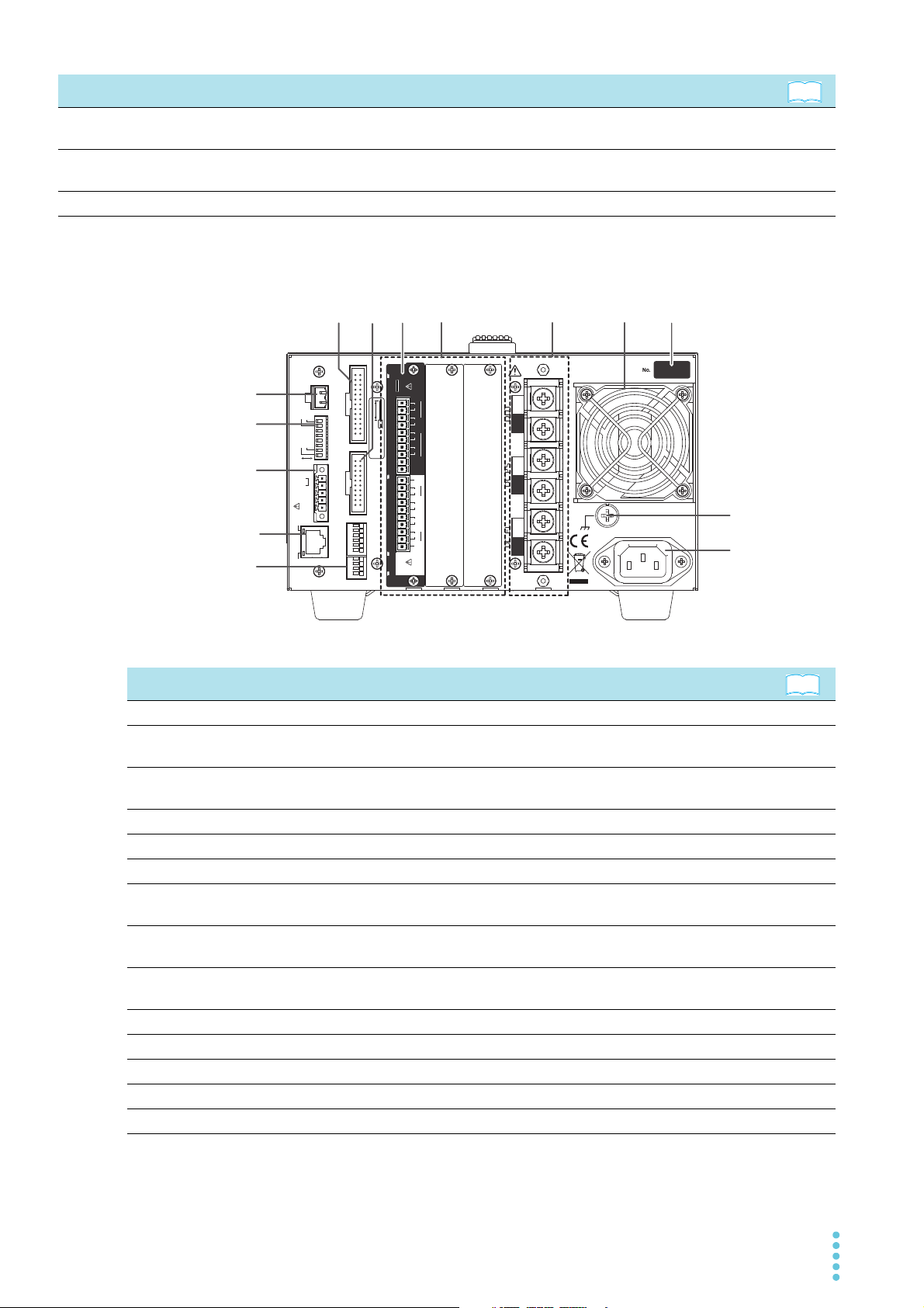
Rear panel
p.52
p.34 p.37
No. Name Function
EXT CONT terminal board External control terminal p.52
1
SENSING connector A connector for the sensing cables
2
S1 switch
3
TP-BUS connectorb A connector for maintenance
4
DC POWER SUPPLY connector A connector for controlling the power supply p.28
5
DC ELECTRONIC LOAD connector A connector for controlling the Electronic load p.31
6
Volt / Thermometer Unit
7
(OP02-PFX)
Extra slots for the option board
8
9 Input/Output terminal board
Air outlet Exhaust port for cooling
10
Serial number
11
Chassis terminal A terminal used for ground the output p.24
12
AC INPUT connector AC inlet p.22
13
PFX2512_CE 9
LAN connector A connector for communicating with BPChecker3000 p.32
14
*1. The terminal cover for protecting the input/output terminal is being attached to the terminal when the PFX2512 is shipped from the
factory.
Setting switches for the termination of TP-BUS, the addresses, and
the vibration sensor.
An option board for expanding the number of voltage and
temperature measurement points
Slots for installing the option board
From the left: slot 1, slot 2, and slot 3
Terminals for the testing device (DUT), the DC power supply
*1
(DCPS), and the Electronic load (DCEL)
--
p.46
p.48
p.42
-
p.20
p.75
p.20
p.75
p.24 p.27
p.29 p.44
-

10 PFX2512_CE
This page is intentionally blank.

General Description
This chapter describes the outline of product,
the connectable equipments, and the
options.

Product Overview
The Charge / Discharge system Controller PFX2512 is a controller exclusively designed for the
charge and discharge control combined with the DC power supply and the Electronic load that
evaluates the characteristic of the DUT such as rechargeable batteries, and measures the value of
charge and discharge voltage/current of the DUT in high accuracy. The configured system may
apply to the high performance evaluation test of the large scale and wide range of ratings by the
combination of the DC power supply and the Electronic load.
For the system requirements, see the BPChecker3000 application software's help file .
Features
Charge / Discharge Control system
● Applies to the wide range of power ratings.
The PFX2512 can be used for the wide range of power ratings combined with the selected
model of Kikusui's DC power supply and the Kikusui's Electronic load. The initial cost can be
reduced by selecting the equipment applied to the desired testing condition of the charge /
discharge test.
● Adopting the digital control of the constant current (CC) and the constant voltage (CV).
The PFX2512 equips the control method of Digital CC / CV, it minimize the difference between
the setting accuracy and the drift characteristic of constant current (CC) / constant voltage (CV)
generated from the system configuration of the DC power supply and the Electronic load, and it
can apply for the precise evaluation. Any of the adjustment are not required after the system
configuration is set up.
● Precise measurement
The PFX2512 equips the high precision measurement circuit and it detects the battery voltage
and the charge and discharge current in high accuracy. (voltage measurement: 100 µV
resolution and current measurement: 100 µA resolution, and the elapsed time measurement:
within 30 seconds per month (within 10 ppm))
Capable of measuring the amount of power and the integrated capacity even with the pulse
current which is hardly captured.
● Protection functions
The PFX2512 equips the route switch (load switch) which it has a feature of high-speed
interruption function to disconnect immediately between the DUT and the DC power /
Electronic load when the abnormal state are detected.
It detects such as an incomplete connection of the DUT, an abnormality of wirings, the potential
difference when it exceeds a regulated value of the DUT cable and the voltage sensing line, and
it protects connecting equipments and the DUT (battery) from being damaged.
● Equipped with the vibration sensor
In case of disaster, the PFX2512 detects a big shake and the impact when the charge/discharge
test is executed, and it turns off the output. it protects connecting equipments and the DUT
(battery) from being damaged.
12 PFX2512_CE

Product Overview
● 1000-step pattern charge/discharge feature
You can set up to 1000 CC or CP (with V or I limits) steps.
High-speed charge/discharge switching control enables you to perform complicated charge/
discharge tests with step times as short as 100 ms. The PFX2512 can be used to create a wide
variety of test and simulation patterns for standard tests.
● High-speed charge/discharge switching
Traditionally, it has taken time to switch between controlling power supplies and controlling
electronic loads. This product can be used to control power supplies and electronic loads at the
same time, which enables seamless charge/discharge switching.
● High-speed sampling as fast as 1 sample/ms
Voltage and current can be measured at an interval as short as 1 ms with the specified voltage
or current step as the trigger. You can acquire highly accurate voltage waveforms that are
synchronized with the step current. This is an optimal feature for analyzing DUT impedance and
evaluating service life.
● Expandable measurement feature
By installing a Volt / Thermometer Unit OP02-PFX, you can expand the number of measurement
points by four voltage and four temperature measurement points. There are three option board
slots, so you can expand the number of measurement points by a maximum of 12 voltage and
12 temperature measurement points.
1
General Description
● Support of EV-related standards through the use of the new, specialized application
software BPChecker3000 (sold separately)
BPChecker3000 supports tests for EV-related standards such as the IEC standards. This software
is easy to use and works well with Microsoft Office software. It also has features for displaying
and exporting high-speed sample data.
PFX2512_CE 13
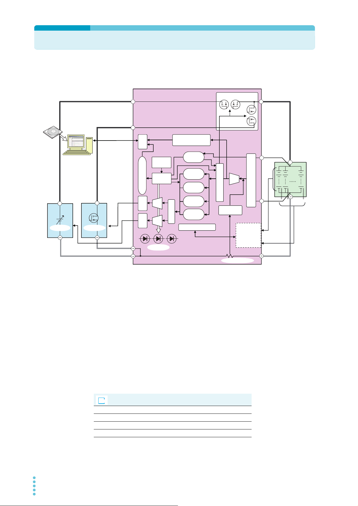
System Configuration
CC
SDRAM
measurement memory
Load Switch
LAN
CC/CV
+
+
+
+
+ +
+S
-S
BPChecker3000
ADC
Protection
control
Communication control
Isolator
Time base
Digital CC
control
Sequence
control
Digital CV
control
Digital CP
control
Pulse
control
Option communication
Current
measurement
Voltage measurement protection
DUT
I/F
PFX2512
I/F
The load switch control
The applied
voltage of
each cell /
temperature
measurement
board (Option)
DAC
DAC
Indicator
Current detection
Votage sensing
Cell voltage
Cell
temperature
Votage
sensing
DC power
supply
Electronic
load
Analog I/F Analog I/F
Charge / Discharge System configulation (Example)
?
Help
The figure below shows an example of basic configuration of the charge and discharge system
using the PFX2512. The system consists of the selected Kikusui's Electronic load and the DC power
supply combined with a peripheral subsystem.
The functional block of the PFX2512 are composed of measurement function of the DUT voltage /
current / temperature, control function of the digital constant current / constant voltage, I/F
function of the power supply / Electronic load, host communication control function, and the load
switch function.
The PFX2512 is equipped with the I/F that can be connected directly with the selected Kikusui's
Power supply and the Electronic load. It only requires simple initial setting and no other
equipments or external circuit are required, the PFX2512 is designed to perform the complete
charge and discharge test.
The connection status with the Power supply, the Electronic load, and the DUT (battery) is always
monitored, and when any status of abnormality is detected, the PFX2512 has a function to stop
safely the charge and discharge testing condition.
The PFX2512 is controlled from a PC through the LAN interface.
Use the application software
operate the PFX2512.
Hardware configuration Io Config
Test condition creation Test Condition Editor
Test execution Test Executive
Test result analysis Graph Viewer
BPChecker3000
BPChecker3000
to set the charge/discharge test conditions and to
14 PFX2512_CE
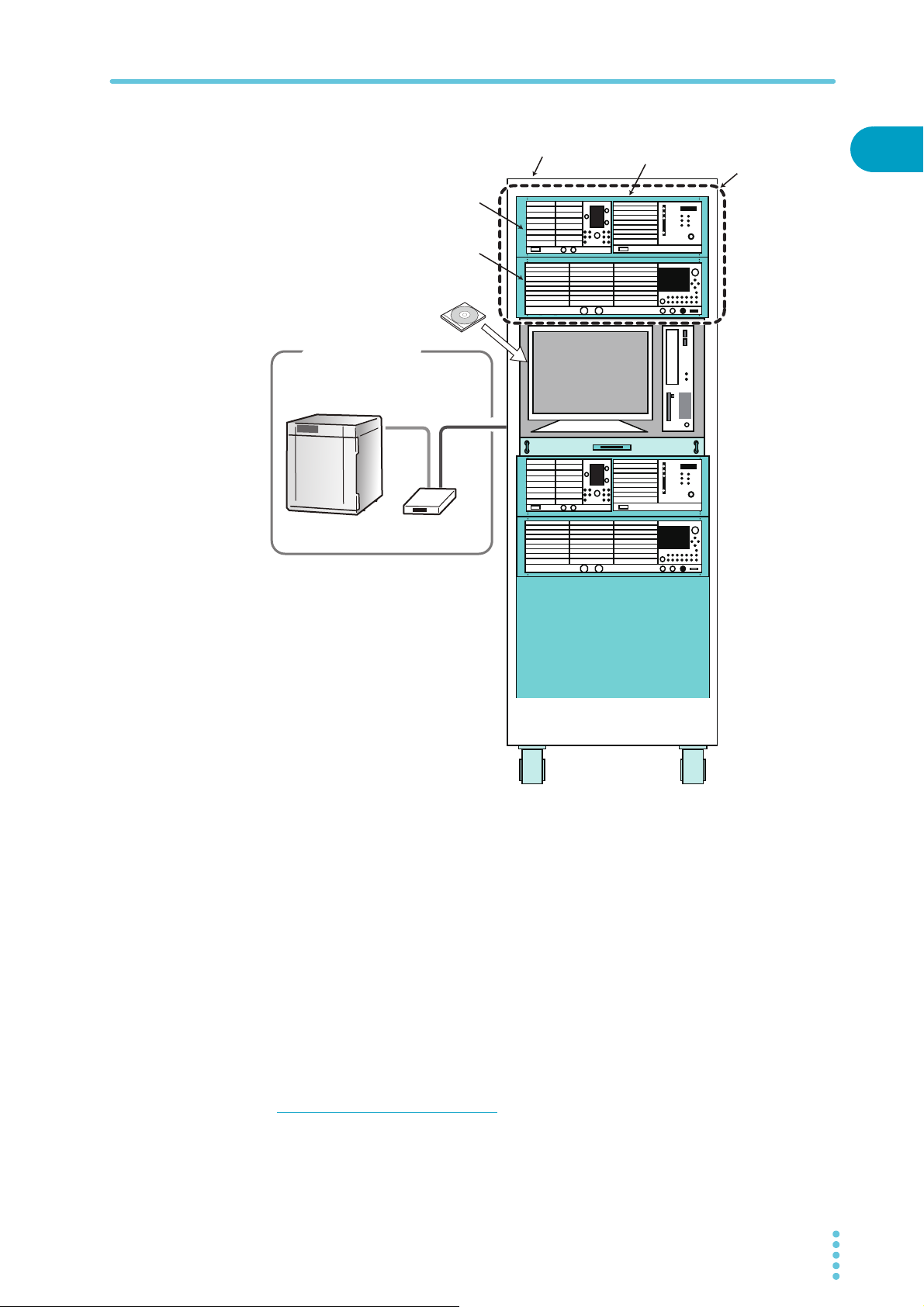
System Configuration
USB-RS485 converter
Temperature chamber by ESPEC Corp.
that can be controlled using the RS485.
USB
Application software
BPChecker3000
EIA standard rack
Charge / Discharge
Unit
DC Power Supply
PWR800L
Charge / Discharge System Controller
PFX2512
Electronic Load
PLZ1004W
Synchronized T est
RS485
2 channels Charge / Discharge System configulation
(Example)
1
General Description
The 1 channel of the charge and discharge system consists of one unit of each PFX2512, DC power
supply, and Electronic load.
The figure shown above is an example of system configuration for 2 channels of the charge and
discharge system. This system consists of 2 sets of each for the PFX2512, PWR800L (DC power
supply), the PLZ1004W (Electronic load) , and 1 set of each for the PC installed into the rack unit
connecting with the temperature chamber.
If your system configuration includes a PFX2512, you can connect up to seven channels of charge
and discharge units.
The synchronized testing with the temperature chamber can be performed. The PC can be
connected with the temperature chamber (manufactured by ESPEC) through USB to RS485 using
the exclusive design of converter.
synchronized tests, you require a VISA library.
*1
If you want to use a temperature chamber to perform
*2
*1. Use a converter of the ESPEC corp. recommended.
*2. VISA (Virtual Instrument Software Architecture) is a standard developed by the VXIplug&play Systems
Alliance that defines software specifications for communicating with instruments from a PC. KI-VISA is a
Kikusui-original VISA library that complies with the VXIplug&play VISA specifications. You can download
the latest version of KI-VISA from the Kikusui website (http://www.kikusui.co.jp/en/download/).
PFX2512_CE 15

Applied DC Power Supplies and Electronic Loads
See
The maximum voltage and the maximum current for charge and discharge testing shall be
determined by the connected DC power supply and the Electronic load unit.
The PFX2512 can be used to perform the charge and discharge testing with the following system
configuration. Select the system which applies to your required charge and discharge testing.
p. 56
Each of the system configuration is assigned for the specific model ID. Set the model ID number
according to your operating system configuration.
The system of which model ID has not been assigned shall be subject to concern when the future
upgrade version is made.
As for the latest information for the system configuration can be confirmed on our website (http://
www.kikusui.co.jp/en). Please contact our distributor or agent for details.
The factory default settings are arranged by the following configuration.
DC Power supply: PWR800L
Electronic load: PLZ1004W (H range)
■ Applied configuration
Model ID DC Power
*2
7101
7102 PWR800L PLZ1004W (M range) 800 W 1 000 W
7103 PWR1600L PLZ1004W (2 units parallel) 1600 W 2 000 W
7104 PWR800L PLZ334W (H range) 800 W 330 W
7106 PWR1600L PLZ1004W (H range) 1600 W 1000 W
7107 PAS10-70 PLZ1004W (H range) 700 W 1000 W
7108 PAS20-36 PLZ1004W (H range) 720 W 1000 W
7109 PAS20-54 PLZ1004W (H range) 1080 W 1000 W
7110 PAS40-27 PLZ1004W (H range) 1080 W 1000 W
7111 PWR800L PLZ164W (H range) 800 W 165 W
7112 PAS10-35 PLZ334W (H range) 350 W 330 W
*1. Because of the route loss, the maximum power may not be reached to the specified number as
*2. Default setting at the time of shipment.
supply
PWR800L PLZ1004W (H range) 800 W 1000 W
indicated.
Electronic load Maximum charging
power
*1
Maximum
discharging power
16 PFX2512_CE
Applied DC Power Supplies and Electronic Loads
Charge operation range of the DC power supply
0.0
10.0
20.0
30.0
0
2.557.5
10
12.51517.52022.52527.53032.53537.54042.54547.5
50
40.0
50.0
PWR800L
PWR1600L
60.0
70.0
Voltage (V)
Current (A)
PAS40-
**
PAS20-
**
PAS10-
**
PFX2512 Operating range
DUT cable : Nominal cross-sectional area at 14 mm
2
5 m
Voltage (V) axis
Constant voltage value (CV Voltage), or End voltage value (MAX Voltage)
Current (A) axis Constant current value (CC Current)
Selecting the system for the DC power supplies and the electronic loads
The range is different between the charge operation and the discharge operation state. Select the
applicable model of the DC power supply and the Electronic load that meets each requirement.
The following graph indicates the range of allowable charge voltage value / current value
calculated by the formula specified below. Use the equipments which do not exceed the range of
the voltage value (constant voltage value/end voltage value) and the current value (constant
current value).
1
Maximum charging power = Maximum rated power of the DC power supply - Route loss
*1
When the charging power exceeds the range of allowable power of the power supply while the
charge operation is executed, the PS / B alarm will be activated and stop the testing.
General Description
PFX2512_CE 17
*1. What is the route loss?
The voltage drop is occurred in the DUT cable, the connecting cable, and the PFX2512 current
passing circuit, etc. caused by flowing the charging current. The route loss is the power loss of the
voltage drop while the execution of charging state. The allowable maximum power in the charging
state is the value subtracting the route loss.
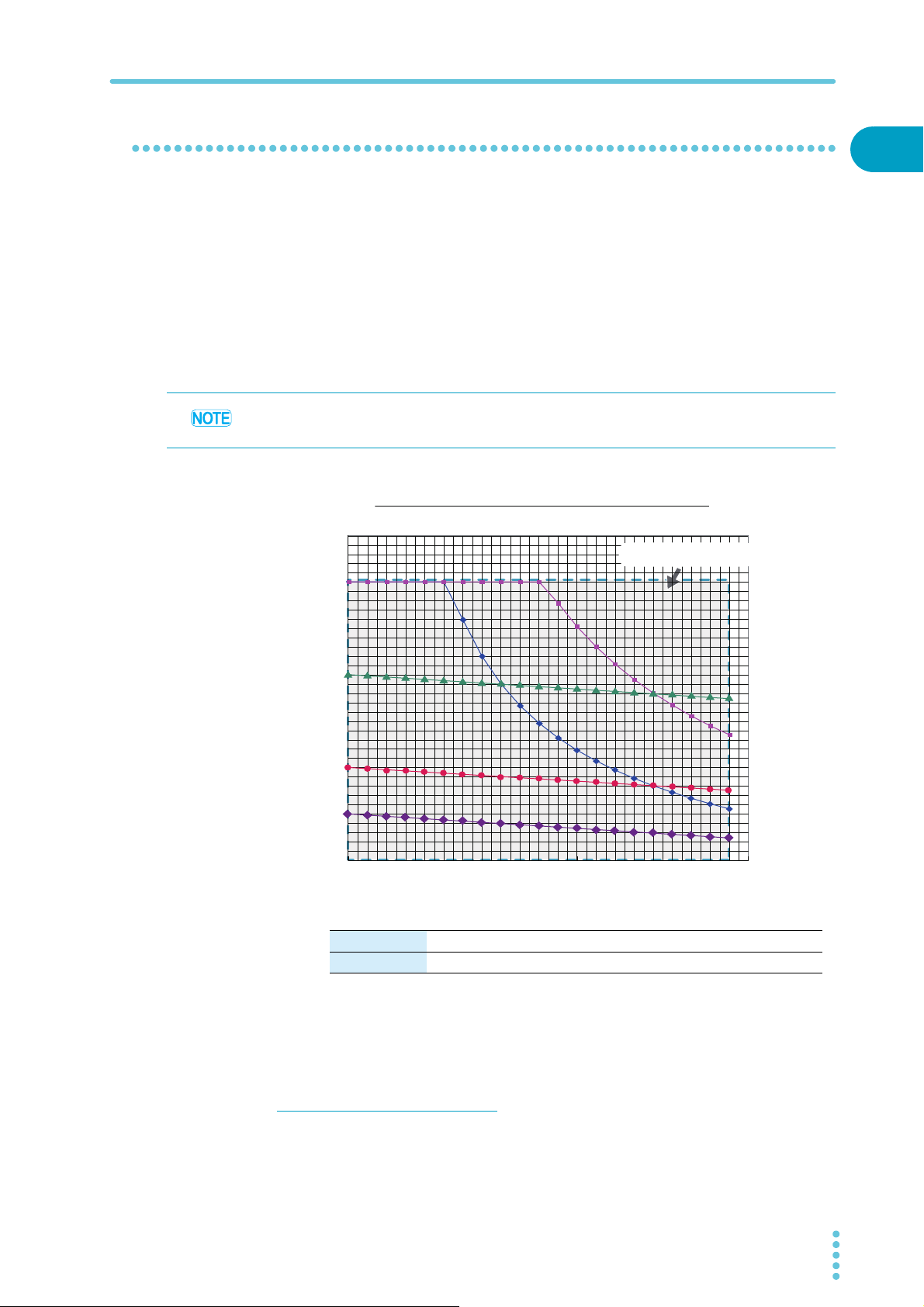
Applied DC Power Supplies and Electronic Loads
See
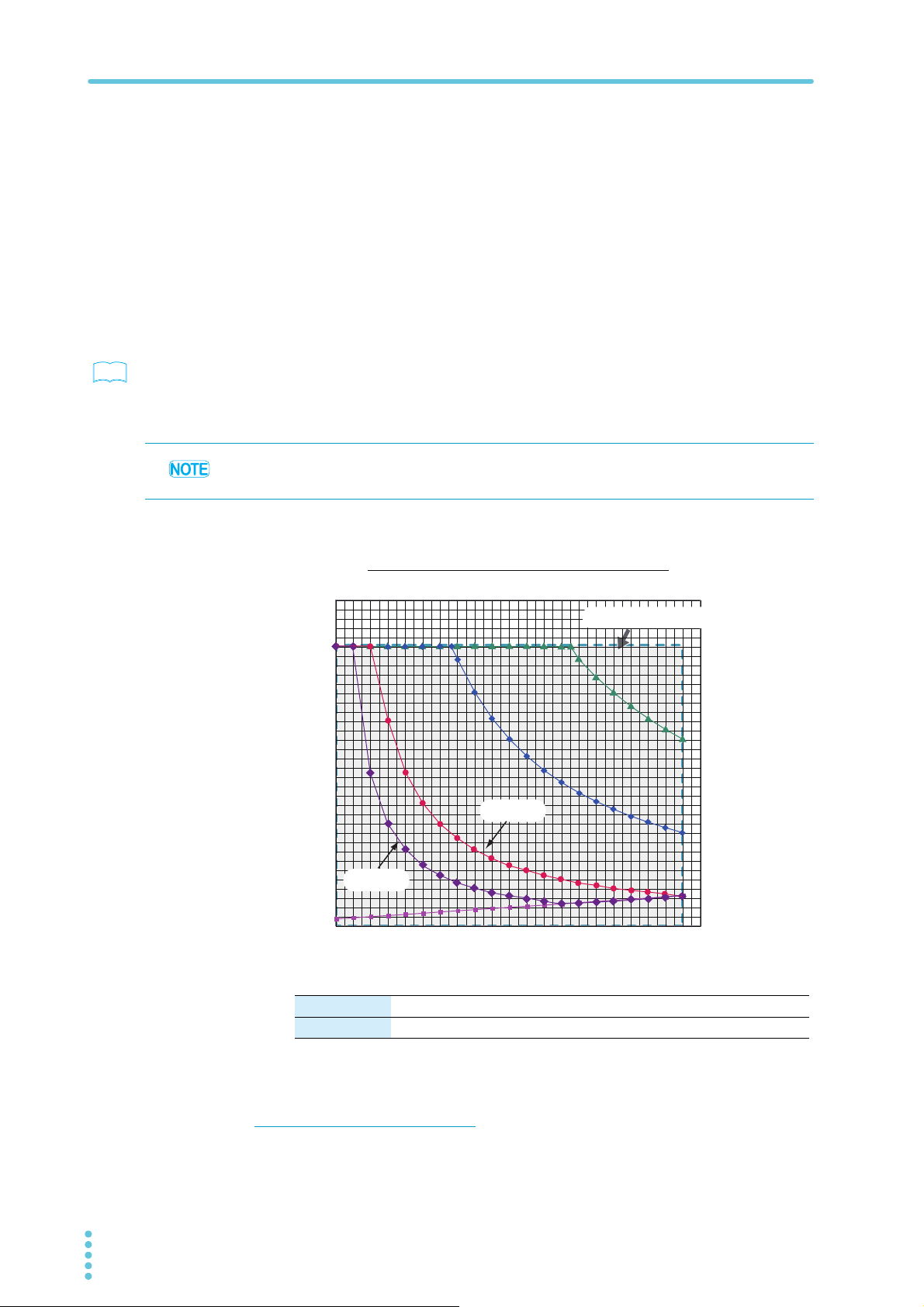
Voltage (V) axis
Start discharge voltage value (Start Voltage), or End voltage value (Cutoff Voltage)
Current (A) axis Constant current value (CC Current)
The following graph indicates the range of allowable charge voltage value / current value
calculated by the formula as specified below. Use the equipment that should not exceed the range
of the voltage value (starting discharge voltage value/end voltage value) and the current value
(constant current value). And the discharge voltage should not be applied below the discharge
minimum operating voltage.
When using the constant power discharge function (CP Dish), calculate the value of the discharging
current from the setting value of the constant power and the DUT (battery) voltage, and confirm its
value is within the range of the graph.
Discharge minimum operating voltage*1=
Minimum operating voltage of the Electronic load + the value of voltage drop caused by the route loss
p. 93
You can perform discharge tests with voltages that are lower than the discharge minimum
operating voltage by using a bias power supply.
When the Electronic load exceeds the allowable power or becomes under the lowest discharge
operating voltage while the discharge operation, the CD / B alarm is occured and abort the test.
Discharge operation range of the Electronic load
70
60
50
40
30
Voltage (V)
20
DUT cable : Nominal cross-sectional area at 14 mm
PFX2512 Operating range
PLZ334W
2
5 m
PLZ1004W
2 units parallel
operation
PLZ1004W
10
PLZ164W
PLZ-4W
Minimum operating
0
0
2.557.5
10
12.51517.52022.52527.53032.53537.54042.54547.5
voltage
50
Current (A)
*1. What is the discharge minimum operating voltage?
The discharge minimum operating voltage relies on the minimum operating voltage of the
Electronic load. Furthermore, the discharge minimum operating voltage shall be determined with
adding the value of route loss (the voltage drop).
18 PFX2512_CE
Options
Brackets
Handle
Covers
M4 flat head screws
(M4x0.7x8)
Rubber feet (4 locations)
Collars (4 locations)
Attachment screws
(4 locations)
M4 screw
Maximum depth: 16 mm (0.63 inch)
( )
For details on the options, contact your Kikusui agent or distributor.
Rack mounting options
Product Model Notes
Rack mout frame KRA3 Inch rack EIA Standard
KRA150 Milli rack JIS standard
149
132.5 (5.22)
57 (2.24)
100
1
General Description
Unit : mmUnit : mm (inch)
37.75
(1.49)
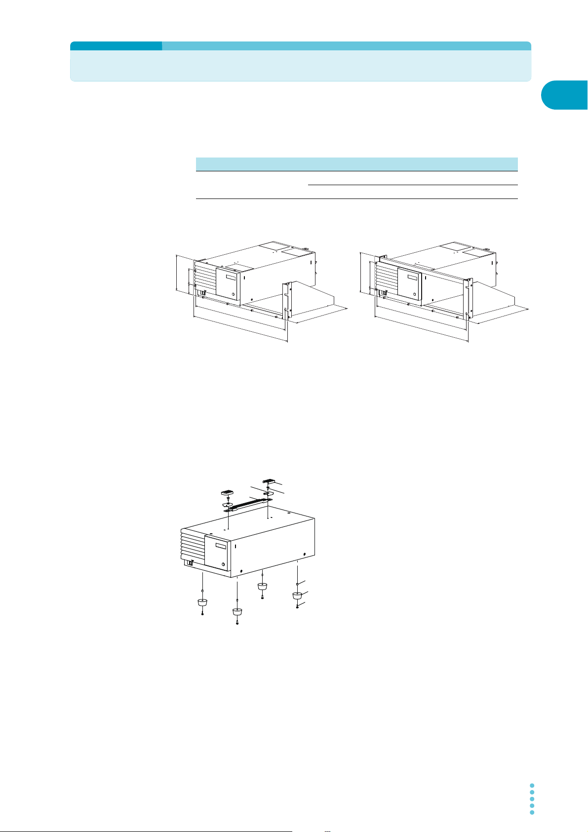
Remove the handle and rubber feet before you mount the product to a rack.
For details on rack mounting, see the KRA series or KRB series Operation Manual. Install the suitable
support angles applying to the used rack system to support the instrument.
We recommend that you keep all the parts so that you can use them again when you detach the
PFX2512 from the frame.
To reattach the rubber feet, use the screws that you removed.
(460 (18.11) )
482 (18.98)
260 (10.24)
KRA3
24.5
( 460 )
480
260
KRA150
Removing the handle and rubber feet
Pull up on the handle covers (two locations).
1
PFX2512_CE 19
Unfasten the M4 flat head screws (two locations) and remove the entire
2
handle.
Unfasten the screws and remove the four rubber feet.
3
Options
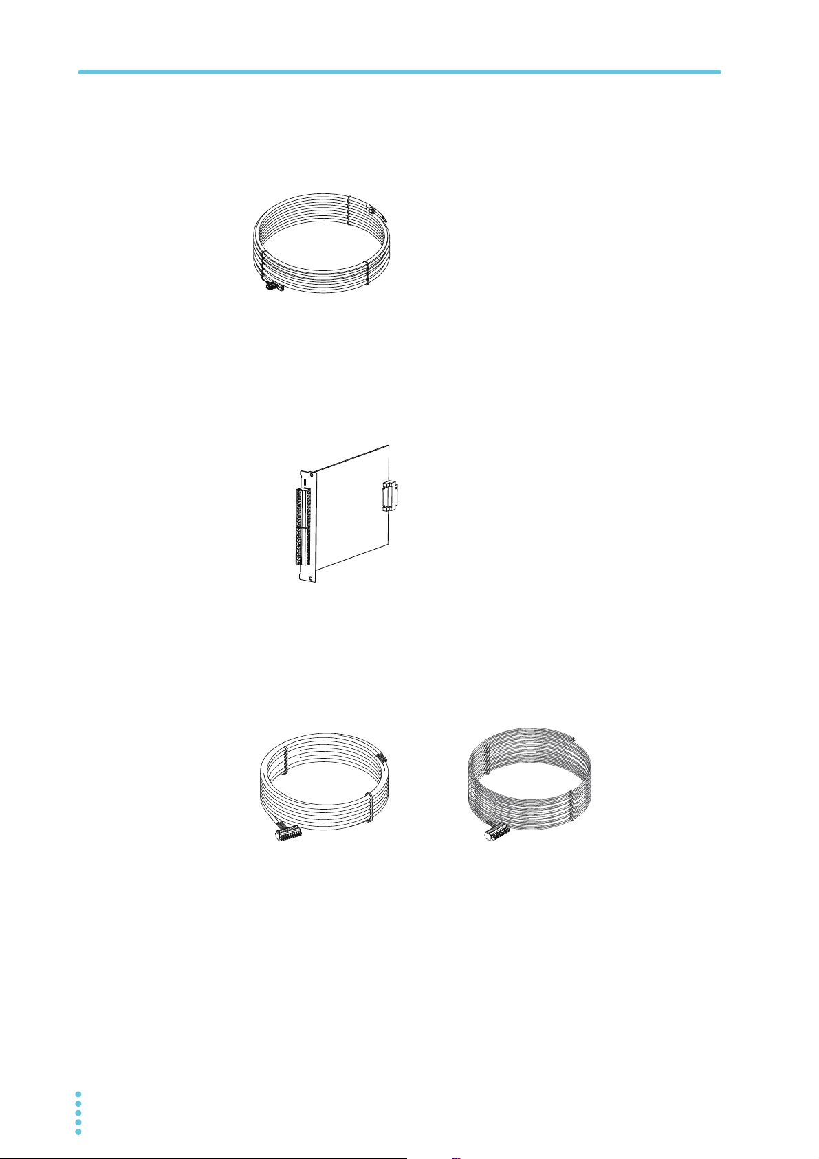
Load cable TL08-PFX
The dedicated load cable for connecting the PFX2512 and the DUT (battery). It makes easier for the
connection, because the cable and the sensing cable are assembled.
Volt / Thermometer Unit OP02-PFX
This is an expansion board for the measurement feature. By installing this board, you can expand
the number of measurement points by four voltage and four temperature measurement points.
There are three option board slots, so you can expand the number of measurement points by a
maximum of 12 voltage and 12 temperature measurement points.
Sensing cable set TL09-PFX
This cable set consists of a dedicated voltage sensing cable and thermocouple for connecting the
DUT (battery) to a PFX2512 in which a Volt / Thermometer Unit OP02-PFX is installed. This product
supports four voltage and four temperature measurement points. Connectors are attached to these
cables, so it is easy to connect them to the DUT and the PFX2512.
Voltage sensing cable
Thermocouple
20 PFX2512_CE

Installation and Preparation
This chapter describes the procedures of
unpacking and preparation of the PFX2512
before use .
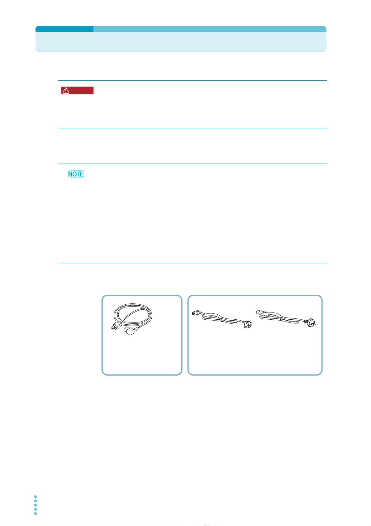
Connecting the Power Cord
WARNING
Rating : 125 Vac/ 10 A
PLUG : NEMA5-15
[85-AA-0003]
Rating : 250 Vac/ 10 A
PLUG : CEE7/7
[85-AA-0005]
Rating : 250 Vac/ 10 A
PLUG : GB1002
[85-10-0790]
Power cord for 100 V System
Power cord for 200 V System
Possible electric shock.
• The PFX2512 is an IEC Safety Class I equipment (equipment with a protective conductor
terminal). Be sure to ground the product to prevent electric shock.
• The PFX2512 is grounded by the earth wire of the AC power cable. Connect the ground
terminal to earth ground.
Connecting the power cord with a plug
• Use the supplied power cord to connect to an AC power line.
If the supplied power cord cannot be used because the rated voltage or the plug shape is
incompatible, have a qualified engineer replace it with an appropriate power cord that is 3 m or
less in length. If obtaining an appropriate power cord is difficult, consult your Kikusui agent or
distributor.
• A power cord with a plug can be used to disconnect the PFX2512 from the AC line in an
emergency. Connect the plug to an easily accessible power outlet so that the plug can be
removed from the outlet at any time. Be sure to provide adequate clearance around the power
outlet.
• Do not use the supplied power cord for other devices.
• It may cause a damage of the test data or a malfunction of the product, please connect the
power cable of each equipment to the same outlet.
The PFX2512 is designed as an equipment of IEC Overvoltage Category II (energy-consuming
equipment supplied from the fixed installation).
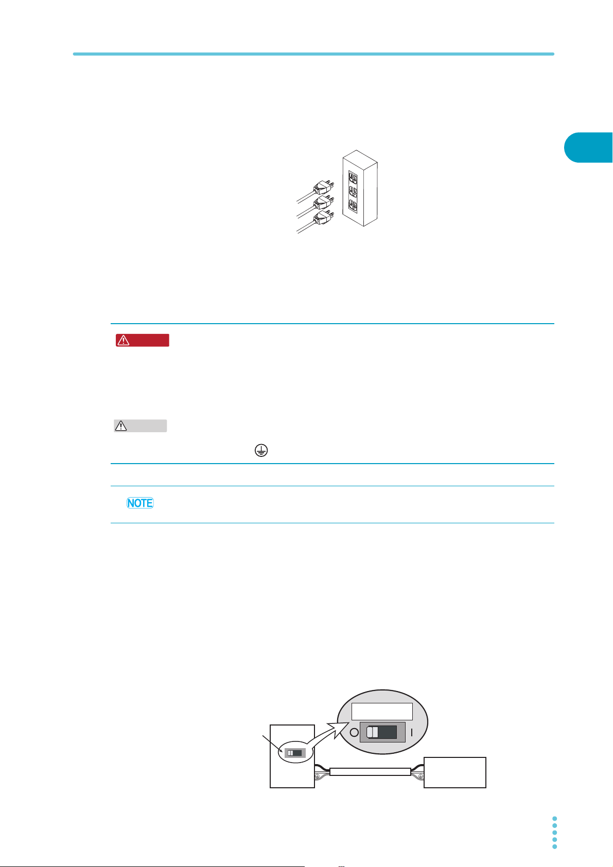
Confirm that the POWER switch of all connected equipments are turned off.
1
Check whether or not the AC power line is compatible with the input rating of
2
the PFX2512.
The product can receive a nominal line voltage in the range of 100 Vac to 240 Vac at
50 Hz or 60 Hz.
The power cord of the all connected equipments should be connected with
3
the AC INPUT inlet of a rear panel of each equipment.
22 PFX2512_CE
Connecting the Power Cord
PFX2512
DC Power Supply
Example properly ground power outlet for use
Electronic Load
Connect the power cord
of each equipment to a
properly ground power
outlet.
WARNING
CAUTION
N
L
N
L
Connection to the switchboard
(PWR1600L example)
PWR1600L
30 A
Breaker indication example
PWR1600L
Breaker dedicated
to the PWR1600L
Switchboard
To ensure the safety charge and discharge testing, the power cord of the all
4
connected equipments should be connected to the outlet with the same
ground terminal.
Protect the malfunction in such case when the AC power line is shut down.
Connection to the switch board
To ensure the safety charge and discharge testing, the AC power line connected with other
equipments should be wired to the same AC power line.
Possible electric shock.
• Turn off the circuit breaker of switchboard before connecting the cord.
Possible Fire.
• Have a qualified engineer connect the power cord to the switchboard.
• The breaker of switchboard is required to meet following requirement.
2
Installation and Preparation
Inside the product, protective circuits including input fuses are connected to match the polarity of
the input terminal. Make sure the colors of the wires connected to the corresponding input
terminals (L, N, and (GND)) are correct.
Turn off the circuit breaker of switchboard to disconnect the PWR from the AC line in an
emergency.
■ Circuit breaker of switchboard requirement
• Rated current: 30 A (The circuit breaker of which the rated current is more than 30 A is
disabled for safety.)
• The breaker of the switch board should be assigned exclusively for the equipment used in the
system.
• Keep the switchboard easily accessible at any time.
• It is required to indicate that the breaker is used exclusively for the equipment of the system
and it separates the AC power supply line.
PFX2512_CE 23
Connection and Setting of the Each Equipment
WARNING
–
+
PLZ1004W
PWR800L
PFX2512
– DC OUTPUT +
– DC INPUT +
J1
J1
To PWR +
To PWR
–
To DUT +
To DUT
–
To PLZ +
To PLZ
–
To PWR J1
To PLZ J1
26-conductor flat cable
(Accessory)
Cable with crimp
terminal (Accessory)
Chassis terminal
Thermistor
(Accessory)
20-conductor flat cable
(Accessory)
–
+
DUT cable
DUT cable
Voltage
sensing cable
Temperature
sensing cable
DUT (battery)
+
–
The dedicated load cable (TL08-PFX) is available
as an optional item.
*
*
*
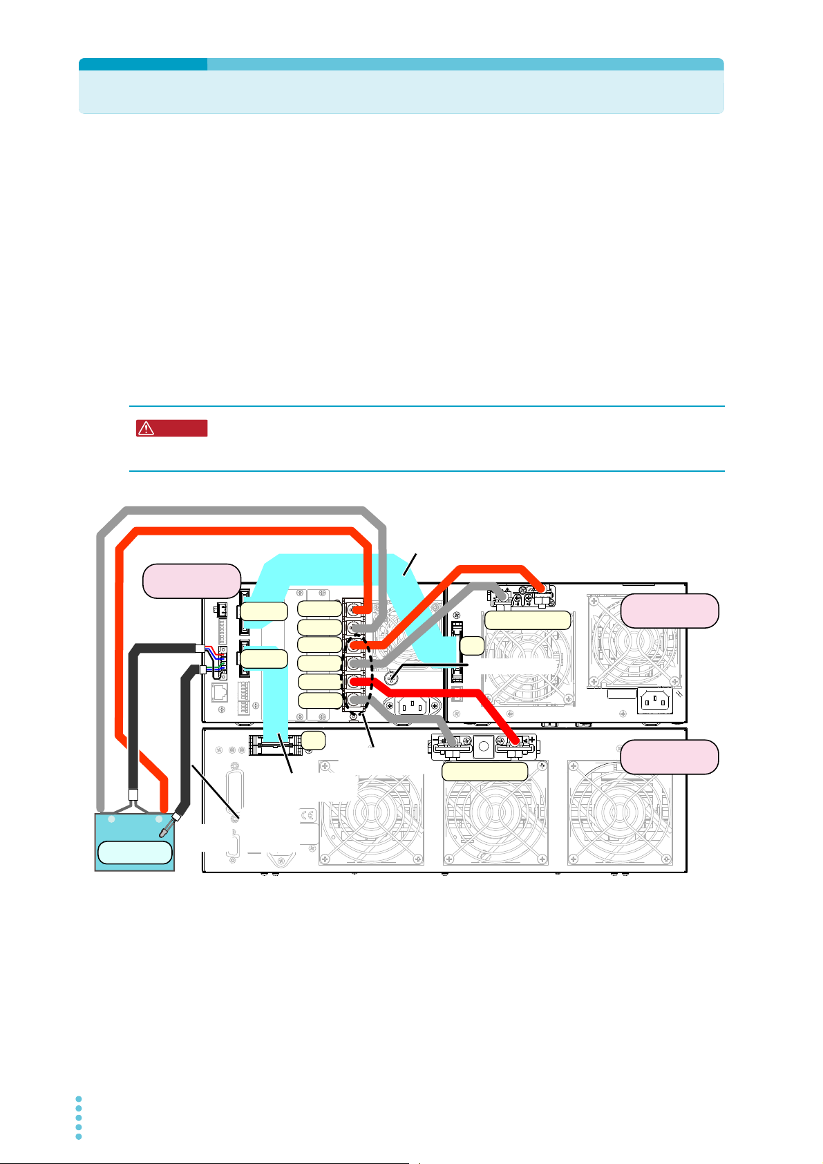
Example of connecting figure of the charge / discharge system with the DUT (battery)
The following example is consisting of the Charge/ Discharge System Controller (PFX2512), DC
power supply (PWR800L), the Electronic load (PLZ1004W), and the DUT (battery).
The direction of leading cables of input / output terminal board can be either right or left angle.
However, wire the all the cables to become same directions as possible. Use the cable whichever it
comes as standard accessory.
Please note the following for the stability of operation, the reduction of noise effect, and the
prevention of the malfunction.
• Twist the cables between the equipments.
• Do not entwine or cross of the connected cables between the equipments.
• Do not entwine the cable with the flat cable which flows, and do not pass through the
clearance between the +DUT cable and the -DUT cable.
The following describes connecting procedure for the entire system. Please refer to the connection
between each equipment.
Possible electric shock. It is not concerned of any sequence of the connecting equipments,
however, the DUT (battery) must be connected at the final connection and it must be
connected from the side of PFX2512.
■ Connection for the chassis terminal
The chassis terminal is used for an earthing terminal as multipurpose usage. It can be applied to the
reduction of noise under the large current operation, and prevention of the malfunction. Even if the
cable come in contact with the chassis by any chance, it can prevent the electric shock accident. To
secure the safety operation of the charge and discharge testing, it is recommended to earthing the
chassis terminal.
For the ground cable of the chassis terminal, use the cable with higher capacity of the maximum
current necessary for the charge and discharge testing.
24 PFX2512_CE
Connection and Setting of the Each Equipment
–
+
TP-BUS
NC02087-2
J1
100-240V 50-60Hz
2600VA MAX
AC INPUT
PLZ1004W
Master
Slave
PLZ1004W
PWR1600L
PFX2512
– DC OUTPUT +
– DC INPUT +
– DC INPUT +
J1
J2
J1
J1
–
+
–
+
DUT cable
DUT cable
26-conductor flat cable
(Accessory)
Voltage
sensing
cable
Temperature
sensing cable
DUT (battery)
Cable with crimp
terminal (Accessory)
20-conductor flat cable
(Accessory)
Chassis terminal
Thermistor
(Accessory)
To PWR J1
To PLZ J1
To PWR +
To PWR
–
To DUT +
To DUT
–
To PLZ +
To PLZ
–
The dedicated load cable (TL08-PFX) is available
as an optional item.
*
*
*
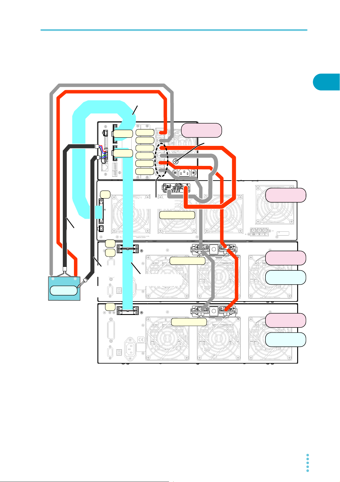
Example of charge / discharge system by connecting two units of the PLZ1004W in master-slave
The following shows an example of system configuration which consist of 1set of the Charge/
Discharge System Controller (PFX2512), 1 set the DC power supply (PWR1600L), and 2sets of the
Electronic load (PLZ1004W) in parallel operation. As for the parallel operation of the Electronic load
units (PLZ1004W), locate the master unit with a position nearest to the PFX2512.
2
Installation and Preparation
Connecting the each equipment
1
2
Confirm that the POWER switch of all connected equipments are turned off.
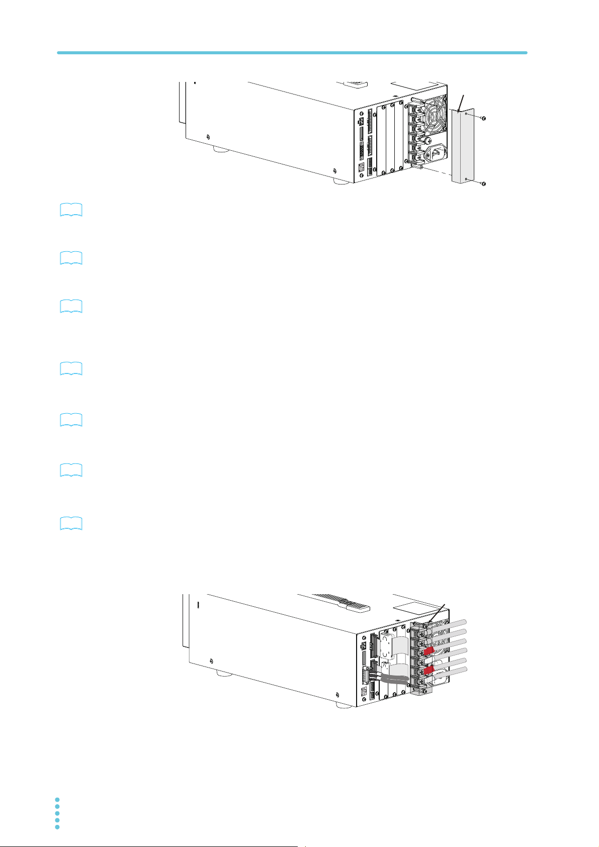
Remove the terminal cover attached to the input/output terminal board on
the rear panel of the PFX2512.
PFX2512_CE 25
Connection and Setting of the Each Equipment
Terminal cover
Remove the terminal cover
See
See
See
See
See
See
See
Terminal cover
Example of complete connecting
figure of the rear panel
p. 27
p. 29
p. 32
p. 38
p. 39
p. 42
Connect the PFX2512 to the DC power supply.
3
Use the cable with a crimp terminal which comes with the PFX2512 as a standard
accessory.
Connect the PFX2512 to the Electronic load.
4
Use the cable with a crimp terminal which comes with the PFX2512 as a standard
accessory.
If you want to use BPChecker3000, connect the PFX2512 and the PC.
5
Use the LAN cable to connect the LAN interface.
Set the each equipments
Set the DC power supply
1
Set the protection function, then switch to the operation state in the external analog
control.
Set the Electronic load.
2
Set the protection function, then switch to the operation state in the external analog
control.
Set the state of S1 switch.
3
Connecting the DUT (Battery)
p. 44
Connect the DUT (Battery) with the PFX2512.
1
Use the DUT cable, the voltage sensing cable, and the temperature sensing cable.
When all of the connection between equipment are completed, attach the
2
terminal cover on the input/output terminal board.
Attach the terminal cover along with the direction of wiring cables.
26 PFX2512_CE

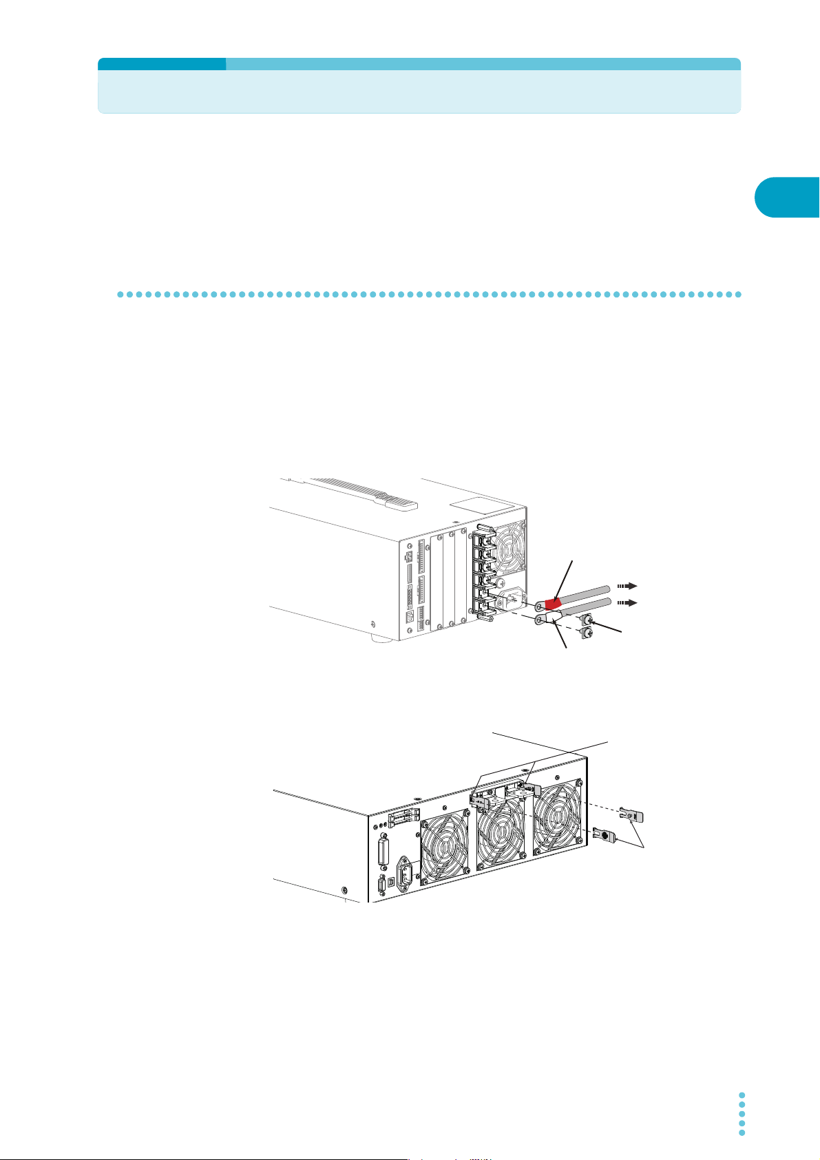
Connecting with the DC Power Supply
Screw (M6)
To DC power supply
– terminal
To DC power supply
+ terminal
Cable with crimp terminal (+: Red)
Cable with crimp terminal (–: White)
Memo
Connection using M8 screws
(Example of PWR800L)
Screw (M8)
Spring washer
Nut
Crimp
terminal
Cable with crimp terminal (+: Red)
Cable with crimp terminal (–: White)
Chassis terminal
Do not connect the chassis
wire to the chassis terminal.
Ope
Connect the PFX2512 to the DC power supply using the cable with the crimp terminal and the 26conductor flat cable.
The following procedure refers to the case of connecting Kikusui's Regulated DC power supply
PWR800L.
Connecting the cable with the crimp terminal
Confirm that the POWER switch of all connected equipments are turned off.
1
Connect the cable with the crimp terminal to the DC PS + and the DC PS- on
2
the input/output terminal of the PFX2512. The crimp terminal (M6) with a red
cap is connected to the DC PS + terminal, and the crimp terminal (M6) with a
white cap is connected to the DC PS - terminal.
Pull out the cable in horizontal angle and fix it by screws.
2
Installation and Preparation
To prevent short circuits,
this has been designed to
operate in a completely
floating condition.
PWR series
PAS series
PFX2512_CE 27
Remove the chassis wire when it is connected the output terminal of the DC
3
power supply.
The output of the DC power supply is used as floating.
Connect the other end of the cable with the crimp terminal to the output
4
terminal on the rear panel of the DC power supply. The crimp terminal (M8)
with a red cap is connected to the DC OUTPUT + terminal, and the crimp
terminal (M8) with a white cap is connected to the DC OUTPUT -terminal.
Follow the figure for the direction of the screw. If the screw are not mounted correctly,
the OUTPUT terminal cover may not be attached properly.
Insert the hook of the bottom cover into the hole located above and to the left
5
of the output terminal of DC power supply.
The bottom cover is the one without screws.
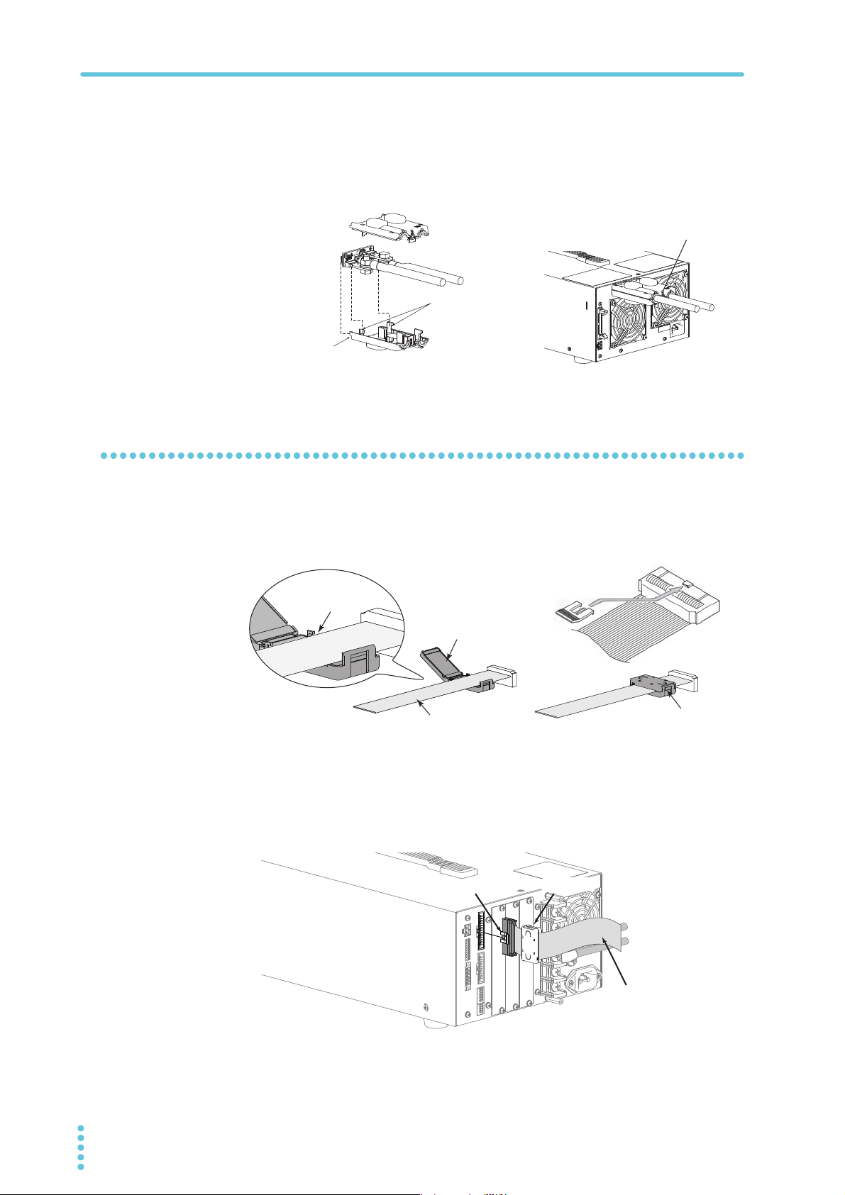
Connecting with the DC Power Supply
Top cover
Align the protrusion
on the inside to the
concavity of the
output terminal
Insert into the hole
in the rear panel
Bottom cover
Attachment of the
OUTPUT terminal cover
(Example of PWR800L)
Flatcable
Ferritecore
Putaflatcable
inunderhook.
26-conductor flat cable
Lock lever
Ferrite core
Align the hook of the bottom cover to the groove located to the side of the
6
output terminal.
Fix them in place using the screws.
7
Check that the screws are securely fastened.
Connecting the flat cable
Align the top and bottom parts
of the terminal cover and screw
them in place.
Attach the lock lever and ferrite core to the 26-conductor flat cable. (those
1
items come with the PFX2512 as standard accessories)
If the lock lever is not attached, the connector may come off.
Securrelylocktheferritecore.
Confirm that the POWER switch of all connected equipments are turned off.
2
Insert the 26-conductor flat cable to the "DC POWER SUPPLY" connector on
3
the rear panel of PFX2512.
Confirm that the lock lever is pulled down and it is firmly connected.
28 PFX2512_CE
Insert the other end of the 26-conductor flat cable to the "J1" connector on
4
the DC POWER SUPPLY.
Confirm that the lock lever is pulled down and it is firmly connected.
Connecting with the Electronic Load
Cable with crimp terminal (+: Red)
Cable with crimp terminal (–: White)
Screw (M6)
To Electronic load
– terminal
To Electronic load
+ terminal
Lock plate
Insert the lock plate to the
groove on the side of the
terminal.
Insert the lock plate
(Example of PLZ1004W)
Connect the PFX2512 to the Electronic load using the cable with the crimp terminal and the 20conductor flat cable.
The following procedure refers to the case of connecting Kikusui's Electronic load PLZ1004W.
Connecting the cable with the crimp terminal
Confirm that the POWER switch of all connected equipments are turned off.
1
Connect the cable with the crimp terminal to the DC EL + and the DC EL - on
2
the input/output terminal of the PFX2512. The crimp terminal (M6) with a red
cap is connected to the DC EL + terminal, and the crimp terminal (M6) with a
white cap is connected to the DC EL - terminal.
Pull out the cable in horizontal angle and fix it by screws.
2
Installation and Preparation
PFX2512_CE 29
Insert the lock plate as included as an accessory to the both side of the load
3
input terminal on the rear panel of PLZ-4W series.
Insert the other end of cable with crimp to the load input terminal cover which
4
comes with a standard accessory of the PLZ-4W series.
Cut the sleeve of the load input terminal cover for the appropriate size that the cable
with the crimp can go through its terminal cover.
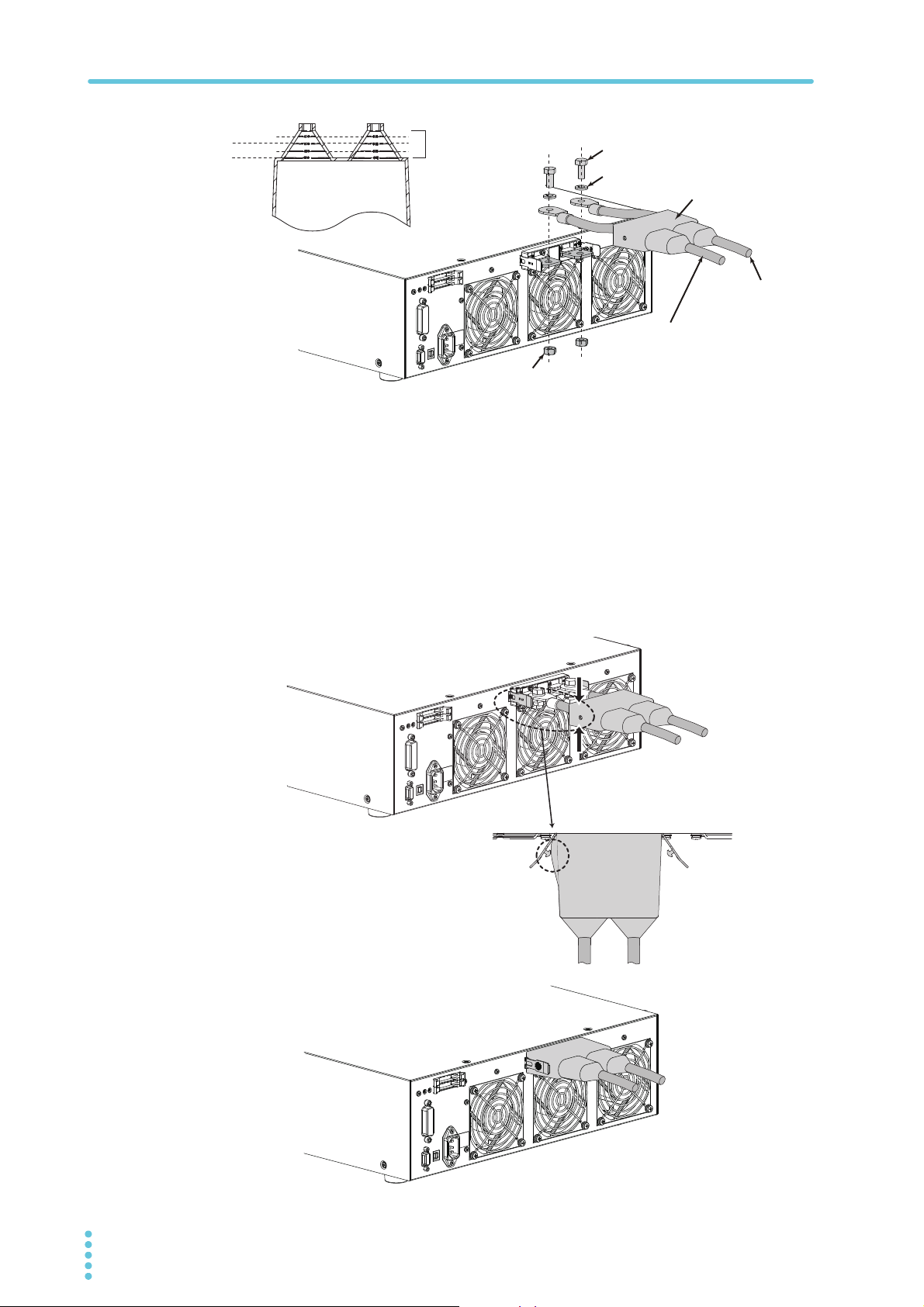
Connecting with the Electronic Load
Bolt (M8 x 18)
Spring washer (M8)
Load input terminal cover
Nut (M8)
Cable with crimp
terminal (+: Red)
Cable with crimp terminal
(–: White)
Using the load input terminal cover (Example of PLZ1004W )
Top view
Move the cover until the edge touches
the panel, and pinch the section indicated
by the arrow to raise the side surface.
With the side surface of the cover raised,
insert the lock plate pin into the hole.
Check that the left and right lock
plate pins are securely inserted in
the cover holes.
Attachment of the load input terminal cover
(Example of PLZ1004W)
φ15 line
φ25 line
φ10 line
φ20 line
5
6
Cut the sleeve to
match the wire
diameter by using
the gauge as a
reference.
Connect the other end of the cable with the crimp terminal to the output
terminal on the rear panel of the PLZ-4W series. The crimp terminal (M8) with
a red cap is connected to the DC INPUT + terminal, and the crimp terminal
(M8) with a white cap is connected to the DC INPUT -terminal.
Use the bolt and the nut which comes with a standard accessory of the PLZ-4W
series. Connect the cable against the input terminal in horizontal angle as possible.
Attach the load input terminal cover to the rear pane of the PLZ-4W series
using the lock plate. Fix the pin located inside of the lock plate through the
hole on the cover side.
30 PFX2512_CE
 Loading...