

Kikusui PCZ1000A Operation Manual

OPERATION MANUAL
AC Electronic Load
Part No. Z1-004-002, IB013706
Jul 2018
PCZ1000A
General
Description
Unpacking
and Installation
Operation
Remote Control
Maintenance
and Calibration
Specifications
Appendix
1
2
3
4
5
6
Use of Operation Manual
19
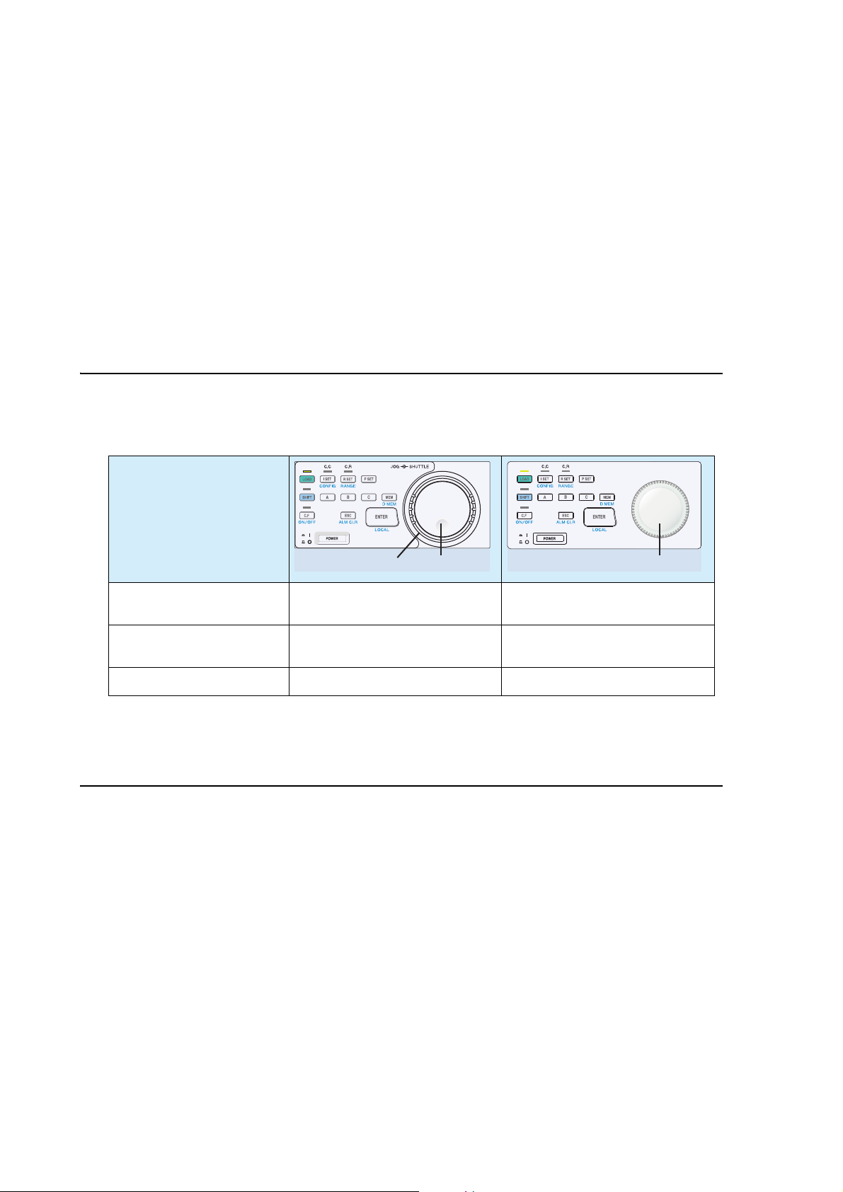
Rotary knob
Please read through and understand this Operation Manual before op
erating the product. After reading,
always keep the manual nearby so that you may refer to it as needed. When moving the product to another
location, be sure to bring the manual as well.
If you find any incorrectly arranged or missing pages in this manual, they will
be replaced. If the manual
gets lost or soiled, a new copy can be provided for a fee. In either case, please contact Kikusui distributor/
agent, and provide the “Kikusui Part No.” given on the cover page.
This manual has been prepared with the u
tmost care; however, if you have any questions, or note any
errors or omissions, please contact Kikusui distributor/agent.
Differences in Operation
The following operations differ between the previous PCZ1000A, which is equipped with a JOG/SHUTTLE dial, and this PCZ1000A, which is equipped with a rotary knob.
Panel operation
JOG dialSHUTTLE dial
Fine adjustment of setting
values
Coarse adjustment of setting values
Turn the JOG dial. Turn the rotary knob slowly.
Turn the SHUTTLE dial. Turn the rotary knob quickly.
Configuration settings Turn the JOG dial. Turn the rotary knob slowly.
Parallel Op
If the firmware version of the PCZ1000A with a JOG/SHUTTLE dial is 1.40
eration and Tracking Operation
or later, parallel operation
and tracking operation are possible with the PCZ1000A with a rotary knob.
Reproduction and reprinting of this operation manual, whole or partially, without our permission is prohibited.
Both unit specifications and manua
© 2018 Kikusui Electronics Corporation
l contents are subject to change without notice.

Power Requirements of this Product
✓
W ARNING
Power requirements of this product have been changed and the relevant
sections of the Operation Manual should be revised accordingly.
(Revision should be applied to items indicated by a chec
Input voltage
The input voltage of this product is VAC,
and the voltage range is
this range only.
to VAC. Use the product within
Input fuse
The rating of this product's input fuse is A, VAC, and .
• To avoid electrical shock, always disconnect the power cord or turn
off the switch on the switchboard before attempting to check or
replace the fuse.
• Use a fuse element having a shape, rating, and characteristics
suitable
one that short circuits the fuse holder may result in fire, electric
shock, or irreparable damage.
for this product. The use of a fuse with a different rating or
k mark .)
PCZ1000A i

This page is intentionally blank.
ii PCZ1000A
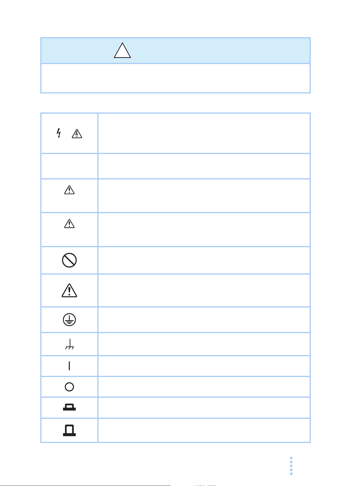
Safety Symbols
!
For the safe use and maintenance of this product, the following symbols are used
throughout this manual and on the product itself. Note the meaning of each of the
symbols to ensure safe use of the product. (Not all symbols may be used.)
Indicates that a high voltage (over 1 000 V) is used here.
or
Touching the part will result in a possibly fatal electric shock.
contact is required by your work, start work only after you make sure
that no voltage is output here.
If physical
DANGER
WARNING
CAUTION
Indicates an imminently hazardous situation which, if ignored, will result
in death or serious injury.
Indicates a potentially hazardous situation which, if ignored, could result
in death or serious injury.
Indicates a potentially hazardous situation which, if ignored, may result
in damage to the product and other property.
Shows that the act indicated is prohibited.
Indicates a general danger, warning, or caution.
When
this manual.
Protective conductor terminal.
this symbol is marked on the product, see the relevant sections in
Chassis (frame) terminal.
On (supply)
Off (supply)
In position of a bi-stable push control
Out position of a bi-stable push control
PCZ1000A iii
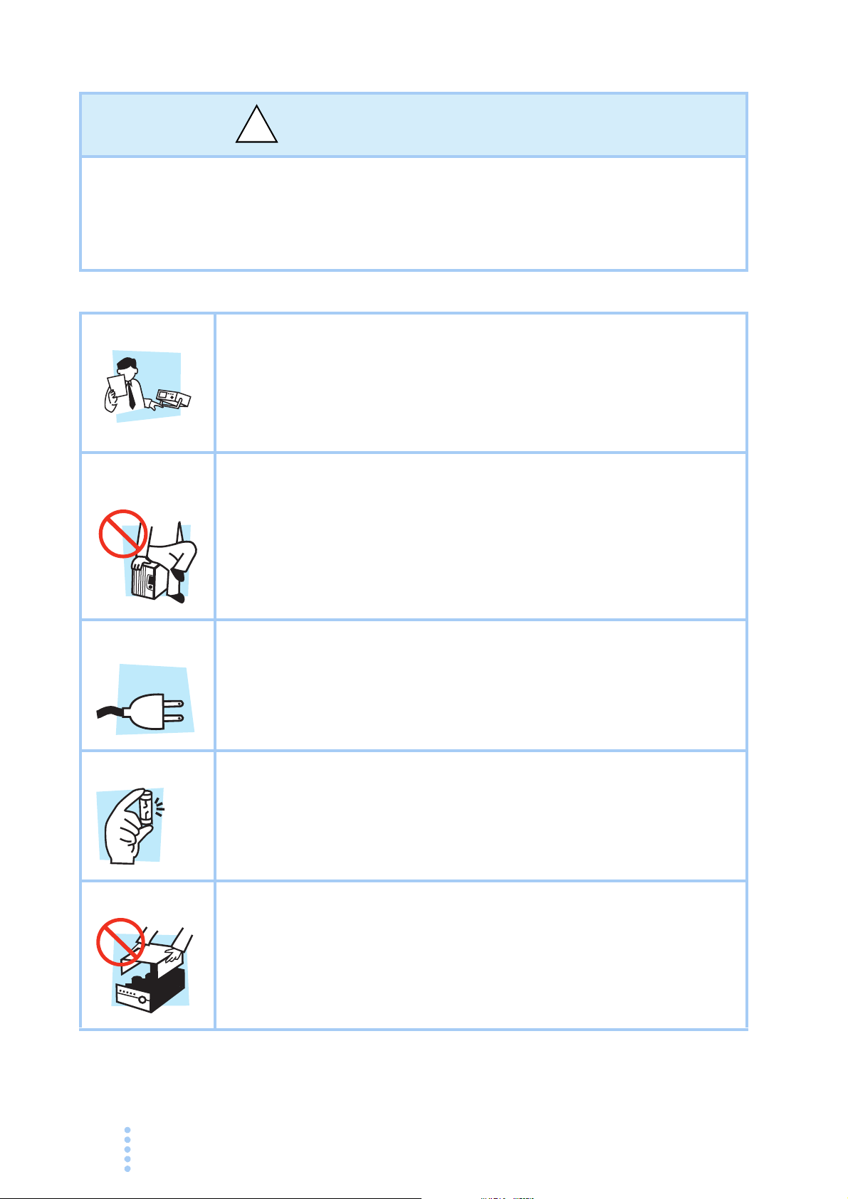
Safety Precautions
!
Operation
Manual
Line
Voltage
The following safety precautions must be observed to avoid fire hazards, electric
shock, accidents, and other failures. Please keep these in mind and follow the
instructions carefully.
may
Using the product in a manner that is not specified in this manual
protection functions provided by the product.
impair the
Users
Purpose of
use
Input power
• This product must be used only by qualified personnel who
understand the contents of this operation manual.
• If an unqualified person is to use the product, be sure the product is
handled under the supervision of qualified personnel (those who have
electrical knowledge). This is to prevent the possibility of personal
injury.
• Never use the product for purposes other than the product's intended
use.
• This product is not designed or manufactured for general home or
consumer use.
• Use the product within the rated input power voltage range.
• Use the power cord provided. For details, see the relevant page in the
operation manual.
• This product is a IEC Overvoltage Category II device (energy-
consuming
equipment supplied from the fixed installation).
Fuse
Cover
iv PCZ1000A
• The fuse can be replaced on this product. When replacing the fuse,
use a fuse with the correct shape, rating, and characteristics for the
product. For details, see the relevant page in the operation manual.
• Some parts inside the product may cause physical hazards. Do not
remove the external cover.
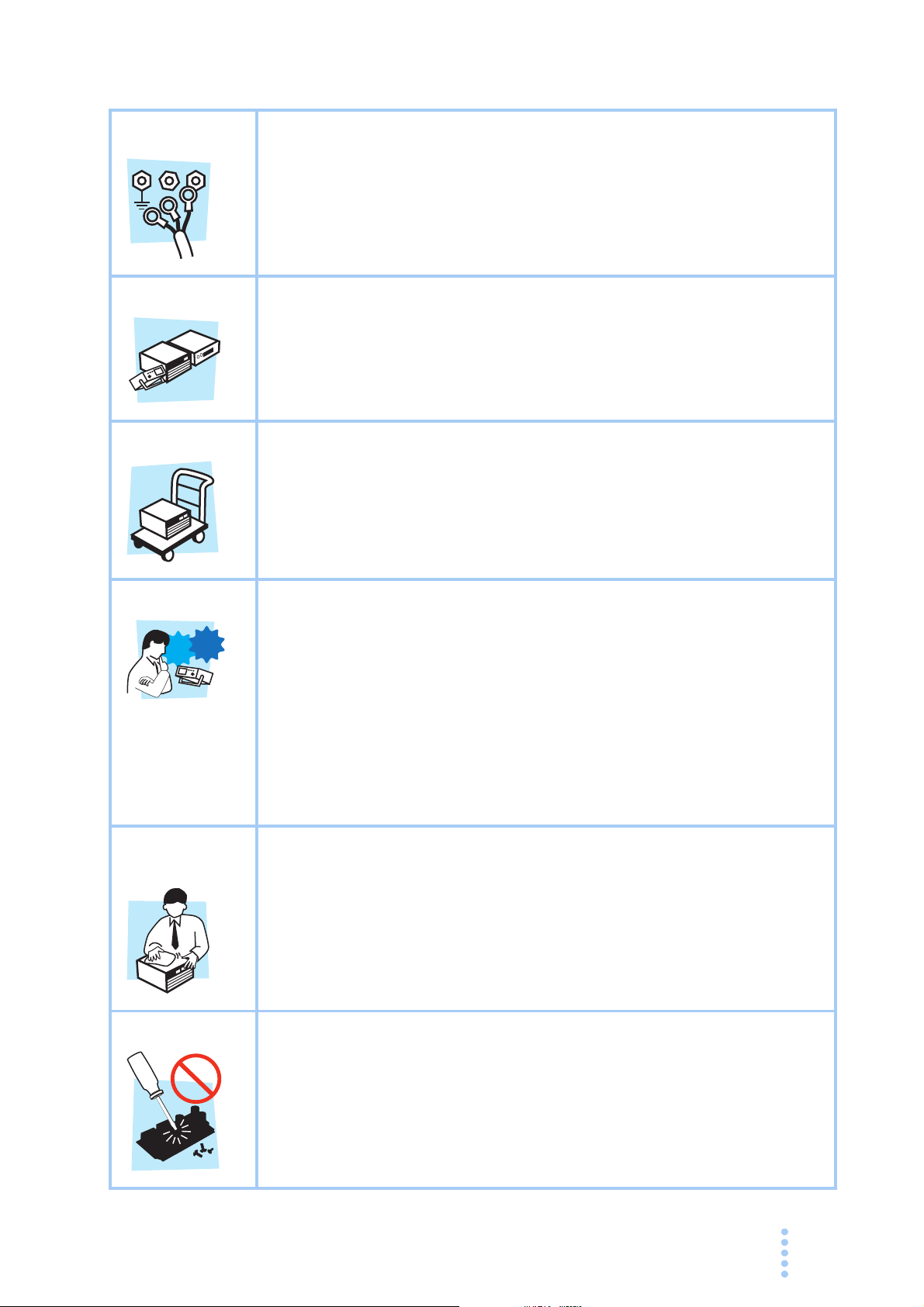
Grounding
G
N
L
Check?
• This product is an IEC Safety Class I device (device with protected
conductor terminals). To prevent electric shock, be sure to connect the
protective conductor terminal of the product to electrical ground
(safety ground).
Installation
Relocation
Operation
• This product is designed for safe indoor use. Only use the product
indoors.
• Please read the section 2.2, “Precautions for Installation” section of
this manual before installing the product and comply with the
instructions.
• Turn off the POWER switch, and disconnect the cables before
relocating the product.
• The product weighs over 20 kg. When moving the product, have more
than one person
rear panel of the product and in the specification table in this manual.
• When relocating the product, remember to also relocate the manual.
• Before using the product, be sure to check the input power voltage and
that there is no abnormality in the appearance of the AC power cord.
Be sure to remove the power cord plug from the outlet before checking.
• If a malfunction or abnormality is detected on the product, stop using
immediately, and remove the power cord plug from the outlet. Make
sure the product is not used until it is completely repaired.
• Use cables or wires with sufficiently large current capacity for output
wires and load cables.
carry it. The weight of the product is indicated on the
it
is
t
Maintenance
and inspection
Service
• Do not disassemble or modify the product. If you need to modify the
product, contact your Kikusui distributor or agent.
• To prevent electric shock, be sure to turn off the switchboard breaker
before carrying out maintenance or inspection.
• Do not remove the external cover during maintenance or inspection.
• To maintain the performance and safe operation of the product, i
recommended that periodic maintenance, inspection, cleaning, and
calibration be performed.
• Kikusui service engineers will perform internal service on the product.
If the product needs adjustment or repairs, contact your Kikusui
distributor or agent.
PCZ1000A v

How to Read This Manual
Introduction
Thank you for purchasing the PCZ1000A AC electronic load.
This manual is intended for first-time users of the PCZ1
of the PCZ1000A and describes various settings, program messages, maintenance,
and precautions, etc.
Read this manual thoroughly to use the functions of the PCZ1000A ef
can also review this manual when you are confused about an operation or when a
problem occurs.
How to read this manual
This manual is designed to be read from beginning to end. We recommend that you
read this manual thoroughly from the beginning before using the PCZ1000A for the
first time.
Intended readers of this manual
000A. It gives an overview
fectively. You
This manual is intended for users of the PCZ1000A or persons teaching other users
on how to operate the PCZ1000A.
The manual assumes that the reader has knowledge about electronic load equipments.
Information on the remote control c
reader has sufficient knowledge about controlling measuring instruments using a
personal computer.
ommands
are provided with the premise that the
vi PCZ1000A

Structure of this manual
See
This operation manual consists of the following chapters. The following outlines
each chapter.
1
Chapter 1 General Description
This chapter gives an overview and describes the features of the PCZ1000A.
Chapter 2 Unpacking and Installation
This chapter describes the necessary procedures from unpacking the product to
preparation before use.
Chapter 3 Operation
This chapter describes each mode and function of the operation.
Chapter 4 Remote Control
This chapter describes how to program the remote control features of the
PCZ1000A using an external device such as a personal computer. The explanation
covers the command syntax, details of each c
Chapter 5 Maintenance and Calibration
This chapter describes the maintenance procedures including cleaning, inspection,
and calibration.
Chapter 6 Specifications
This chapter gives the specifications and dimensions of the PCZ1000A.
Appendix
The appendix contains the basic operating modes, operating range, and
troubleshooting.
ommand, and the registers.
2
3
4
5
6
Appx.
Notation used in this manual
• The PCZ1000A AC electronic load is simply referred to as the PCZ1000A in this
manual.
• The term "computer" is used to refer to a personal
similar.
• The following markings are used in this manual.
W ARNING
CAUTION
SHIFT+key name (marked in blue)
computer, workstation, or
Indicates a potentially hazardous situation which, if ignored,
could result in death
Indicates a potentially hazardous
result in damage to the product and other property.
may
Indicates information that you shou
Explanation of terminology or operation principle.
Indicates a reference to detailed information.
Indicates an operation involving pressing the named key
(printed
illuminates after the SHIFT key is held down.
in blue) when the LED above the SHIFT key
or serious injury.
situation which, if ignored,
ld know.
PCZ1000A vii

Contents
Power Requirements of this Product - - - - - - - - - - - - - - - - - - - - - - - - - - - - - - - - - - - i
Safety Symbols - - - - - - - - - - - - - - - - - - - - - - - - - - - - - - - - - - - - - - - - - - - - - - - - iii
Safety Precautions - - - - - - - - - - - - - - - - - - - - - - - - - - - - - - - - - - - - - - - - - - - - - - iv
How to Read This Manual - - - - - - - - - - - - - - - - - - - - - - - - - - - - - - - - - - - - - - - - - vi
Contents - - - - - - - - - - - - - - - - - - - - - - - - - - - - - - - - - - - - - - - - - - - - - - - - - - - - - viii
Function Index - - - - - - - - - - - - - - - - - - - - - - - - - - - - - - - - - - - - - - - - - - - - - - - - - xi
Front panel - - - - - - - - - - - - - - - - - - - - - - - - - - - - - - - - - - - - - - - - - - - - - - - - - - - - xii
Rear panel - - - - - - - - - - - - - - - - - - - - - - - - - - - - - - - - - - - - - - - - - - - - - - - - - - - xiv
Chapter 1 General Description
1.1 About This Manual - - - - - - - - - - - - - - - - - - - - - - - - - - - - - - - - - - - - - - - - - 1-2
1.2 Product Overview - - - - - - - - - - - - - - - - - - - - - - - - - -
- - - - - - - - - - - - - - - - 1-2
1.3 Features - - - - - - - - - - - - - - - -
1.4 Options - - - - - - - -
- - - - - - - - - - - - - - - - - - - - - - - - - - - - - - - - - - - - - - - - - 1-3
- - - - - - - - - - - - - - - - - - - - - - - - - - - - - - - - 1-2
Chapter 2 Unpacking and Installation
2.1 Unpacking Checks - - - - - - - - - - - - - - - - - - - - - - - - - - - - - - - - - - - - - - - - - 2-2
2.2 Precautions for Installation - - - - - - -
2.3 Precautions for Moving - - - - - - - - - -
2.4 Attaching to the Rack Mount Frame - - - - - - - - - - - - - - - - - - -
2.5 Checking the Input Power and Fuse- - - - - - - - - - - - - - - - - - -
2.6 Connecting the AC Power Cord - - - - Procedure for Connecting the Power Cord
2.7 Load Wiring - - - - - - - - - - - - - - - - - - - - - - - - - - - -
2.7.1 Precautions Concerning Wiring- - - - - - - - - - - - - - - - - Overvoltage - - - - - - - - - - Other Precautions - - - - - - - - - - - - - - - - - - - - - - - - - - - - -
Input Voltage Waveforms - - - - - - - - - - - - - - - - - - - - - - -
2.7.2 Connection to the Load Input Terminals
- - - - - - - - - - - - - - - - - - - - - - - - - - - - 2-2
- - - - - - - - - - - - - - - - - - - - - - - - - - - - 2-4
- - - - - - - - - - 2-5
- - - - - - - - - - 2-6
- - - - - - - - - - - - - - - - - - - - - - - - - - - 2-8
- - - - - - - - - - - - - - - - - - - - - 2-8
- - - - - - - - - - - - - - - - - - 2-9
- - - - - - - - - 2-9
- - - - - - - - - - - - - - - - - - - - - - - - - - - - - - - 2-10
- - - - - - - - - 2-10
- - - - - - - - - - 2-11
- - - - - - - - - - - - - - - - - - - 2-13
Chapter 3 Operation
3.1 Basic Panel Operation - - - - - - - - - - - - - - - - - - - - - - - - - - - - - - - - - - - - - - 3-2
Function Keys - - - - - - - - - - - - - - - - - - - - - - - - - - - - - - - Preset Memory Key - - - - - - - - - - - - - - - - - - - - - - - - - - - -
Other Keys - - - - - - - - - - - -
3.2 Turning On the Power- - - - - - - - - - -
3.3 Load-On/Load-Off - - - - - - - - - -
3.4 Protection Functions and Alarms - - - - - - - - - - - - - - - Alarm Occurrence and Release - - - - - - - - - - - - - - - - - - - Protection Functions - - - - - - - - - - - - - - - - - - - - - - -
3.5 Operation Modes - - - - - - - - - - - - - Operation Mode Display - - - - - - - - - - - - - - - - - - - - - - - -
viii PCZ1000A
- - - - - - - - - - - - - - - - - - - - - - - - - - - - - - - - 3-4
- - - - - - - - - - - - - - - - - - - - - - - - - - - - 3-5
- - - - - - - - - - - - - - - - - - - - - - - - - - - - - - - 3-6
- - - - - - - - - - - - - - - 3-7
- - - - - - - - - - - - - - - - - - - - - - - - - - - 3-10
- - - - - - - - - - 3-2
- - - - - - - - - - 3-3
- - - - - - - - - 3-7
- - - - - - - - - - - - - - 3-7
- - - - - - - - - 3-10

3.5.1 CC Mode Operation - - - - - - - - - - - - - - - - - - - - - - - - - - - - - - - - - 3-11
3.5.2 Constant Resistance (CR) Mode - - - -
3.5.3 Constant Power (CP) Mode - - - -
3.5.4 Crest Factor Function - - - -
- - - - - - - - - - - - - - - - - - - - - - - - - - - - 3-16
- - - - - - - - - - - - - - - - - - - - 3-12
- - - - - - - - - - - - - - - - - - - - - - - - 3-15
1
3.6 Saving and Recalling Preset Memory - - - - - - - - - - - - -
Saving Preset Memory - - - - - - - - - - - - - - - - - - - - - - -
Changing Preset Memory - - - - - - - - - - - - - - - - - - - - - - - - - - - - - - - - 3-19
Recalling Preset Memory - - - - - - - - - - - - - - - - - - - - -
3.7 Parallel Operation and Tracking Operation - - - - - - - - - - - - -
3.7.1 Configuration (CONFIG) Settings - - - -
How to Display and Set Configuration Sett
3.7.2 Parallel Operation - - - - - - -
Procedure for Connecting Units in Parallel-
Procedure for Setting Master and Slave Units - - - - - - - - - - - - - - - - - - 3-25
3.7.3 Tracking Operation - - - - - - - - - -
Connecting Units for Tracking Operation - - - - - - - - - - - - - - Procedure for Setting Master and Slave
3.7.4 Calibration of the Ammeter on the M
3-30
Preparation for Calibration - - - - - - - - - - - - - - - - - - - -
Calibration Procedure - - - - - - - - -
3.7.5 Alarms During Parallel and Tracking Operation - - - - - - - - - - - - -
3.7.6 Returning to Standalone Operation - -
3.8 Factory Default Settings - - - - - - -
- - - - - - - - - - - - - - - - - - - - - - - - - - - - 3-23
- - - - - - - - - - - - - - - - - - - - - - - - - - 3-31
- - - - - - - - - - - - - - - - - - - - - - - - - - - - - 3-34
- - - - - - - - - - - - - - - - - - - - 3-21
ings - - - - - - - - - - - - - - - - - 3-22
- - - - - - - - - - - - - - - - - - - - 3-24
- - - - - - - - - - - - - - - - - - - - - - - - 3-27
Units - - - - - - - - - - - - - - - - - - 3-28
aster Unit During Parallel Operation
- - - - - - - - - - - - - - - - - - - - 3-33
- - - - - - - - - - - - - 3-17
-
- - - - - - - - - - - 3-18
- - - - - - - - - - - 3-20
- - - - - - - - - - 3-21
- - - - - - - 3-28
- - - - - - - - - - 3-30
- 3-33
2
3
4
5
6
Appx.
Chapter 4 Remote Control
4.1 Overview of Remote Control - - - - - - - - - - - - - - - - - - - - - - - - - - - - - - - - - - 4-2
4.1.1 RS232C Interface - - - - - - -
4.2 Programming Format - - - - - - - - - -
4.2.1 Program Messages- - - - - - - - - -
4.3 Device Messages - - - - - - - - - - - - - - - - - - - - - - - - - -
4.3.1 Program Header and Program (Response) Da
4.3.2 Configuration of Device Messages - - -
Basic Messages - - - - - - - - - -
System Messages- - - - - - - - - Communication Settings and Control Codes - - - - - - - - - - - - - -
4.4 Assignment of Register Bits - - - - - - - - - - - - - - - - - Fault Register - - - - - - - - - - - - - - - - - - - - - - - - - - - - Fault Register 2 - - - - - - - - - - - - - - - - - - - - - - - - - - - Error Register - - - - - - - - - - - - - - - - - - - - - - - - - - - - Communication Command Errors - - - - - - - - - - - - - - - - - - - - - - - - -
- - - - - - - - - - - - - - - - - - - - - - - - - - - - - 4-2
- - - - - - - - - - - - - - - - - - - - - - - - - - - - - 4-4
- - - - - - - - - - - - - - - - - - - - - - - - - 4-4
- - - - - - - - - - - - - - - 4-5
ta - - - - - - - - - - - - - - 4-5
- - - - - - - - - - - - - - - - - - - - - 4-6
- - - - - - - - - - - - - - - - - - - - - - - - - - - - - - 4-6
- - - - - - - - - - - - - - - - - - - - - - - - - - - - - 4-8
- - - - - - 4-8
- - - - - - - - - - - - - - - - 4-9
- - - - - - - - - - - - 4-9
- - - - - - - - - - - - 4-9
- - - - - - - - - - - 4-10
Chapter 5 Maintenance and Calibration
5.1 Cleaning and Inspection - - - - - - - - - - - - - - - - - - - - - - - - - - - - - - - - - - - - - 5-2
Inspecting the Power Cord - - - - - - Cleaning the Panel - - - - - - - - - - -
- - - - - - - - - - - - - - - - - - - - - - - - - 5-2
- - - - - - - - - - - - - - - - - - - - - - - - - - - 5-2
- 4-10
PCZ1000A ix

Replacing the Backup Battery - - - - - - - - - - - - - - - - - - - - - - - - - - - - - - 5-2
Cleaning the Dust Filter - - - - - - - -
5.2 Calibration - - - - - - - - - - - - - - - - - - - - - - - - - - - - -
- - - - - - - - - - - - - - - - - - - - - - - - - - - 5-2
- - - - - - - - - - - - - - - - - - 5-3
Chapter 6 Specifications
6.1 Specifications- - - - - - - - - - - - - - - - - - - - - - - - - - - - - - - - - - - - - - - - - - - - - 6-2
6.2 Dimensions - - - - - - - - - - - - - - - - - - - - - - - - - - - -
- - - - - - - - - - - - - - - - - - 6-5
Appendix
A.1 Explanation of Operating Functions - - - - - - - - - - - - - - - - - - - - - - - - - - - - - A-2
A.1.1 Operating Functions - - - - - - -
Operating Range - - - - - - - - - - - - - - - - - - - - - - - - - Differences Between DC and AC Loads -
A.1.2 Explanation of Operating Mode- - - -
Constant-Current (CC) Mode - - - -
Constant-Resistance (CR) Mode- - - - - -
Constant-Power (CP) Mode - - - - - - - - - - - - - - - - - - - - - - - - - - - - - - - A-6
- - - - - - - - - - - - - - - - - - - - - - - - - - - A-2
- - - - - - - - - - - - - A-2
- - - - - - - - - - - - - - - - - - - - - - A-2
- - - - - - - - - - - - - - - - - - - - - - - A-4
- - - - - - - - - - - - - - - - - - - - - - - - - - - A-4
- - - - - - - - - - - - - - - - - - - - - - A-5
A.2 Troubleshooting - - - - - - - - - - - - - - -
Index
- - - - - - - - - - - - - - - - - - - - - - - - - - - - A-7
x PCZ1000A
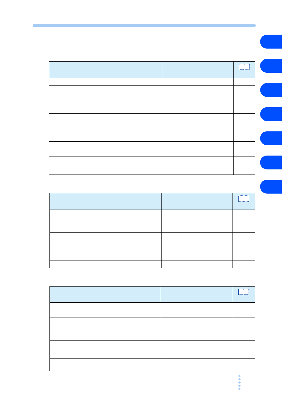
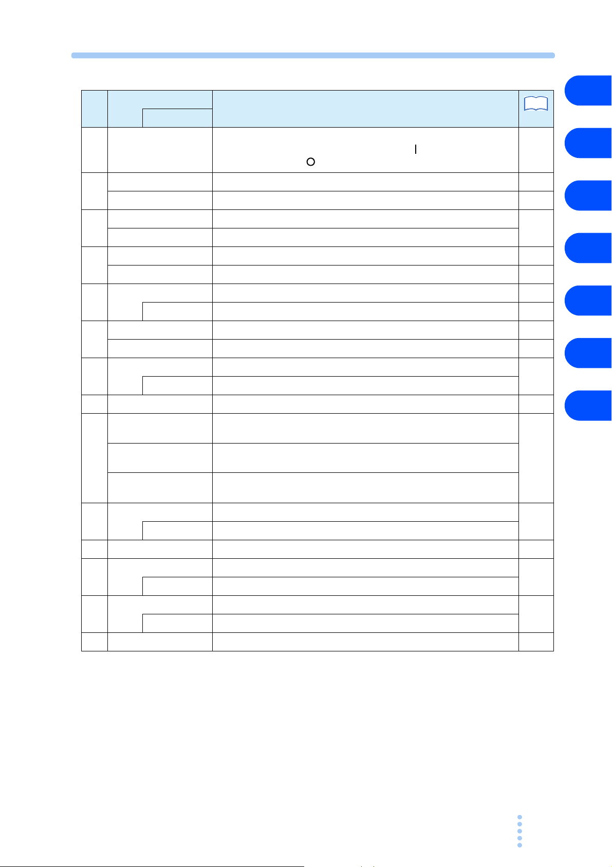
Function Index
See
See
Preparation
1
Topic Section in the Manual
How do I check that all accessories are included. Unpacking Checks 2-2
What precautions should I observe when installing? Precautions for Installation 2-2
What precautions should I observe regarding grounding? Connecting the AC Power Cord 2-8
What precautions should I observe regarding the load
unit?
How do I connect the power cord? Connecting the AC Power Cord 2-8
How do I connect the load? Connection to the Load Input
Where do I find detailed explanation of initial settings? Turning On the Power 3-5
How do the protection functions work? Protection Functions and Alarms 3-7
What settings are available? Basic Panel Operation 3-2
What are the connector requirements and what is the
procedure for connecting PCZ1000A units to operate in
parallel?
Load Wiring
Terminals
Procedure for Connecting Units in
Parallel 3-24
See
Page
2-9
2-13
Operation
Topic Section in the Manual
How do I turn the power on and off? Turning On the Power 3-5
How do I set the protection functions? Protection Functions and Alarms 3-7
How do I use the PCZ1000A in constant-current mode? CC Mode Operation 3-11
How do I use the PCZ1000A in constant-resistance
mode?
How do I use the PCZ1000A in constant-power mode? Constant Power (CP) Mode 3-15
How do I use the Crest Factor function? Crest Factor Function 3-16
How do I set the configuration (CONFIG)? Configuration (CONFIG) Settings 3-21
Constant Resistance (CR) Mode
Page
3-12
2
3
4
5
6
Appx.
Others
To pi c Section in the Manual
How can I check whether the PCZ1000A is faulty? Troubleshooting
How do I perform troubleshooting?
Where do I find detailed command reference? Programming Format 4-4
What do the remote control error messages mean? Assignment of Register Bits 4-9
How do I perform maintenance? Cleaning and Inspection 5-2
What is the procedure for calibration? Calibration of the Ammeter on the
Master Unit During Parallel
Operation
How do I reset the PCZ1000A to the factory default
settings?
PCZ1000A xi
Factory Default Settings
Page
A-7
3-30
3-34
18
17
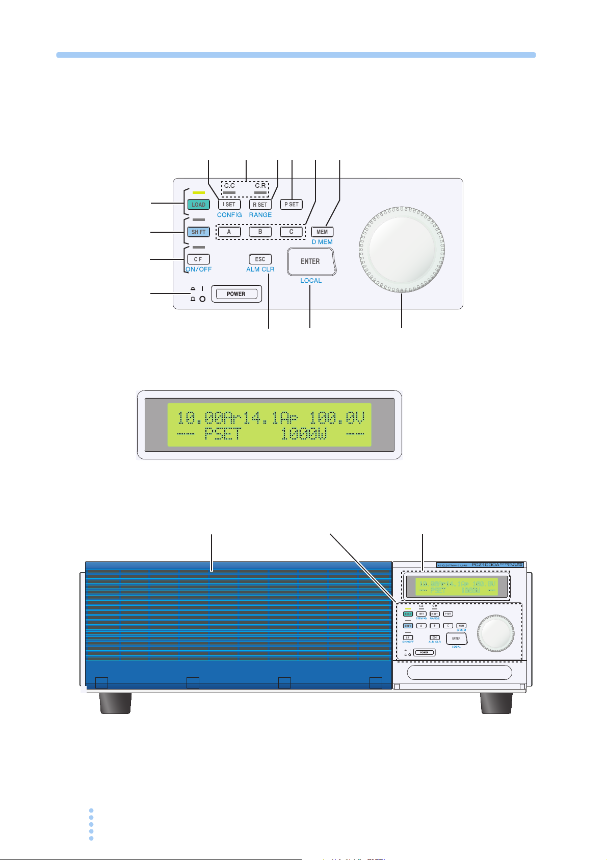
Control panel
Control panel
1
Display
Display
2
3
4
5
67
8
9
10
11
1213
14
Front panel
xii PCZ1000A
No.
See
POWER Power on/off switch
1
C.F ON/OFF Turns CF mode on or off. 3-3
2
C.F LED Illuminates to indicate when CF
SHIFT Enables keys indicated in blue.
3
SHIFT LED Illuminates to indicate when the SHIFT key is active.
LOAD ON/OFF Turns the load on or off. 3-2
4
LOAD LED Illuminates to indicate when the lo
Name
Explanation
The power is ON when the switch is in
switch is out position ( ).
mode is on. 3-10
ad is on. -
position ( ) and OFF when the
Page+SHIFT
3-5
1
2
3
-
4
I SET Sets CC mode and to set the current l
5
CONFIG Specifies various settings that control the operation. 3-21
C.C LED Illuminates to indicate when CC or CP mode is on. 3-10
6
C.R LED Illuminates to indicate when CR or CP mode is on. 3-10
R SET Sets CR mode and to set the resistance limit using the rotary knob.
7
RANGE Range selection key
P SET Sets CP mode and to set the power limit using the rotary knob. 3-3
8
A Recalls the preset memory A value; pressing the MEM key and A saves
9
B Recalls the preset memory B value; pressing the MEM key and B saves
C Recalls the preset memory C value; pressing the
MEM Saves preset memory values.
10
D MEM Modifies preset memory values.
Rotary knob Fine and coarse adjustment of setting values 3-2
11
ENTER Enter key for preset memory
12
LOCAL Local operation selection key
the value to preset memory A.
the value to preset memory B.
the value to preset memory C.
imit using the rotary knob. 3-2
MEM key and C saves
5
6
3-3
Appx.
3-3
3-3
3-4
ESC Cancels the selected function.
13
ALM CLR Clears an alarm.
Ventilation louvers Provides ventilation for the unit. Fitt
14
PCZ1000A xiii
ed with an internal dust filter. 5-2
3-4
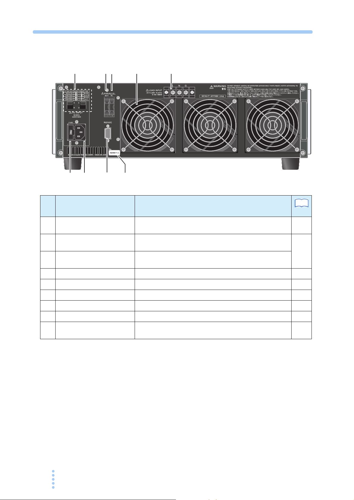
Rear panel
1
8
23
4
5
6
7
9
No. Name Explanation
Power supply voltage range
1
selection switch
PARALLEL OUT Connector for parallel operation (output). Incorporates a
2
PARALLEL IN Connector for parallel operation (input). Incorporates
3
Ventilation outlets Cooling ventilation outlets 2-3
4
LOAD INPUT Load input terminals 2-9
5
Serial number The serial number of the instrument -
6
RS232C RS232C connector used by the remote control fu
7
AC INPUT AC power supply inlet 2-8
8
FUSE Power supply fuse holder, includes a spare fuse (1) 2-2,
9
Switch for selecting the power supply voltage to be used
protective socket.
a protective
socket.
nction 4-2
See
Page
2-6
3-23
2-7
xiv PCZ1000A

General Description
This chapter gives an overview and describes the features of
the PCZ1000A.

1.1 About This Manual
See
This operation manual describes the PCZ1000A AC electronic load.
Applicable firmware versions
page 3-5
This manual applies to PCZ1000A with firmware version 1.4x.
When making an inquiry about the product, please provide us with the following
information:
• Mo
del Name (PCZ1000A)
• Firmware version
• Serial number (indicated at the lower section on the rear panel)
1.2 Product Overview
The PCZ1000A is an AC electronic load featuring high reliability and safety. In
addition to the resistive loads generally used in tests, it is capable of simulating
capacitive-input rectifier loads.
1.3 Features
● Crest-factor function
In addition to the constant-current*, const
modes, the PCZ1000A also features a crest-factor function which is useful for
load testing of peak or harmonic currents. This helps reduce design and labor
time and cost as well as improve the quality of the equipment under test.
* The instrument always allows a current waveform close to a sine waveform to
flow unaffected by the voltage waveform.
Simple operation
●
The key features can be operated quickl
adjustment is possible with the rotary knob.
● Easy-to-see LCD with backlight
The instrument features an LCD with
operations to be performed. Test results are displayed clearly and are unaffected
by ambient light.
● Parallel operation
Up to five units can be used in parallel under the control of a single master unit.
PCZ1000A can be set as a master and up to four slave PCZ1000As connected in
parallel (max. 5 kW, 50 Arms). The total power is displayed on the front panel of
the master unit.
ant-resistance*, and constant-power*
y on a one-key-to-one-feature basis. Fine
LED backlight, enabling a variety of
A
1-2 PCZ1000A
● Tracking operation
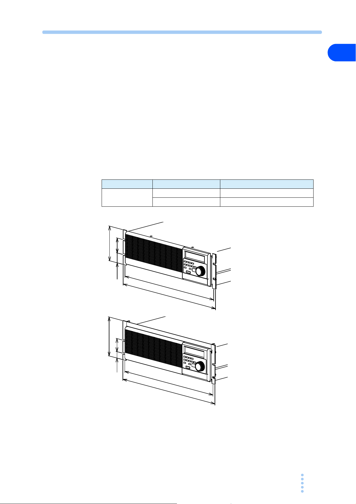
KRB3
KRB150
Unit: mm
57
463
482
132.5
37.75
5024.5
149
460
480
Up to five units can b
Setup values specified on the master
any changes to the master unit settings are also applied immediately to the
slaves. Useful for testing single-phase/three-wire or three-phase/three-wire AC
power supply loads.
1.4 Options
The following options are available for the PCZ1000A.
For details on the options, contact your Kikusui agent or distributor.
■ Rack mounting option
Part Name Model No. Remarks
Rack mounting
bracket
e tracked
unit are also applied to the slave units and
KRB3 For EIA standard inch units racks
KRB150 For JIS standard metric units racks
1
General Description
PCZ1000A 1-3

■ Signal cable for parallel operation
Cable used for parallel operation
Part name Model No. Remarks
Signal cable for
parallel operation
PC01-PCZ1000A 300 mm, 10-pin
1-4 PCZ1000A

Unpacking and Installation
This chapter describes the necessary procedures from
unpacking the product to preparation before use.
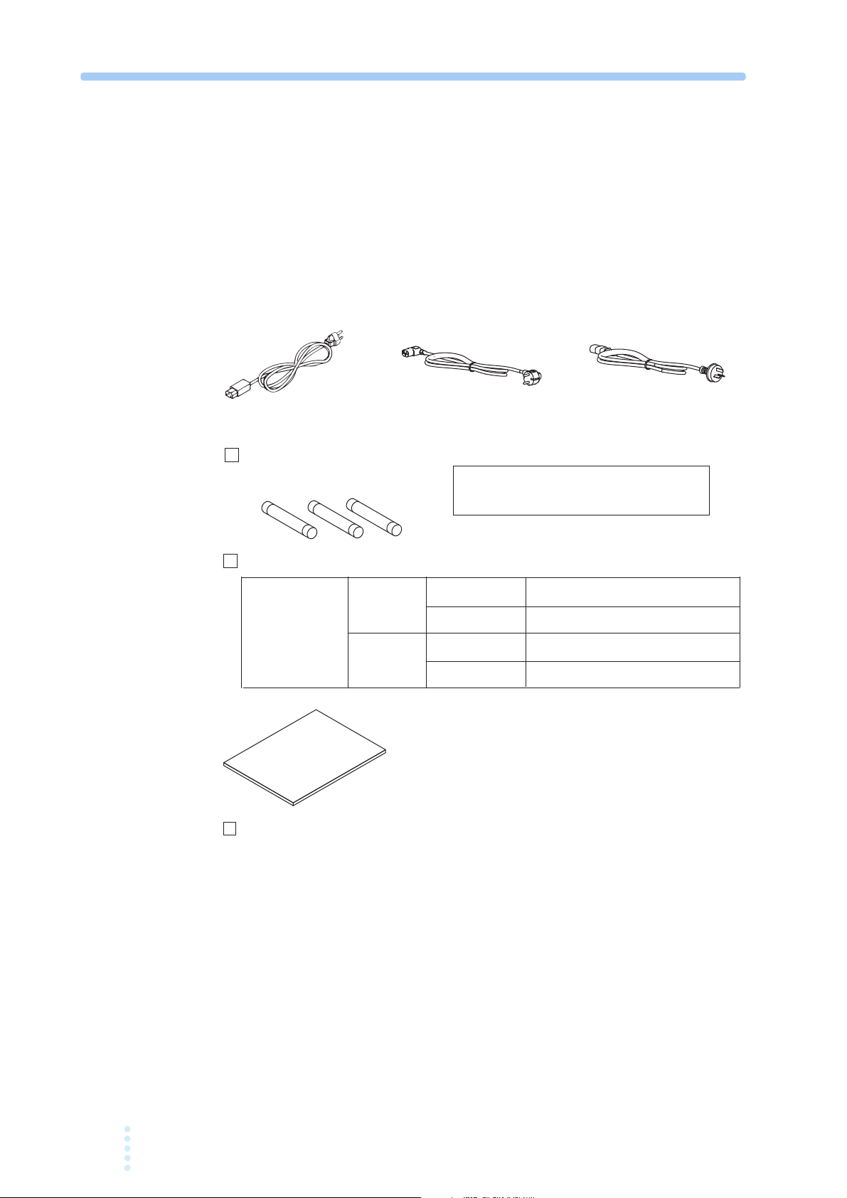
2.1 Unpacking Checks
For 100 V
system
For 200 V
system
[Z1-004-002]
Spare fuses (3 pcs.)
Power cord (1 pc.)
In AC inlet 100 V, 3.15A (1 pc.) [99-02-0037]
Also supplied 200 V, 2A (2 pcs.) [99-00-0026]
In AC inlet 200 V, 2A (1 pc.) [99-00-0026]
Also supplied 100 V, 3.15A (2 pcs.) [99-02-0037]
Line input voltage
range set when
the instrument
was shipped
The supplied power cord and spare fuses are
different depending on the line input voltage
range set when the instrument was shipped.
[85-AA-0004] [85-10-0840]
Rated voltage: 125 Vac
PLUG: NEMA5-15
Rated voltage: 250 Vac
PLUG: CEE7/7
[85-10-0790]
Rated voltage: 250 Vac
PLUG: GB1002
or or
Upon receiving the PCZ1000A, make sure the package contains all the necessary
parts and that the PCZ1000A has not been damaged during transportation. If you
find any damage or other problems, please contact your Kikusui distributor or agent.
We recommend that all packing materials are saved, in case the product needs to be
transported at a later date.
Accessories
2.2 Precautions for Installation
Manual (1 copy)
Be sure to observe the following precautions when installing the product.
● Do not use the PCZ1000A in a flammable atmosphere.
To prevent explosion or fire, do not use the product near alcohol, thinner,
other combustible materials, or in an atmosphere containing such vapors.
2-2 PCZ1000A
Fig.2-1 Accessories
or

● Avoid locations where the PCZ1000A is exposed to high temperatures or
direct sunlight.
Do not locate the product near a heater or in areas subject to drastic temperature
changes
● Avoid humid environments.
.
Operating temperature range: 0 °C to 40 °C (32 °F to
Storage temperature range: -25 °C to 70 °C (-13 °F to 15
10
4 °F)
8 °F)
2
Do not locate the PCZ1000A in a high-humidity environment near a b o
humidifier, or water supply.
Operating humidity range: 20 %rh to 85 %rh (no condensation)
Storage humidity range: 90 %rh or less (no condensation)
Condensation may occur even within
the operating humidity range. In that case,
do not start using the product until the location is completely dry.
● Be sure to use the PCZ1000A indoors.
This PCZ1000A is designed for safe indoor use.
● Do not place the PCZ1000A in a corrosive atmosphere.
Do not install the product in a corrosive atmosphere or one containing sulf
mist or the like. This may cause corrosion of various conductors and imperfect contact
with connectors, leading to malfunction and failure or, in the worst case, a fire.
● Do not locate the PCZ1000A in a dusty environment.
Dirt and dust in the product may cause ele
● Do not use the PCZ1000A where ventilation is poor.
Secure adequate space around the product so that air can circula t e
ctrical shock or fire.
a r o u n d i t .
Allow at least 20 cm of space between the air inlet/outlet and the wall (or
obstacles).
i l e r ,
Unpacking and Installation
uric acid
● Do not place any object on the PCZ1000A.
In particular, do not place heavy objects on the product as this co
uld result in a
malfunction.
● Do not place the PCZ1000A on a tilted surface or in a location subject to
vibrations.
If placed on a non-level surface or in a location subject to vibratio
he product
n, t
may fall, resulting in damage and injury.
● Do not stand the PCZ1000A in upright position.
It may cause injury to the operator or t
he damage to the product when it falls
down.
● Do not use the PCZ1000A in a location where strong magnetic or electric
fields are present or with an input power supply with significant waveform
distortion or noise.
The PCZ1000A may malfunction.
● Use the PCZ1000A in an industrial environment.
The PCZ1000A may cause interference if used in residential areas. Suc
h use
must be avoided unless the user takes special measures to reduce
electromagnetic emissions to prevent interference to the reception of radio and
television broadcasts.
PCZ1000A 2-3

2.3 Precautions for Moving
When moving or transporting the PCZ1000A to an installation site, observe the
following precautions.
● Turn off the POWER switch.
Moving the PCZ1000A with the power on
● Remove all wiring.
Moving the PCZ1000A with cables connected ma
injuries due to the product falling over.
● The PCZ1000A should always be moved by more than one person.
The PCZ1000A should be relocated by no less than two persons. Take extra c
when placing the unit on a tilted or uneven surface. Never lay the unit on its side
or turn it upside down.
● When transporting the PCZ1000A, be sure to use the original packing
material.
Transport the PCZ1000A in its original package to prevent vibrat
which may damage the PCZ1000A.
● Be sure to include this manual.
may result in electrical shock or damage.
y cause wires to break or
are
n a n d f a l l s ,
i o
2-4 PCZ1000A
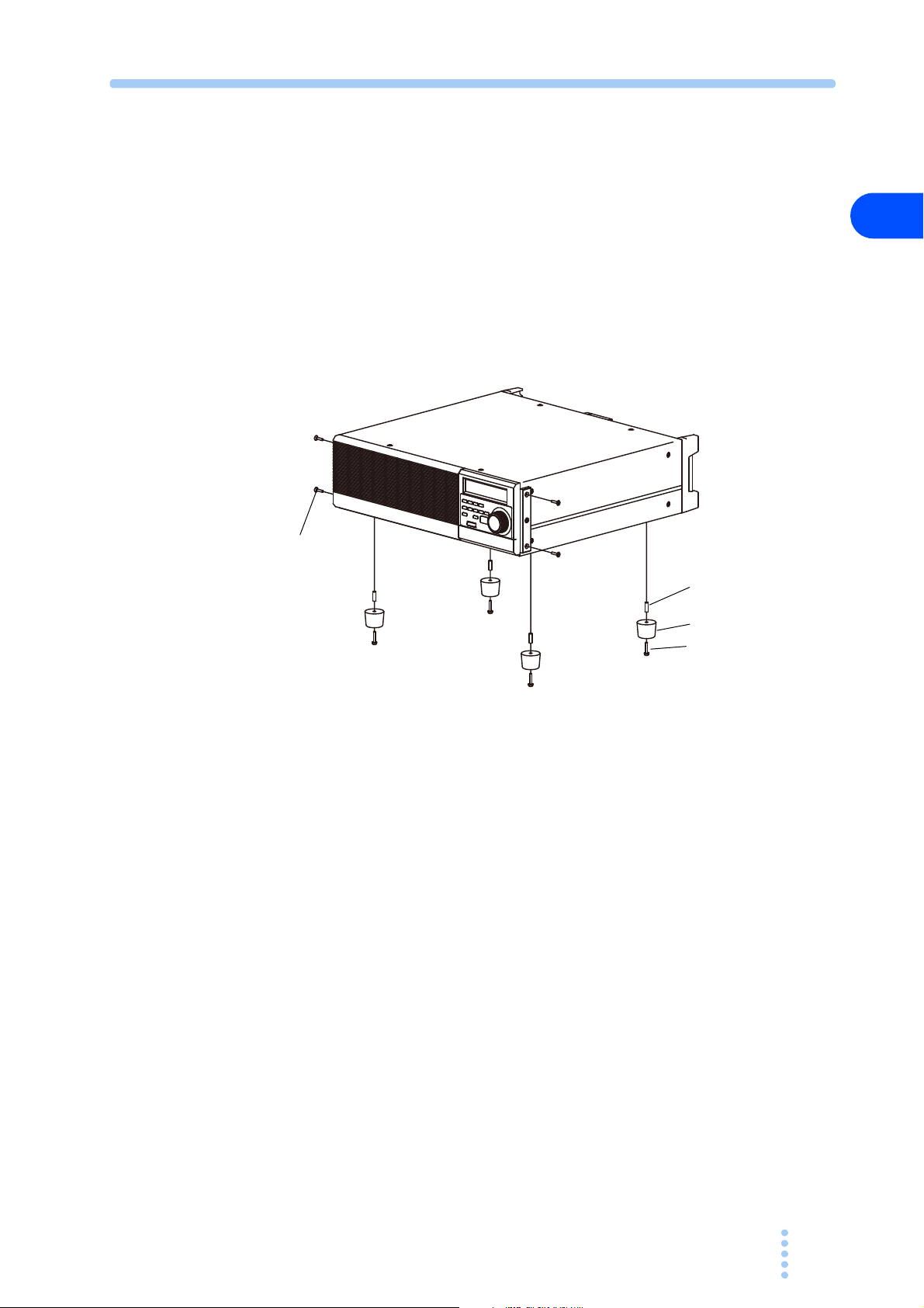
2.4 Attaching to the Rack Mount Frame
(4 locations)
Collar (4 locations)
Before installing the rack mount frame, remove the four M4 screw s a n d r u b b e r f e e t .
Fig.2-2 shows how to remove the rubber feet.
Refer to the KRB3 and KRB150 user guides for details about how to attach to the
rack.
We recommend that you keep all the parts so that you can use them again when you
detach the product from the frame.
To reattach the rubber feet, use the screws that you removed.
M4 screws
(4 locations)
2
Unpacking and Installation
Fig.2-2 How to Remove the Rubber Feet
How to remove the rubber feet
Undo the screws and remove the four rubber feet.
Rubber feet (4 locations)
Screws for attaching feet
PCZ1000A 2-5

2.5 Checking the Input Power and Fuse
W ARNING
CAUTION
VOLTAGE SELECT SWITCH POSITION FUSE
90-110V A C AC250V
108-132V B C 3.15A(T)
180-220V A D AC250V
216-250V B D 2A(T)
A C
B D
The PCZ1000A is used by selecting one of the four input line voltage ranges shown
in Fig.2-3. Check that the factory default setting is correct for the AC line input
voltage you will be using. Also, ensure that the line fuse is properly rated for the AC
line supply.
• To avoid electric shock, always unplug the AC power cord before
checking or replacing the fuse.
• Select replacement fuses of the same type, rating, and characteristic
those provided with the PCZ1000A. Using a fuse with an incorrect rating
or using the PCZ1000A with the fuse holder short-circuited may damage
the PCZ1000A.
Follow the procedure below to check or change the voltage input range and to check
or replace the line input fuse:
s as
1 Turn OFF the POWER switch.
2 Disconnect the AC power cord from the PCZ1000A.
3 Confirm that the position of voltage range selection switch on the rear
panel of the PCZ1000A matches the line input voltage to be used.
To change the settings, set the SWITCH POSITION as shown in Fig.2-3.
Use a flathead screwdriver to change t
he voltage settings.
2-6 PCZ1000A
Fig.2-3 Input Voltage Range Selection Switch
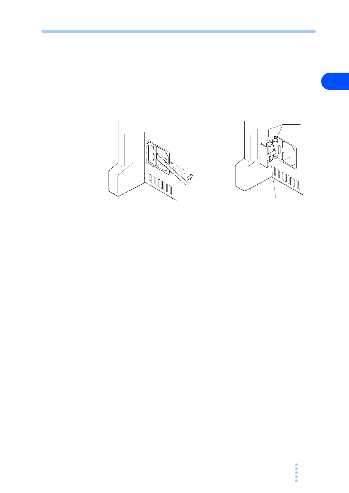
4 Insert the screwdriver as shown in Fig.2-4.
Spare
Fuses
5 Move the screwdriver in the direction indicated by the arrow to lever the
fuse holder out of the PCZ1000A.
6 Confirm that the rating of the installed fuse is appropriate for the line
voltage to be used. Also check that the time-current characteristics are
appropriate for the application.
Always replace with the correct fuse.
Fig.2-4 Removing the Fuse Holder
2
Unpacking and Installation
PCZ1000A 2-7

2.6 Connecting the AC Power Cord
W ARNING
To a three-prong outlet
with proper grounding
• The PCZ1000A is an IEC Safety Class I equipment (equipment with
protected conductor terminals). To prevent electric shock, be sure
to ground (earth) the unit.
• This unit is grounded through the ground wire of the power cord. Be
sure to connect the power plug to an outlet with an appropriate
earth ground.
• Use the supplied AC cable to connect to the AC power line. If the supplied cable
cannot be used because the rated voltage is different or the plug does not fit the
socket, have a qualified electrician replace it with a suitable cable no more than 3 m
in length. Please contact your local Kikusui agent or distributor if you have any
difficulty in obtaining a suitable power supply cable.
• The power cord and plug can be used to disconnect the unit from
line in case of emergency. Always plug the cable into a convenient nearby socket
from which you can unplug it quickly if necessary and provide sufficient space
around the socket.
• Please do not use the supplied power cord on any other equipment.
the AC
power
The PCZ1000A is an IEC Overvoltage Category II device (energy-consuming
equipment supplied from the fixed installation).
Procedure for Connecting the Power Cord
1 Turn off the POWER switch.
2 Check that the AC power line is compatible with the input power ratings
of the PCZ1000A.
The PCZ1000A can be used with power supplies with voltages between 100 Vrms and
240 Vrms, and with a frequency of 50 Hz or 60 Hz.
3 Connect the AC cable to the AC inlet (AC LINE) on the rear panel and
plug the other end to an outlet with proper grounding.
2-8 PCZ1000A
Fig.2-5 Grounding

2.7 Load Wiring
W ARNING
To ensure that the functions of the PCZ1000A work accurately and reliably, all
wires must be connected correctly to their loads.
2.7.1 Precautions Concerning Wiring
Electric wire used
• Risk of fire. Ensure that the cables used to connect the PCZ1000A to
the equipment under test have sufficient current-carrying capacity
compared to the rated input current of the PCZ1000A.
• Risk of electric shock. To ensure sufficient insulation compared to
the isolation voltage ±500 Vdc, use a reinforced insulation cable
(UL1032 cable or equivalent) for the cables used to connect the
PCZ1000A to the equipment under test.
See Table 2-1 for details of the cables to use to connect to the l o a d i n p u t t e r m i n a l s ,
and ensure that the cross-section area of the cables is adequate to carry the allowable
current recommended by Kikusui over and above the actual current l e v e l t o b e u s e d .
Also, please use cables with insulation able to withstand temperatures of 75 °C or
higher.
2
Unpacking and Installation
Table 2-1 Nominal Cross-Section Area and Allowable Current for
Cabling
Nominal Cross-
Section Area
2
]
[mm
2 14 (2.08) 27 10
3.5 12 (3.31) 37 -
5.5 10 (5.26) 49 20
8 8 (8.37) 61 30
14 6 (13.3) 88 50
22 4 (21.15) 115 80
30 2 (33.62) 139 -
38 1 (42.41) 162 100
50 1/0 (53.49) 190 -
60 2/0 (67.43) 217 -
80 3/0 (85.01) 257 200
100 4/0 (107.2) 298 -
125 - - 344 -
150 - - 395 300
200 - - 469 400
AWG
(Reference
cross-section
area)
2
]
[mm
Allowable
Current
(Ta = 30 °C)
*1
[A]
Current
Recommended
by Kikusui [A]
*1. Excerpts from Japanese laws related to electrical equipment.
PCZ1000A 2-9
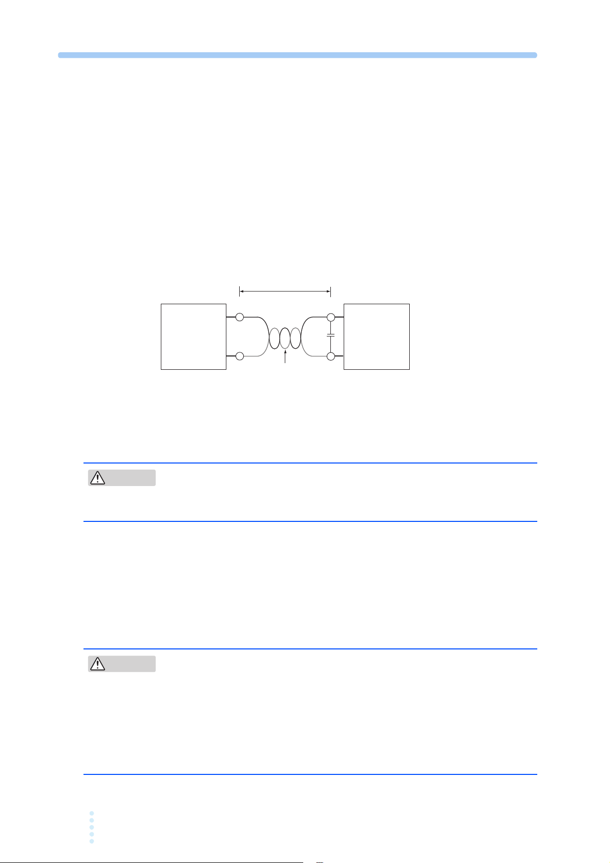
■ Load wire inductance
Equipment
under test
PCZ1000A
Short, 100 cm or less
Twist
L
C
Example: C=0.1 μF to 0.47 μF
N
CAUTION
CAUTION
If the load wire is long or has a large loop, the wire induct
ance is increased.
In such condition, the input voltage may fall below the minimum operating voltage
of the PCZ1000A causing the current waveform to be distorted. In some cases, the
input voltage may exceed the maximum input voltage and cause damage to the
PCZ1000A. The phase lag of the current may cause instability in the PCZ1000A
control inducing oscillation.
Connect the PCZ1000A and the equipment under test using the shortest twisted wire
possible to keep the voltage caused by inductance within the minimum operating
voltage and maximum input voltage rauge.
A capacitor may be connected to the load input terminual as shown in Fig.2-6 to
alleviate oscillation. In this case, use the capacitor within its allowable ripple
current.
Fig.2-6 Wiring Length
Overvoltage
• Risk of damage to the instrument. The maximum input voltage is 400
Vpeak. Do not apply voltages exceeding the maximum voltage of 400
Vpeak to the load input terminals.
The maximum voltage that can be applied to the load input termin a l s i s 4 0 0 V p e a k .
The PCZ1000A cannot be used with voltages higher than this.
If an excessive voltage is applied, an alarm will be displayed, a w a r n i n g s o u n d e d ,
and the load disconnected. Please reduce the voltage of the equipment under test.
Other Precautions
• The L and N load input terminals are connected internally through
0.01 μF capacitors to the G terminal (case) on the PCZ1000A to filter
noise from the equipment under test. Thus, if one end of the output
terminals of the equipment under test (EUT) is grounded, a small leak
current (approx. 1 mA max.) will flow from the output terminals to the
PCZ1000A case (ground). However, when operating a number of
PCZ1000As in parallel, the maximum leak current will be multiplied by the
number of PCZ1000As.
2-10 PCZ1000A
 Loading...