

Kikusui PCR-LE, PCR-LE2 Quick Reference Manual
Main specications
MANUAL
1P: Single-phase input/output, 1P3W: Single-phase three-wire output, 3P: Three-phase output, 3P3W: Three-phase three-wire input, 3P4W: Three-phase
four-wire input
TYP: Typical values that are representative of situations where the PCR-LE/PCR-LE2 Series operates in an environment with an ambient temperature of 23 °C.
Item PCR
500LE
Input ratings (AC rms)
Voltage 1P 100 V input type: 85 Vac to 132 Vac,
200 V input type: 170 Vac to 250 Vac
3P3W -- 170 Vac to 250 Vac
3P4W
--
Frequency 47 Hz to 63 Hz
Apparent power Approx.
0.93 kVA
AC mode output ratings (AC rms)
Voltage Output L range: 1 V to 150 V, Output H range: 2 V to 300 V
Maximum
current(Output
L range, H
range) *1
Resolution
1P 5 A,
1P3W, 3P --- 20 A,
0.1 V
2.5 A
Power capacity 1P 500 VA 1 kVA 2 kVA 3 kVA 4 kVA 6 kVA 9 kVA 6 kVA 9 kVA 12 kVA 18 kVA 27 kVA
1P3W --- 4 kVA 6 kVA 8 kVA 12 kVA 18 kVA
3P 6 kVA 9 kVA 12 kVA 18 kVA 27 kVA
Maximum peak current Max. current (rms) × 4 (TYP)*2
Maximum reverse current *330 % of the max. current (rms)
Frequency*1 1 Hz to 999.9 Hz*4
Resolution
0.01 Hz (1.00 Hz to 100.0 Hz), 0.1 Hz (100.0 Hz to 999.9 Hz)
DC mode output ratings
Voltage (output L range, H
1.4 V to 212 V, 2.8 V to 424 V
range)
Resolution
Maximum
1P 3.5 A,
current(Output
L range, H
range)*5
1P3W --- 14 A,
Maximum instantaneous
0.1 V
1.75 A
Max. current (rms) × 3.6 (Limited by the rated output current’s rms value)
current
Power capacity 1P 350 W 700 W 1.4 kW 2.1 kW 2.8 kW 4.2 kW 6.3 kW 4.2 kW 6.3 kW 8.4 kW 12.6 kW 18.9 kW
1P3W --- 2.8 kW 4.2 kW 5.6 kW 8.4 kW 12.6 kW
Output voltage waveform distortion ratio, Output voltage response speed
Output voltage
waveform
distortion
FAST 0.2 % or less --
MEDIUM 0.3 % or less 0.5 % or less
ratio*6
Output voltage
response
speed *7
FAST 20 μs (TYP) --
MEDIUM 30 μs (TYP) 50 μs (TYP)
General
Input terminal Inlet M4 M5 M8 M8 M8*8 M5 M8*8 M5 M8 M8 M8
Output terminal M4 M4 M4 M5 M5 M8 M8 M8*9 M8*9 M8 M8 M8
*1. When the output voltage is between 1 V and 100 V or 2 V and 200 V and the load power factor is between 0.8 and 1. When the output voltage is
between 100 V and 150 V or 200 V and 300 V, the output current is reduced by the output voltage. When the load power factor is between 0 and 0.8, the
output current is reduced by the load power factor. When the output frequency is between 1 Hz and 40 Hz, the output current is reduced by the output
frequency. *2. For capacitor-input rectifier loads, (at near the peak of the voltage waveform, excluding three-phase three-wire output). The peak current
that can be output decreases in accordance with the reduction in the absolute value of the instantaneous output voltage. *3. When the output voltage is
100 V or 200 V and the output frequency is between 40 Hz and 999.9 Hz (reverse current is -180 deg out of phase with the output voltage). *4. 1 Hz to 500
Hz when a 3P05-PCR-LE (500HZ LMT) is installed in the PCR-LE and on the PCR-LE2 500HZ LMT model (during three-phase output). *5. When the output
voltage is between 100 V and 212 V or 200 V and 424 V, the output current is reduced by the output voltage. *6. When the output voltage is between 80
V and 150 V or 160 V and 300 V and the load power factor is 1. *7. When the output voltage is 100 V or 200 V, the load power factor is 1, and the output
current changes from 0 A to the rated value and from the rated value to 0 A. *8. Three-phase three-wire or Three-phase four-wire input: M5 *9. Single-phase
three-wire or Three-phase input: M5
PCR
1000LE
Approx.
1.8 kVA
PCR
2000LE
Approx.
3.6 kVA
10 A, 5 A20 A,
10 A
7 A,
3.5 A
14 A,
7 A
PCR
3000LE
Approx.
5.5 kVA
30 A,
15 A
21 A,
10.5 A
PCR
4000LE
Approx.
7.3 kVA
40 A,
20 A
28 A,
14 A
PCR
6000LE
170 Vac to
250 Vac
PCR
9000LE
--
PCR
6000LE2
170 Vac to
250 Vac
PCR
9000LE2
--
187 Vac to 250 Vac (Phase voltage)
Approx.
10.6 kVA
60 A,
30 A
Approx.
15.7 kVA
90 A,
45 A
Approx.
10.6 kVA
60 A,
30 A
Approx.
15.7 kVA
90 A,
45 A
30 A,
42 A,
21 A
63 A,
31.5 A
10 A
42 A,
21 A
15 A
63 A,
31.5 A
21 A,
7 A
10.5 A
PCR
12000LE2
Approx.
23 kVA
120 A,
60 A
40 A,
20 A
84 A,
42 A
28 A,
14 A
PCR
18000LE2
Approx.
33 kVA
180 A,
90 A
60 A,
30 A
126 A,
63 A
42 A,
21 A
PCR
27000LE2
Approx.
48 kVA
270 A,
135 A
90 A,
45 A
189 A,
94.5 A
63 A,
31.5 A
Z1-006-102, IB027724
Sep. 2017
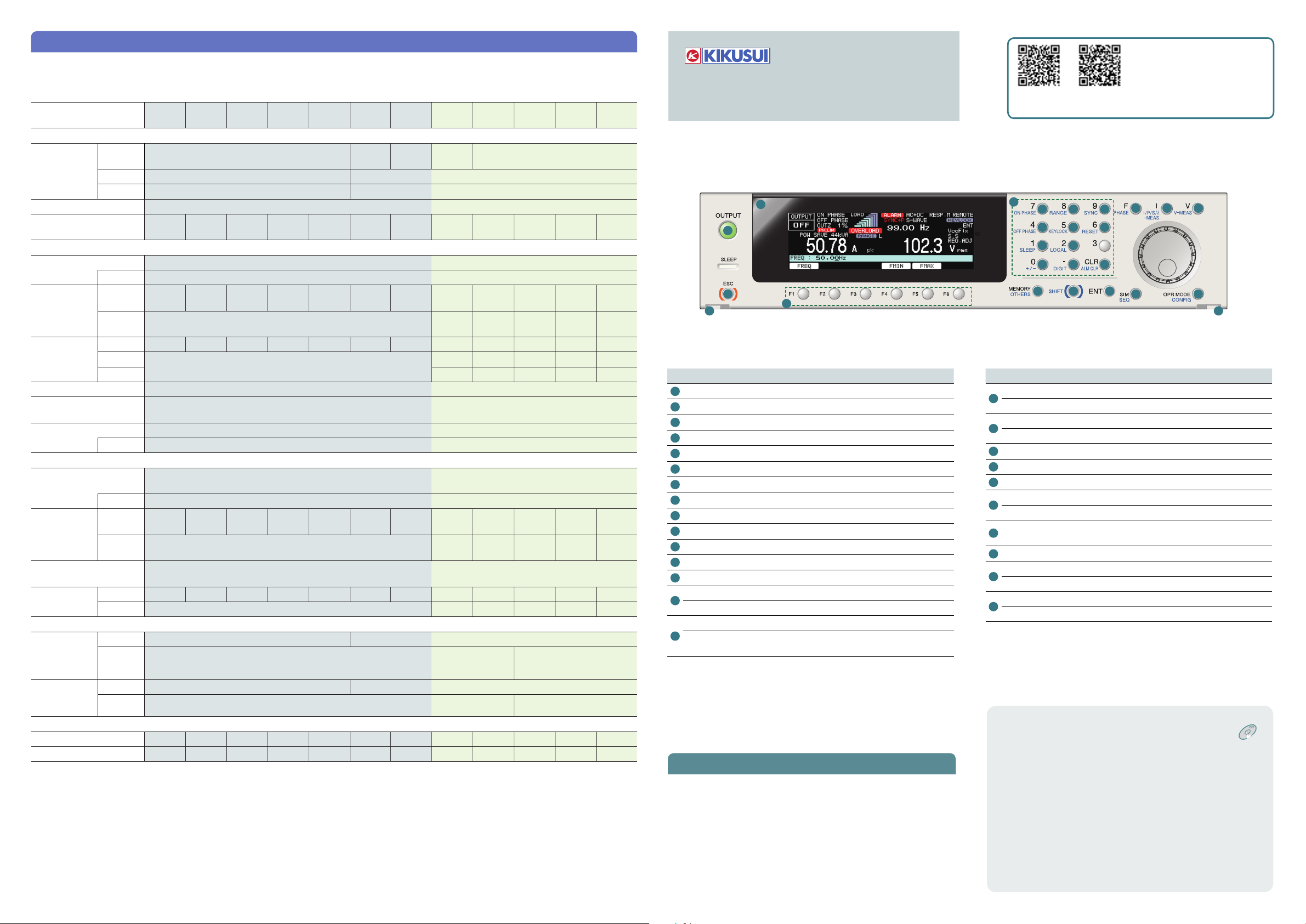
PCR-LE PCR-LE2
Quick Reference
2
1
18
19 19
Name Function
1
OUTPUT key Turn output on and off
2
Display Display the settings/ measured value
3
Numeric keypad Enter numeric values directly
4
ON PHASE key Set the output on phase
5
RANGE key Switch output voltage range
6
SYNC key Set the synchronization function
7
OFF PHASE key Set the output off phase
8
KEYLOCK key Lock and unlock the keys
9
RESET key Reset the product
10
SLEEP key Set the sleep mode
11
LOCAL key Switch between remote and local mode
12
+/- key Switch the polarity of the voltage
13
DIGIT key The cursor moves to the left
CLR key Clear the numeric keypad input
14
ALM CLR key Clear alarms
F key Set the frequency
15
PHASE key
Alarms/Trouble
When a protection function is activated, an alarm (ALM-xx) or a
trouble indication (TRBL-xx) is generated, and the output is turned
off.
Alarm: Press ALM CLR(SHIFT+CLR) to clear the alarm, and then fix
the problem that caused the alarm.
Trouble: To clear the trouble indication, turn the POWER switch off,
wait at least 5 seconds, and turn it back on. If the same trouble
persists, contact your Kikusui agent or distributor to request repairs.
20
Switch different displays during multiphase
operation (optional)
The newest version of the
operation manual can be
downloaded from Kikusui website.
http://www.kikusui.co.jp/en
PCR-LE
manual
3
4
7
10
12
21 22 23
Name Function
I key Configure the current settings
16
I/P/λ-MEAS key Switch the current/power measurement mode
V key Configure the voltage settings
17
V-MEAS key Switch the voltage measurement mode
18
ESC key Cancel operations
19
Detachment button Detach the control panel
20
Function key Correspond to the menus on display
MEMORY key Save/Load settings from memory
21
OHTERS key Configure advanced operation settings
22
SHIFT key
23
ENT key Apply settings
SIM key Configure power line abnormality simulations
24
SEQ key Configure sequence operations
OPR MODE key Configure the operation environment settings
25
CONFIG key Specify the configuration settings
The accompanying CD-ROM describes the following
information.
Two-phase output setting PCRLE optional
Voltage compensation function
Harmonic current analysis
function
Generating special waveforms
(waveform bank)
Setting the output impedance
Setting soft starts (the voltage
rise time)
Fixing the internal Vcc
Selecting the response
Controlling the Output Using
PCR-LE2
manual
15
5
8
11
13 14
6
9
16 17
24 25
Enable the functions that are indicated in the
bottom row to the left of each key
External Analog Signals
(Optional)
Remote control
Sequence tutorial
Options
Troubleshooting
Maintenance
Factory default settings
Alarms/ Trouble
Specifications
Table for power line abnormality
simulation settings
Table for sequence settings
To turn the output on
List of function keys
Single-phase output
Set the Output Mode.
1.
Press OPR MODE and then ACDC (F2) to
select the output mode.
Set the output voltage mode.
2.
Press RANGE(SHIFT+8) to select the
output voltage range.
You cannot set the mode if the output is
turned on.
Set the output voltage.
3.
To set the AC voltage, press V and then
ACVOLT(F1). To set the DC voltage, press
V and then DCVOLT(F2).
Set the frequency. (AC/ AC+DC
4.
mode only)
Press F and then FREQ(F1).
Turn the OUTPUT on.
5.
Press the OUTPUT key.
Single-phase, three-wire output or Three-phase output (PCR-LE optional)
Select the output method (PCR-LE2 only).
1.
Press OPR MODE and then WIRING (F5). If you select single-phase, three-wire output, the output
is generated from the OUTPUT 1P2W terminal block. If you select three-phase output, the output
is generated from the OUTPUT 3P4W (1P3W) terminal block.
Set the Output Mode.
2.
Press OPR MODE and then ACDC (F2) to select the output mode.
Set the output voltage range.
3.
Press RANGE(SHIFT+8) to select the output voltage range. You cannot set the range if the output
is turned on.
Set the output voltage.
4.
In AC+DC mode, the function key names are different. See “List of function keys.”
Single-phase, three-wire output
Set the AC voltage with phase voltages
To set all the phases at the same time, press V
and then PHAS VOLT (F1).
To set each phase separately, press U
VOLT (F1) or V VOLT (F2). To set the phase
difference, press UV PHASE (F4).
Set the DC voltage with phase voltages
Press V and then PHAS VOLT (F1). Then,
specify one-half the voltage that is required
for the line voltage. The V phase is set to
the same amplitude as the U phase but with
opposite polarity.
Set the output voltage with a line voltage
Press V and then LINE VOLT (F2). Then, set
the voltage. Use phase voltages to set the DC
voltage of AC+DC mode.
Set the frequency. (AC/ AC+DC mode only)
5.
Press F and then FREQ(F1).
Turn the OUTPUT on.
6.
Press the OUTPUT key.
Three-phase output
Set the AC voltage with phase voltages
To set all the phases at the same time, press V
and then PHAS VOLT (F1).
To set each phase separately, press U VOLT (F1),
V VOLT (F2), or W VOLT(F3).
To set the phase difference, press UV PHASE (F4)
or UW PHASE (F5).
Set the AC voltage with line voltages
Press V and then LINE VOLT(F2).
Set the DC voltage (AC+DC mode only)
To set all the phases at the same time, press V
and then DC PH VOLT(F3).
To set each phase separately, press U
DCVOLT(F1), V DCVOLT(F2), or W DCVOLT(F2).
Key Standard function
Key Standard function for the PCR-LE2,
option for the PCR-LE
Key Option
Some items may not be displayed depending on how
the product is configured.
V key
ACVOLT AC voltage
DCVOLT DC voltage
UV PHASE U-V phase difference
UW PHASE U-W phase difference
PHAS VOLT*1 Voltage of all the phases
U VOLT*1 Voltage of U phase
V VOLT*1 Voltage of V phase
W VOLT*1 Voltage of W phase
LINE VOLT*1 Line voltage
PROTECT OVP
VMAX Voltage upper limit
VMIN Voltage lower limit
*1. Use the following soft keys when AC+DC is selected.
Output overvoltage protection
UVP Output undervoltage
protection
Setting of AC voltage
AC PH VOLT Voltage of all the phases
U ACVOLT Voltage of U phase
V ACVOLT Voltage of V phase
W ACVOLT Voltage of W phase
AC LIN VOLT Line voltage
Setting of DC voltage
DC PH VOLT Voltage of all the phases
U DCVOLT Voltage of U phase
V DCVOLT Voltage of V phase
W DCVOLT Voltage of W phase
F key
FREQ Frequency
FMAX Frequency upper limit
FMIN Frequency lower limit
I key
ILIMIT Current limit
+IPKLIM Positive peak limit
-IPKLIM Negative peak limit
TRIP Action to perform when the limit is
exceeded
TRIP
TIM
OCP
TIM
Time that elapses after the limit is
exceeded until the output is turned off
Time that elapses after the
semiconductor protection function is
activated until an alarm is generated
V-MEAS (SHIFT+V) key
RMS Displays the rms voltage
PEAK Displays the peak voltage
AVE Displays the average voltage
LINE Switches between line voltage and
phase voltage
I/P/S/λ-MEAS (SHIFT+I) key
RMS Displays the rms current
PEAK Displays the peak current
AVE Displays the average current
P Displays the power
PKCLR Clears the peak current
S Displays the apparent power
λ
TOTAL P Displays the total power
TOTAL S Displays the apparent power
TOTAL λDisplays the total power factor
IPK TIM The hold time
Displays the power factor
MEMORY key
RCL No. Recalls settings from memory
STR No. Stores settings in memory
OTHER (SHIFT+MEMORY) key
RISETIM Soft start
WAVE
WB No.
EDIT
WB No. Number of the
SIN Sine wave
P. C Crest factor
OUT IMP Output impedance
FFT ALL All orders
ODD Odd-numbered orders
EVEN Even-numbered orders
AMPER
PCT
U Selects the U phase
V Selects the V phase
W Selects the W phase
VCC Internal Vcc, fixed or
COMPEN
RESP Response
PON OUTP Output status when the
FILE LOAD Recalls settings from a
SAVE
APERTUR Aperture time
EXT SIG SOUR Signal source (EX05-
POL Polarity
VPROG Signal source (EX06-
Number of the waveform
bank to execute
waveform bank to edit
Unit that is used to display
the harmonic components
automatic
Compensation function
power is turned on
USB memory device
Saves data to a USB
memory device
PCR-LE)
PCR-LE)
SLEEP (SHIFT+1) key
ON/ OFF Sleep function
EXEC Starts the sleep function instantly
OFF PHASE (SHIFT+4) key
Output off phase control
ON PHASE (SHIFT+7) key
Output on phase control
RANGE (SHIFT+8) key
Output voltage range
SYNC (SHIFT+9) key
ON/ OFF Synchronization function
DELAY Synchronization delay phase angle
CONFIG (SHIFT+ OPR MODE) key
COM
TRACE Error display
-I/F
TYPE RS
SIG.I/O TRIG.IN Trigger input
DISPLAY INTEN
MODEL ID
DATE TIM Date and time
SURGE S Voltage surge
EXT.
CONTROL OUTP ON Controlling the
OPT
STAT.OUT
BAUDRATE
232C
DATABITS
STOP BITS
FLOW
CTRL
GPIB ADDRESS
USB
LAN
DHCP LAN CONFIG
AUTO IP
MANUAL
IP
TRIG.OUT Trigger output
STAT.OUT Status output
SEQ RUN Sequence
ALMCLR Alarm clear
SHUTDOWN
Baud rate
Data length
Stop bits
Flow control
GPIB address
USB
display and
DHCP function
LAN CONFIG
display and
automatic
IP address
assignment
LAN CONFIG
display and
manual IP
address
assignment
polarity
polarity
polarity
Screen brightness
adjustment
Model information
display
suppression
Output On/ Off
execute/ stop
Shut down the
output
Selecting the
phase to monitor
PHASE (SHIFT+F) key
Switches the phase to display
OPR MODE key
ACDC Output voltage mode
POW SAV Power-saving function
2P*1 Output mode
WIRING*2 Output mode
*1. PCR-LE optional only
*2. PCR-LE2 only
SIM key
RUN Execute
STOP Stop
LOOP Number of repetitions
COND POL Voltage regulation polarity
T1 TYPE Voltage regulation starting
setting type
T5 TYPE
EDIT T1 Voltage regulation starting
T2 Slope time 1
T3 Voltage regulation time
T4 Slope time 2
T5 Return time or the number
T3 VOLT Regulated voltage
Return state hold setting type
time or phase
of return cycles
SEQ (SHIFT+SIM) key
RUN Executes
STOP Stops
PAUSE
CONTINUE Unpauses
LOOP Number of repetitions
COND
START STEP Starting step number
END STEP Ending step number
EDIT STEP Step number
FREQ
ACVOLT AC voltage
ACV V AC voltage of V phase
ACV W AC voltage of W phase
TIME Time
WB NO Waveform bank number
OUTPUT Output
DCV DC voltage
DCV V DC voltage of V phase
DCV W DC voltage of W phase
STAT.OUT Status output
TRIG.OUT Trigger output
TRIG.IN Trigger input (pause)
TYPE Step type
JUMP STEP Jump destination step
JUMP CNT
S.PHASE Starting phase angle
E.PHASE Ending phase angle
PHAS. CHG Phase change
OUT IMP. Output impedance
U PHA.OFFS
UV PHASE U-V phase difference
UW PHASE U-W phase difference
U PHASE
Pauses
Frequency
RAMP
Signal change
RAMP
Signal change
RAMP
Signal change
Number of jump repetitions
U phase offset
RAMP
Signal change
RAMP
Signal change
RAMP
Signal change
Clears the U phase offset
 Loading...