

Page 1
PART NO. Z1-006-120, IB027733
(1pc.) [Z1-005-040]
PCR6000LE2/PCR9000LE2 only
Dec. 2014
Setup Guide
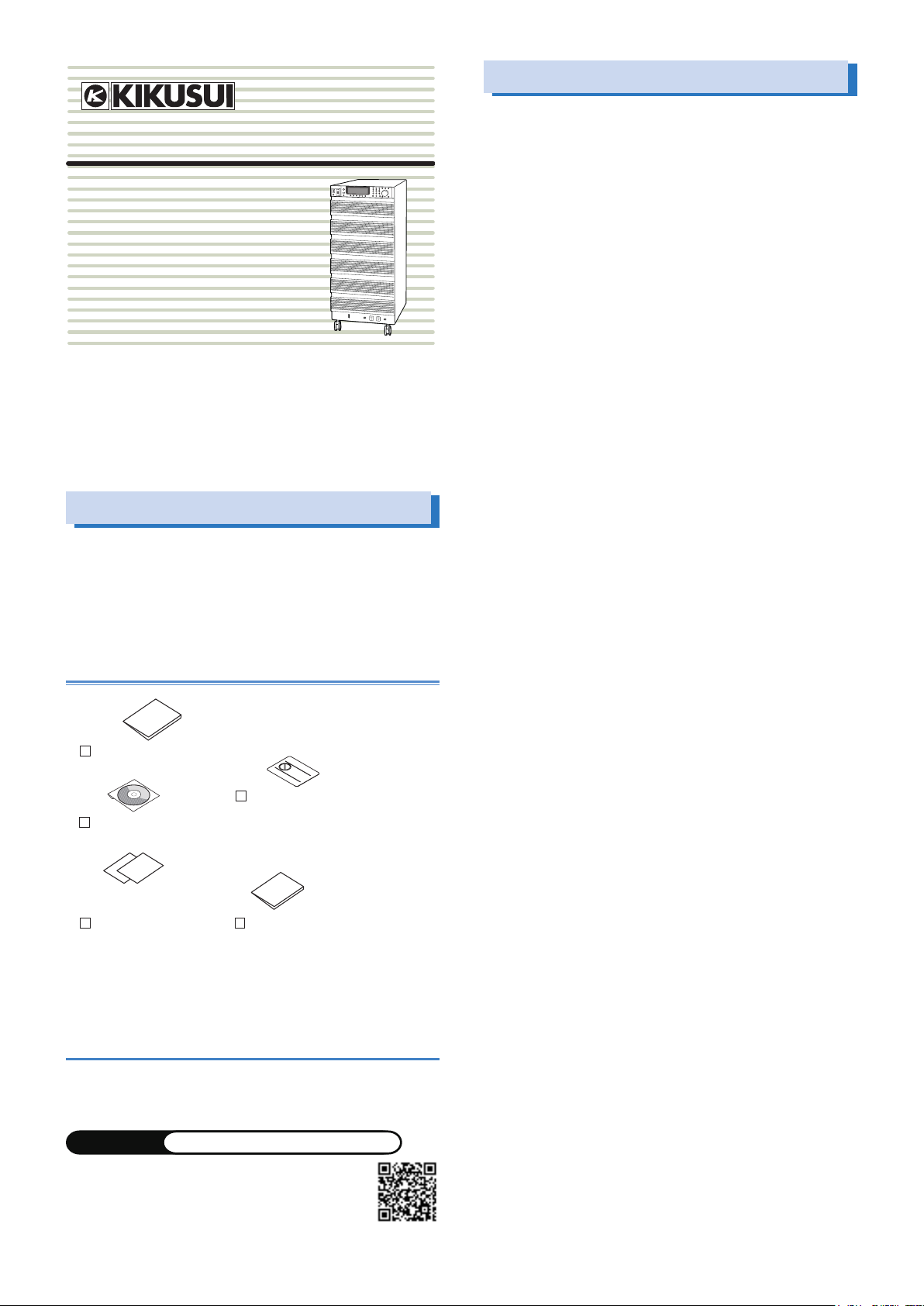
AC Power Supply PCR-LE2
seriess
PCR6000LE2
PCR9000LE2
PCR12000LE2
PCR18000LE2
PCR27000LE2
Thank you for purchasing the PCR-LE2 Series AC Power Supply.
The PCR-LE2 Series is a special version of the PCR-LE Series that
can produce highly pure AC signals through the combination of
its high-speed linear amplifier and arbitrary waveform synthesizer.
It features switchable single-phase, single-phase three-wire, and
three-phase outputs.
Checking the Package Contents
When you receive the product, check that all accessories are included and that the accessories have not been damaged during
transportation. If any of the accessories are damaged or missing,
contact your Kikusui agent or distributor. We recommend that you
save all packing materials, in case the product needs to be transported at a later date.
Accessory
If necessary, attach
Setup Guide (1pc.)
[Z1-006-120]
CD-ROM (1 pc.)
[SA-6060]
English: 1pc. [Z1-006-102]
Japanese: 1pc. [Z1-006-100]
Quick Reference Safety information
KIKUSUI ELECTRONICS CORP.
1-1-3, Higashiyamata, Tsuzuki-ku, Yokohama, 224-0023, Japan
TEL: +81-45-593-7570 Fax: +81-45-593-7571
WEBSITE
The newest version of the operation manual can be
downloaded from Download service of Kikusui website.
Printed in Japan © 2013
http://www.kikusui.co.jp/en
to the product.
Heavy object warning label
[A8-900-158]
PCR-LE2 manual
Features
The PCR-LE2 Series is equipped with the following features.
• Switchable between single-phase output, single-phase threewire output, and three-phase output
Three types of output are available on a single unit.
• Various power supply simulations
Power line abnormalities such as outages and voltage dips can
be simulated. This is a basic feature for power-supply-environment testing.
• Various measurements
The rms voltage and current, the peak voltage and current, the
active power, apparent power, and power factor of the output
can be measured. Harmonic analysis (up to the 40th harmonic)
can be performed on the output current.
• DC output
The PCR-LE2 Series can generate DC output (single-phase output or single-phase three-wire output only) and AC + DC output
(single-phase output only). This makes it possible to use the
PCR-LE2 Series in a wide variety of fields, including chemistry
and physics.
• Sequences
The output voltage, frequency, and waveform can be changed
over time. Power-supply-environment testing can be automated.
In addition to the AC output sequences, DC output (single-phase
output or single-phase three-wire output only) and AC + DC output (single-phase output only) sequences are also available. A
variety of standard tests can also be performed.
• Sensing and regulation adjustment
Even if the load device is at a remote location, the PCR-LE2 Series can stabilize the voltage across the load by correcting for
voltage drops.
There are two types of sensing: hard sensing (single-phase
output only) and soft sensing. The different types of sensing are
used depending on the load conditions and how you will use the
PCR-LE2 Series.
• Output current control
The output limit function can be used to limit the output current
(rms) to a fixed value to perform continuous operation. Continuity
tests on electrical equipment (such as switchboards, breakers,
and wiring devices) can be performed under stable conditions.
• Power management function (power saving function)
A sleep function, which turns the power units off to reduce power
consumption when output is not generated for the specified
length of time, and a power-saving function, which operates the
power units at the bare minimum settings as required by the supply load, are available.
• Memory function
Up to 99 entries of output frequency, voltage (AC or DC), and
waveform bank settings can be saved to the internal memory.
The contents of internal memory, panel settings, power line abnormality simulations, sequence data, and waveform bank data
can be saved to a USB memory device.
• External communications
The PCR-LE2 Series can be controlled remotely through its
RS232C interface. If an optional interface board is used, the
PCR-LE2 Series can be controlled remotely through USB, GPIB,
and LAN interfaces.
• External analog signal control (optional)
The EX05-PCR-LE/EX06-PCR-LE option enables you to control
the PCR-LE2 Series output using external analog signals.
PCR-LE2 series 1
Page 2
About the PCR-LE2 Documentation
These manuals are intended for users of the PCR-LE2 Series AC
Power Supply and their instructors.
Explanations are given under the presumption that the reader has
knowledge related to electric safety tests.
You can view the PDF file using Adobe Reader 6.0 or later.
The HTML can be viewed using the following browser.
Browser: Microsoft Internet Explorer 9.0 or later
Every effort has been made to ensure the accuracy of this manual.
However, if you have any questions or find any errors or omissions,
please contact your Kikusui agent or distributor.
If you find any misplaced or missing pages in this manual, it will be
replaced. If the manual gets lost or soiled, a new copy can be provided for a fee. To replace or purchase a manual, please contact
your Kikusui agent or distributor. At that time, inform your agent or
distributor of the “Part No.” written on the front cover of this manual.
After you have finished reading this manual, store it so that you can
use it for reference at any time.
Notations used in the PCR-LE2 manual
In the PCR-LE2 manual, the PCR-LE2 Series AC Power Supply is
also referred to as the PCR-LE2 Series and the PCR-LE2.
The term “PC” is used to refer generally to both personal computers and workstations.
The screen captures used in this manual may differ from the actual
screens that appear on the PCR-LE2. The screen captures are
merely examples.
The following markings are used in the explanations in the manual.
Contents of the Included CD-ROM
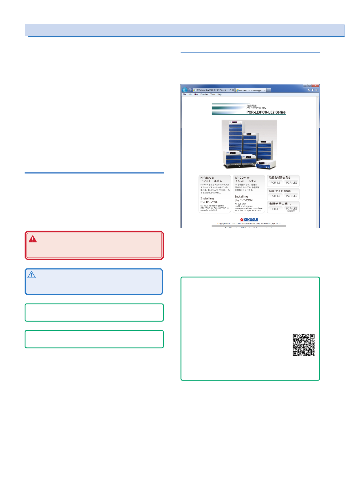
Put the included CD-ROM into the CD-ROM drive. In a few moments, a start window will appear. If the start window does not
appear, open the CD-ROM folder in Windows Explorer, and then
double-click index.html to display the start window.
WARNING
Indicates a potentially hazardous situation which, if ignored, could result in death or serious injury.
CAUTION
Indicates a potentially hazardous situation which, if ignored,
may result in damage to the product or other property.
- Note -
Indicates information that you should know.
- DESCRIPTION -
Explanation of terminology or operation principle.
(SHIFT+key name)
Indicates an operation that requires you to press a key indicated
in blue characters (the lower row of text to the left of the key)
while holding down the SHIFT key.
Accompanying CD-ROM contains following the items.
• KI-VISA x.x.x
• IVI-COM
• Operation Manual
Click the "See the Manual" to move to the Manual page.
- Tips -
How to view ePub les on a tablet
To view an ePub le on a tablet, an ePub reader (e.g., iBooks, Himawari Reader) must be installed in the tablet. You can download
ePub readers for free.
There are several ways to copy ePub les to your tablet, but we
recommend that you download them from the Kikusui Electronics
Corporation website.
1. Using a browser on your iPad, visit Kikusui Electronics Corporation website’s Operation Manual
Database (http://www.kikusui.co.jp/en/download/), and search for your PCR-LE2 series.
2. Tap the appropriate ePub le to download it.
When an ePub le is downloaded to your tablet, you can view it
even when the tablet is not connected to the Web.
2 PCR-LE2 series
Page 3

Documentation Structure
The PCR-LE2 Series manual comprises the following documentation.
User’s Manual -Basic-
• Front panel and Rear panel
• Panel Operation Basics
• Selecting the Output Mode
• Setting the Output Voltage/ Frequency
• Turning Output On and Off
• Displaying Measurement Values
How to switch the display of measured value.
• Setting Limits
Limits can be placed on the PCR-LE2 output voltage setting and
frequency setting. They prevent damage to the load caused by
mistaken operations and limit the current that flows through the
load. You can set limits in advance according to the load conditions.
• Using Protection Functions
The PCR-LE2 has the following protection functions.
Input voltage drop protection
Overheat protection (OHP)
Overload protection
Internal semiconductor protection (OCP)
Output undervoltage protection (UVP)
Output overvoltage protection (OVP)
• Using Memory
You can store data to the PCR-LE2’s internal memory and save
data to a USB memory device.
User’s Manual -Specications-
Specifications contains the electrical specifications and outline
drawings.
User’s Manual -Appendix-
• Glossary, Operation Characteristics, Output and load
• Peak hold current measurement
• Sequence tutorial
• Option
• Factory Default Settings
• Maintenance
• Troubleshooting
• Alarms and Trouble
• Error Message
Setup Guide (This guide)
This guide is intended for first-time users of the product. It gives an
overview of the product, connecting procedures, etc. Please read
through and understand this guide before operating the product.
Quick Reference
The quick reference briefly explains the panel description and the
basic operation of the product.
Safety information
This document contains general safety precautions for this product.
Keep them in mind and make sure to observe them.
Programming Sheet
• Table for Recording Power Line Abnormality Simulation Operation Settings (XLS)
• Table for Recording Sequence Operation Settings (XLS)
User's Manual -Advanced-
• Using the synchronization Function
The synchronization function synchronizes the frequency and
phase of the PCR-LE2 output voltage with a 50 Hz or 60 Hz input
power supply.
• Using the Voltage Compensation Function
The compensation function compensates for voltage drops in the
load cables when the load is connected to the PCR-LE2 over a
long distance.
• Using Power Line Abnormality Simulations
In AC mode, you can simulate power supply line errors by stop-
ping the PCR-LE2 output and decreasing and increasing the
voltage (to simulate voltage dips and pops).
• Using the Sequence Function
A sequence is a series of settings - values such as the output
voltage, frequency, and time - that are saved in advance and
are then recalled and automatically carried out in order at a later
time.
• Using the Harmonic Current Analysis Function
You can perform harmonic analysis of the output current.
• Generating Special Waveforms (Waveform bank)
You can generate peak-clipped sine waveforms.
• Setting the Output Impedance
The PCR-LE2 output impedance (output resistance) is approxi-
mately 0 Ω. Commercial power supplies have an impedance
(resistance) of several milliohms to several ohms. You can set
the PCR-LE2 output impedance. This enables you to simulate
the same environment as that which is provided by commercial
power supplies.
• Setting Soft Starts (The voltage rise time)
To prevent the output from being turned off (the alarm from be-
ing activated) and the voltage from dropping due to the load
device’s inrush current that exceeds the rated capacity of the
PCR-LE2, you can control the inrush current by having the output
voltage rise gradually when the output is turned on.
• Fixing the Internal Vcc
To minimize loss in the linear amplifier section, the PCR-LE2 au-
tomatically adjusts the linear amplifier supply voltage (Vcc) to a
level that is suitable for the output voltage. You can fix the Vcc
voltage of the PCR-LE2. This is useful when you want to prioritize
the output voltage response over the product’s efficiency.
• Selecting the Response
The PCR-LE2 uses a high-speed amplifier. Depending on the
load circuits (especially in the case of capacitive loads) and the
wiring conditions, the output may become unstable may oscillate. You can set the response speed of the internal amplifier
according to the load conditions and how you will use the PCRLE2.
• Using the Power Management Functions
The PCR-LE2 has the following two power management func-
tions: a sleep function and a power-saving function
• External analog signal control (optional)
You can use the optional analog signal interface board to control
the product with external analog signals.
Communication Interface Manual
This manual contains details about remote control.
Interface manual is written for readers with sufficient basic knowledge of how to control instruments using a personal computer.
PCR-LE2 series 3
Page 4
PCR-LE2 Series models
Three-phase output Single-phase three-wire output
1group
power unit
V
Stopper
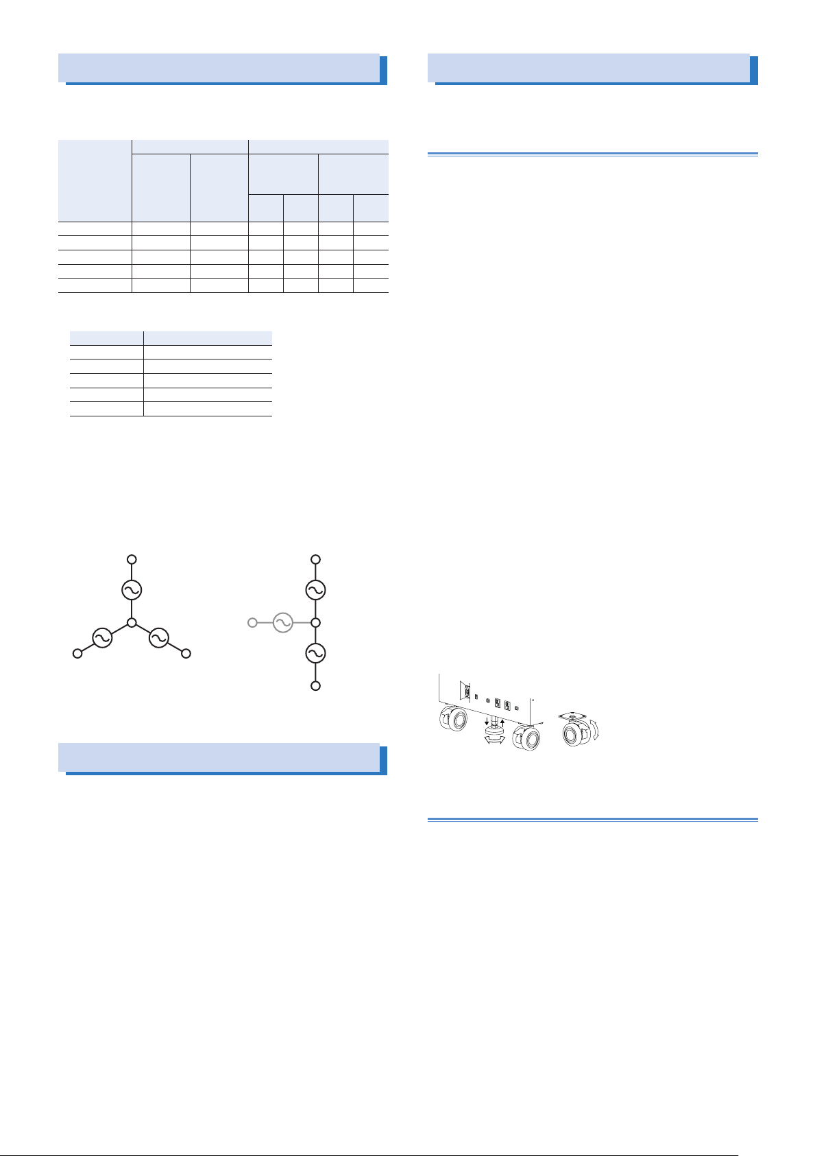
The PCR-LE2 Series generates single-phase output. The following
models are available
Model Rated output capacity Maximum output current
Singlephase,
Three-phse
PCR6000LE2 6 kVA 4 kVA 60 A 30 A 20 A 10 A
PCR9000LE2 9 kVA 6 kVA 90 A 45 A 30 A 15 A
PCR12000LE2 12 kVA 8 kVA 120 A 60 A 40 A 20 A
PCR18000LE2 18 kVA 12 kVA 180 A 90 A 60 A 30 A
PCR27000LE2 27 kVA 18 kVA 270 A 135 A 90 A 45 A
This product consists of three power unit groups.
Model Output capacity per group
PCR6000LE2 2 kVA
PCR9000LE2 3 kVA
PCR12000LE2 4 kVA
PCR18000LE2 6 kVA
PCR27000LE2 9 kVA
During single-phase output, all groups are used.
During single-phase three-wire output or three-phase output, each
phase (U, V and W) is assigned to a separate group.
During single-phase three-wire output, the phase W group is not
used. During three-phase output, all groups are used.
U U
1group
power unit
V
1group
power unit
Singlephase
three-wire
W
Single-phase Single-phase
100 V
output
1group
nonoperating
power unit
W
200 V
output
three-wire,
Three-phse
100 V
output
1group
power unit
1group
power unit
200 V
output
Moving the product
Precautions when moving the PCR6000LE2/
PCR9000LE2
Note the following points when moving the product to the installation location or when transporting the product.
●Raise the stopper.
Moving the product with the stopper lowered may cause injuries
due to the product falling over.
●Unlock the casters.
●Do not move the product by yourself.
Be sure to have two or more people move the product. Exercise
special care when carrying the product over a slope or across
steps.
Hold the product from underneath.
Check the product’s weight before you transport it. The weight is
displayed in the bottom of the rear panel.
If you are using a forklift, be sure to slide the forks under the bottom of the product, check that the product is stable, and then
raise the product.
If you are using a band or similar item to raise the product with a
crane, be sure to slide the band under the bottom of the product,
check that the product is stable, and then raise the product.
●When you move the product, do not tip the product on its side or
turn it upside down.
Locking the casters and using the stopper
This product has casters on its bottom side, so it is easy to move
the product. To ensure that the product is not moved accidentally
while it is being operated, use the stopper to fix the product in
place, and lock the casters.
Looking down at the stopper from above, turning the stopper to the
left (counterclockwise) raises the stopper, and turning the stopper
to the right (clockwise) lowers the stopper.
Lowering the lock lever on a caster locks the caster, and raising the
lock lever unlocks the caster.
Precautions Concerning Installation
When installing this product, be sure to observe the precautions provided in “Precautions Concerning Installation Location” in the Safety
information manual. Items specific to this product are given below.
●When you install the product, be sure to observe the temperature
and humidity ranges indicated below.
Operating temperature range: 0 °C to 50 °C (32 °F to 122 °F)
Operating humidity range: 20 %rh to 80 %rh (no condensation)
●When you store the product, be sure to observe the temperature
and humidity ranges indicated below.
Storage temperature range: -10 °C to 60 °C (14 °F to 140 °F)
Storage humidity range: 90 %rh or less (no condensation)
●Allow at least 20 cm of space between the air inlet/outlet and the
wall (or obstacles).
●Fix PCR6000LE2s and PCR9000LE2s to the floor using L-shaped
or other similar brackets.
Base Hold Angles (OP03-KRC) are available as options.
Down Up
Free
Lock
Precautions when moving the PCR12000LE2/
PCR18000LE2/ PCR27000LE2
The PCR12000LE2/ PCR18000LE2/ PCR27000LE2 cannot be
moved after it has been installed. If you need to move it, contact
your Kikusui agent or distributor.
4 PCR-LE2 series
Page 5
Handling the Terminal Block Tray (PCR6000LE2/ PCR9000LE2)
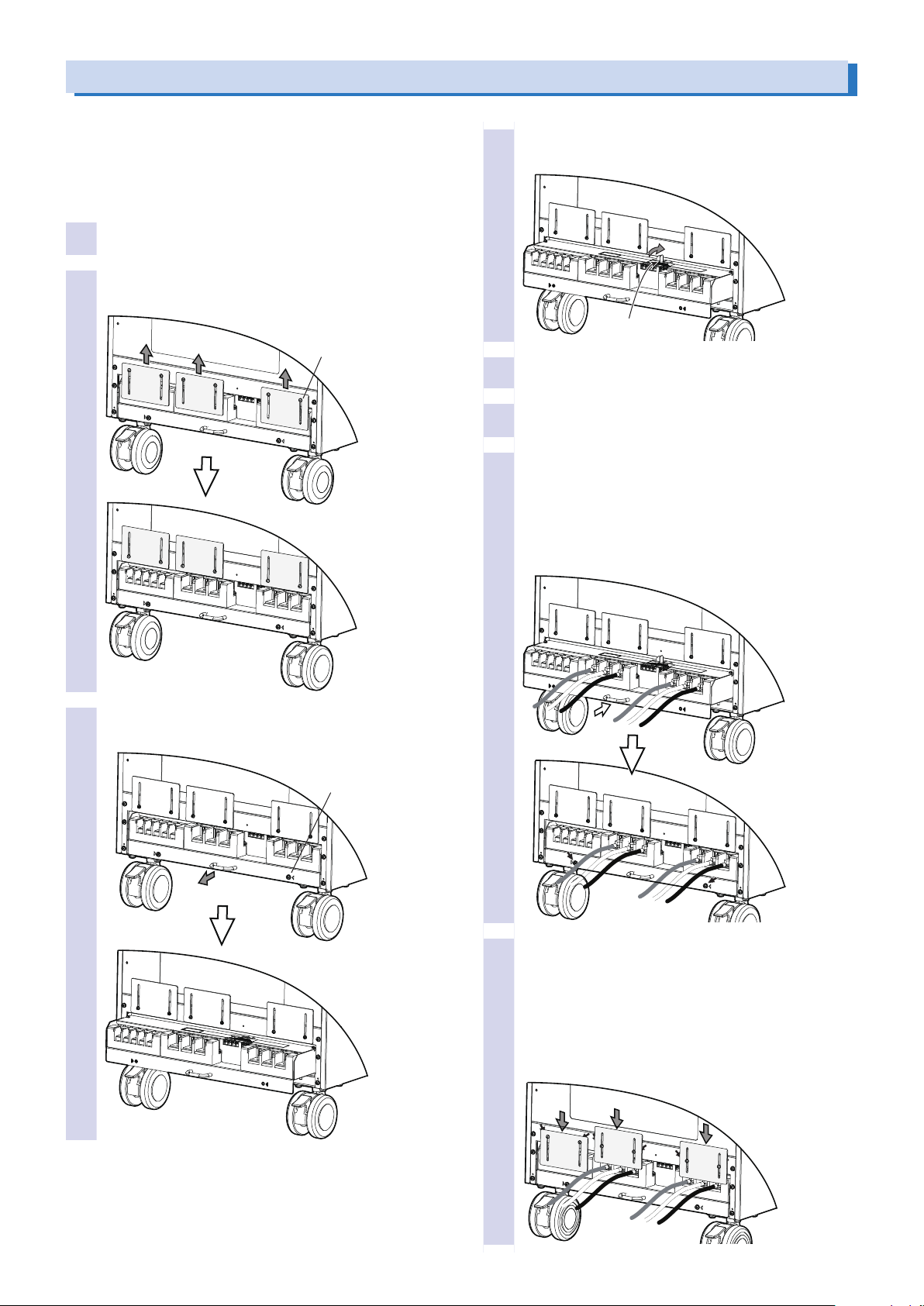
The PCR-LE2 Series AC INPUT, OUTPUT terminal block, SENSING
terminal block, and J1 to J4 connectors are designed so that they
can only be wired after you first pull out the terminal block tray.
The terminal box covers ensure that you don’t touch the unwired
terminals. Use a Phillips-head screwdriver to insert and remove the
screws.
Check that the POWER switch is turned off.
1
Loosen the six terminal box cover screws, and then
2
slide the three covers up.
M3 x 6
Pull out the stopper to lock the terminal block tray
4
in place.
Stopper
Connect the wires and cables to the terminal block
5
and connectors as necessary.
Return the stopper to its previous position.
6
Return the terminal block tray to its previous posi-
7
tion, and then attach the two screws that you removed in step 3
If you do not insert the terminal block tray all the way into
its storage compartment, an electric current will not flow
through the PCR-LE2 even if the POWER switch is turned
on.
Remove the two terminal block tray screws, and
3
then pull the tray out.
M4 x 2
Slide the two terminal box covers down until they
8
are touching the wires, and then use the four
screws to x the terminal box covers in place. Slide
the terminal box cover all the way down if none of
their terminals have wires connected to them, and
use the two screws to x the covers in place.
The figure below is an example for when the OUTPUT terminal blocks for single-phase output are in use.
PCR-LE2 series 5
Page 6
(PCR6000LE2 only)
Connecting the power cord
This product conforms to IEC Overvoltage Category II (energyconsuming equipment that is supplied from a fixed installation).
WARNING
Risk of electric shock.
• This product conforms to IEC Safety Class I (equipment
that has a protective conductor terminal). Be sure to
earth ground the product to prevent electric shock.
• Connect the protective conductor terminal to earth
ground.
• Turn off the circuit breaker of the switchboard before
you connect the power cord.
• Do not use the product with the terminal box covers
removed.
Risk of electric shock or re.
• For the connected switchboard, select a breaker that
has a cut-off current that can handle the maximum input current of the product
• Have a qualified engineer connect the power cord to
the switchboard.
CAUTION
If the voltage distortion of the AC power line is large, the
product may malfunction. The PCR-LE2 Series cannot be
connected to a generator or a similar device.
Inside the product, protective circuits such as input fuses are
connected to match the polarity of the input terminal. Be sure
to match the colors of the wires and the input terminals to
connect the wires correctly.
Single-phase, 200 V input (PCR6000LE2 only):
L, N, and
Three-phase, 200 V input: R, S, T, and
Three-phase, 400 V input: R, S, T, N, and
(GND)
(GND)
(GND)
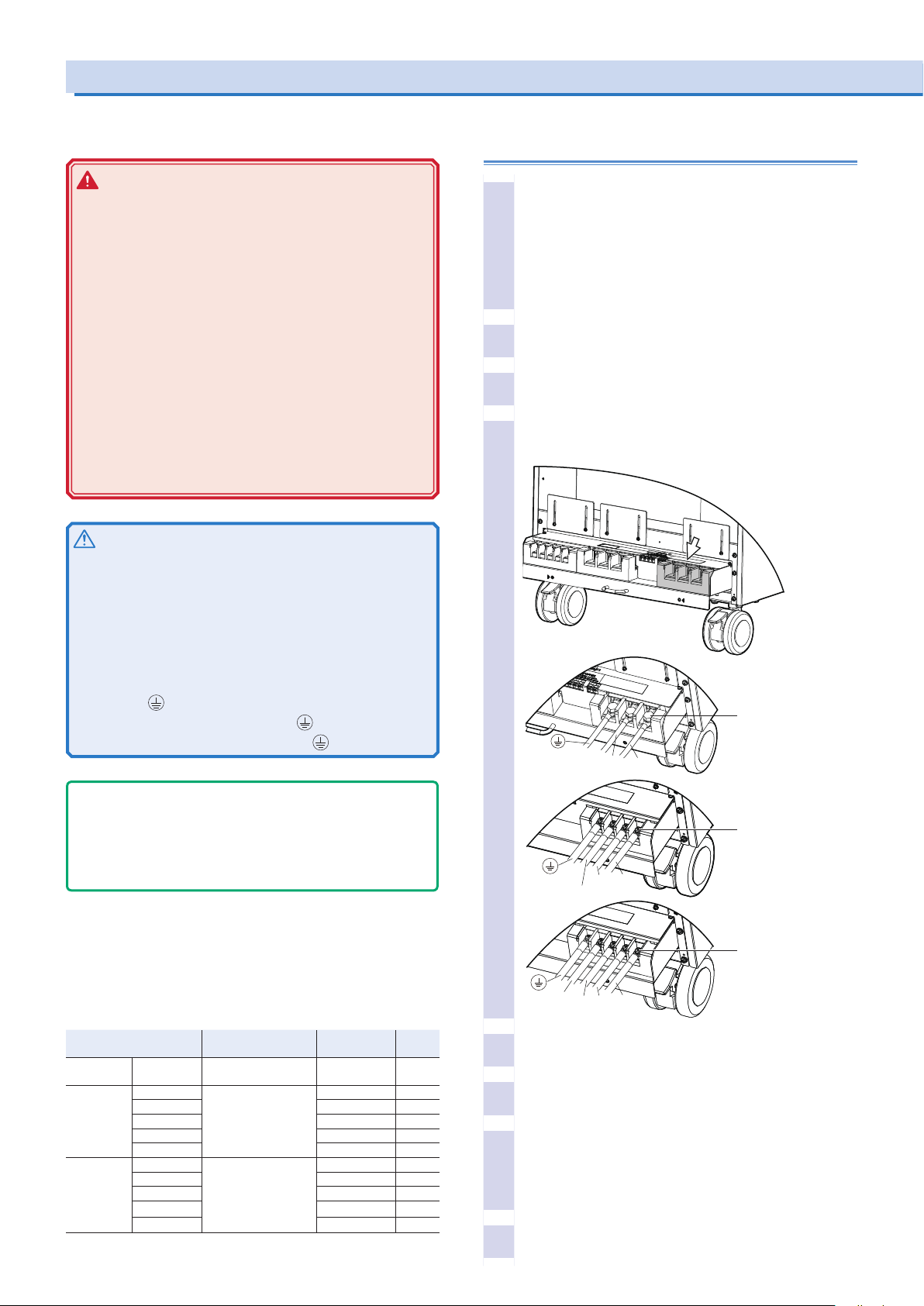
Connecting power cords to the PCR6000LE2
or PCR9000LE2
Check that the AC power line meets the nominal in-
1
put rating of the product.
The product can receive a nominal power supply voltage:
Single-phase, 200 V input (PCR6000LE2 only):
200 Vac to 240 Vac
Three-phase 200 V input: 200 Vac to 240 Vac (Line Voltage)
Three-phase, 400 V input: 220 Vac to 240 Vac (Phase Voltage)
Frequency: 50 Hz or 60 Hz.
Check that the POWER switch is turned off.
2
Pull out the terminal block tray.
3
Securely connect the power codes to corresponding
4
terminals of AC INPUT terminal block.
Single-phase
200 V input
N
L
M8
- Note -
The POWER switch can be used to disconnect the product from
the AC power line in an emergency (On the PCR27000LE2, the
MASTER POWER switch and the two SLAVE POWER switches
must be turned off.). Provide enough space around the POWER
switch to ensure that it can be turned off at any time.
A power cord is not supplied with the PCR-LE2 Series.
Input power cords are available as options. When you are wiring
the switchboard, attach crimping terminals that match the screws
of the switchboard that has been connected by a qualified engineer.
If you will not use one of the optional input power cords, prepare a
power cord that meets the following specifications.
Single-phase,
200 V input
Three-phase,
200 V input
Three-phase,
400 V input
PCR6000LE2 Three single-core
PCR6000LE2 Four single-core cables 8 mm2 or more M5
PCR9000LE2 14 mm2 or more M5
PCR12000LE2 22 mm2 or more M8
PCR18000LE2 38 mm2 or more M8
PCR27000LE2 60 mm2 or more M8
PCR6000LE2 Five single-core cables 5.5 mm2 or more M5
PCR9000LE2 5.5 mm2 or more M5
PCR12000LE2 8 mm2 or more M8
PCR18000LE2 14 mm2 or more M8
PCR27000LE2 38 mm2 or more M8
Cable Nominal cross-
sectional area
14 mm2 or more M8
cables
Input
terminal
Three-phase
200 V input
M5
S R
T
Three-phase
400 V input
M5
N
S R
T
Turn off the switchboard’s breaker.
5
Securely connect the power codes to corresponding
6
terminals of switchboard's breaker.
Return the terminal block tray to its previous position.
7
If you do not insert the terminal block tray all the way into
its storage compartment, an electric current will not flow
through the PCR-LE2 Series even if the POWER switch is
turned on.
Turn on the switchboard’s breaker.
8
6 PCR-LE2 series
Page 7
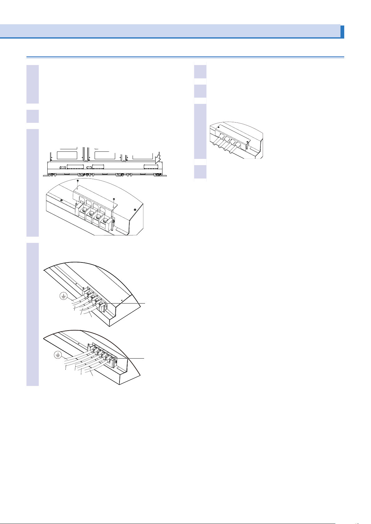
Connecting power cords to the PCR12000LE2, PCR18000LE2, or PCR27000LE2
M8
Check that the AC power line meets the nominal in-
1
put rating of the product.
The product can receive a nominal power supply voltage:
Three-phase 200 V input: 200 Vac to 240 Vac (Line Voltage)
Three-phase, 400 V input: 220 Vac to 240 Vac (Phase Voltage)
Frequency: 50 Hz or 60 Hz.
Check that the POWER switch is turned off.
2
Unfasten the screws (two locations) of the AC INPUT
3
terminal block cover, and remove the cover.
Connect the power cords according to the indica-
4
tions on the terminal block.
Turn off the switchboard’s breaker.
5
Securely connect the power codes to corresponding
6
terminals of switchboard's breaker.
Fasten the cover that you removed in step 3 with the
7
screws (two locations).
Turn on the switchboard’s breaker.
8
Three-phase
200 V input
T
S
R
Three-phase
400 V input
M8
N
T
S
R
PCR-LE2 series 7
Page 8
POWER
10A MAX 10A MAX
CIRCUIT
BREAKER
CIRCUIT
BREAKER
OUTPUT
DO NOT USE
OVER AC250V
MASTER POWER
SLAVE POWER
SLAVE POWER
AC1-150V/AC2-300V MAX27kVA
DC1.4-212V/DC2.8-424V MAX18.9kVA
DC・1-999.9Hz
AC POWER SUPPLY
PCR27000L E
2
switch
switch
switch
ACLOAD
Turning the Power On
Turning the POWER switch on
Turn the power on without the load connected.
If the POWER switch is turned on for the first time after purchasing the PCR-LE2 Series, the PCR-LE2 Series starts up using factory default settings. For all other cases, the PCR-LE2 starts up using the settings that were in use the last time that the POWER switch was turned off.
You can set the output on/off state at power on. For details, see “User’s Manual -Basic-“ on the accompanying CD-ROM.
If “ALARM” or an error number is displayed, see “Alarms and Trouble” on the accompanying CD-ROM.
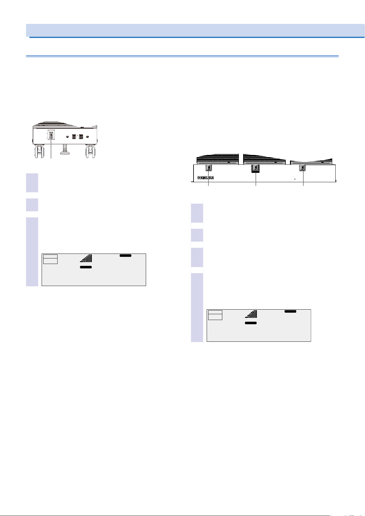
Turning on the POWER switch on the PCR6000LE2
or PCR9000LE2.
POWER switch
Check that nothing is connected to the OUTPUT ter-
1
minal block on the rear panel and the outlets on the
front panel.
Check that the power cord is connected correctly.
2
Flip the POWER switch to the ( | ) side to turn the
3
PCR-LE2 Series on.
The firmware version is displayed for a few seconds. If no
errors are detected, the home position (the basic screen)
appears.
RESP.M
99.00
ACLOAD
Hz
0.0
V
OUTPUT
OFF
0.00
RANGE L
pk rms
A
Turning on the POWER switch on the
PCR12000LE2, PCR18000LE2, or 27000LE2
The PCR-LE2 series has a MASTER POWER switch and SLAVE
POWER switches. You can turn off a SLAVE POWER switch to disconnect the product from the AC power line in an emergency. Normally, leave the SLAVE POWER switches turned on at all times, and
use the MASTER POWER switch to turn on the product.
SLAVE POWER
Check that nothing is connected to the OUTPUT ter-
1
minal block on the rear panel and the outlets on the
MASTER POWER
front panel.
Check that the power cord is connected correctly.
2
Check that the two SLAVE POWER switches are
3
ipped to the ( | ) side.
If not, flip them to the ( | ) side.
Flip the MASTER POWER switch to the ( | ) side to
4
turn the PCR-LE2 Series on.
The firmware version is displayed for a few seconds. If no
errors are detected, the home position (the basic screen)
appears.
OUTPUT
OFF
0.00
A
99.00
RANGE L
pk rms
Hz
0.0
RESP.M
SLAVE POWER
V
8 PCR-LE2 series
Page 9

Turning the POWER switch off
• PCR6000LE2, PCR9000LE2
Flip the POWER switch to the ( ) side to turn the PCR-LE2 Series off.
• PCR12000LE2, PCR18000LE2, PCR27000LE2
Flip the MASTER POWER switch to the ( ) side to turn the
PCR-LE2 Series off.
When the POWER switch is turned on, all items except for the following items take on the values that were in use the last time that
the POWER switch was turned off.
Waveform bank contents from number 24 to number 63
Output on/off state
If the POWER switch is turned off immediately after the settings
have been changed, the last settings may not be stored.
CAUTION
Risk of malfunction. After turning the POWER switch off, wait
at least 5 seconds before turning it back on.
Turning off the POWER switch in an emergency
• PCR6000LE2, PCR9000LE2
Turning off the POWER switch disconnects the product from the
AC power line.
• PCR12000LE2, PCR18000LE2, PCR27000LE2
Turning off the MASTER POWER switch and the two SLAVE
POWER switches disconnects the product from the AC power
line.
Provide enough space around the POWER switches to ensure that
them can be turned off at any time.
PCR-LE2 series 9
Page 10
Connecting the Load
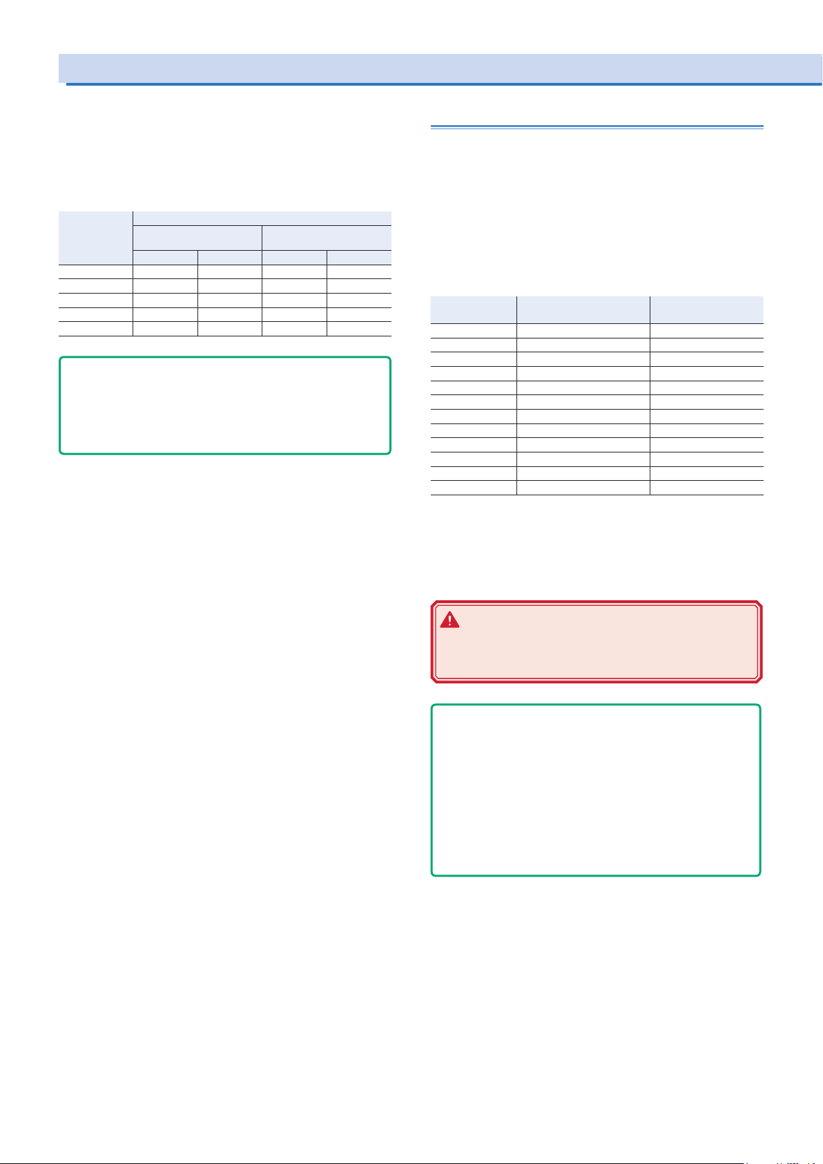
The maximum current that the PCR-LE2 Series can generate varies
depending on the model. It also varies depending on the PCR-LE2
Series’ voltage mode, load type, and status. Ensure that the output
power capacity is sufficient for the load capacity. The maximum
output currents (in AC mode—AC rms, with an output voltage of 1
V to 100 V or 2 V to 200 V, and with a load power factor of 0.8 to 1)
for the different models are shown in the table.
Model Maximum output current
Single-phase output Single-phase three-wire output
Three-phase output
L range H range L range H range
PCR6000LE2 60 A 30 A 20 A 10 A
PCR9000LE2 90 A 45 A 30 A 15 A
PCR12000LE2 120 A 60 A 40 A 20 A
PCR18000LE2 180 A 90 A 60 A 30 A
PCR27000LE2 270 A 135 A 90 A 45 A
- DESCRIPTION -
When the POWER switch is on, even if the output is off, a dan-
gerous voltage exists between the output terminal (L/N or U/V/W/
N) and the chassis (G-ground). To eliminate the voltage between
the output terminal and the chassis, connect N and G of the OUT-
PUT terminal block.
Connecting to the OUTPUT terminal block
We recommend that you run the load wires alongside each other
and tie them together at several points with cable ties. Connect between the output terminal and load with the shortest wires possible.
Preparing wires
Use noncombustible wires that have diameters that correspond to
the output current to connect to the load.
Requirements of single-core wires that are used to connect to
the load
Nominal crosssectional area[mm2]
0.9 18 (0.82) 17
1.25 16 (1.31) 19
2 14 (2.08) 27
3.5 12 (3.31) 37
5.5 10 (5.26) 49
8 8 (8.37) 61
14 6 (13.3) 88
22 4 (21.15) 115
38 1 (42.41) 162
60 2/0 (67.42) 217
80 3/0 (85.03) 257
100 4/0 (107.2) 298
* Excerpt from Japanese laws related to electrical equipment.
AWG (reference cross-
sectional area; mm2)
Allowable current*
(A; at Ta = 30 °C, 86 °F)
The values vary depending on conditions such as the wire covering
(insulator), the wire material (allowable temperature), and whether
there are multiple cores in the cable. For cables other than those
specified in this table, consult with a qualified engineer.
WARNING
Risk of electric shock. Before you connect cables to
the OUTPUT terminal block, be sure to turn the POWER
switch off, and then turn off the switchboard.
- Note -
The L and N terminals of the OUTPUT terminal block are isolated
from the input power supply. The polarity does not constitute a
problem in terms of safety. The polarity matters in synchro mode
(in which the product is synchronized with the input power supply) and DC mode, so check the polarity of the load before you
connect it to the product. You can use either L or N to ground the
product.
In DC mode and AC+DC mode, N is the reference. When N has
a positive polarity, L is positive electric potential. When N has a
negative polarity, L is negative electric potential.
Screw diameter of OUTPUT terminals
• PCR6000LE2, PCR9000LE2
Single-phase output: M8
Singlle-phase three-wire output, Three-phse output: M5
• PCR12000LE2, PCR18000LE2, PCR27000LE2
M8
10 PCR-LE2 series
Page 11
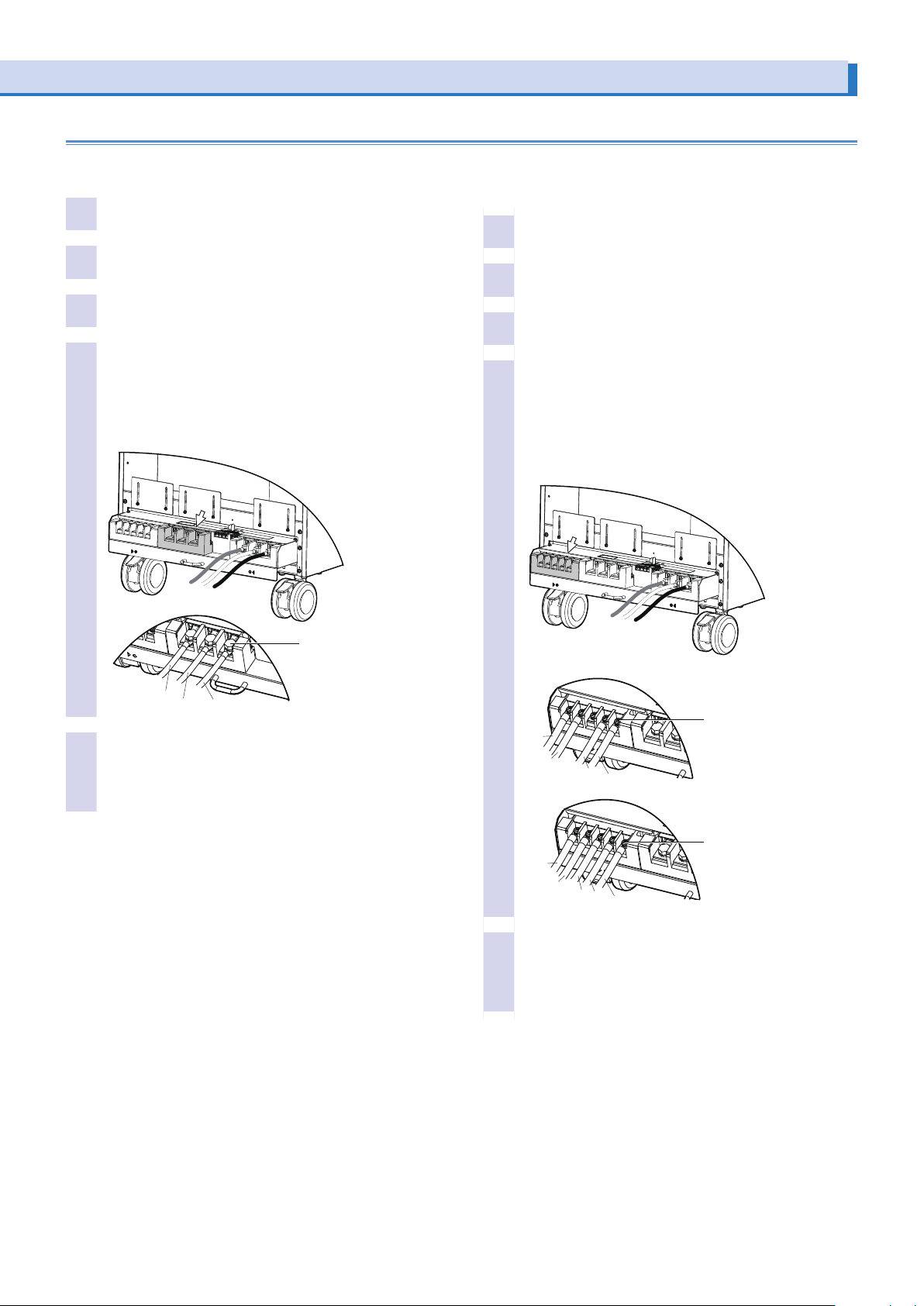
Connecting cables to the PCR6000LE2 or PCR9000LE2
Single-phase output
Check that the POWER switch is turned off.
1
Check that the breaker of the switchboard is off.
2
Pull out the terminal block tray.
3
Securely connect the load cables to the OUTPUT
4
1P2W terminal block.
If the load has a ground (GND) terminal, be sure to connect it
to the G terminal of the PCR-LE2 Series OUTPUT 1P2W terminal block. Be sure to use a wire whose diameter is greater than
or equal to the diameter of the wires used to connect the load.
Single-phase three-wire output or three-phase out-
put
Check that the POWER switch is turned off.
1
Check that the breaker of the switchboard is off.
2
Pull out the terminal block tray.
3
Securely connect the load cables to the OUTPUT
4
3P4W(1P3W) terminal block.
If the load has a ground (GND) terminal, be sure to connect it
to the G terminal of the PCR-LE2 Series OUTPUT 3P4W(1P3W)
terminal block. Be sure to use a wire whose diameter is greater
than or equal to the diameter of the wires used to connect the
load.
M8
G
N
L
Return the terminal block tray to its previous position.
5
If you do not insert the terminal block tray all the way into
its storage compartment, an electric current will not flow
through the PCR-LE2 Series even if the POWER switch is
turned on.
OUTPUT 1P2W terminal block
OUTPUT 3P4W(1P3W) terminal block
M5
G
N
V
U
G
N
W
V
U
Return the terminal block tray to its previous position.
5
If you do not insert the terminal block tray all the way into
its storage compartment, an electric current will not flow
through the PCR-LE2 Series even if the POWER switch is
turned on.
Single-phase,
three-wire output
M5
Three-phase
output
PCR-LE2 series 11
Page 12
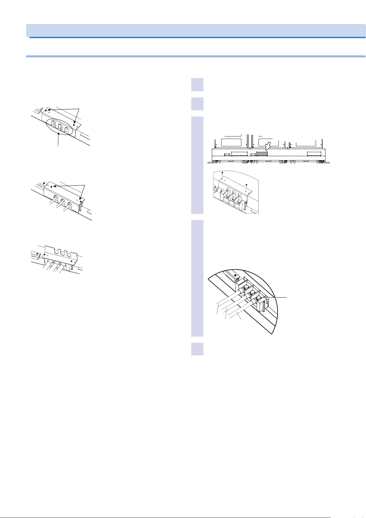
the output terminals are not exposed
Connecting the Load (Cont.)
Connecting wires to the PCR12000LE2, PCR18000LE2, or PCR27000LE2
Handling the output terminal cover
When shipped from the factory, the terminal cover is attached using
the left holes so that the OUTPUT terminals are not exposed.
If you are not using the OUTPUT terminal block, attach the terminal
cover as figure below.
Use the left holes to attach
the terminal cover.
When the terminal cover is attached using the left holes,
When the load cable you use is 38 mm2 (AWG1) or more, use the
right holes to attach the terminal cover.
Use the right holes to attach
the terminal cover.
Single-phase output
Check that the POWER switch is turned off.
1
Check that the breaker of the switchboard is off.
2
Unfasten the screws (two locations) of the OUTPUT
3
1P2W terminal block cover, and remove the cover.
OUTPUT 1P2W terminal block
When the load cable you use is 60 mm2 (AWG0/2) or less, flip the
terminal cover upside down and attach it.
Securely connect the load cables to the OUTPUT
4
1P2W terminal block.
If the load has a ground (GND) terminal, be sure to connect
it to the G terminal of the PCR27000LE2 OUTPUT 1P2W
terminal block. Be sure to use a wire whose diameter is
greater than or equal to the diameter of the wires used to
connect the load.
M8
G
N
Fasten the cover that you removed in step 3 with the
5
screws (two locations).
L
12 PCR-LE2 series
Page 13
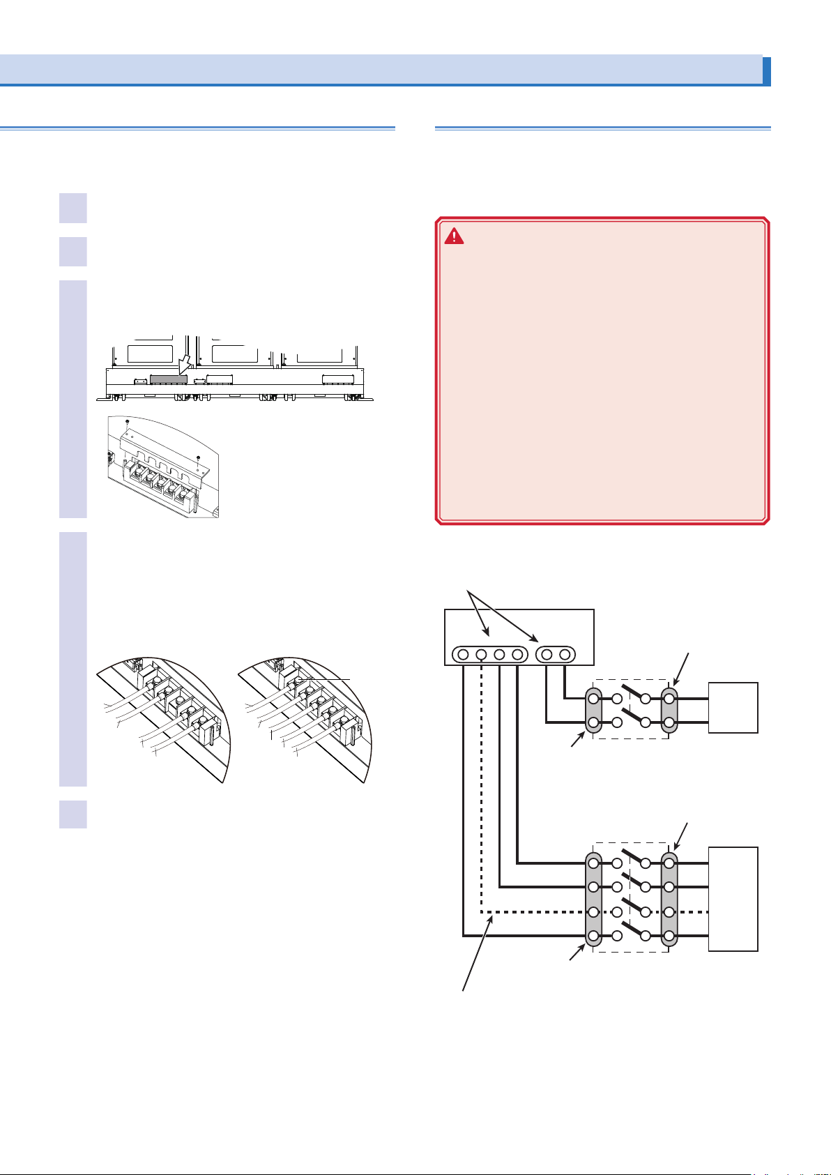
G
When the load is located at a remote location
Before you connect the cables, be sure to turn the POWER
Terminals on the load side
Turn the switch off, and then connect the load.
Single-phase three-wire output or three-phase out-
put
Check that the POWER switch is turned off.
1
Check that the breaker of the switchboard is off.
2
Unfasten the screws (two locations) of the OUTPUT
3
3P4W(1P3W) terminal block cover, and remove the
cover.
OUTPUT 3P4W(1P3W)
terminal block
Securely connect the load cables to the OUTPUT
4
3P4W(1P3W) terminal block.
If the load has a ground (GND) terminal, be sure to connect it to the G terminal of the PCR27000LE2 OUTPUT
3P4W(1P3W) terminal block. Be sure to use a wire whose
diameter is greater than or equal to the diameter of the
wires used to connect the load.
Three-phase outputSingle-phase three-wire output
G
5
N
V
U
Fasten the cover that you removed in step 3 with the
screws (two locations).
N
W
V
Remote control can be used to turn the output off, but it cannot be
used to turn the POWER switch off. If you want to connect the PCRLE2 Series to a load that is located at a remote location, install a
switch between the OUTPUT terminal block and the load to prevent
electric shock. Then, turn that switch off.
WARNING
Risk of electric shock.
• Before you install the switch between the OUTPUT terminal block and the load, be sure to turn the POWER
switch off and turn off the breaker of the switchboard.
• The current rating of the switch must be greater than
or equal to the maximum current of the PCR-LE2 Series.
• For the switch circuit, use a multi-pole switch that can
cut off all lines simultaneously (two poles for singlephase output, three poles for single-phase threephase output, and four poles for three-phase output).
• Be sure to turn the switch off before connecting the
load to the terminal at the load end of the switch.
• Do not touch the switch terminals when the POWER
switch is on. Before you connect cables to the OUTPUT terminal block, be sure to turn the POWER switch
off, and then turn off the switchboard.
switch off and turn off the breaker of the switchboard.
OUTPUT terminal block
PCR-LE2
N LN W V U
M8
U
Terminals on the OUTPUT terminal block side
Risk of electric shock. Do not touch the
terminals.
Terminals on the load side
Turn the switch off, and
then connect the load.
Switch
L
LOAD
N
Switch
U
V
LOAD
W
N
Terminals on the OUTPUT terminal block side
Not used during single-phase three-wire output.
PCR-LE2 series 13
Risk of electric shock. Do not touch the terminals.
Page 14
Connecting to the front-panel outlets
(PCR6000LE2/ PCR9000LE2 only)
The PCR-LE2 Series can generate power from the OUTPUT terminal block on the rear panel and the outlets on the front panel.
The outlets on the front panel are valid for single-phase output.
Electric current does not flow through the outlets during singlephase three-wire output or three-phase output.
The specifications of the front-panel outlets are not regulated. Their
performance may decrease.
CAUTION
The maximum rated voltage of the front-panel outlets is 250
Vac.
Max. output voltage: 250 Vac(rms)
Maximum output current: 10 Aac (rms) per outlet
Do not disconnect the load when the maximum rated voltage
of the outlets has been exceeded or in DC mode. Doing so
may cause the product to malfunction.
On the PCR-LE2 Series, if an overcurrent is detected, the breaker
trips, and the output is cut off.
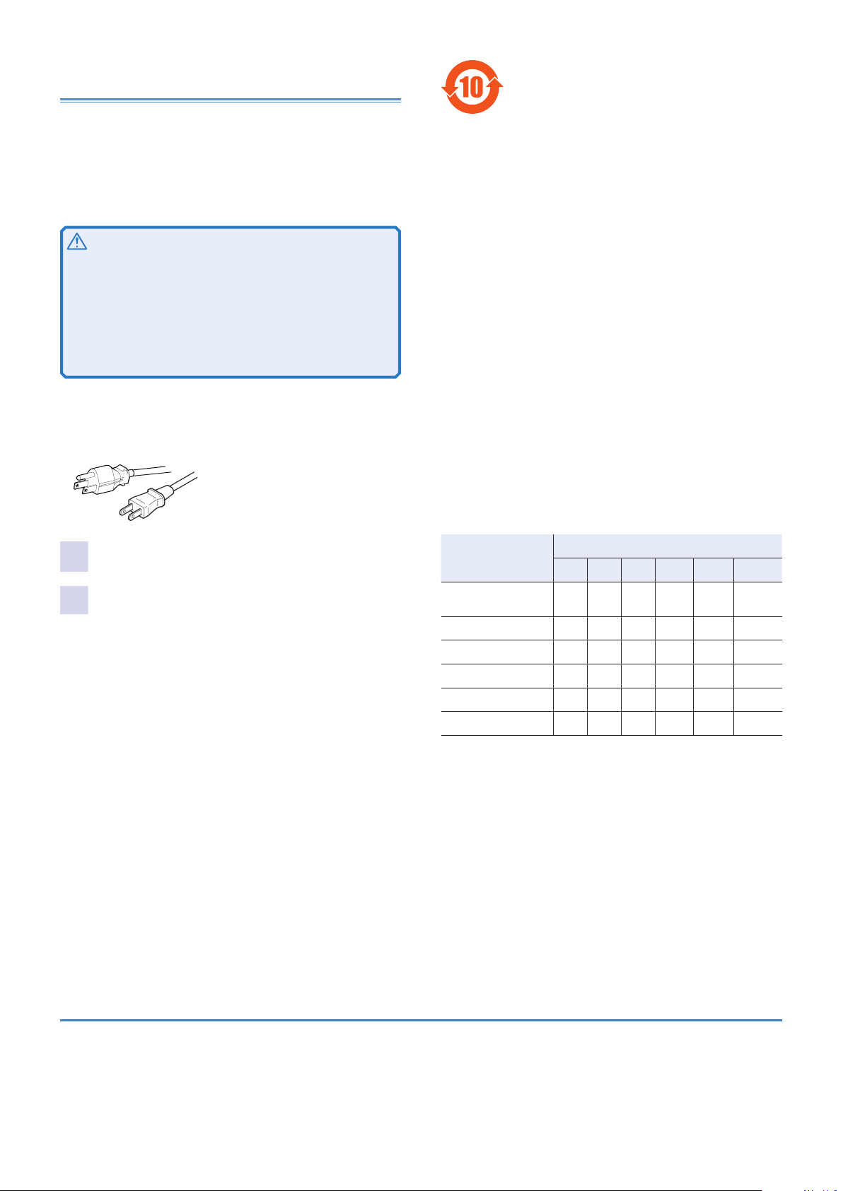
The outlets are designed for power plugs like those shown below.
NEMA5-15
NEMA1-15
环境保护使用期限
Environment-friendly Use Period
该标记为适用于在中华人民共和国销售的电子信息产品的环境保护使
用期限。
只要遵守有关该产品的安全及使用注意事项,从制造年月起计算,在
该年度内,就不会对环境污染、人身、财产产生重大的影响。
产品的废弃请遵守有关规定。
产品的制造年月可以在以下网址中确认。
http://www.kikusui.co.jp/pi/
This mark is used to indicate the period as Environment-friendly use period that applies to any of the Electronic Information Products sold in the
People’s Republic of China.
If you carefully observe the precaution of Safety and Usage for this product, no serious effect will be made to the environment, human body or
property during the period of the specied number of years from the manufacturing month/year of the product.
In case the product is disposed, please ensure to comply with the law or
regulation of local government in your region.
To check the manufacturing month/year of the product, visit the following
website.
http://www.kikusui.co.jp/pi/
毒有害物质或元素名称及含有标示
Name of hazardous materials and symbol of element in the equipment and
quantity
Turn the POWER switch off.
1
Connect the power cord of the load device to a front-
2
panel outlet.
部件名称
Name of part
印刷电路板组装品
Printed circuit board assemblies
显示器
Display
内部接线
Internal wirings
外壳
Enclosure
底盘组装品
Chassis assembly
辅助设备
Accessories
○ : 该部件所有均质材料的有毒有害物质的含量不超过 SJ/T11363-2006 标准所规定的
极限值要求。
×: 该部件至少有一种均质材料的有毒有害物质的含量超过 SJ/T11363-2006 标准所规
定的极限值要求。
○ : The content of toxic and hazardous substances or elements from the homogeneous
materials used in all appliance components does not exceed the limit dened in the SJ/
T11363-2006 standard.
×: The content of toxic and hazardous substances or elements from the homogeneous ma-
terials used in at least one of the applicable components does exceed the limit dened in
the SJ/T11363-2006 standard.
有毒有害物质或元素
Hazardous material and symbol of element
铅Pb汞Hg镉Cd六价铬
× ○ ○ ○ ○ ○
× ○ ○ ○ ○ ○
○ ○ ○ ○ ○ ○
× ○ ○ ○ ○ ○
× ○ ○ ○ ○ ○
○ ○ ○ ○ ○ ○
Cr(VI)
多溴联苯
PBB
多溴二苯醚
PBDE
The PCR-LE2 series is subject to export control laws.
Trademarks
All company names and product names used in the PCR-LE2
manual are trademarks or registered trademarks of their respective
companies.
Copyrights
The contents of the PCR-LE2 manual may not be reproduced, in
whole or in part, without the prior consent of the copyright holder.
The specifications of this product and the contents of this manual
are subject to change without prior notice.
14 PCR-LE2 series
 Loading...