

Kikusui PCR6000LE2, PCR9000LE2, PCR12000LE2, PCR18000LE2, PCR27000LE2 Setup Manual
PART NO. Z1-006-120, IB027733
(1pc.) [Z1-005-040]
PCR6000LE2/PCR9000LE2 only
Dec. 2014
Setup Guide
AC Power Supply PCR-LE2
seriess
PCR6000LE2
PCR9000LE2
PCR12000LE2
PCR18000LE2
PCR27000LE2
Thank you for purchasing the PCR-LE2 Series AC Power Supply.
The PCR-LE2 Series is a special version of the PCR-LE Series that
can produce highly pure AC signals through the combination of
its high-speed linear amplifier and arbitrary waveform synthesizer.
It features switchable single-phase, single-phase three-wire, and
three-phase outputs.
Checking the Package Contents
When you receive the product, check that all accessories are included and that the accessories have not been damaged during
transportation. If any of the accessories are damaged or missing,
contact your Kikusui agent or distributor. We recommend that you
save all packing materials, in case the product needs to be transported at a later date.
Accessory
If necessary, attach
Setup Guide (1pc.)
[Z1-006-120]
CD-ROM (1 pc.)
[SA-6060]
English: 1pc. [Z1-006-102]
Japanese: 1pc. [Z1-006-100]
Quick Reference Safety information
KIKUSUI ELECTRONICS CORP.
1-1-3, Higashiyamata, Tsuzuki-ku, Yokohama, 224-0023, Japan
TEL: +81-45-593-7570 Fax: +81-45-593-7571
WEBSITE
The newest version of the operation manual can be
downloaded from Download service of Kikusui website.
Printed in Japan © 2013
http://www.kikusui.co.jp/en
to the product.
Heavy object warning label
[A8-900-158]
PCR-LE2 manual
Features
The PCR-LE2 Series is equipped with the following features.
• Switchable between single-phase output, single-phase threewire output, and three-phase output
Three types of output are available on a single unit.
• Various power supply simulations
Power line abnormalities such as outages and voltage dips can
be simulated. This is a basic feature for power-supply-environment testing.
• Various measurements
The rms voltage and current, the peak voltage and current, the
active power, apparent power, and power factor of the output
can be measured. Harmonic analysis (up to the 40th harmonic)
can be performed on the output current.
• DC output
The PCR-LE2 Series can generate DC output (single-phase output or single-phase three-wire output only) and AC + DC output
(single-phase output only). This makes it possible to use the
PCR-LE2 Series in a wide variety of fields, including chemistry
and physics.
• Sequences
The output voltage, frequency, and waveform can be changed
over time. Power-supply-environment testing can be automated.
In addition to the AC output sequences, DC output (single-phase
output or single-phase three-wire output only) and AC + DC output (single-phase output only) sequences are also available. A
variety of standard tests can also be performed.
• Sensing and regulation adjustment
Even if the load device is at a remote location, the PCR-LE2 Series can stabilize the voltage across the load by correcting for
voltage drops.
There are two types of sensing: hard sensing (single-phase
output only) and soft sensing. The different types of sensing are
used depending on the load conditions and how you will use the
PCR-LE2 Series.
• Output current control
The output limit function can be used to limit the output current
(rms) to a fixed value to perform continuous operation. Continuity
tests on electrical equipment (such as switchboards, breakers,
and wiring devices) can be performed under stable conditions.
• Power management function (power saving function)
A sleep function, which turns the power units off to reduce power
consumption when output is not generated for the specified
length of time, and a power-saving function, which operates the
power units at the bare minimum settings as required by the supply load, are available.
• Memory function
Up to 99 entries of output frequency, voltage (AC or DC), and
waveform bank settings can be saved to the internal memory.
The contents of internal memory, panel settings, power line abnormality simulations, sequence data, and waveform bank data
can be saved to a USB memory device.
• External communications
The PCR-LE2 Series can be controlled remotely through its
RS232C interface. If an optional interface board is used, the
PCR-LE2 Series can be controlled remotely through USB, GPIB,
and LAN interfaces.
• External analog signal control (optional)
The EX05-PCR-LE/EX06-PCR-LE option enables you to control
the PCR-LE2 Series output using external analog signals.
PCR-LE2 series 1
About the PCR-LE2 Documentation
These manuals are intended for users of the PCR-LE2 Series AC
Power Supply and their instructors.
Explanations are given under the presumption that the reader has
knowledge related to electric safety tests.
You can view the PDF file using Adobe Reader 6.0 or later.
The HTML can be viewed using the following browser.
Browser: Microsoft Internet Explorer 9.0 or later
Every effort has been made to ensure the accuracy of this manual.
However, if you have any questions or find any errors or omissions,
please contact your Kikusui agent or distributor.
If you find any misplaced or missing pages in this manual, it will be
replaced. If the manual gets lost or soiled, a new copy can be provided for a fee. To replace or purchase a manual, please contact
your Kikusui agent or distributor. At that time, inform your agent or
distributor of the “Part No.” written on the front cover of this manual.
After you have finished reading this manual, store it so that you can
use it for reference at any time.
Notations used in the PCR-LE2 manual
In the PCR-LE2 manual, the PCR-LE2 Series AC Power Supply is
also referred to as the PCR-LE2 Series and the PCR-LE2.
The term “PC” is used to refer generally to both personal computers and workstations.
The screen captures used in this manual may differ from the actual
screens that appear on the PCR-LE2. The screen captures are
merely examples.
The following markings are used in the explanations in the manual.
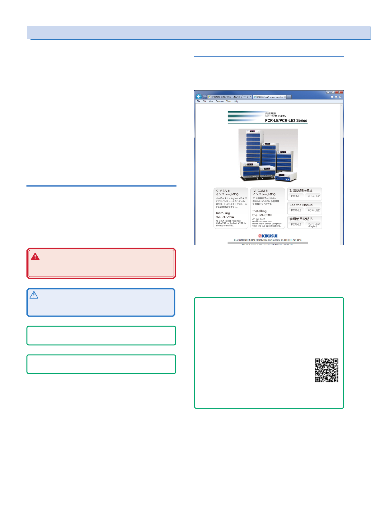
Contents of the Included CD-ROM
Put the included CD-ROM into the CD-ROM drive. In a few moments, a start window will appear. If the start window does not
appear, open the CD-ROM folder in Windows Explorer, and then
double-click index.html to display the start window.
WARNING
Indicates a potentially hazardous situation which, if ignored, could result in death or serious injury.
CAUTION
Indicates a potentially hazardous situation which, if ignored,
may result in damage to the product or other property.
- Note -
Indicates information that you should know.
- DESCRIPTION -
Explanation of terminology or operation principle.
(SHIFT+key name)
Indicates an operation that requires you to press a key indicated
in blue characters (the lower row of text to the left of the key)
while holding down the SHIFT key.
Accompanying CD-ROM contains following the items.
• KI-VISA x.x.x
• IVI-COM
• Operation Manual
Click the "See the Manual" to move to the Manual page.
- Tips -
How to view ePub les on a tablet
To view an ePub le on a tablet, an ePub reader (e.g., iBooks, Himawari Reader) must be installed in the tablet. You can download
ePub readers for free.
There are several ways to copy ePub les to your tablet, but we
recommend that you download them from the Kikusui Electronics
Corporation website.
1. Using a browser on your iPad, visit Kikusui Electronics Corporation website’s Operation Manual
Database (http://www.kikusui.co.jp/en/download/), and search for your PCR-LE2 series.
2. Tap the appropriate ePub le to download it.
When an ePub le is downloaded to your tablet, you can view it
even when the tablet is not connected to the Web.
2 PCR-LE2 series

Documentation Structure
The PCR-LE2 Series manual comprises the following documentation.
User’s Manual -Basic-
• Front panel and Rear panel
• Panel Operation Basics
• Selecting the Output Mode
• Setting the Output Voltage/ Frequency
• Turning Output On and Off
• Displaying Measurement Values
How to switch the display of measured value.
• Setting Limits
Limits can be placed on the PCR-LE2 output voltage setting and
frequency setting. They prevent damage to the load caused by
mistaken operations and limit the current that flows through the
load. You can set limits in advance according to the load conditions.
• Using Protection Functions
The PCR-LE2 has the following protection functions.
Input voltage drop protection
Overheat protection (OHP)
Overload protection
Internal semiconductor protection (OCP)
Output undervoltage protection (UVP)
Output overvoltage protection (OVP)
• Using Memory
You can store data to the PCR-LE2’s internal memory and save
data to a USB memory device.
User’s Manual -Specications-
Specifications contains the electrical specifications and outline
drawings.
User’s Manual -Appendix-
• Glossary, Operation Characteristics, Output and load
• Peak hold current measurement
• Sequence tutorial
• Option
• Factory Default Settings
• Maintenance
• Troubleshooting
• Alarms and Trouble
• Error Message
Setup Guide (This guide)
This guide is intended for first-time users of the product. It gives an
overview of the product, connecting procedures, etc. Please read
through and understand this guide before operating the product.
Quick Reference
The quick reference briefly explains the panel description and the
basic operation of the product.
Safety information
This document contains general safety precautions for this product.
Keep them in mind and make sure to observe them.
Programming Sheet
• Table for Recording Power Line Abnormality Simulation Operation Settings (XLS)
• Table for Recording Sequence Operation Settings (XLS)
User's Manual -Advanced-
• Using the synchronization Function
The synchronization function synchronizes the frequency and
phase of the PCR-LE2 output voltage with a 50 Hz or 60 Hz input
power supply.
• Using the Voltage Compensation Function
The compensation function compensates for voltage drops in the
load cables when the load is connected to the PCR-LE2 over a
long distance.
• Using Power Line Abnormality Simulations
In AC mode, you can simulate power supply line errors by stop-
ping the PCR-LE2 output and decreasing and increasing the
voltage (to simulate voltage dips and pops).
• Using the Sequence Function
A sequence is a series of settings - values such as the output
voltage, frequency, and time - that are saved in advance and
are then recalled and automatically carried out in order at a later
time.
• Using the Harmonic Current Analysis Function
You can perform harmonic analysis of the output current.
• Generating Special Waveforms (Waveform bank)
You can generate peak-clipped sine waveforms.
• Setting the Output Impedance
The PCR-LE2 output impedance (output resistance) is approxi-
mately 0 Ω. Commercial power supplies have an impedance
(resistance) of several milliohms to several ohms. You can set
the PCR-LE2 output impedance. This enables you to simulate
the same environment as that which is provided by commercial
power supplies.
• Setting Soft Starts (The voltage rise time)
To prevent the output from being turned off (the alarm from be-
ing activated) and the voltage from dropping due to the load
device’s inrush current that exceeds the rated capacity of the
PCR-LE2, you can control the inrush current by having the output
voltage rise gradually when the output is turned on.
• Fixing the Internal Vcc
To minimize loss in the linear amplifier section, the PCR-LE2 au-
tomatically adjusts the linear amplifier supply voltage (Vcc) to a
level that is suitable for the output voltage. You can fix the Vcc
voltage of the PCR-LE2. This is useful when you want to prioritize
the output voltage response over the product’s efficiency.
• Selecting the Response
The PCR-LE2 uses a high-speed amplifier. Depending on the
load circuits (especially in the case of capacitive loads) and the
wiring conditions, the output may become unstable may oscillate. You can set the response speed of the internal amplifier
according to the load conditions and how you will use the PCRLE2.
• Using the Power Management Functions
The PCR-LE2 has the following two power management func-
tions: a sleep function and a power-saving function
• External analog signal control (optional)
You can use the optional analog signal interface board to control
the product with external analog signals.
Communication Interface Manual
This manual contains details about remote control.
Interface manual is written for readers with sufficient basic knowledge of how to control instruments using a personal computer.
PCR-LE2 series 3
PCR-LE2 Series models
Three-phase output Single-phase three-wire output
1group
power unit
V
Stopper
The PCR-LE2 Series generates single-phase output. The following
models are available
Model Rated output capacity Maximum output current
Singlephase,
Three-phse
PCR6000LE2 6 kVA 4 kVA 60 A 30 A 20 A 10 A
PCR9000LE2 9 kVA 6 kVA 90 A 45 A 30 A 15 A
PCR12000LE2 12 kVA 8 kVA 120 A 60 A 40 A 20 A
PCR18000LE2 18 kVA 12 kVA 180 A 90 A 60 A 30 A
PCR27000LE2 27 kVA 18 kVA 270 A 135 A 90 A 45 A
This product consists of three power unit groups.
Model Output capacity per group
PCR6000LE2 2 kVA
PCR9000LE2 3 kVA
PCR12000LE2 4 kVA
PCR18000LE2 6 kVA
PCR27000LE2 9 kVA
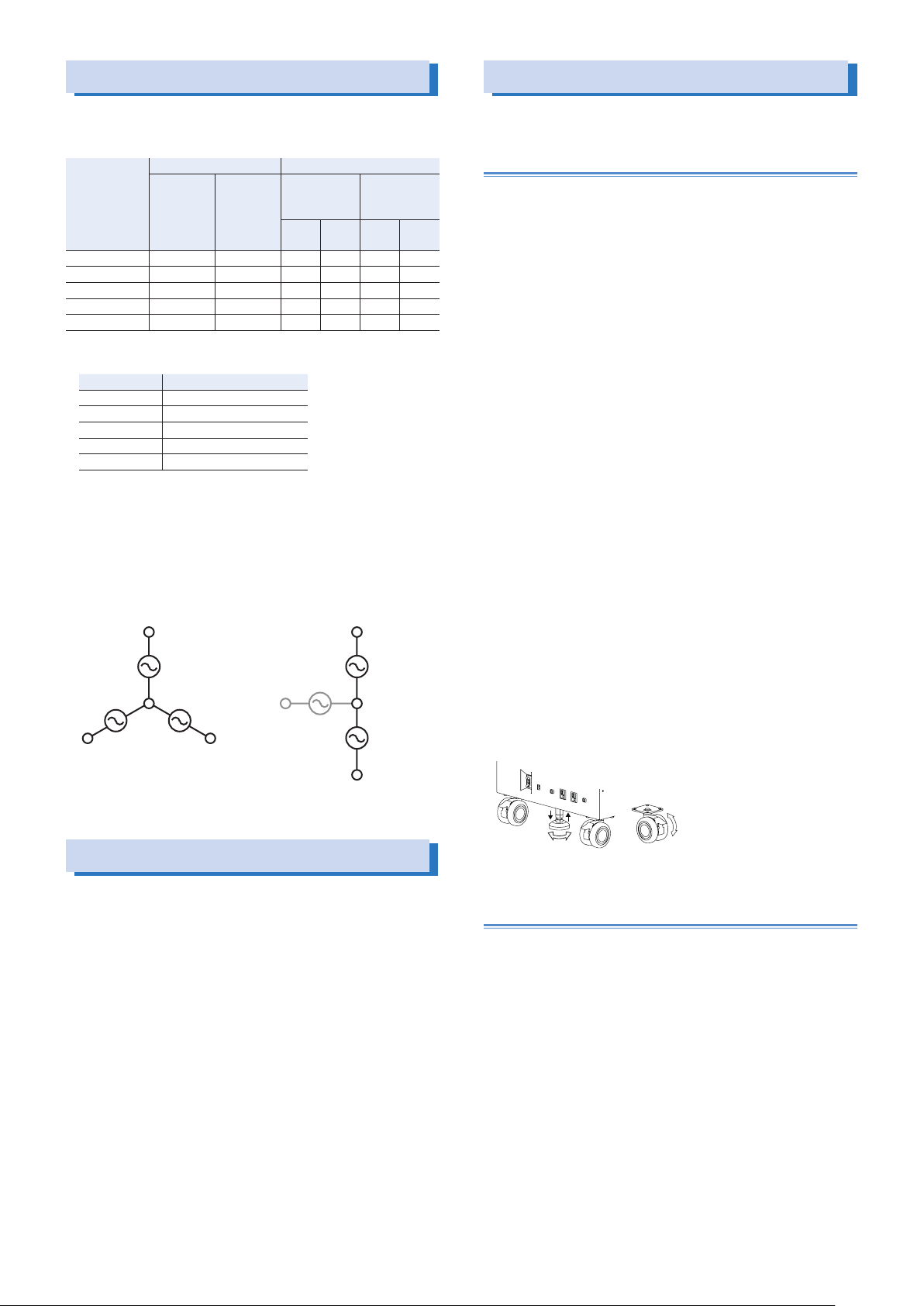
During single-phase output, all groups are used.
During single-phase three-wire output or three-phase output, each
phase (U, V and W) is assigned to a separate group.
During single-phase three-wire output, the phase W group is not
used. During three-phase output, all groups are used.
U U
1group
power unit
V
1group
power unit
Singlephase
three-wire
W
Single-phase Single-phase
100 V
output
1group
nonoperating
power unit
W
200 V
output
three-wire,
Three-phse
100 V
output
1group
power unit
1group
power unit
200 V
output
Moving the product
Precautions when moving the PCR6000LE2/
PCR9000LE2
Note the following points when moving the product to the installation location or when transporting the product.
●Raise the stopper.
Moving the product with the stopper lowered may cause injuries
due to the product falling over.
●Unlock the casters.
●Do not move the product by yourself.
Be sure to have two or more people move the product. Exercise
special care when carrying the product over a slope or across
steps.
Hold the product from underneath.
Check the product’s weight before you transport it. The weight is
displayed in the bottom of the rear panel.
If you are using a forklift, be sure to slide the forks under the bottom of the product, check that the product is stable, and then
raise the product.
If you are using a band or similar item to raise the product with a
crane, be sure to slide the band under the bottom of the product,
check that the product is stable, and then raise the product.
●When you move the product, do not tip the product on its side or
turn it upside down.
Locking the casters and using the stopper
This product has casters on its bottom side, so it is easy to move
the product. To ensure that the product is not moved accidentally
while it is being operated, use the stopper to fix the product in
place, and lock the casters.
Looking down at the stopper from above, turning the stopper to the
left (counterclockwise) raises the stopper, and turning the stopper
to the right (clockwise) lowers the stopper.
Lowering the lock lever on a caster locks the caster, and raising the
lock lever unlocks the caster.
Precautions Concerning Installation
When installing this product, be sure to observe the precautions provided in “Precautions Concerning Installation Location” in the Safety
information manual. Items specific to this product are given below.
●When you install the product, be sure to observe the temperature
and humidity ranges indicated below.
Operating temperature range: 0 °C to 50 °C (32 °F to 122 °F)
Operating humidity range: 20 %rh to 80 %rh (no condensation)
●When you store the product, be sure to observe the temperature
and humidity ranges indicated below.
Storage temperature range: -10 °C to 60 °C (14 °F to 140 °F)
Storage humidity range: 90 %rh or less (no condensation)
●Allow at least 20 cm of space between the air inlet/outlet and the
wall (or obstacles).
●Fix PCR6000LE2s and PCR9000LE2s to the floor using L-shaped
or other similar brackets.
Base Hold Angles (OP03-KRC) are available as options.
Down Up
Free
Lock
Precautions when moving the PCR12000LE2/
PCR18000LE2/ PCR27000LE2
The PCR12000LE2/ PCR18000LE2/ PCR27000LE2 cannot be
moved after it has been installed. If you need to move it, contact
your Kikusui agent or distributor.
4 PCR-LE2 series
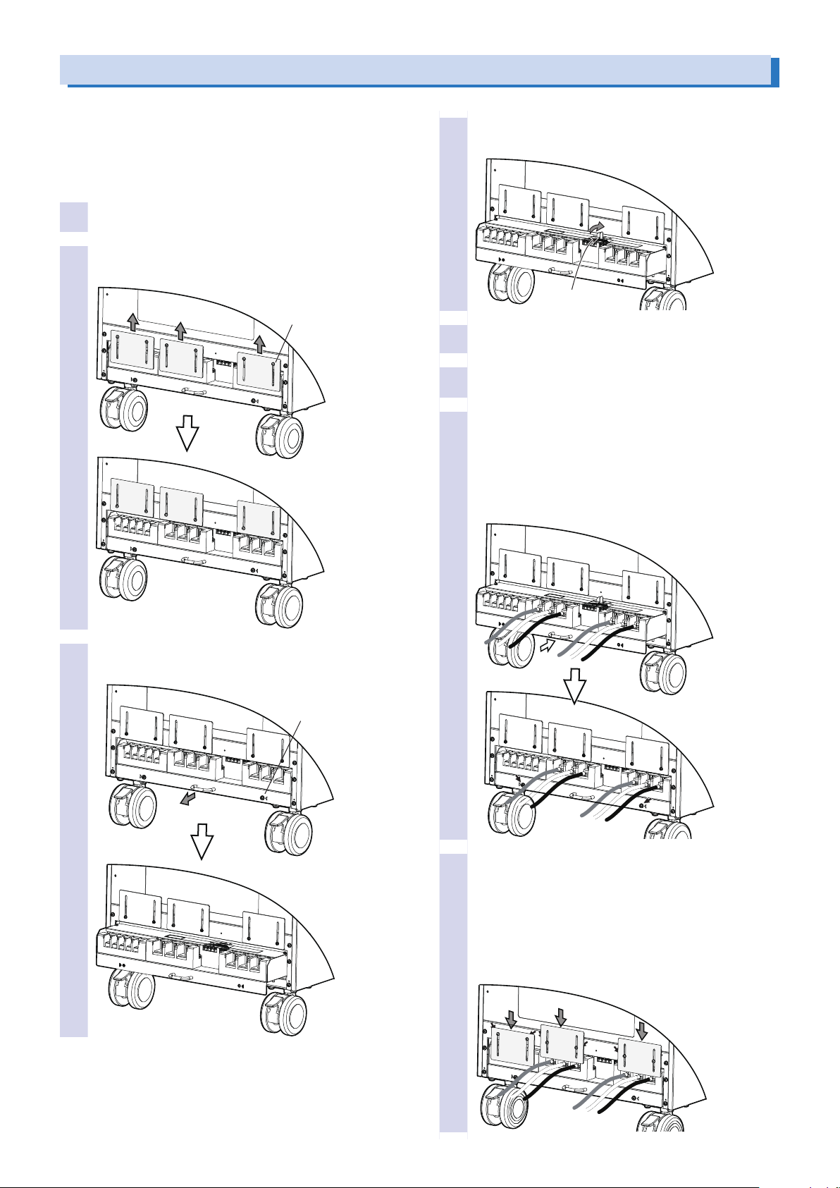
Handling the Terminal Block Tray (PCR6000LE2/ PCR9000LE2)
The PCR-LE2 Series AC INPUT, OUTPUT terminal block, SENSING
terminal block, and J1 to J4 connectors are designed so that they
can only be wired after you first pull out the terminal block tray.
The terminal box covers ensure that you don’t touch the unwired
terminals. Use a Phillips-head screwdriver to insert and remove the
screws.
Check that the POWER switch is turned off.
1
Loosen the six terminal box cover screws, and then
2
slide the three covers up.
M3 x 6
Pull out the stopper to lock the terminal block tray
4
in place.
Stopper
Connect the wires and cables to the terminal block
5
and connectors as necessary.
Return the stopper to its previous position.
6
Return the terminal block tray to its previous posi-
7
tion, and then attach the two screws that you removed in step 3
If you do not insert the terminal block tray all the way into
its storage compartment, an electric current will not flow
through the PCR-LE2 even if the POWER switch is turned
on.
Remove the two terminal block tray screws, and
3
then pull the tray out.
M4 x 2
Slide the two terminal box covers down until they
8
are touching the wires, and then use the four
screws to x the terminal box covers in place. Slide
the terminal box cover all the way down if none of
their terminals have wires connected to them, and
use the two screws to x the covers in place.
The figure below is an example for when the OUTPUT terminal blocks for single-phase output are in use.
PCR-LE2 series 5
 Loading...