

Kikusui PCR 2000M User Manual
USERʼS MANUAL
AC POWER SUPPLY
PCR-M series
PCR 500M
PCR1000M
Part No. IB016983
May. 2010
PCR2000M

al w
an
Operation Man ual
Setup Guide
The setup guide guide is intended for fi rst-time users of the PCR-M series. It gi v es an o v ervie w of the
PCR-M series, connecting procedures, safety precautions, etc. Please read through and understand this
guide before operating the product.
Quick Reference
The quick reference briefl y e xplains the panel description and the basic operation of the PCR-M.
User’ s Manual (This manual)
User’ s manual is intended for fi rst-time users of the PCR-M series. It gi v es an o v ervie w of the PCR-M
series and describes v arious settings, measurement procedures, maintenance, safety precautions, etc.
Communication Interf ace Manual
The Communication Interf ace Manual e xplains the settings and commands for remotely controlling the
PCR-M series, using the communication interf ace and gi v es sample programs. The interf ace Manual is
pro vided on the accompan ying CD-R OM.
The interf ace manual is written for readers with suf fi cient basic kno wledge of ho w to control instru ments using a personal computer .
Please read through and understand the Operation Manual before operating the product. After reading,
ays k eep the manuals nearby so that you may refer to it as needed. When mo ving the product to another
location, be sure to bring the manuals as well.
If you fi nd an y incorrectly arranged or missing pages in the manual, the y will be replaced. If the manual
gets lost or soiled, a ne w cop y can be pro vided for a fee. In either case, please contact Kikusui distrib utor/
agent, and pro vide the “Kikusui P art No. ” gi v en on the co v er .
The Operation Manual has been prepared with the utmost care; ho we v er , if you ha v e an y questions, or note
y errors or omissions, please contact Kikusui distrib utor/agent.
Microsoft and W indo ws are re gistered trademarks of Microsoft Corporation in the United States and/or
other countries.
Other compan y names and product names used in this manual are generally trademarks or re gistered trade marks of the respecti v e companies.
Reproduction and reprinting of operation manual, whole or partially , without our permission is prohibited.
Both unit specifi cations and manual contents are subject to change without notice.
Cop yright© 2008-2010 Kikusui Electronics Corporation
F
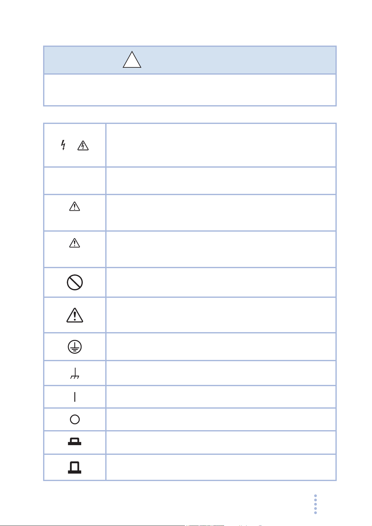
Saf ety Symbols
!
or the saf e use and saf e maintenance of this product, the f ollo wing symbols are
used throughout this man ual and on the product. Note the meaning of each of the
symbols to ensure saf e use of the product. (Not all symbols ma y be used.)
Indicates that a high v oltage (o v er 1 000 V) is used here .
or
ouching the par t causes a possib ly f atal electr ic shoc k. If ph ysical
contact is required b y y our w or k, star t w or k only after y ou make sure
that no voltage is output here.
T
DANGER
WARNING
CAUTION
Indicates an imminently hazardous situation which, if ignored, will result
in death or serious injury.
Indicates a potentially hazardous situation which, if ignored, could result
in death or serious injury.
Indicates a potentially hazardous situation which, if ignored, may result
in damage to the product and other property.
Shows that the act indicated is prohibited.
Indicates a general danger, warning, or caution.
When this symbol is marked on the product, see the relevant sections in
this manual.
Protective conductor terminal.
PCR-M
Chassis (frame) terminal.
On (supply)
Off (supply)
In position of a bi-stable push control
Out position of a bi-stable push control
3
Safety Precautions
!
The following safety precautions must be observed to avoid fire hazards, electric
shock, accidents, and other failures. Keep them in mind and make sure to observe
them.
Using the product in a manner that is not specified in this manual may impair the
protection functions provided by the product.
Users
Operation
ual
an
M
Purpose of
use
Input power
Line
Voltage
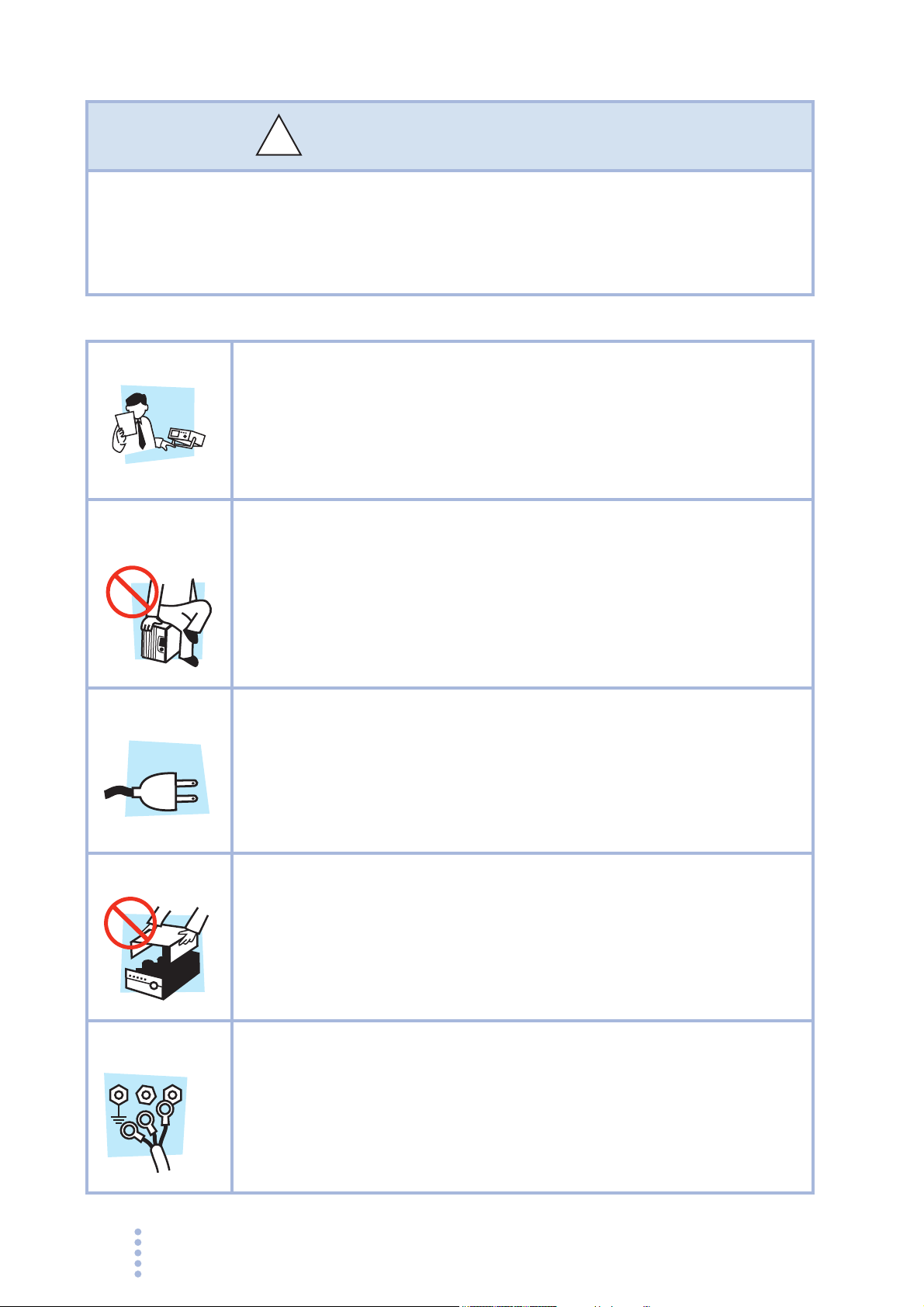
• This product must be used only by qualified personnel who
understand the contents of this operation manual.
• If unqualified personnel is to use the product, be sure the product is
handled under the supervision of qualified personnel (those who have
electrical knowledge). This is to prevent the possibility of personal
injury.
• Never use the product for purposes other than the product's intended
use.
• This product is not designed or manufactured for general home or
consumer use.
• Use the product within the rated input power voltage range.
• For applying power, use the power cord provided. For details, see the
respective page in this manual.
• This product is designed as an equipment of IEC Overvoltage
Category II (energy-consuming equipment supplied from the fixed
installation).
Cover
Grounding
N
G
4 PCR-M
L
• Some parts inside the product may cause physical hazards. Do not
remove the external cover.
• This product is an IEC Safety Class I equipment (equipment with a
protective conductor terminal). To prevent the possibility of electric
shock, be sure to connect the protective conductor terminal of the
product to electrical ground (safety ground).
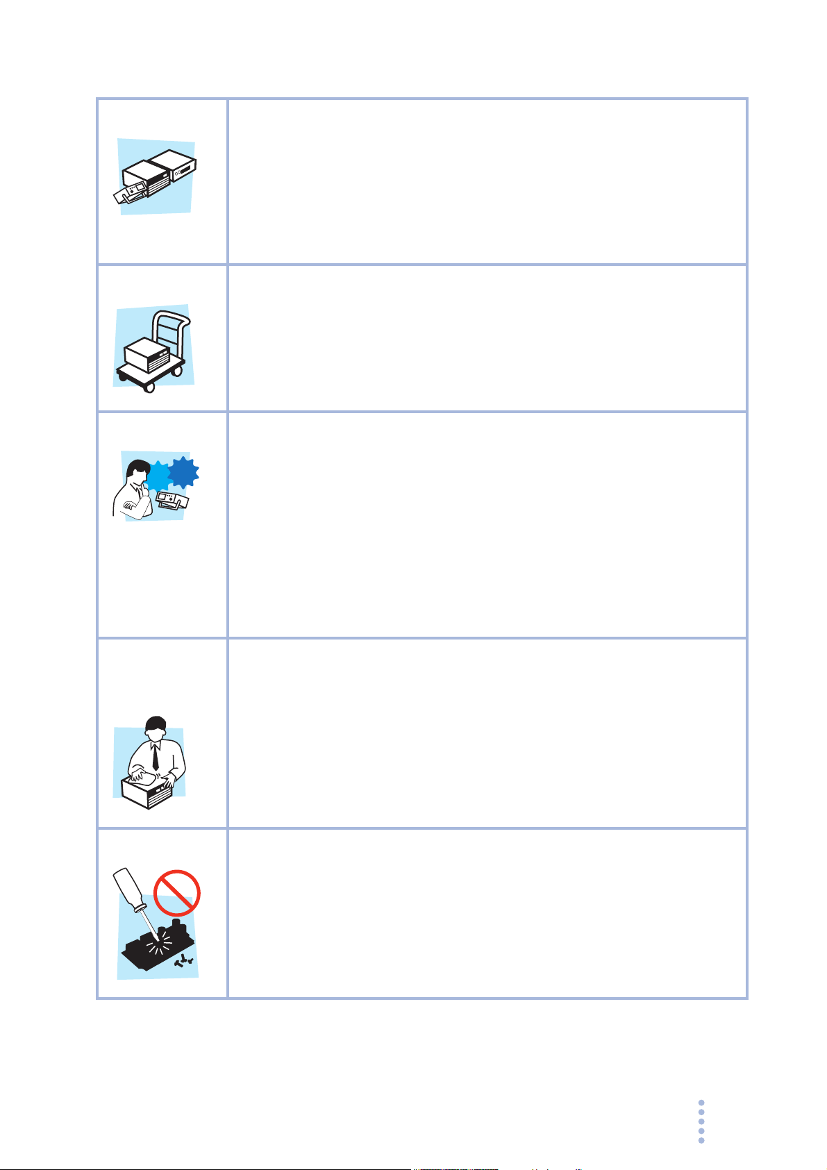
Installation
• This product is designed for safe indoor use. Be sure to use it indoors.
• When installing this product, be sure to observe the description in
section 2.2, “Precautions Concerning Installation Location” in this
manual.
• When connecting the power cable to a switchboard, be sure the work
is performed by a qualified and licensed electrician or is conducted
under the direction of such a person.
Relocation
Operation
Check?
Maintenance
and
inspection
• Turn off the POWER switch, and disconnect all cables before
relocating the product.
• When relocating the product, be sure to include the manual.
• Before using the product, be sure to check the input power voltage
and that there is no abnormality in the appearance of the power cord.
Be sure to remove the power plug from the outlet before checking it.
• If a malfunction or abnormality is detected on the product, stop using it
immediately, and remove the power plug from the outlet. Make sure
the product is not used until it is completely repaired.
• Use cables or wires with sufficiently large current capacity for output
wires and load cables.
• Do not disassemble or modify the product. If you need to modify the
product, contact your Kikusui distributor/agent.
• To prevent the possibility of electric shock, make sure to unplug the
power plug before carrying out maintenance or inspection.
• Do not remove the external cover during maintenance or inspection.
• To maintain the performance and safe operation of the product, it is
recommended that periodic maintenance, inspection, cleaning, and
calibration be performed.
Service
PCR-M 5
• Kikusui service engineers will perform internal service on the product.
If the product needs adjustment or repairs, contact your Kikusui
distributor/agent.

How to Read This Manual
Introduction
This manual is intended for first-time users of the PCR-M series. It gives an overview
of the PCR-M series and describes various settings, measurement procedures,
maintenance, safety precautions, etc.
Read this manual thoroughly to use the functions of the PCR-M series effectively.
You can also review this manual when you are confused about an operation or when a
problem occurs.
How to read this manual
This manual is designed to be read from beginning to end. We recommend that you
read the manual thoroughly from the beginning before using the PCR-M for the first
time.
Intended readers of this manual
This manual is intended for users of the PCR-M series AC Power Supply or persons
teaching other users on how to operate the PCR-M series.
It assumes that the reader has knowledge about electrical aspects of AC power
supplies.
Information on SCPI commands is provided with the premise that the reader has
sufficient knowledge about controlling instruments using a personal computer.
6 PCR-M

Structure of this manual
Below is the structure of the manual. A summary of each chapter is provided.
Chapter1 General Description
This chapter gives a general description and introduces the features of the PCR-M.
Chapter2 Installation and Preparation
This chapter describes the procedures from unpacking to installation.
Chapter3 Operation
This chapter describes the operations of the PCR-M and procedure for controlling the
output using external analog signals.
Chapter4 Remote Control
This chapter gives an overview of remote control and describes how to install the
instrument driver and software application.
Chapter5 Maintenance
This chapter describes maintenance. Conduct periodic maintenance and calibration to
maintain the initial performance as long as possible.
Chapter6 Specifications
This chapter describes the electrical, mechanical, and optional interface board
specifications of the PCR-M.
Appendix
PCR-M 7
Notations used in the manual
• In the interest of brevity, the PCR-M series AC power supply shall be hereafter
referred to as the "PCR-M series" or the "power supply".
• The word computer used in the text is a collective term for personal computers
and workstations.
• The following markings are used in the explanations in the text.
WARNING
Indicates a potentially hazardous situation which, if ignored, could result in
death or serious injury.
CAUTION
Indicates a potentially hazardous situation which, if ignored, may result in
damage to the product and other property.
Indicates information that you should know.
DESCRIPTION
Explanation of terminology or operation principle.
See
Indicates reference to detailed information.
>
Indicates menu settings that you select. The menu item to the left of the >
symbol is a higher level menu.
SHIFT+key name (marked in blue)
Indicates an operation in which a key marked in blue is pressed while
holding down the SHIFT key.
8 PCR-M

Contents
Safety Symbols - - - - - - - - - - - - - - - - - - - - - - - - - - - - - - - - - - - - - - - - - - - - - - - - - 3
Safety Precautions - - - - - - - - - - - - - - - - - - - - - - - - - - - - - - - - - - - - - - - - - - - - - - - 4
How to Read This Manual - - - - - - - - - - - - - - - - - - - - - - - - - - - - - - - - - - - - - - - - - 6
Contents - - - - - - - - - - - - - - - - - - - - - - - - - - - - - - - - - - - - - - - - - - - - - - - - - - - - - 9
Contents by Function - - - - - - - - - - - - - - - - - - - - - - - - - - - - - - - - - - - - - - - - - - - - 11
Front panel - - - - - - - - - - - - - - - - - - - - - - - - - - - - - - - - - - - - - - - - - - - - - - - - - - - 12
Rear panel - - - - - - - - - - - - - - - - - - - - - - - - - - - - - - - - - - - - - - - - - - - - - - - - - - - - 14
Chapter 1 General Description
1.1 Overview- - - - - - - - - - - - - - - - - - - - - - - - - - - - - - - - - - - - - - - - - - - - - - - - -16
1.2 Options- - - - - - - - - - - - - - - - - - - - - - - - - - - - - - - - - - - - - - - - - - - - - - - - - - 17
Chapter 2 Installation and Preparation
2.1 Checking the Package Contents - - - - - - - - - - - - - - - - - - - - - - - - - - - - - - - - 20
2.2 Precautions Concerning Installation Location - - - - - - - - - - - - - - - - - - - - - - - 21
2.3 Precautions to Be Taken When Moving the Product - - - - - - - - - - - - - - - - - - 22
2.4 Attachment to the Rack Mount Frame - - - - - - - - - - - - - - - - - - - - - - - - - - - - 22
2.5 Attachment of the Optional Interface Board - - - - - - - - - - - - - - - - - - - - - - - - 24
2.6 Connecting the Power Cord - - - - - - - - - - - - - - - - - - - - - - - - - - - - - - - - - - - 25
2.7 Turning the Power On - - - - - - - - - - - - - - - - - - - - - - - - - - - - - - - - - - - - - - - 28
2.8 Connecting the Load - - - - - - - - - - - - - - - - - - - - - - - - - - - - - - - - - - - - - - - - 30
Features - - - - - - - - - - - - - - - - - - - - - - - - - - - - - - - - - - - - - - - - - - - - - - 16
Accessories - - - - - - - - - - - - - - - - - - - - - - - - - - - - - - - - - - - - - - - - - - - - 20
Connecting to the OUTPUT terminal block - - - - - - - - - - - - - - - - - - - - - - 30
Connecting to the OUTPUT outlet - - - - - - - - - - - - - - - - - - - - - - - - - - - - 32
When the load is located at a distance from the PCR-M - - - - - - - - - - - - 33
Chapter 3 Operation
3.1 Switching the Output Mode- - - - - - - - - - - - - - - - - - - - - - - - - - - - - - - - - - - -36
3.2 Setting the Voltage Range - - - - - - - - - - - - - - - - - - - - - - - - - - - - - - - - - - - - 37
3.3 Setting the Voltage - - - - - - - - - - - - - - - - - - - - - - - - - - - - - - - - - - - - - - - - - 38
3.4 Setting the Frequency - - - - - - - - - - - - - - - - - - - - - - - - - - - - - - - - - - - - - - - 39
3.5 Turning the OUTPUT On/Off- - - - - - - - - - - - - - - - - - - - - - - - - - - - - - - - - - - 40
3.6 Measured value display - - - - - - - - - - - - - - - - - - - - - - - - - - - - - - - - - - - - - - 42
3.7 Setting the limit value - - - - - - - - - - - - - - - - - - - - - - - - - - - - - - - - - - - - - - - - 44
3.8 Using Memories - - - - - - - - - - - - - - - - - - - - - - - - - - - - - - - - - - - - - - - - - - - 46
Saving to the memory - - - - - - - - - - - - - - - - - - - - - - - - - - - - - - - - - - - - - 46
Recalling the memory - - - - - - - - - - - - - - - - - - - - - - - - - - - - - - - - - - - - - 47
3.9 Switching from remote control to local control- - - - - - - - - - - - - - - - - - - - - - - 47
3.10 Locking (Prohibiting) the Panel Operation - - - - - - - - - - - - - - - - - - - - - - - - - 48
3.11 Protection Functions and Alarm Errors- - - - - - - - - - - - - - - - - - - - - - - - - - - - 48
3.11.1 Alarm Occurrence- - - - - - - - - - - - - - - - - - - - - - - - - - - - - - - - - - - - - 49
PCR-M 9

Clearing Alarms - - - - - - - - - - - - - - - - - - - - - - - - - - - - - - - - - - - - - - - - -49
Clearing Errors - - - - - - - - - - - - - - - - - - - - - - - - - - - - - - - - - - - - - - - - - -49
Alarm or error number, description, and remedy - - - - - - - - - - - - - - - - - - 50
3.11.2 Operation when the protection function is activated - - - - - - - - - - - - -51
3.11.3 Steps to be taken if the circuit breaker trips (PCR2000M only)- - - - - -51
3.12 Setting the Configuration- - - - - - - - - - - - - - - - - - - - - - - - - - - - - - - - - - - - - -52
3.13 Factory Default Settings (Initialization) - - - - - - - - - - - - - - - - - - - - - - - - - - - -56
3.14 Controlling the Output Using External Analog Signals (Option) - - - - - - - - - - -57
Varying the voltage of the output AC waveform using DC signals (EXT-AC
mode) - - - - - - - - - - - - - - - - - - - - - - - - - - - - - - - - - - - - - - - - - - - -58
Amplifying the input waveform (EXT-DC mode) - - - - - - - - - - - - - - - - - - -59
Chapter 4 Remote Control
4.1 Overview - - - - - - - - - - - - - - - - - - - - - - - - - - - - - - - - - - - - - - - - - - - - - - - - -62
4.2 Installation - - - - - - - - - - - - - - - - - - - - - - - - - - - - - - - - - - - - - - - - - - - - - - - -62
4.2.1 Installing the VISA Library - - - - - - - - - - - - - - - - - - - - - - - - - - - - - - -63
4.2.2 Installing the Software Application- - - - - - - - - - - - - - - - - - - - - - - - - -64
4.3 Command Details- - - - - - - - - - - - - - - - - - - - - - - - - - - - - - - - - - - - - - - - - - -64
Chapter 5 Maintenance
5.1 Cleaning - - - - - - - - - - - - - - - - - - - - - - - - - - - - - - - - - - - - - - - - - - - - - - - - -66
5.1.1 Cleaning the Panels - - - - - - - - - - - - - - - - - - - - - - - - - - - - - - - - - - -66
5.1.2 Cleaning the Dust Filter - - - - - - - - - - - - - - - - - - - - - - - - - - - - - - - - -66
5.2 Calibration - - - - - - - - - - - - - - - - - - - - - - - - - - - - - - - - - - - - - - - - - - - - - - - -68
5.3 Troubleshooting - - - - - - - - - - - - - - - - - - - - - - - - - - - - - - - - - - - - - - - - - - - -69
Chapter 6 Specifications
6.1 Specifications- - - - - - - - - - - - - - - - - - - - - - - - - - - - - - - - - - - - - - - - - - - - - -72
Electrical specifications - - - - - - - - - - - - - - - - - - - - - - - - - - - - - - - - - - - -72
General Specifications - - - - - - - - - - - - - - - - - - - - - - - - - - - - - - - - - - - - 74
RS232C interface specifications - - - - - - - - - - - - - - - - - - - - - - - - - - - - - 75
GPIB interface specifications (IB21 option) - - - - - - - - - - - - - - - - - - - - - -75
USB interface specifications (US21 option) - - - - - - - - - - - - - - - - - - - - - -75
Common interface specifications - - - - - - - - - - - - - - - - - - - - - - - - - - - - -75
Analog interface specifications (EX04-PCR-M option) - - - - - - - - - - - - - - 76
6.2 Dimensions - - - - - - - - - - - - - - - - - - - - - - - - - - - - - - - - - - - - - - - - - - - - - - -77
Appendix
A.1 Output and Load - - - - - - - - - - - - - - - - - - - - - - - - - - - - - - - - - - - - - - - - - - -80
Rated output current of AC mode - - - - - - - - - - - - - - - - - - - - - - - - - - - - -80
Rated output current of DC mode - - - - - - - - - - - - - - - - - - - - - - - - - - - - 82
A.2 Overload Protection Functions- - - - - - - - - - - - - - - - - - - - - - - - - - - - - - - - - -82
A.3 AC+DC mode - - - - - - - - - - - - - - - - - - - - - - - - - - - - - - - - - - - - - - - - - - - - -84
A.4 Glossary - - - - - - - - - - - - - - - - - - - - - - - - - - - - - - - - - - - - - - - - - - - - - - - - -85
Index
10 PCR-M
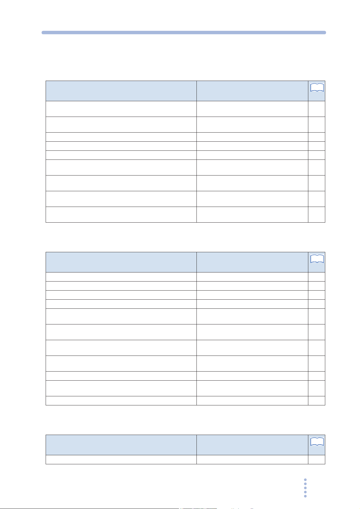
Contents by Function
Preparation
Situation Heading
What is the input rating? section 2.6, “Connecting the Power Cord,”
“Electrical specifications”
How much space is necessary around the exhaust ports on
the rear panel?
What kind of wires should be used to connect the load? section 2.8, “Connecting the Load” 30
Would like to set a voltage limit to protect the load. section 3.7, “Setting the limit value” 44
Would like to prevent overcurrent to protect the load. section 3.7, “Setting the limit value” 44
Would like to set the phase angle when the output is turned
on.
Would like to set the communication parameters of remote
control.
Would like to install the optional interface board. section 2.5, “Attachment of the Optional
Would like to rack mount the PCR-M. What do I need to
prepare?
section 2.2, “Precautions Concerning
Installation Location”
" OUTPUT on phase”
section 3.12, “Setting the Configuration”
Interface Board”
section 2.4, “Attachment to the Rack Mount
Frame,” section 6.2, “Dimensions”
See
page
25
72
21
41
52
24
24
77
Operation
Situation Heading
Would like to test drastic changes in voltage or frequency. section 3.8, “Using Memories” 46
Would like to superimpose DC voltage on the AC voltage. section 1.2, “Options” 17
Would like to preset multiple voltages that will be used.
Would like to know the load power. “Display on the lower numeric display” 42
Would like to know the peak value of current in addition to the
rms value.
Would like to use the PCR-M as a power amplifier. section 3.14, “Controlling the Output Using
Would like to disable panel operation. section 3.10, “Locking (Prohibiting) the Panel
Would like to reset the PCR-M to factory default settings. section 3.13, “Factory Default Settings
Would like to use the accompanying CD-ROM. section 4.2, “Installation” 62
An alarm occurred. Would like to correct it immediately. section 3.11, “Protection Functions and
Not working correctly. Is the PCR-M broken? section 5.3, “Troubleshooting” 69
“Saving to the memory”
section 3.6, “Measured value display”
External Analog Signals (Option)”
Operation”
(Initialization)”
Alarm Errors”
See
page
46
42
57
48
56
48
Maintenance
Situation Heading
Would like to clean the dust filter. section 5.1.2, “Cleaning the Dust Filter” 66
PCR-M 11
See
page
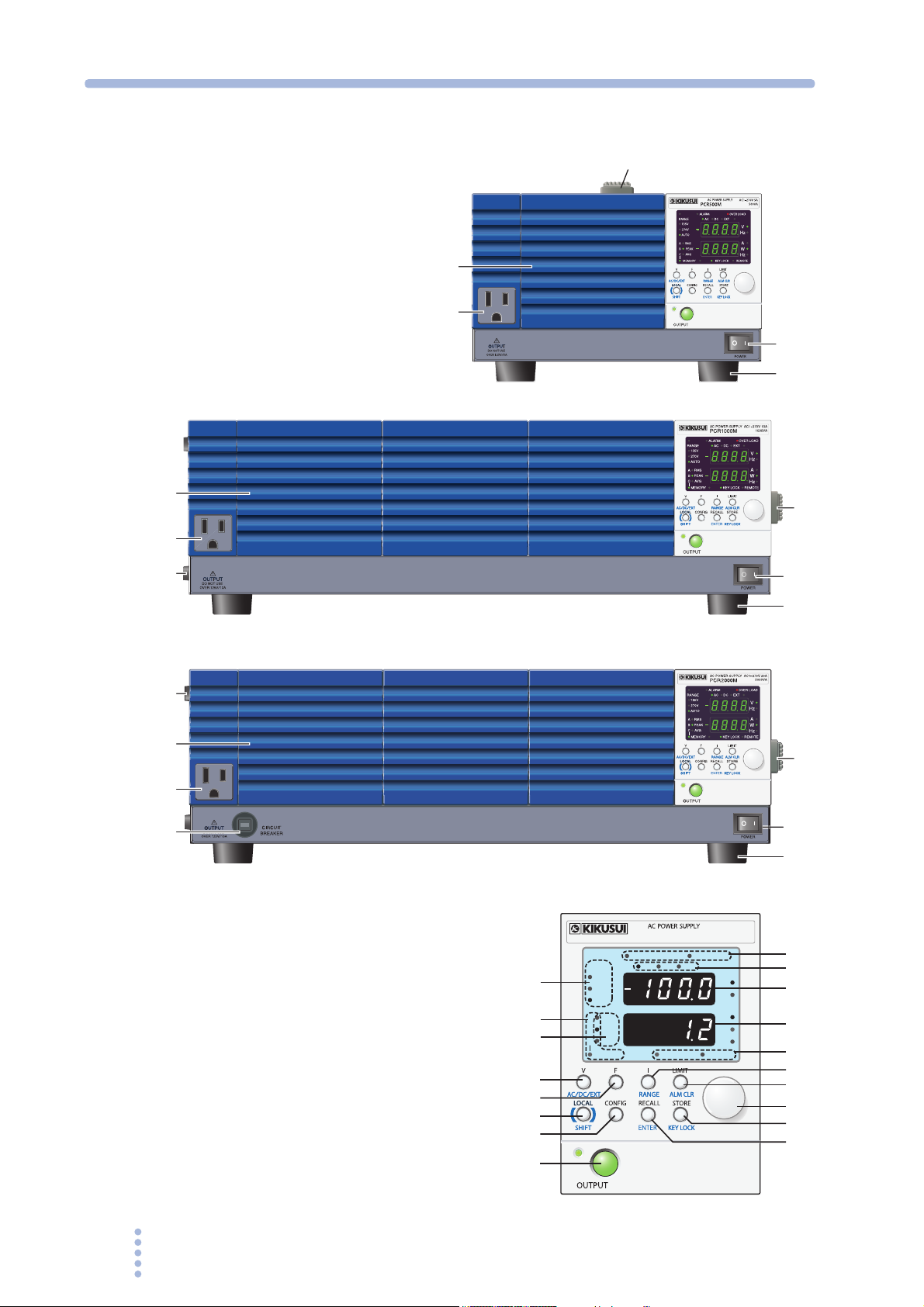
Front panel
PCR1000M
5
PCR500M
4
3
1
2
4
3
2
PCR2000M
2
4
3
6
Operation Panel
5
1
2
5
1
2
7
8
9
10
11
15
16
17
18
19
14
13
12
24
23
22
21
RANGE
135V
270V
AUTO
RMS
A
PEAK
B
C
MEMORY
ALARM
AC
-
AVG
DC
KEY LOCK
OVER LOAD
EXT
V
Hz
A
W
Hz
REMOTE
20
12 PCR-M
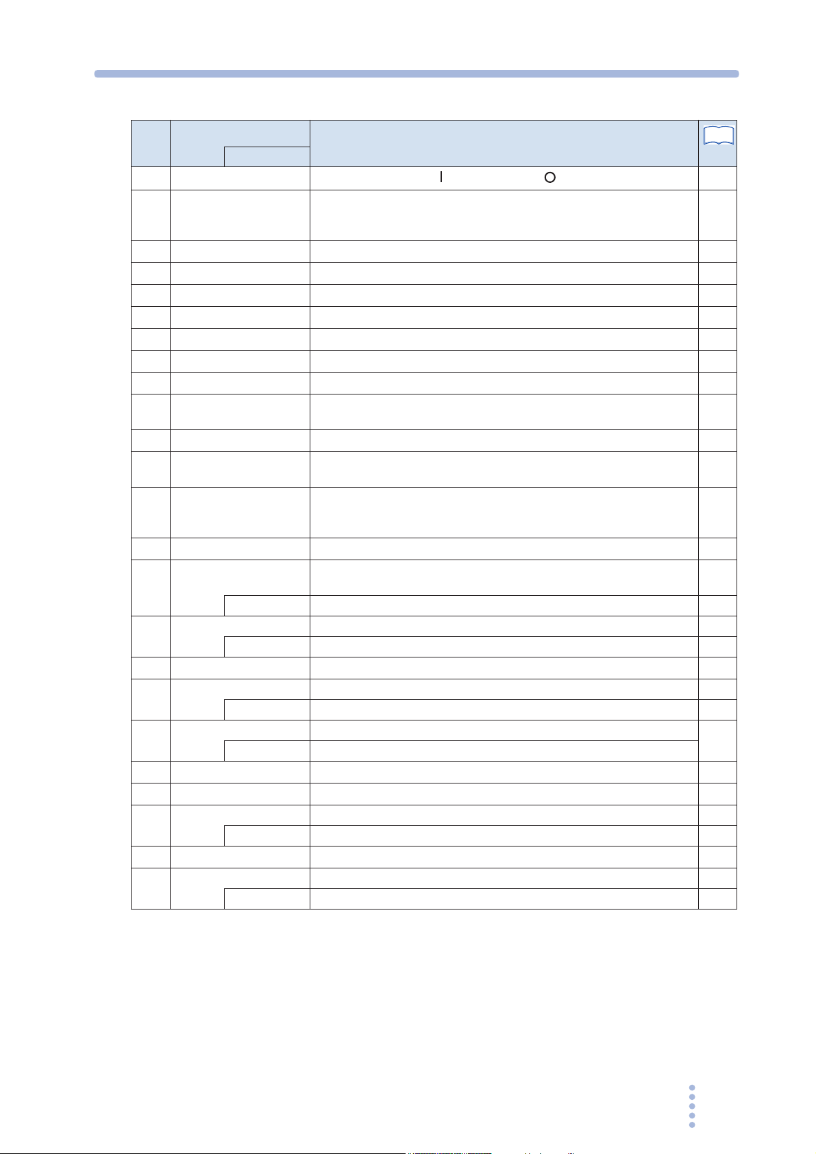
No.
POWER
1
Feet PCR500M: Four locations on the bottom
2
OUTPUT outlet Front panel output
3
Air inlet Air inlet for internal cooling. A dust filter is built in.
4
Handle Handle for transporting
5
CIRCUIT BREAKER Reset button of the circuit breaker.
6
Alarm/overload Illuminates when and alarm or overload occurs.
7
Output mode The selected mode illuminates (AC, DC, or EXT).
8
Upper numeric display Displays voltage or frequency.
9
Lower numeric display Displays current or power. Displays the frequency when the memory
10
Key lock/remote Illuminates when the key is locked or when in remote mode.
11
Rms value, peak value,
12
and average value
Memories A, B, and C The selected memory (A, B, or C) illuminates.
13
Voltage range The selected voltage range (135 V, 270 V, or AUTO) illuminates.
14
I Selects the type of value shown on the lower numeric display (RMS,
15
LIMIT Sets the limit value. The key illuminates when active. 44
16
Rotary knob Changes the settings.
17
STORE Saves to the memory (memories A, B, or C). 46
18
RECALL Recalls from memory.
19
OUTPUT Turns the output on/off.
20
CONFIG Sets the configuration.
21
LOCAL Switches to local mode. 47
22
F Sets the frequency. The key illuminates when active.
23
V Sets the voltage. The key illuminates when active. 38
24
Name
+SHIFT
POWER switch. Push ( ) to turn on; push ( ) to turn off.
PCR1000M / PCR2000M: Four locations on the bottom, four locations
on the side.
is used.
RMS, PEAK, or AVG illuminates according to the type of value shown
on the numeric display.
MEMORY illuminates when saving settings and blinks when recalling
settings.
PEAK, AVG, or W).
RANGE Sets the voltage range. 37
ALM CLR Clears alarms. 48
KEY LOCK Locks the keys 48
ENTER Confirms memory recall or storage.
SHIFT SHIFT key –
AC/DC/EXT Selects the output mode. 36
Description
See
Page
28
–
30
66
–
51
49
36
–
42
48
42
46
37
42
–
46
40
52
39
PCR-M 13
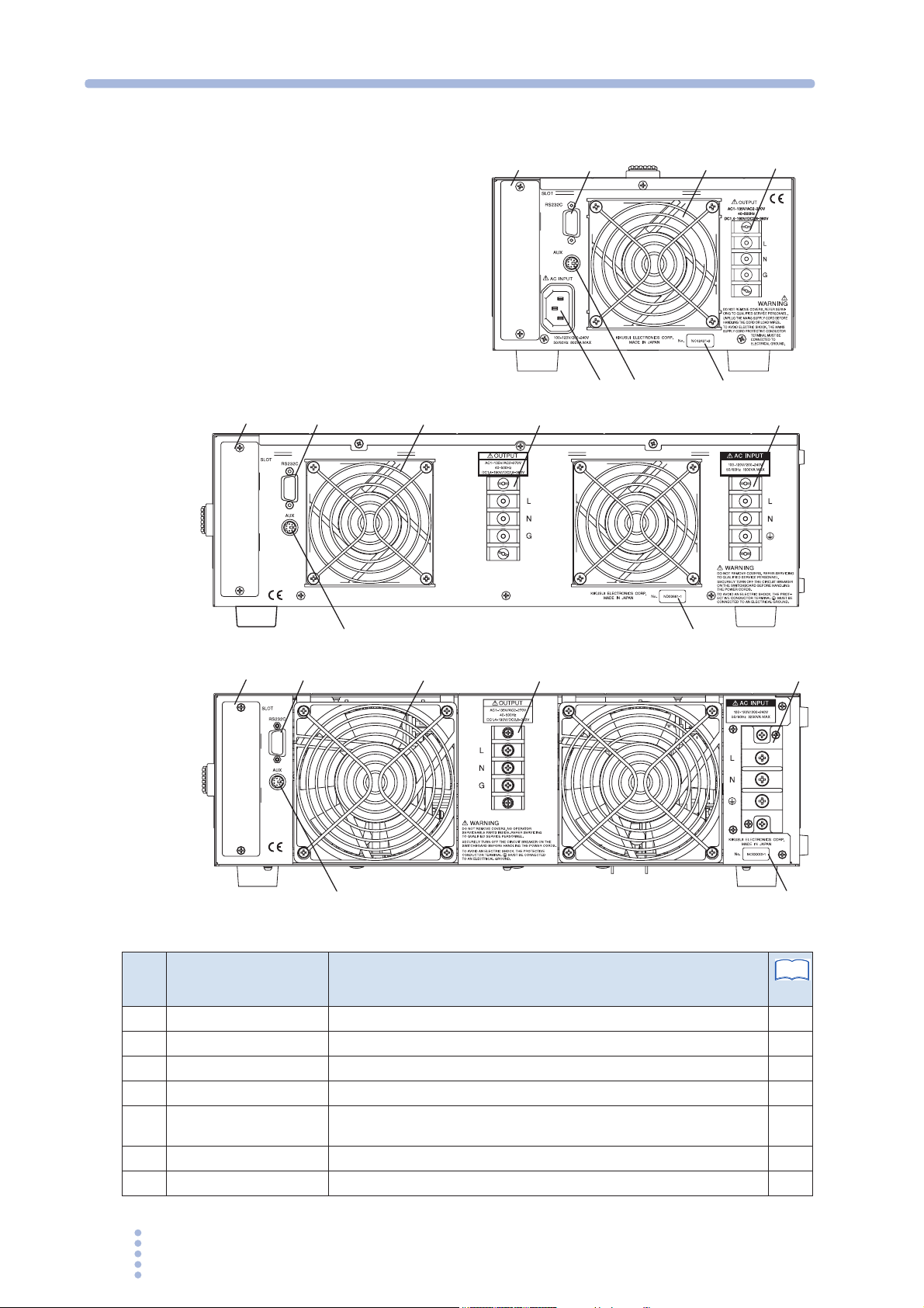
Rear panel
PCR1000M
34
2
1
PCR500M
56
34
2
15
7
6
34
PCR2000M
6
No. Name Description
OUTPUT terminal block Output terminal block with a cover
1
Air outlet Exhaust port for cooling
2
RS232C A connector for RS232C remote control
3
Option slot Installs an option board.
4
AC INPUT PCR500M: AC inlet
5
AUX A connector for functional expansion
6
Serial number Serial number of PCR-M series
7
PCR1000M / PCR2000M: AC input terminal block
7
152
7
See
Page
30
–
75
17
25
–
–
14 PCR-M

1
General Description
This chapter gives a general description and introduces the
features of the PCR-M.

Chapter 1 General Description
1.1 Overview
The PCR-M is a compact AC power supply that inherits the high quality and high
performance features of the PCRthe desktop or by the desk.
It is equipped with the functionality and performance required of a test instrument
for the design, development, and quality assurance of DC/DC converters for devices
and onboard power supplies.
Firmware version of the product to which this manual applies
This manual applies to PCR-Ms with firmware version 1.2x
When making an inquiry about the product, please provide us with the following
information.
See
page 28
• Model (indicated at the top section on the front panel)
• Firmware version
LA/W Series. The PCR-M can be readily used on
Features
• Serial number (indicated at the bottom section on the rear panel)
● Wide range of output voltage and frequency
The output voltage and frequency can be set over a wide range. Nominal voltage
of various countries (single-phase) can be supported. The PCR-M can be used to
test power supplies that are to be placed on airplanes, ships, etc.
● DC output
DC output is possible. The DC voltage can be superimposed on the AC voltage if
the optional interface board is used.
● Compact and light
The reduction in size and weight can be enabled by using a PWM inverter
method.
respect to Kikusui’s linear amplifier type AC power supplies.
● Memory function
Up to three presets can be stored. Presets can be recalled in the middle of the
output operation to test drastic changes in voltage or frequency.
PCR500M is approximately 1/5th in volume and 1/4th in weight with
● Measurement function
Voltage, current, and power of AC and DC output can be monitored. The true
rms value and average value (DC) of the output voltage as well as the true rms
value, peak value, and average value (DC) of the output current can be displayed.
● Maximum peak current
A maximum peak current that is three times the maximum rated current (rms
value) can be output to a capacitor-input rectifying load.
16 PCR-M

1.2 Options
Interface boards
The functions below are expanded depending on the interface board that is installed
in the PCR-M.
• Selection of AC+DC mode in which DC power is superimposed on the AC
power
• Increased number of memory sets from 3 to 10.
■ GPIB interface board (IB21)
This is an interface board used to control the PCR-M with the GPIB.
■ USB interface board (US21)
This is an interface board used to control the PCR-M with the USB.
Chapter 1 General Description
■ Analog interface board (EX04-PCR-M)
This is an interface board used to control the output with external analog signals.
The following functions are expanded.
• The voltage of the output AC waveform (sine wave) is varied according to the
input DC signal
• The input waveform is simplify amplified and output (EXT-DC mode).
(EXT-AC mode).
PCR-M 17
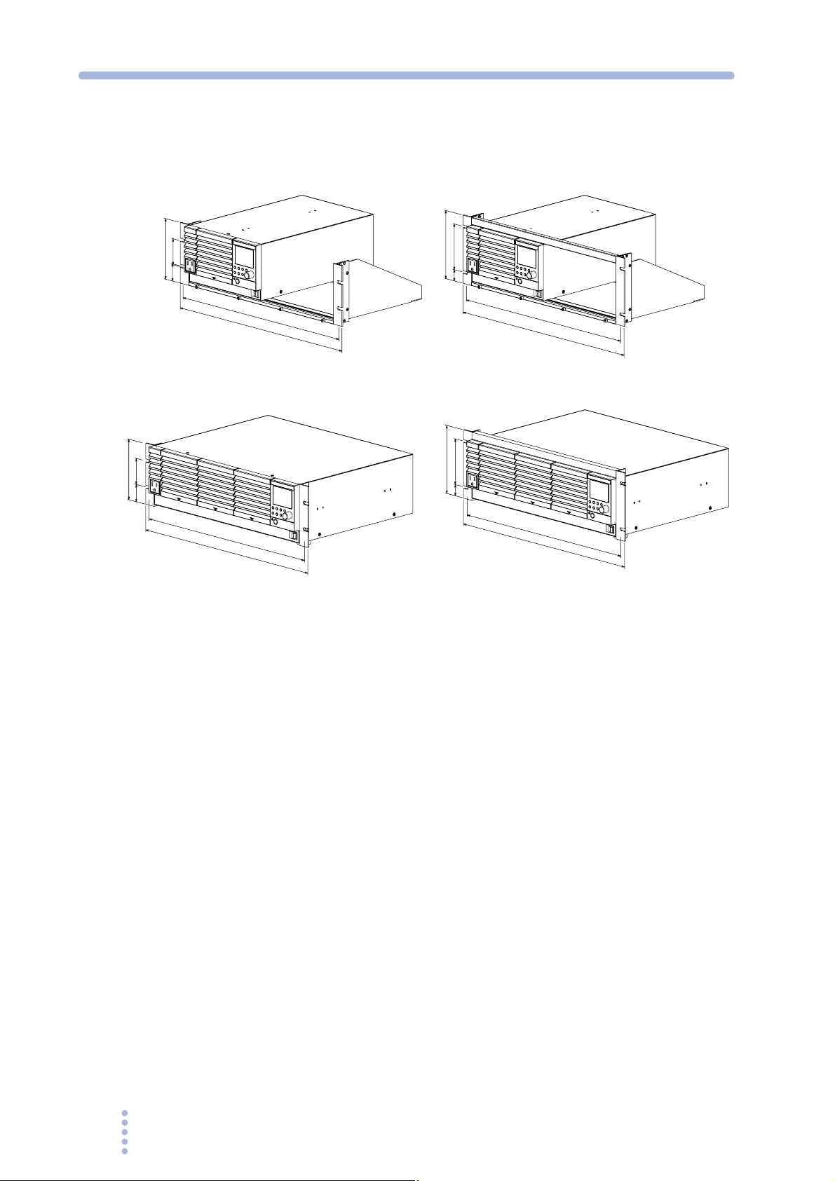
Chapter 1 General Description
Rack mount option
Rack mounting options shown in Fig.1-1 are available.
PCR500M
57(2.24)
132.5(5.22)
149
100
24.5
37.75(1.49)
465(18.31)
482(18.98)
KRA3
Inch rack EIA standard
PCR1000M / PCR2000M (Example : PCR1000M)
57(2.24)
132(5.20)
37.5(1.48)
465(18.31)
478(18.82)
KRB3-TOS
Inch rack EIA standard
Fig.1-1 Rack mount option
46
0
KRA150
480
Milli rack JIS standard
149
100
24.5
46
0
478
KRB150-TOS
Milli rack JIS standard
Unit: mm (inch)
18 PCR-M

2
Installation and Preparation
This chapter describes the procedures from unpacking to
installation.
Chapter 2 Installation and Preparation
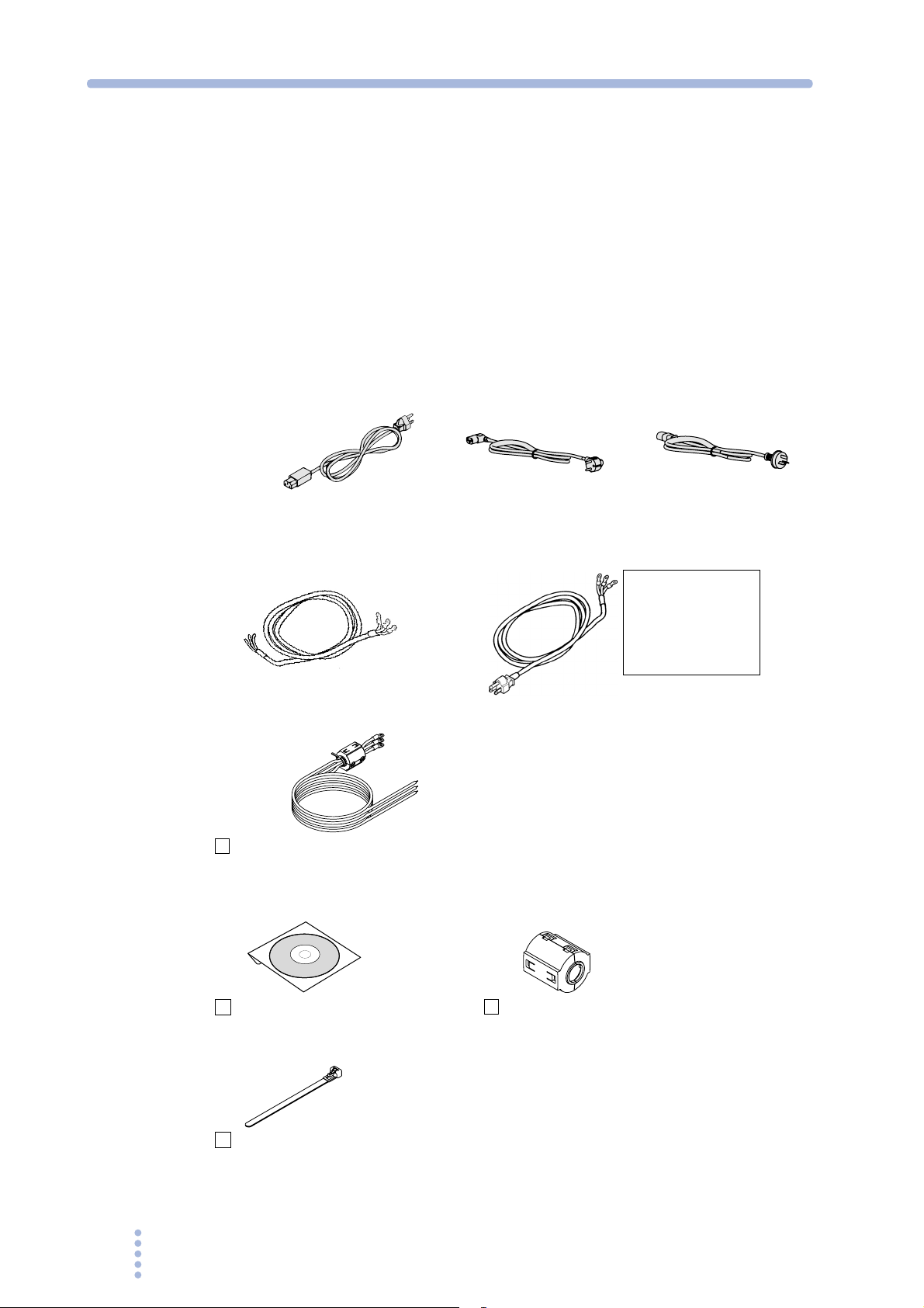
2.1 Checking the Package Contents
When you receive the product, check that all accessories are included and that the
product and accessories have not been damaged during transportation.
If any of the accessories are damaged or missing, contact your Kikusui agent or
distributor.
We recommend that all packing materials be saved, in case the product needs to be
transported at a later date.
Accessories
For PCR500M (1 pc.)
or or
Rated voltage: 125 Vac
PLUG: NEMA5-15
[85-AA-0004] [85-AA-0005]
For PCR1000M (1 pc.)
[85-10-0630]
For PCR2000M (1 set)
Ferrite Core
[96-01-0180]
Power cord
Power cord
The power cord that is provided varies depending on the destination for the product
at the factory-shipment.
[91-87-6140]
Rated voltage: 250 Vac
PLUG: CEE7/7
or
PLUG: NEMA5-15
[91-87-5752]
Rated voltage: 250 Vac
PLUG: GB1002
[85-10-0790]
This power cord with the
plug can be used for the
input voltage of 114 Vac
to 126 Vac. It can not be
used except for those
specified range.
CD-ROM (1 pc.)
[SA-6021]
Cable tie (Only PCR2000M) (1 pc.)
[P4-200-001]
Ferrite Core (Only PCR2000M) (1 pc.)
[96-01-0180]
Fig.2-1 Accessories
20 PCR-M

Chapter 2 Installation and Preparation
2.2 Precautions Concerning Installation Location
Be sure to observe the following precautions when installing the PCR-M.
● Do not use the product in a flammable atmosphere.
To prevent the possibility of explosion or fire, do not use the product near alcohol,
thinner or other combustible materials, or in an atmosphere containing such vapors.
● Avoid locations where the product is exposed to high temperature or
direct sunlight.
Do not install the product near a heater or in areas subject to drastic temperature
changes.
Operating temperature range: 0 °C to 40 °C (32 °F to 104 °F)
Storage temperature range: -10 °C to 60 °C (14 °F to 140 °F)
● Avoid humid environments.
Do not install the product in high-humidity locations--near a boiler, humidifier, or
water supply.
Operating humidity range: 20 %rh to 80 %rh (no condensation)
Storage humidity range: 90 %rh or less (no condensation)
Condensation may occur even within the operating humidity range. In such cases, do
not use the PCR-M until the condensation dries up completely.
● Be sure to use it indoors.
This product is designed for safe indoor use.
● Do not install the product in a corrosive atmosphere.
Do not install the product in a corrosive atmosphere or in environments containing
sulfuric acid mist, etc. This may cause corrosion of various conductors and bad
contacts of connectors inside the power supply leading to malfunction and failure, or
in the worst case, a fire.
● Do not install the product in a dusty location.
Accumulation of dust can lead to electric shock or fire.
● Do not use the product where ventilation is poor.
Secure adequate space around the product so that air can circulate around it.
Allow at least 20 cm of space between the air inlet/outlet and the wall (or obstacles).
● Do not place objects on the PCR-M.
Placing objects on top of the product can cause failures (especially heavy objects).
● Do not install the product on an inclined surface or location subject to
vibrations.
The product may fall or tip over causing damages and injuries.
● Do not use the product in a location where strong magnetic or electric
fields are nearby or a location where large amount of distortion and noise
is present on the input power supply waveform.
The product may malfunction.
● Do not use the foot on the side panel for standing the product in upright
position.
It may cause injury to the operator or the damage to the product when it falls down.
PCR-M 21

Chapter 2 Installation and Preparation
2.3 Precautions to Be Taken When Moving the Product
Note the following points when moving or transporting the product to the
installation location.
● Turn off the POWER switch.
Moving the product while the power is turned on can cause electric shock or
damage to it.
● Remove all wiring.
Moving the product with the cables connected can cause wires to break or
injuries due to the product falling over.
● When transporting the product, be sure to use the original packing materials.
Otherwise, damage may result from vibrations or from the product falling during
transportation.
● Be sure to include this manual.
2.4 Attachment to the Rack Mount Frame
Before assemble the unit to the rack mount frame, remove the handle and the feet.
As for the instruction of mount assembly, please refer to the instruction manual of
KRA series.
Install the suitable support angles applying to the used rack system to support the
instrument.
In case the unit is disassembled from the rack mount, it is recommended that all the
removed parts are kept in the storage.
Once the unit is disassembled from the rack mount, please attach all of the removed
parts to original location of each part.
PCR500M
Cover
Bracket
Handle
M4 flat-head screw (M4×0.7×8)
Foot
Rivet
Screw pin
Fig.2-2 Removing the handle and feet (PCR500M)
22 PCR-M
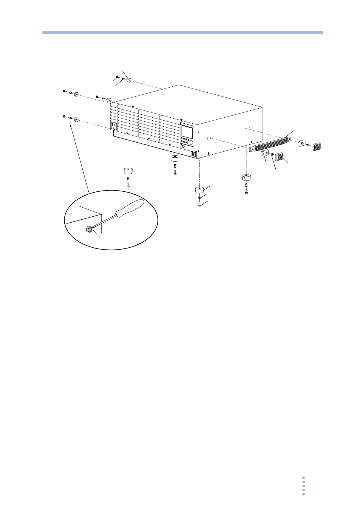
PCR1000M / PCR2000M
Foot
Pin
Rivet
Chapter 2 Installation and Preparation
Handle
Bracket
Foot
Rivet
Screwpin
Usetheflat-head
screwdriverto
removethepin.
Fig.2-3 Removing the handle and feet (Example:
PCR1000M)
Removing the handle and feet
1.
Pull up on the handle cover (two locations).
2.
Unfasten the M4 flat-head screws (two locations) and remove the entire
handle.
Cover
M4flat-headscrew
(M4x0.7x0.8)
3.
While pulling down on each foot on the bottom (four locations), turn the
screw pin, and remove the foot. Remove all four feet.
4.
Unlatch the pin in the foot on the side (four locations) using a flat-head
screwdriver, and remove the foot. Remove all four feet. (PCR1000M /
PCR2000M only)
PCR-M 23
Chapter 2 Installation and Preparation
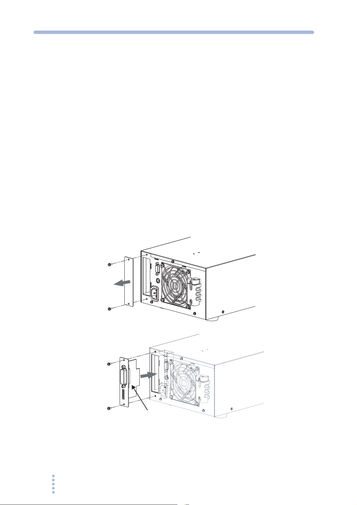
2.5 Attachment of the Optional Interface Board
Install an interface board to the option slot on the rear panel if you wish to control
the PCR-M externally through an interface other than RS232C or control the output
using external analog signals.
1.
Check that the POWER switch is turned off.
2.
Touch the grounded metal to discharge your physical static electricity
3.
Unfasten the screws that are holding the slot cover in place, and
remove the cover from the panel.
4.
Hold the panel section of the board so that the component side of the
printed circuit board is facing right.
5.
Slide the board into the slot so that the connector section of the printed
circuit board is inserted into the connector at the back of the slot.
6.
Push the board all the way in.
7.
Use the screws that were holding the slot cover in place to fix the board
to the panel.
Remove the cover
Insert the board
Component side
Fig.2-4 Attaching the option board
(GPIB interface board example)
The switch at the back of the slot is set to the high side. Do not change the switch
setting.
24 PCR-M

Chapter 2 Installation and Preparation
2.6 Connecting the Power Cord
The power cord provided with the product varies depending on the type. This
product is designed as an equipment of IEC Overvoltage Category II (energy-
consuming equipment supplied from the fixed installation).
WARNING
Possible electric shock.
• This product is an IEC Safety Class I equipment (equipment with a
protective conductor terminal). Be sure to ground (earth) the unit.
• Connect the protective conductor terminal to earth ground.
• PCR500M
Connect the power cord to a properly grounded power outlet.
• PCR1000M / PCR2000M
Make sure to connect the (GND) terminal of the AC INPUT terminal block
to the GND terminal of the switchboard.
PCR500M
The AC power cord that is provided varies depending on the destination for the
product at the factory-shipment.
• Use the supplied power cord to connect to the AC line.
If the supplied power cord cannot be used due to the rated voltage or the plug
shape, have a qualified engineer replace it with an appropriate power cord of
length 3 m or less. If obtaining a power cord is difficult, consult your Kikusui
agent or distributor.
• The power cord with a plug can be used to disconnect the PCR-M from the AC
line in an emergency. Connect the plug to an easily accessible power outlet so
that the plug can be removed from the outlet at any time. Be sure to allow
enough space around the power outlet.
• Do not use the supplied power cord on other instruments.
See
page 72
CAUTION
PCR-M 25
1.
Check that the AC power line complies with the input rating of the PCR-M.
The voltage that can be applied is any of the nominal power supply voltages in the
range of 100 Vac to 120 Vac or 200 Vac to 240 Vac. The frequency is 50 Hz or 60 Hz.
• If the voltage distortion of the AC power line is large, it can lead to
malfunction. The PCR-M cannot be connected to a generator or a similar
device.
2.
Check that the POWER switch is turned off.
3.
Connect the power cord to the AC INPUT inlet on the rear panel.
4.
Insert the power plug to an outlet.
Chapter 2 Installation and Preparation
PCR1000M / PCR2000M
See
page 25
WARNING
CAUTION
When the power cord with the plug is attached to the PCR1000M, see the case of
model
PCR500M.
The power cord attached to the PCR1000M (excluding the cord with plug) and the
PCR2000M can be used either at 100Vac to 120 Vac or 200Vac to 240 Vac of the
input voltage range.
Possible electric shock.
• Turn off the circuit breaker of switchboard before connecting the
cord.
• Do not use the terminal block with the terminal cover removed.
Possible Fire.
• Have a qualified engineer connect the power cord to the switchboard.
• The breaker of switchboard is required to meet following requirement.
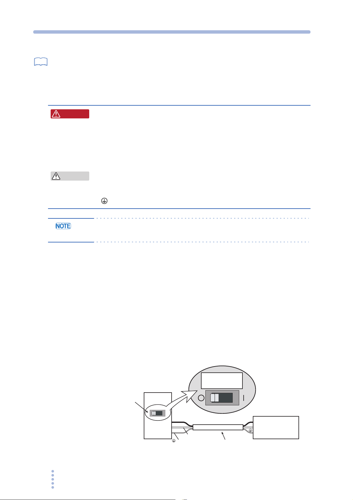
• Inside the product, protective circuits including input fuses are connected
to match the polarity of the input terminal. Make sure the colors of the
wires connected to the corresponding input terminals (L, N, and
(GND)) are correct.
• Turn off the
circuit breaker of switchboard to disconnect the PCR1000M /
PCR2000M from the AC line in an emergency.
■ Circuit breaker of switchboard requirement
• Rated current
PCR1000M: 20 A (The circuit breaker of which the rated current is more than 20
A is disabled for safety.)
PCR2000M: 40 A (The circuit breaker of which the rated current is more than 40
A is disabled for safety.)
• Dedicate the circuit breaker for the PCR1000M / PCR2000M.
• Keep the switchboard easily accessible at any time.
• Require labeling to identify that the circuit breaker is dedicated for the
PCR1000M
ForPCR1000M
exclusiveuse
/ PCR2000M and disconnecting device.
Examplecircuitbreakerlabel
ForPCR1000M
exclusiveuse
20A
Switchboard
(blackorbrown)
L
(whiteofblue)
N
(greenorgreen/yellow)
Suppliedpowercord
L
N
PCR1000M
Fig.2-5 Connecting to the switchboard (Example: PCR1000M)
26 PCR-M

Chapter 2 Installation and Preparation
1.
Check that the AC power supply meets the nominal input rating of the
PCR1000M / PCR2000M.
The voltage that can be applied is any of the nominal power supply voltages in the
range of 100 Vac to 120 Vac or 200 Vac to 240 Vac. The frequency is 50 Hz or 60 Hz.
CAUTION
• If the voltage distortion of the AC power line is large, it can lead to
malfunction. The PCR-M cannot be connected to a generator or a similar
device.
2.
Turn off the POWER switch.
3.
Remove the terminal cover that is attached to the AC INPUT terminal
block.
4.
Securely connect the power cord to match the L, N, and (GND) of the
AC INPUT terminal block.
5.
Put the terminal cover back to the terminal block that you removed in
procedure 3 .
For PCR1000M, use holes on lower side to attach the terminal cover.
6.
Attach crimp terminals to the switchboard end of the power cord.
The switchboard end of the input power cable is not provided with terminals.
For termination, attach a crimp-style terminal to each wire that meets the terminal
screws of the switchboard to be connected, and then securely connect the wires to the
terminal screws. Connection must be performed by qualified personnel.
7.
Turn off the switchboard.
8.
PCR1000M
3
PCR2000M
3
Connect the power cord to match the L, N, and (GND) of the
switchboard.
4
L(black or
brown)
N(white or
blue)
(green or
green/yellow)
4
L(black or
brown)
N(white or
blue)
( green or
green/yellow)
5
Use the
lower holes.
5
Fig.2-6 Connecting to the AC INPUT terminal block
PCR-M 27
Chapter 2 Installation and Preparation
2.7 Turning the Power On
Turning the POWER switch on
See
Fig. 2-7
Turn the power on without the load connected.
1.
Check that the POWER switch is turned off ( ).
2.
Check that nothing is connected to the OUTPUT terminal block on the
rear panel and the OUTPUT outlet on the front panel.
3.
Check that the power cord is correctly connected.
4.
Turn the POWER switch on.
Push the ( ) side of the POWER switch to turn the PCR-M on.
If an odd sound, odd odor, fire, or smoke occurs around or in the PCR-M, remove the
power plug from the outlet or turn off the switchboard.
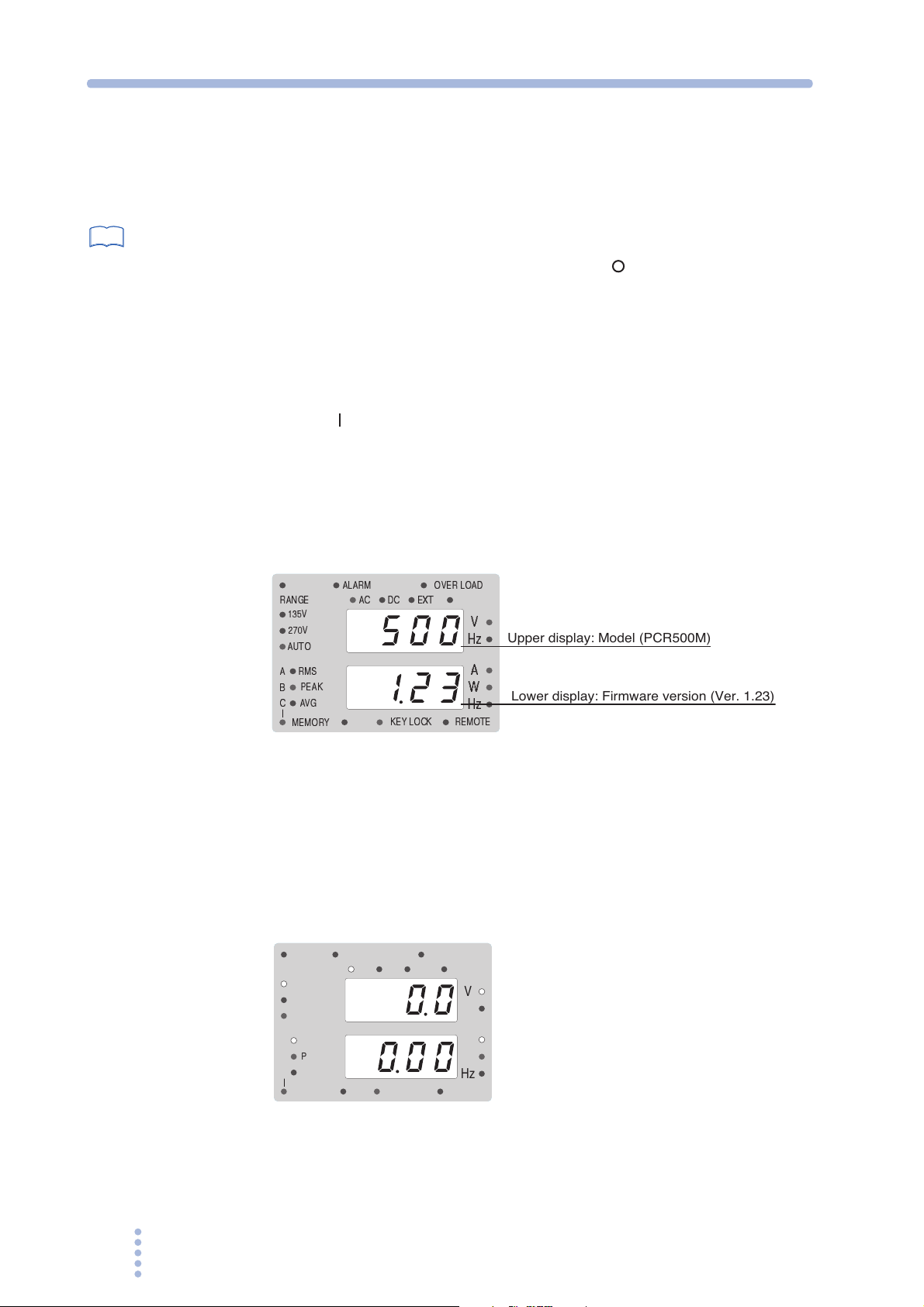
5.
Check the firmware version on the front panel display.
The firmware version as shown in Fig. 2-7 is displayed for few seconds, and
a self-test is carried out. If no error is detected, the measured value display appears.
RANGE
135V
270V
AUTO
A
B
C
MEMORY
RMS
PEAK
AVG
ALARM
DC
AC
EXT
KEY LOCK
OVER LOAD
Hz
Hz
REMOTE
V
Upper display: Model (PCR500M)
A
W
Lower display: Firmware version (Ver. 1.23)
Fig.2-7 Checking the firmware version
(Example: Ver.1.23, PCR500M)
The measured value display appears after displaying the firmware version.
If the POWER switch is turned on for the first time after purchasing the PCR-M, the
PCR-M starts up using factory default settings. For all other cases, the PCR-M starts
up using the settings that existed when the POWER switch was turned off the last
time.
RANGE
135V
270V
AUTO
A
B
C
MEMORY
ALARM
AC
RMS
PEAK
AVG
DC
KEY LOCK
OVER LOAD
EXT
V
Hz
A
W
Hz
REMOTE
Fig.2-8 Measured value display
If the ALARM LED illuminates or an error number is displayed, see section
3.11, “Protection Functions and Alarm Errors.”
28 PCR-M
 Loading...