

Kikusui PCR3000WE2, PCR2000WE, PCR1000WE, PCR6000WE2, PCR6000WE2R User Manual
...
User’s Manual
PCR-WE Series AC Power Supply
PCR1000WE
PCR2000WE
PCR-WE2 Series AC Power Supply
PCR3000WE2
PCR6000WE2/ PCR6000WE2R
PCR12000WE2/ PCR12000WE2R
PCR18000WE2/ PCR18000WE2R
PCR24000WE2/ PCR24000WE2R
PCR30000WE2/ PCR30000WE2R
PCR36000WE2/ PCR36000WE2R
Contents 7
Component Names 10
Installation 16
Basic Functions 37
Advanced Functions 84
Sequence Function 111
External Control 150
Parallel Operation 176
System Settings 186
Maintenance 196
Specifications 199
Appendix 220
Part No. IB032791
Sep 2018

This manual provides an overview of the product and
About Manuals
PDFPDF
PDFPDF
PaperPaper
PDFPDF
PaperPaper
notes on usage. It also explains how to configure it, operate it, perform maintenance on it, and so on. Read this
manual thoroughly before use, and use the product properly.
Intended readers
These manuals are intended for users of this product and
their instructors. The manuals assume that the reader has
knowledge about power supplies.
Manual construction
• User’s manual (this manual)
This document is intended for first-time users of this
product. It provides an overview of the product, notes on
usage, and specifications. It also explains how to connect the product, configure the product, operate the
product, perform maintenance on the product, and so
on.
• Communication Interface Manual
This document contains details about remote control.
The interface manual is written for readers with sufficient
basic knowledge of how to control measuring instruments using a PC.
Trademarks
Microsoft is a registered trademark or trademark of Microsoft Corporation in the United States and/or other countries.
Other company names and product names used in this
manual are generally trademarks or registered trademarks
of the respective companies.
Copyright
Reproduction and reprinting of this operation manual,
whole or partially, without our permission is prohibited.
Both unit specifications and manual contents are subject to
change without notice.
© Copyright 2018 Kikusui Electronics Corporation
• Read This First!
This document is intended for first-time users of the
product. It gives an overview of the product, safety precautions, and so on.
• Quick Reference
This document briefly explains how to use the soft keys.
• Safety Information
This document contains general safety precautions.
Keep them in mind and make sure to observe them.
PDF files are included in the accompanying CD-ROM. You
can view the PDF files using Adobe Reader.
PaperPaper
PDFPDF
PDFPDF
Firmware versions that this manual covers
This manual covers firmware versions 1.2X.
When contacting us about the product, please provide us
with:
The model
The firmware version
The serial number
For information on how to check the model firmware version, and serial number, see “Viewing the firmware ver-
sion” (p.46).
2 User’s Manual PCR-WE/PCR-WE2
• In this manual, the PCR-WE Series AC Power Supply is
Notations Used in This Document
WARNING
CAUTION
Checking the Package Contents
Control panel.
External control
(DIGITAL I/O)
connector
also referred to as the “PCR-WE.” The PCR-WE2 Series
AC Power Supply is also referred to as the “PCR-WE2.”
PCR-WE Series/PCR-WE2 Series is also referred to as
the “PCR-WE/PCR-WE2.”
The PCR6000WE2R, PCR12000WE2R,
PCR18000WE2R, PCR24000WE2R, PCR30000WE2R,
and PCR36000WE2R are also referred to as the “PCRWE2R.”
Single-phase output, single-phase three-wire output,
and three-phase output are also referred to as 1P,
1P3W, and 3W, respectively.
• The term “PC” is used to refer generally to both personal
computers and workstations.
• The screen captures and illustrations used in this text
may differ from the actual items.
• The PCR-WE2R has a regeneration function. Because
the operation and panel diagrams are the same as those
of the PCR6000WE2/PCR12000WE2/PCR18000WE2/
PCR24000WE2/PCR30000WE2/PCR36000WE2, read
the model names in the text as follows:
PCR6000WE2R:PCR6000WE2 → PCR6000WE2R
PCR12000WE2R:PCR12000WE2 → PCR12000WE2R
PCR18000WE2R:PCR18000WE2 → PCR18000WE2R
PCR24000WE2R:PCR24000WE2 → PCR24000WE2R
PCR30000WE2R:PCR30000WE2 → PCR30000WE2R
PCR36000WE2R:PCR36000WE2 → PCR36000WE2R
• The following markings are used in this manual.
Check that all accessories are included and that the main
unit and accessories have not been damaged during transportation.
If the main unit or any of the accessories are damaged or
missing, contact your Kikusui agent or distributor.
We recommend that you save all packing materials, in
case the product needs to be transported at a later date.
Accessories
□ Cable tie (4 pc.) [P4-200-006]
□ External control (DIGITAL I/O) connector (1 pc.)
PCR6000WE2/ PCR12000WE2/ PCR18000WE2/
PCR24000WE2/ PCR30000WE2/ PCR36000WE2
have connectors stored on the back of the control
panel.
Indicates a potentially hazardous situation which, if
ignored, could result in death or serious injury.
Indicates a potentially hazardous situation which, if
ignored, may result in damage to the product or other
property.
Indicates information that you should know.
Indicates a reference manual (CD-ROM) containing
detailed information.
>
This indicates the hierarchy of the items that you select
with the panel keys and function keys. The item to the
left of this symbol indicates a higher level item.
For example, press V > ACVOLT (F1) indicates that you
need to press the V key and then the ACVOLT (F1)
function key.
(SHIFT+key name)
Indicates an operation that requires you to press a key
indicated in blue characters (the lower row of text to the
left of the key) while holding down SHIFT.
□ Heavy object warning label (1 pc.) (excluding the
PCR1000WE)
□ Read This First! (1 copy)
□ Quick Reference (1 sheet)
□ CD-ROM (1 disc)
□ Safety Information (1 copy)
PCR-WE/PCR-WE2 User’s Manual 3
When installing this product, be sure to observe the pre-
Safety Precautions
Precautions When Choosing the Installation Location
Moving the Product
Down
Up
Stopper
PCR6000WE2
PCR12000WE2
PCR24000WE2
PCR30000WE2
PCR36000WE2
Free
Free
Lock
cautions provided in the Safety information manual.
When installing this product, be sure to observe the “Precautions When Choosing the Installation Location” in the
Safety information manual. Items specific to this product
are given below.
• The PCR-WE2R is designed for local regeneration
applications. It cannot be used if the local power consumption is less than the regenerated power.
• When installing this product, be sure to observe the temperature and humidity ranges indicated below.
Operating temperature range: 0 °C to 50 °C (32°F to
122°F)
Operating humidity range: 20 %rh to 80 %rh (no condensation)
• When storing this product, be sure to observe the temperature and humidity ranges indicated below.
Storage temperature range: -10 °C to 60 °C (14 °F to
140 °F)
Storage humidity range: 90 %rh or less (no condensation)
• Allow at least 50 cm of space between the air inlet/outlet
and the wall (or obstacles).
• Fix the product to the floor using L-shaped or other similar brackets (PCR30000WE2, PCR36000WE2 only).
Base hold angles (OP03-KRC) are available as options.
When moving or transporting this product to the installation
location, be sure to observe the “Precautions When
Choosing the Installation Location” in the Safety information manual. Items specific to this product are given below.
• Raise the stopper (PCR18000WE2, PCR24000WE2,
PCR30000WE2, PCR36000WE2 only).
Moving the product without raising the stopper may cause
injuries due to the product falling over.
• Unlock the casters (PCR1000WE, PCR2000WE,
PCR3000WE2 excluded).
• Do not move the product by yourself (PCR30000WE2,
PCR36000WE2 only).
Be sure to have two or more people move the product. Exercise special care when carrying the product over a slope or
across steps.
If you are using a forklift, be sure to slide the forks under the
bottom of the product, check that the product is stable, and
then raise the product.
If you are using a band or similar item to raise the product
with a crane, be sure to slide the band under the bottom of
the product, check that the product is stable, and then raise
the product.
• Do not tip the product on its side or turn it upside down.
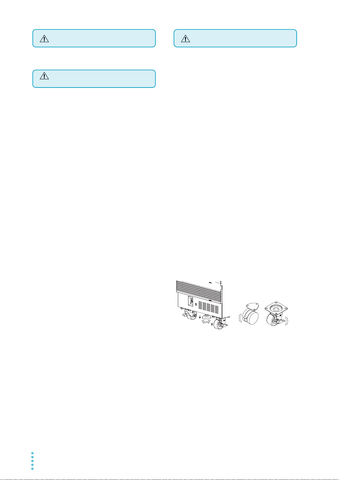
Locking the casters and using the stopper
(PCR1000WE, PCR2000WE, PCR3000WE2
excluded).
This product has casters on its bottom side, so it is easy to
move the product.To ensure that the product is not moved
accidentally while it is being operated, lock the casters with
your foot. For the PCR18000WE2, PCR24000WE2,
PCR30000WE2, and PCR36000WE2, use stoppers to fix
the product in the installation location.
Looking down at the stopper from above, turning the stopper to the left (counterclockwise) raises the stopper, and
turning the stopper to the right (clockwise) lowers the stopper.
PCR18000WE2
Lock
4 User’s Manual PCR-WE/PCR-WE2
The PCR-WE2 consists of three power modules.
Product Overview
U phase
Power module
U phase
Power module
W phase
Power module
W phase
Power module
Pause
V phase
Power module
V phase
Power module
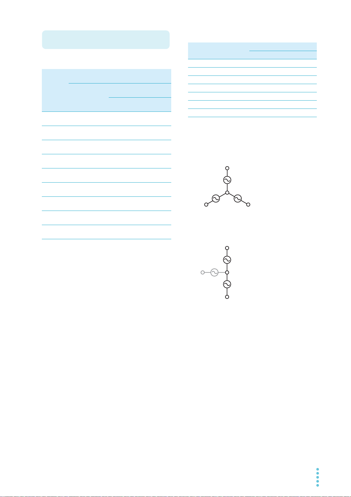
Three-phase output
Single-phase three-wire output
U
U
V
V
W
W
PCR-WE/PCR-WE2 lineup
Model Rated output
capacity
1P output
1P3W
output
3P output
PCR
1kVA — 10A 5A — —
1000WE
PCR
2 kVA — 20 A 10 A — —
2000WE
PCR
3 kVA 2 kVA 30 A 15 A 10 A 5 A
3000WE2
PCR
6 kVA 4 kVA 60 A 30 A 20 A 10 A
6000WE2
PCR
12 kVA 8 kVA 120 A 60 A 40 A 20 A
12000WE2
PCR
18 kVA 12 kVA 180 A 90 A 60 A 30 A
18000WE2
PCR
24 kVA 16 kVA 240 A 120 A 80 A 40 A
24000WE2
PCR
30 kVA 20 kVA 300 A 150 A 100 A 50 A
30000WE2
PCR
36 kVA 24 kVA 360 A 180 A 120 A 60 A
36000WE2
Maximum output current
1P output 1P3W output
100 V
output
200 V
output
3P output
100 V
output
200 V
output
Model 1P out-
put
1P3W / 3P output
U phase V phase W phase
PCR3000WE2 3 kVA 1 kVA 1 kVA 1 kVA
PCR6000WE2 6 kVA 2 kVA 2 kVA 2 kVA
PCR12000WE2 12 kVA 4 kVA 4 kVA 4 kVA
PCR18000WE2 18 kVA 6 kVA 6 kVA 6 kVA
PCR24000WE2 24 kVA 8 kVA 8 kVA 8 kVA
PCR30000WE2 30 kVA 10 kVA 10 kVA 10 kVA
PCR36000WE2 36 kVA 12 kVA 12 kVA 12 kVA
During single-phase output and three-phase output, all
power modules are used.
During single-phase three-wire output, the W-phase power
module is not used.
PCR-WE/PCR-WE2 User’s Manual 5

Features
The PCR-WE/PCR-WE2 is equipped with the following
functions.
Switchable between single-phase output, singlephase three-wire output, and three-phase output
(PCR-WE2 only)
Three types of output are available on a single unit.
Power regeneration function (PCR-WE2R only)
Load power can be regenerated on the AC line. In a typical inverter system, unconsumed power is regenerated
on the AC line. If you use the PCR-WE2R as a power
system simulator, you do not need a regenerative load.
This helps to suppress the level of exhaust heat and
saves energy.
Various power supply simulations
Power line abnormalities such as voltage dips and short
power interruptions can be simulated. This is a basic
function for power-supply-environment testing.
Various measurements
The rms voltage and current, the peak voltage and current, the active power, apparent power, and power factor
of the output can be measured. Harmonic analysis (0th
to 50th) can be performed on the output voltage and current.
DC output
DC output and AC+DC output are possible in addition to
AC output. This makes it possible to use the PCR-WE in
a wide variety of fields, such as chemistry and physics.
Sequence function
The output voltage, frequency, and waveform can be
changed over time. Power-supply-environment testing
can be automated.
In addition to the AC output sequences, DC output and
AC+DC output sequences are also available. A variety
of standard tests can also be performed.
Sensing function and regulation adjustment function
Even if the load device is at a remote location, the PCRWE/PCR-WE2 can stabilize the voltage across the load
by correcting for voltage drops.
There are two types of sensing: hard sensing and soft
sensing. The different types of sensing are used
depending on the load conditions and how you will use
the PCR-WE.
Output current control
The current limit function can be used to limit the output
current (rms) to a fixed value to perform continuous
operation. Continuity tests on electrical equipment (such
as switchboards, breakers, and wiring devices) can be
performed under stable conditions.
Power management function (power conservation
function)
A sleep function, which turns the power modules off to
reduce power consumption when output is not generated for the specified length of time, and a power-saving
function, which operates the power modules at the bare
minimum settings as required by the supply load, are
available.
Memory function
Up to 3 entries of output frequency, voltage (AC and
DC), and waveform bank settings can be saved to the
internal preset memory.
Up to 10 entries of panel settings can be saved to the
internal setup memory.
The internal memory, panel settings, power line abnormality simulations, sequence data, and waveform bank
data can be saved to a USB memory device.
External communications
The PCR-WE/PCR-WE2 can be controlled remotely
through its USB, LAN, and RS232C interfaces. If an
optional interface board is used, the PCR-WE Series
can be controlled remotely through a GPIB interface.
External analog signal control
The output can be controlled using external analog signals.
6 User’s Manual PCR-WE/PCR-WE2

Contents
About Manuals ...................................................2
Notations Used in This Document......................3
Checking the Package Contents ........................3
Safety Precautions .............................................4
Precautions When Choosing
the Installation Location......................................4
Moving the Product ............................................4
Product Overview ...............................................5
Component Names ..........................................10
Installation
Connecting the Power Cord .............................16
Connecting the PCR1000WE/PCR2000WE/
PCR3000WE2 ......................................................19
Connecting the PCR6000WE2/PCR12000WE2...20
Connecting the PCR18000WE2/PCR24000WE2/
PCR30000WE2/PCR36000WE2..........................22
Turning the Power On ......................................24
Preventing the shutdown function from activating 24
Turning the POWER switch on............................. 25
Setting the condition that the product will be in when
the POWER switch is turned on ...........................26
Turning the POWER switch off............................. 26
Connecting the Load ........................................27
Connecting to the OUTPUT terminal block ..........28
Connecting the PCR1000WE/PCR2000WE.........29
Connecting the PCR3000WE2 .............................30
Connecting the PCR6000WE2/PCR12000WE2...32
Connecting the PCR18000WE2/PCR24000WE2/
PCR30000WE2/PCR36000WE2..........................34
Basic Functions
Panel Operation Basics....................................37
Control panel ........................................................37
Parts of the screen ...............................................39
Explanation of function keys in this manual.......... 40
Home position....................................................... 40
Canceling settings ................................................40
Waiting for confirmation ........................................ 40
Busy status ...........................................................41
Returning the product to the factory default settings
41
Switching from remote mode to local mode .........41
Displaying single-phase three-wire output and three-
phase output (PCR-WE2 only) ............................. 42
Specifying values ................................................. 44
Adjusting the screen brightness ........................... 45
Viewing the firmware version ............................... 46
Locking panel operations (key lock) ..................... 46
Selecting the Output Method............................47
Setting the Output Voltage...............................48
Setting the output voltage range ..........................48
About setting the output voltage........................... 49
Output voltage setup procedure for single-phase out-
put ........................................................................ 51
Output voltage setup procedure for single-phase
three-wire output .................................................. 51
Output voltage setup procedure for three-phase out-
put ........................................................................ 53
Setting the voltage offset...................................... 54
Setting the Frequency ......................................55
Turning the Output On/Off................................56
Impedance when the output is off ........................ 57
Voltage surge suppression when the output is turned
off ......................................................................... 58
Output on/off phase control.................................. 59
AC coupling .......................................................... 60
Measurement Display ......................................61
Displaying the voltage .......................................... 61
Load level meter................................................... 63
Displaying the current, power, and power factor .. 64
Limit Function and Protection Function............66
Setting Limits....................................................67
Upper and lower voltage limits ............................. 67
Upper and lower frequency limits ......................... 68
Current limit and peak current limits..................... 68
Using Protection Functions ..............................72
Using the Memory ............................................74
Items that can be saved ....................................... 74
Using internal preset memory .............................. 75
Setting the date and time (time zone) .................. 77
Using the internal setup memory.......................... 78
Using a USB memory device ............................... 79
Advanced Functions
Using the Sync Function ..................................84
Using the Compensation (Voltage compensation)
Function ...........................................................86
PCR-WE/PCR-WE2 User’s Manual 7

Wiring the hard sensing and soft sensing functions ..
88
Wiring the regulation adjustment function .............91
Compensation function setup procedure ..............92
Ending the use of the compensation function .......95
Using Power Line Abnormality Simulations..... 96
Power line abnormality simulation setup procedure..
98
Executing and stopping power line abnormality simu-
lations....................................................................99
Using the Harmonic Analysis Function.......... 100
Generating Special Waveforms (Waveform bank)
101
Setting the waveform bank..................................102
Generating special waveforms ............................103
Setting the Output Impedance....................... 104
Configuring Soft Start and Soft Stop ............. 105
Configuring soft start ...........................................105
Configuring soft stop ...........................................106
Selecting the Response................................. 107
Using the Power Management Functions...... 108
Sleep function .....................................................108
Power-saving function .........................................109
Power module management function..................110
Switching steps at specific phase angles............136
Suddenly changing the phase.............................139
Single-phase three-wire output and three-phase out-
put basics............................................................141
Phase setting for multi-phase output ..................142
Phase sweep ......................................................146
Line voltage dip...................................................148
External Control
Control Using Analog Signals.........................151
ANALOG IN connector pin arrangement ............152
Selecting the parameter to control ......................153
Amplifying the input waveform (EXTDC mode) ..154
Varying the output voltage or frequency using DC sig-
nals (VPROG mode) ...........................................157
Control Using Digital Signals..........................161
DIGITAL I/O connector pin arrangement and map-
ping .....................................................................162
Controlling the PCR-WE through external contacts ..
165
Monitoring the operation status...........................170
Selectable I/O .....................................................173
Selectable signals when INP.SIG is selected .....175
Selectable signals when OUTP.SIG is selected .175
Sequence Function
Sequence Overview ...................................... 111
Editing Steps ................................................. 116
Common items ....................................................116
[1] Frequency and AC voltage.............................117
[2] Execution time, waveform bank .....................118
[3] DC voltage, output .........................................119
[4] Status output, trigger output, trigger input (pause)
120
[5] Jump function.................................................122
[6] Starting phase angle, ending phase angle, sud-
den phase change...............................................123
[7] Output impedance (for single-phase output) ..124
[7] Output impedance (for single-phase three-wire
output and three-phase output, resistance compo-
nent) ....................................................................124
[8] Output impedance (for single-phase three-wire
output and three-phase output, reactance compo-
nent) ....................................................................124
[9] Phase difference for three-phase output ........125
Setting Sequence Conditions ........................ 127
Executing, Pausing, and Stopping Sequences....
128
Sequence Creation Tutorial........................... 129
Sequence creation basics ...................................131
Voltage sweep and frequency sweep .................134
Parallel Operation
Configuring the Master and Slave Units.........177
Installation and Connection............................178
Installation...........................................................178
Connecting PCR-WEs together ..........................178
Turning the Power On and Checking the Opera-
tion..................................................................182
Connecting the OUTPUT terminal block and relay
terminals .............................................................182
Turning the power on ..........................................183
Operation Check .................................................183
Connecting the Load ......................................184
Ending parallel operation................................185
System Settings
Setting the Watchdog Protection (WDP) ........186
Displaying/Changing the Interface Settings ...187
Controlling the PCR-WE/WE2 from a PC ...........187
Displaying SCPI Errors...................................188
Factory Default Settings and Reset Settings..189
Factory default settings.......................................190
8 User’s Manual PCR-WE/PCR-WE2

Updating .........................................................195
Maintenance
Cleaning the Dust Filter ..................................196
Backup Battery Replacement .........................198
Calibration ......................................................198
Specifications
Main Unit Specifications .................................199
Input (AC rms) ....................................................200
Output.................................................................202
Output voltage stability (phase voltage) .............203
Measurement...................................................... 204
Limit values and protection functions .................205
Power line abnormality simulations .................... 206
Sequence operations..........................................206
Special waveform output ....................................206
Output impedance setting...................................207
Output on/off phase setting ................................207
Communication interface.................................... 208
Signal I/O............................................................209
Parallel operation (PCR1000WE/ PCR2000WE/
PCR3000WE2 excluded)....................................213
Memory...............................................................213
Sync function ...................................................... 213
Compensation function.......................................213
Response selection function...............................214
Ecological function..............................................214
Soft start and soft stop functions ........................214
LIN, DSI connection I/O......................................214
General...............................................................215
Rated output current characteristics (derating) .. 216
Outline Drawing..............................................217
GPIB interface board (IB07-PCR-WE) ............... 232
Base hold angles (OP03-KRC) .......................... 233
Parallel operation cables (PC01-PCR-WE, LC01-
PCR-LE) ............................................................. 233
Troubleshooting .............................................234
Alarms and Trouble ........................................237
Overview ............................................................ 237
Remedy .............................................................. 238
Error Messages..............................................240
Index ..............................................................242
Appendix
Terminology....................................................220
Power Regeneration Function (PCR-WE2R only)
223
Output and Load.............................................224
Rated output current for AC output..................... 224
AC output voltage frequency response ..............226
Frequency response for analog input ................. 226
Options ...........................................................227
Input power cords ............................................... 227
External Control Connector ................................ 228
Rack Mount Brackets .........................................228
PCR-WE/PCR-WE2 User’s Manual 9
Component Names
1
2
5
PCR6000WE2
PCR12000WE2
PCR18000WE2
PCR24000WE2
PCR30000WE2
PCR36000WE2
(PCR6000WE2 example)
4
638
6
7
8
43
1
2
5
PCR1000WE
PCR2000WE
PCR3000WE2
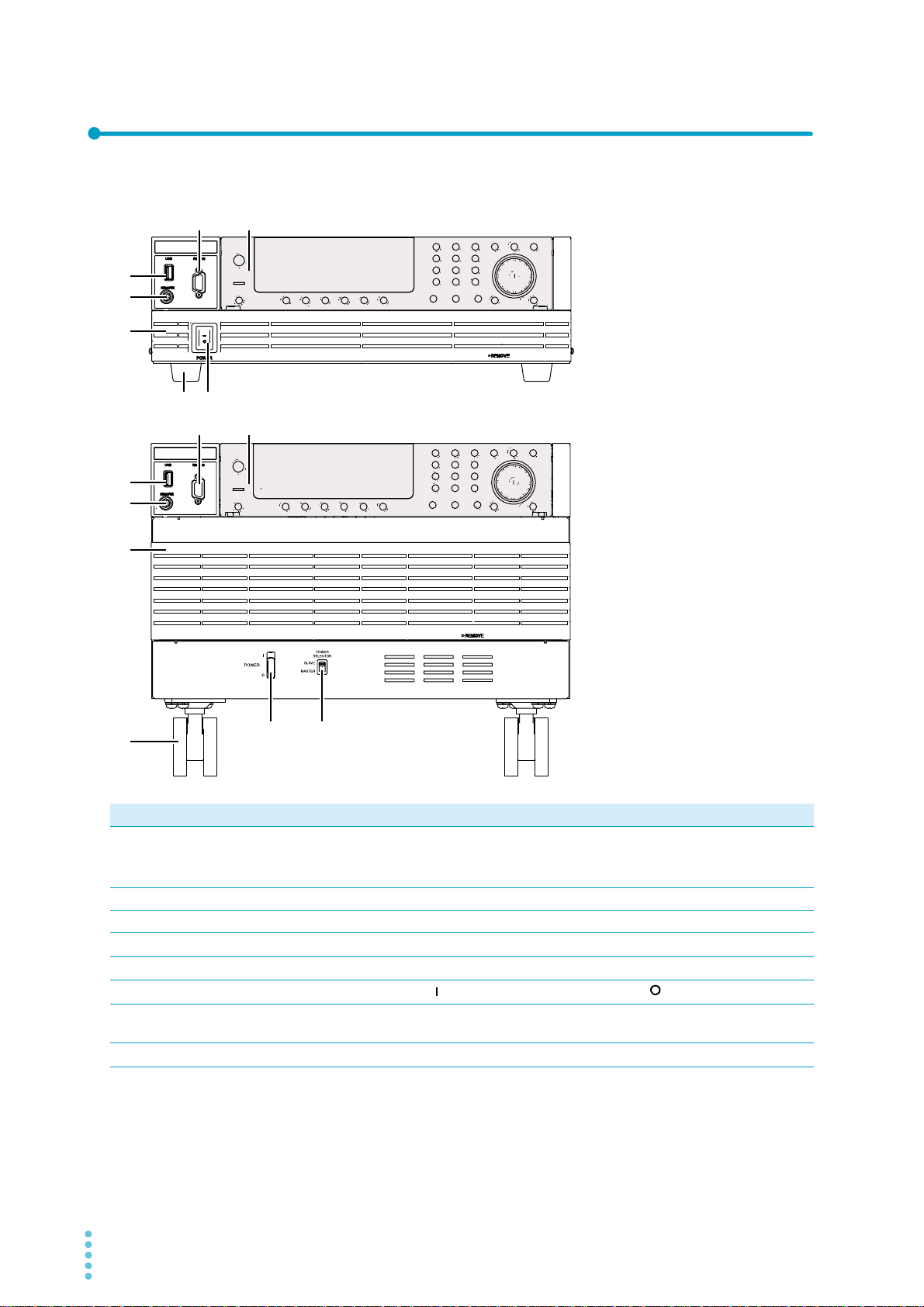
Front panel
No. Name Function See
USB port (host) Connects to an external keyboard.
1
Saves to setup memory.
Used for updating.
REMOTE connector Connector for the optional line impedance network or dip simulator.
2
RS232C port RS232C port for remote control. —
3
Control panel Operation panel and display.
4
Power module air inlet Inlet holes for cooling. —
5
POWER switch
6
POWER SELECTOR
7
switch
Caster and leg 4 locations.
8
Flip the switch to the side to turn the power on and to the side to turn it off.
Power on/off sync switch for parallel operation.
p.79
p.195
p.11
p.24
p.180
p.4
10 User’s Manual PCR-WE/PCR-WE2

Control panel
1
8
9 10 11 12 1413 15 1616
2 3 4 5 6 7
No. Name Function See
OUTPUT Turn the output on and off.
1
Display Displays the settings, measured values, and other information.
2
Numeric keypad Enters values directly.
3
CLR key Clears the input entered with the numeric keypad.
ON PHASE key Sets the output-on phase.
RANGE key Changes the output voltage range.
SYNC key Sets the sync function.
OFF PHASE key Sets the output-off phase.
KEYLOCK key Locks or unlocks the keys.
RESET key Resets the product.
SLEEP key Sets the sleep function.
LOCAL key Switches to local mode from remote mode.
+/- key Changes the voltage polarity of the DC output.
DIGIT key Moves to the left digit when setting a value.
ALM CLR key Clears the alarm.
F key Sets the frequency.
4
PHASE key Switches the displayed phase during multi-phase operation. This is not available
on the PCR1000WE or PCR2000WE.
I key Set the current parameters.
5
I/P/S/λ-MEAS key Switches between current, power, and power factor displays.
V key Sets voltage parameters.
6
V-MEAS key Switches the voltage display.
Rotary knob Rotary knob.
7
ESC key Returns to the previous level or cancels operations.
8
SLEEP LED Blinks in sleep mode.
9
Function keys Executes the function shown above the keys.
10
MEMORY key Saves and recalls from memory.
11
OTHER key Sets advanced operations. —
SHIFT key Enables the functions that are written in blue characters in the bottom row to the
12
ENT key Confirms the settings.
13
SIM key Sets the power line abnormality simulation.
14
SEQ key Sets the sequence operation.
OPR MODE key Sets the operation. —
15
CONFIG key Sets CONFIG parameters. —
Control panel
16
detachment button
left of each key.
Detaches the control panel (two locations).
p.56
p.61
p.44
p.59
p.48
p.84
p.59
p.46
p.189
p.108
p.41
p.44
p.45
p.72
p.55
p.42
p.68
p.64
p.48
p.61
p.44
p.40
p.108
p.39
p.74
p.3
p.40
p.96
p.111
p.37
PCR-WE/PCR-WE2 User’s Manual 11
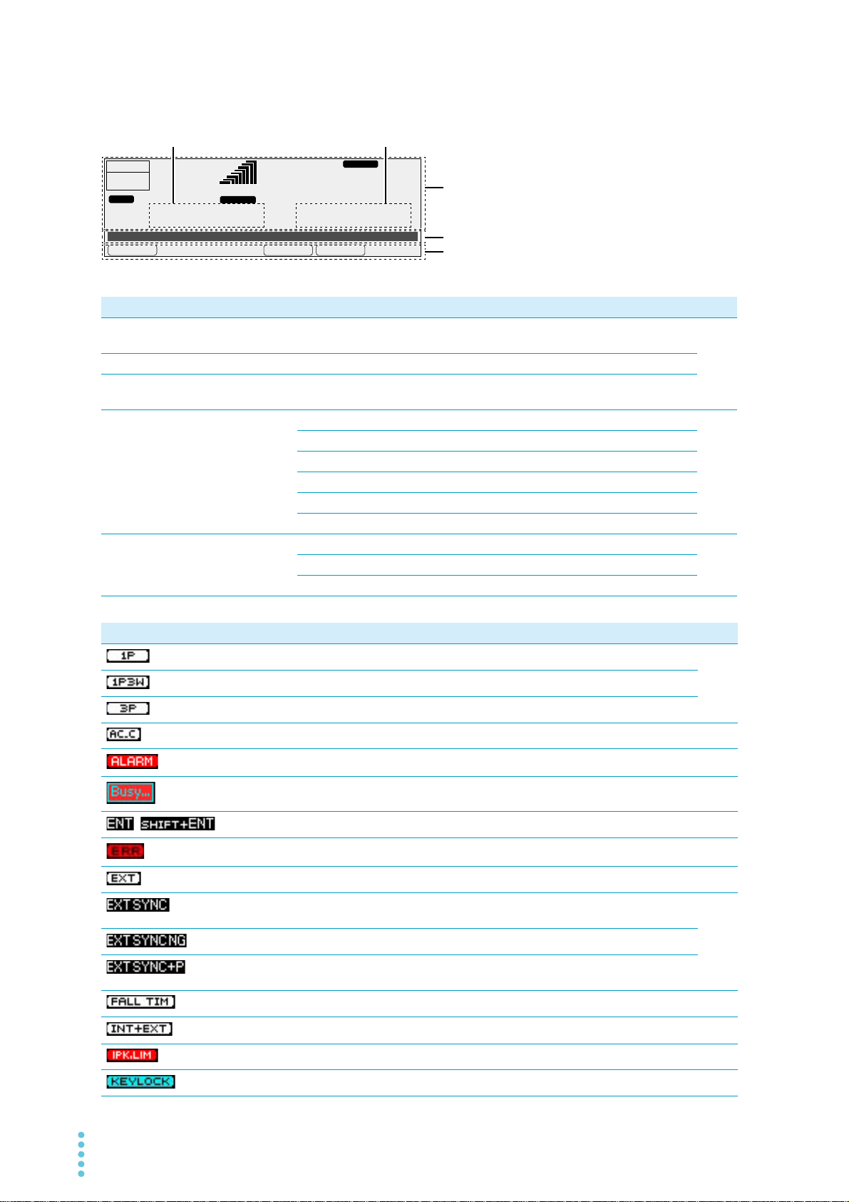
Display and Icons
FMINFMAXFREQ
Freq 50.00Hz
6.87
A
28.1
V
rms rms
LOAD
99.00
Hz
RANGE
L
OUTPUT
OFF
RESP.M
1P
45
1
2
3
No. Name Function See
Status, measured-value, and setting dis-
1
play area
Entry area Area for entering various values and system settings.
2
Function key name area Displays the present functions above the function keys (F1 to
3
Current, power, or power
4
factor display
Voltage display V rms Displays the rms voltage
5
A rms Displays the rms current
A pk Displays the peak current
A dc Displays the average current
W/ kW Displays the power
VA Displays the apparent power
λ Displays the power factor
V pk Displays the peak voltage
V dc Displays the average voltage
Displays the product’s present status, measured values, and
settings.
F6).
p.39
p.64
p.61
icons Description See
Single-phase output
Single-phase three-wire output
Three-phase output
AC coupling on
Alarm generation
Key operation is not possible while internal processing is in progress.
Waiting for confirmation (blinking)
There is an SCPI error.
Amplifies the input waveform using an external signal.
Lights when the external sync function is in use. Blinks until synchronization is established.
Unable to sync to the external sync input signal.
Lights when the external sync function is in use (with the delay phase angle set). Blinks
until synchronization is established.
Soft stop on
Amplifies the input waveform using the internal signal and external signal.
p.47
p.60
p.72
p.41
p.40
p.188
p.154
p.84
p.106
p.154
Peak current limit activated
Keys locked
12 User’s Manual PCR-WE/PCR-WE2
p.69
p.46
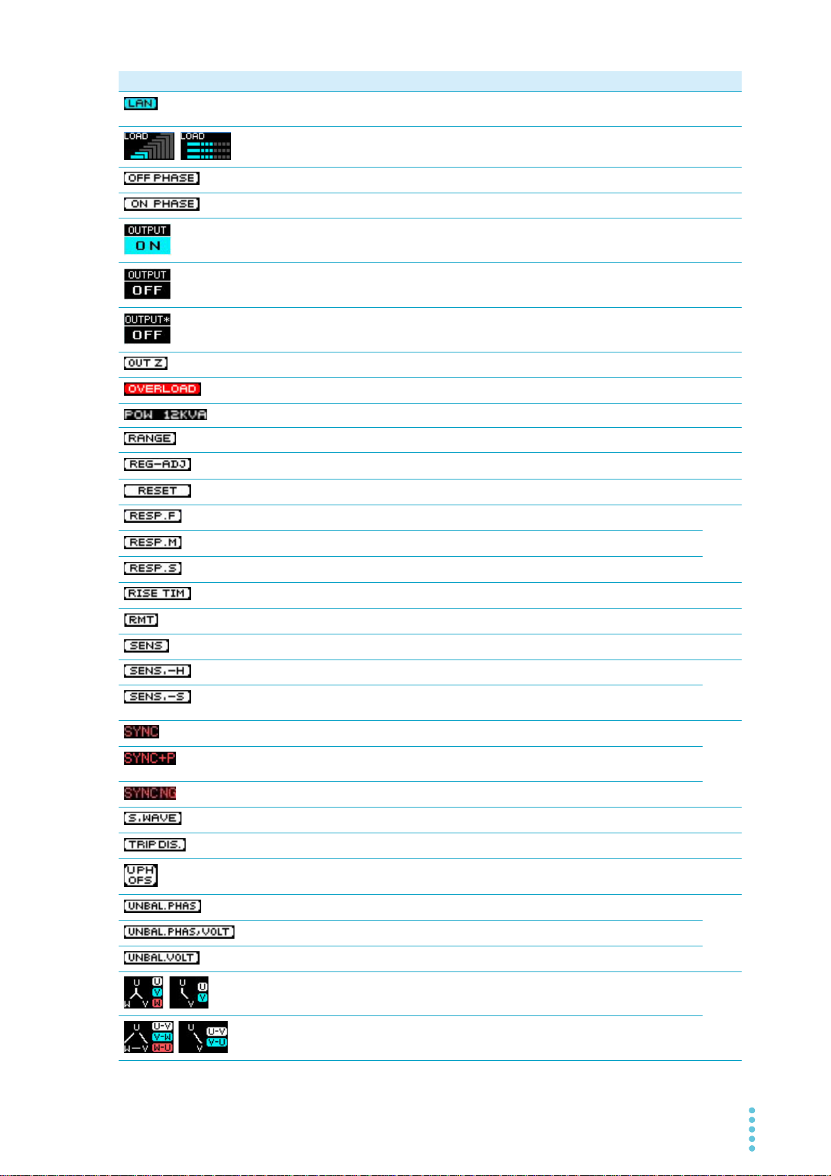
icons Description See
LAN status, red: not connected, orange: connecting, green: communication possible,
—
blinking: identify status
Load level meter
p.63
Output-off phase setting
Output-on phase setting
Output on
Output off
“OFF” blinks when soft stop is in use.
Output off, voltage surge suppression function on
Output impedance setting
Overload occurrence
Power save mode
Output voltage range
Compensation: regulation adjustment
Waiting for reset confirmation or reset in progress
Response: High speed (FAST)
Response: Normal speed (MEDIUM)
Response: High stability (SLOW)
p.59
p.59
p.56
p.56
p.105
p.58
p.104
p.70
p.109
p.48
p.86
p.189
p.107
The soft start function is turned on.
Remote mode
Soft sensing control error
Compensation: hard sensing
Compensation: soft sensing (displayed in red when compensation cannot be completed)
Lights when the sync function is in use. Blinks until synchronization is established.
Lights when the sync function is in use (with the delay phase angle set). Blinks until
synchronization is established.
Lights when synchronization cannot be established with the input power supply.
Non-zero waveform bank number
The action taken when the current limit is exceeded is set to trip (output not turned off).
Sequence ended with the U phase offset
Unbalanced phase difference
Unbalanced phase difference and voltage
Unbalanced voltage
All phase (phase voltage) display for three-phase output or single-phase three-wire output
p.105
p.41
p.86
p.86
p.84
p.101
p.70
p.53
p.42
p.42
All phase (line voltage) display for three-phase output or single-phase three-wire output
PCR-WE/PCR-WE2 User’s Manual 13
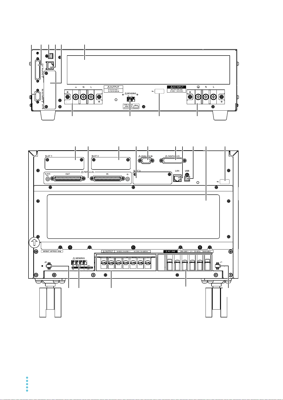
Rear Panel
2 13 14 1
2
1
1316 15
46 53
8 9 1011 12 14
5 1234 67
PCR1000WE/ PCR2000WE/ PCR3000WE2 (PCR1000WE example)
PCR6000WE2/ PCR12000WE2 (PCR6000WE2 example)
14 User’s Manual PCR-WE/PCR-WE2
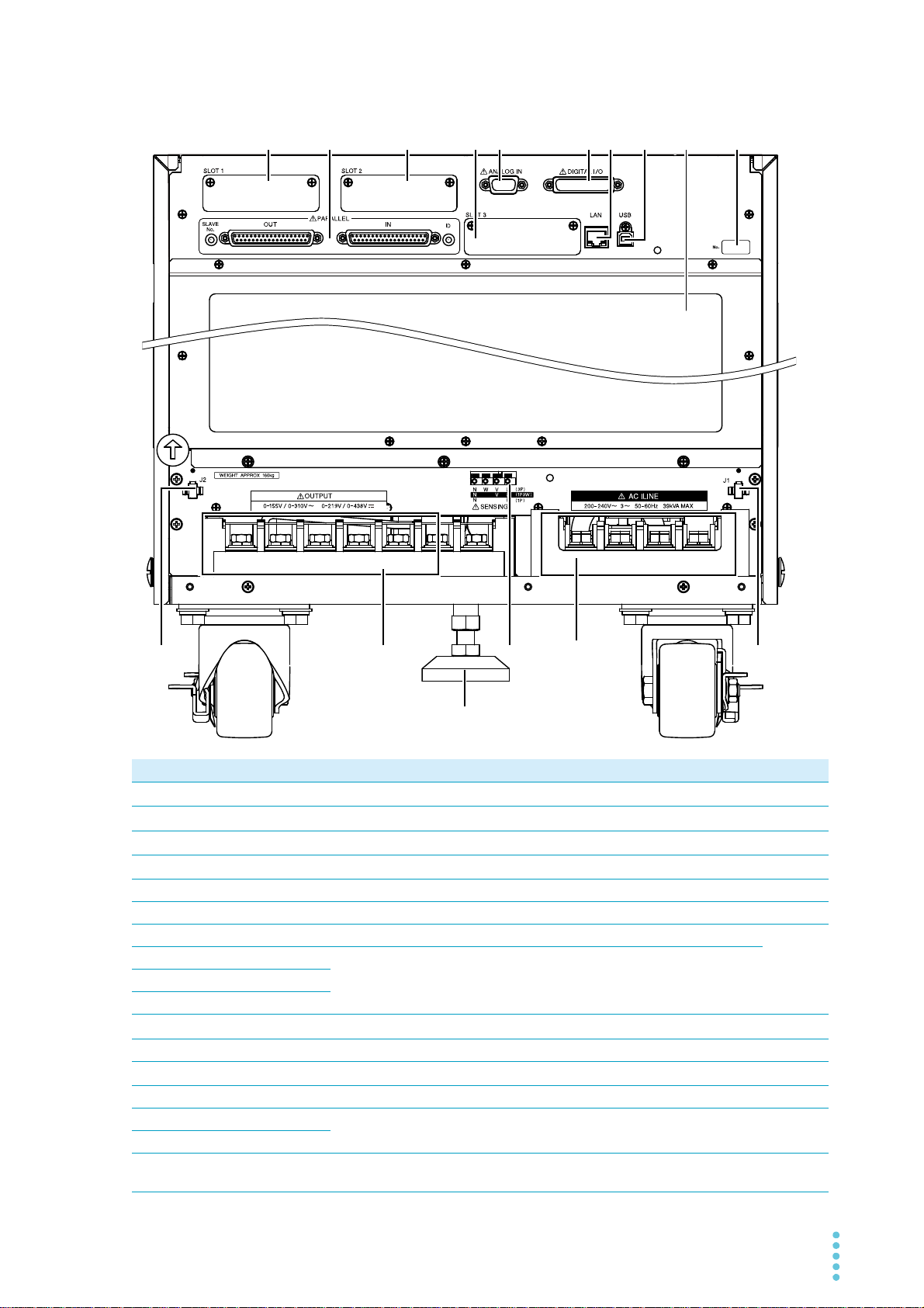
17
2
1
1316
15
46 53
8 9 1011 12 14
PCR18000WE2/ PCR24000WE2/
PCR30000WE2/ PCR36000WE2 (PCR30000WE2 example)
No. Name Function See
AC INPUT terminal block Power inlet with a cover.
1
OUTPUT terminal block Output terminal block with a cover
2
ANALOG IN connector Analog control connector
3
DIGITAL I/O connector Digital control connector.
4
USB port (device) USB port for remote control. —
5
LAN port LAN port for remote control. —
6
SLOT Expansion slot (PCR1000WE, PCR2000WE, PCR3000WE2 only) —
7
SLOT1 Expansion slot (PCR-WE2 (excluding PCR3000WE2) only)
8
SLOT2
9
SLOT3
10
PARALLEL connector Parallel operation connector (PCR-WE2 (excluding PCR3000WE2) only)
11
Power module air outlet Vent for cooling the <series name>. —
12
SENSING terminal block Connect the sensing cables.
13
Serial number PCR-WE/PCR-WE2 serial number. —
14
J1 connector Power sync connector for parallel operation (PCR-WE2 (excluding
15
J2 connector
16
Stopper Stopper for fixing the product to the floor (PCR18000WE2,
17
PCR3000WE2) only)
PCR24000WE2, PCR30000WE2, and PCR36000WE2 only)
p.16
p.27
p.151
p.161
p.178
p.86
p.180
p.4
PCR-WE/PCR-WE2 User’s Manual 15
Installation
WARNING
CAUTION
Connecting the Power Cord
This product is designed as an equipment of IEC Overvoltage Category II (energy-consuming equipment
supplied from a fixed installation).
Risk of electric shock.
• This product is IEC Safety Class I equipment (equipment with a protective
conductor terminal). To prevent electric shock, be sure to connect the protective
conductor terminal of the product to electrical ground (safety ground).
• Connect the protective conductor terminal to earth ground.
• Before you connect the power cord, turn off the switchboard breaker (a switch that
cuts off the power supply from the switchboard).
• Do not use the terminal block with the terminal cover removed.
• Be sure to have a qualified engineer connect the power cable to the switchboard.
• The switchboard breaker must meet the requirements shown below.
• If this distance needs to be more than 3 m, connect the cable by inserting a
separate circuit breaker within 3 m of the product. For the circuit breaker, use a type
that can cut off the L and N wires or R, S, T, and N wires simultaneously.
• Use cables with a rated voltage of 600 V or higher.
Risk of fire
• Use a power cord whose capacity is adequate for the input current and with sturdy,
flame-resistant insulation.
• If the voltage distortion of the AC power line is large, the product may malfunction. The
product cannot be connected to a generator or a similar device.
• Inside the product, protective circuits such as input fuses are connected to match the
polarity of the input terminal. Be sure to connect the wires correctly between the
switchboard and the input terminals of the product.
Single-phase 200 V input: L, N, and (GND)
Three-phase 200 V input: R, S, T, and (GND)
Three-phase 400 V input: R, S, T, N, and (GND)
• Risk of heat buildup or spark emission. Fasten the wires securely at the recommended
torque.
In an emergency, turn off the switchboard breaker to separate the product from the AC
power line.
A power cord is not included with this product.
Input power cords are available as options. When you are wiring the switchboard, attach crimping
terminals that match the screws of the switchboard.
16 User’s Manual PCR-WE/PCR-WE2

Installation | Connecting the Power Cord
If you will not use one of the optional input power cords, prepare a power cord that meets the following
specifications.
PCR1000WE Single-phase
Cable Nominal cross-
sectional area
Single core, 3 pcs.
5.5 mm
2
or more
Maximum input
*1
current
17 A M6
Input terminal
200 V input
PCR2000WE Single-phase
Single core, 3 pcs.
5.5 mm
2
or more
32 A M6
200 V input
PCR3000WE2 Single-phase
Single core, 3 pcs.
14 mm
2
or more
48 A M6
200 V input
PCR6000WE2 Three-phase
Single core, 4 pcs.
5.5 mm
2
or more
27 A M5
200 V input
Three-phase
Single core, 5 pcs.
5.5 mm
2
or more
14 A M5
400 V input
PCR12000WE2 Three-phase
Single core, 4 pcs.
14 mm
2
or more
53 A M5
200 V input
Three-phase
Single core, 5 pcs.
5.5 mm
2
or more
28 A M5
400 V input
PCR18000WE2 Three-phase
Single core, 4 pcs.
22 mm
2
or more
80 A M8
200 V input
Three-phase
Single core, 5 pcs.
8 mm
2
or more
42 A M5
400 V input
PCR24000WE2 Three-phase
Single core, 4 pcs.
38 mm
2
or more
106 A M8
200 V input
Three-phase
Single core, 5 pcs.
14 mm
2
or more
56 A M5
400 V input
PCR30000WE2 Three-phase
Single core, 4 pcs.
60 mm
2
or more
133 A M8
200 V input
Three-phase
Single core, 5 pcs.
22 mm
2
or more
70 A M5
400 V input
PCR36000WE2 Three-phase
Single core, 4 pcs.
60 mm
2
or more
159 A M8
200 V input
Three-phase
Single core, 5 pcs.
22 mm
2
or more
84 A M5
400 V input
*1. For 60 mm2 or more, using a cable complying with UL1284 rating 600 V 105 °C is assumed. For others,
using a cable complying with UL1015 rating 600 V 105 °C is assumed.
Consider the loss due to the current reduction factor (depending on the ambient temperature and cable
laying), make sure that the maximum input current of the cable is not exceeded.
Tightening torque of input terminal connecting screws
The recommended and upper limit values are for when attaching the cable and short bar. Use within the
upper limit.
Recommended
[N•m]
M5 2.0 2.4
M6 2.5 3.0
M8 5.5 6.6
PCR-WE/PCR-WE2 User’s Manual 17
Upper limit
[N•m]
Installation | Connecting the Power Cord
PCR1000WE
Switchboard
N
L
N (white/blue)
(green/green and yellow)
L (black/brown)
Circuit breaker indication example
Exclusive to the
PCR1000WE
30 A
PCR1000WE
dedicated circuit breaker
PCR1000WE example
Switchboard breaker requirements
• Rated current:
The circuit breaker of which the rated current is more than the following current is disabled for safety.
PCR1000WE:30 A (100 V system, 15 A (200 V system)
PCR2000WE: 50 A (100 V system), 30 A (200 V system)
PCR3000WE2: 75 A (100 V system), 40 A (200 V system)
PCR6000WE2: 50 A (three-phase three-wire input model), 30 A (three-phase four-wire input model)
PCR12000WE2: 75 A (three-phase three-wire input model), 40 A (three-phase four-wire input model)
PCR18000WE2: 125 A (three-phase three-wire input model), 60 A (three-phase four-wire input model)
PCR24000WE2: 150 A (three-phase three-wire input model), 75 A (three-phase four-wire input model)
PCR30000WE2: 175 A (three-phase three-wire input model), 100 A (three-phase four-wire input model)
PCR36000WE2: 200 A (three-phase three-wire input model), 125 A (three-phase four-wire input model)
• Only use the breaker with this product.
• Keep the breaker readily accessible at all times.
• Indicate that the circuit breaker is dedicated for use with this product and that it is used to disconnect
the product from the AC power line.
18 User’s Manual PCR-WE/PCR-WE2
Installation | Connecting the Power Cord
N
L
M6
Connecting the PCR1000WE/PCR2000WE/PCR3000WE2
Turn off the switchboard’s circuit breaker.
1
Check that the AC power line meets the nominal input rating of the product.
2
Acceptable input voltage (any nominal supply voltage in the following ranges):
Single-phase 100 V input: 100 Vac to 120 Vac
Single-phase 200 V input: 200 Vac to 240 Vac
Frequency: 50 Hz or 60 Hz
Turn the POWER switch off ( ).
3
Unfasten the two M3 screws from the AC INPUT terminal cover, and remove the
4
cover.
Connect the power cord according to the indications on the terminal block.
5
Fasten the cover that you removed in step 4 with the two screws.
6
Connect the power cord according to the indication on the switchboard.
7
Turn on the switchboard's breaker.
8
This completes the connections.
PCR-WE/PCR-WE2 User’s Manual 19
Installation | Connecting the Power Cord
Example of PCR6000WE2 three-phase
N
T
S
R
M5
M5
T
S
R
Three-phase 200 V input
Three-phase 400 V input
Connecting the PCR6000WE2/PCR12000WE2
Check that the AC power line meets the nominal input rating of the product.
1
Acceptable input voltage (any nominal supply voltage in the following ranges):
Three-phase 200 V input: 200 Vac to 240 Vac (line voltage)
Three-phase 400 V input: 380 Vac to 480 Vac (phase voltage)
Frequency: 50 Hz or 60 Hz
Turn the POWER switch off ( ).
2
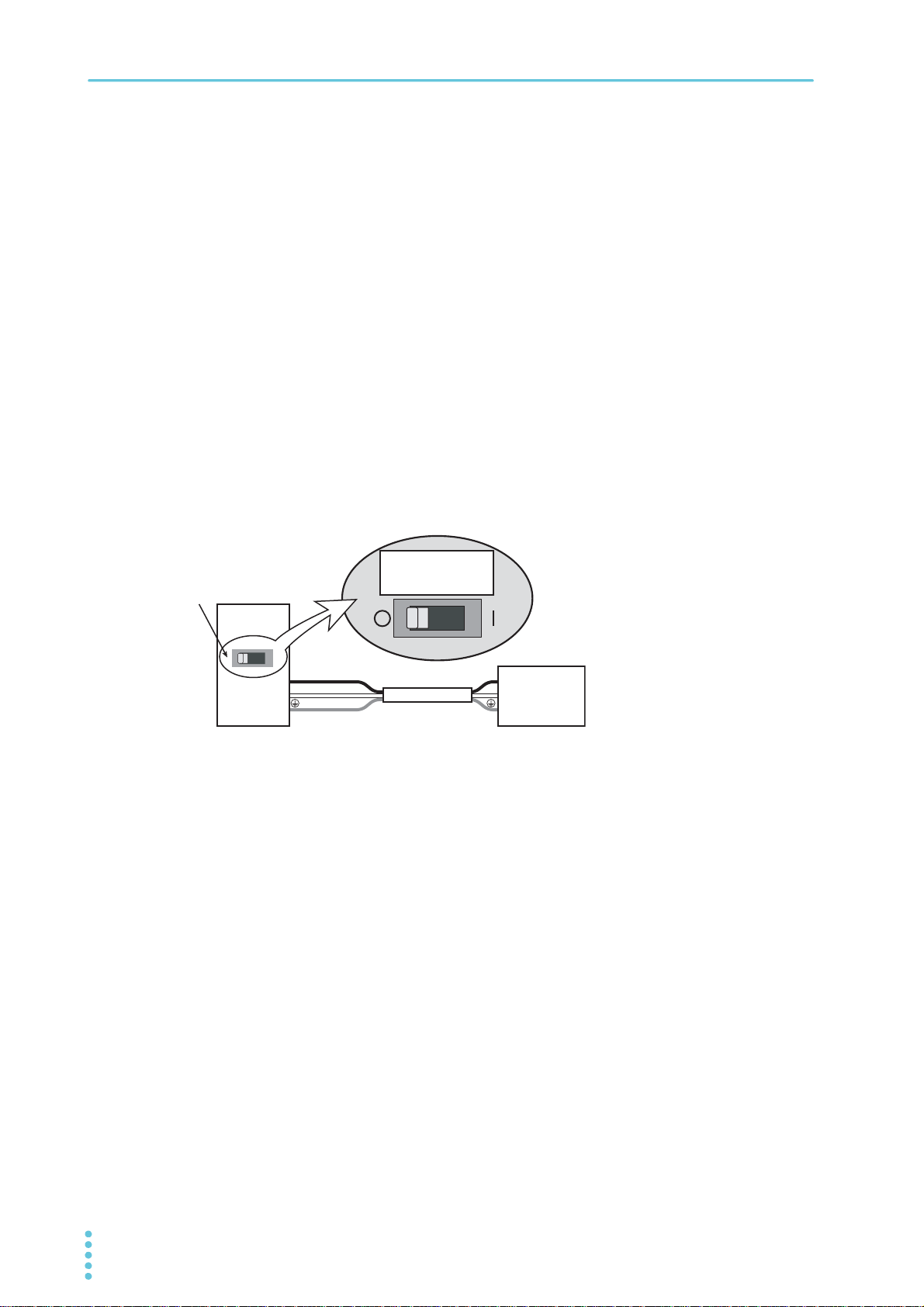
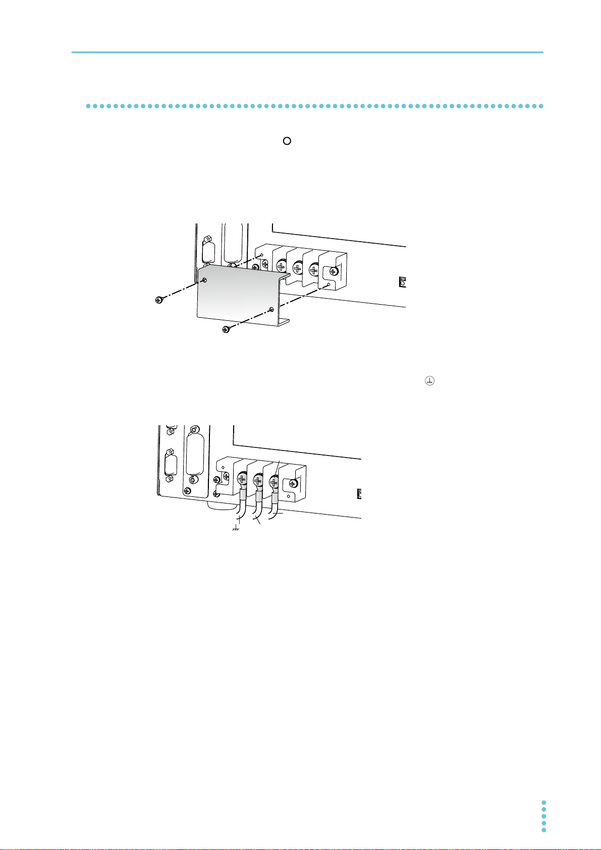
Unfasten the three M4 screws from the terminal block cover, and remove the cover.
3
Connect the power cord according to the indications on the AC INPUT terminal
4
block.
20 User’s Manual PCR-WE/PCR-WE2
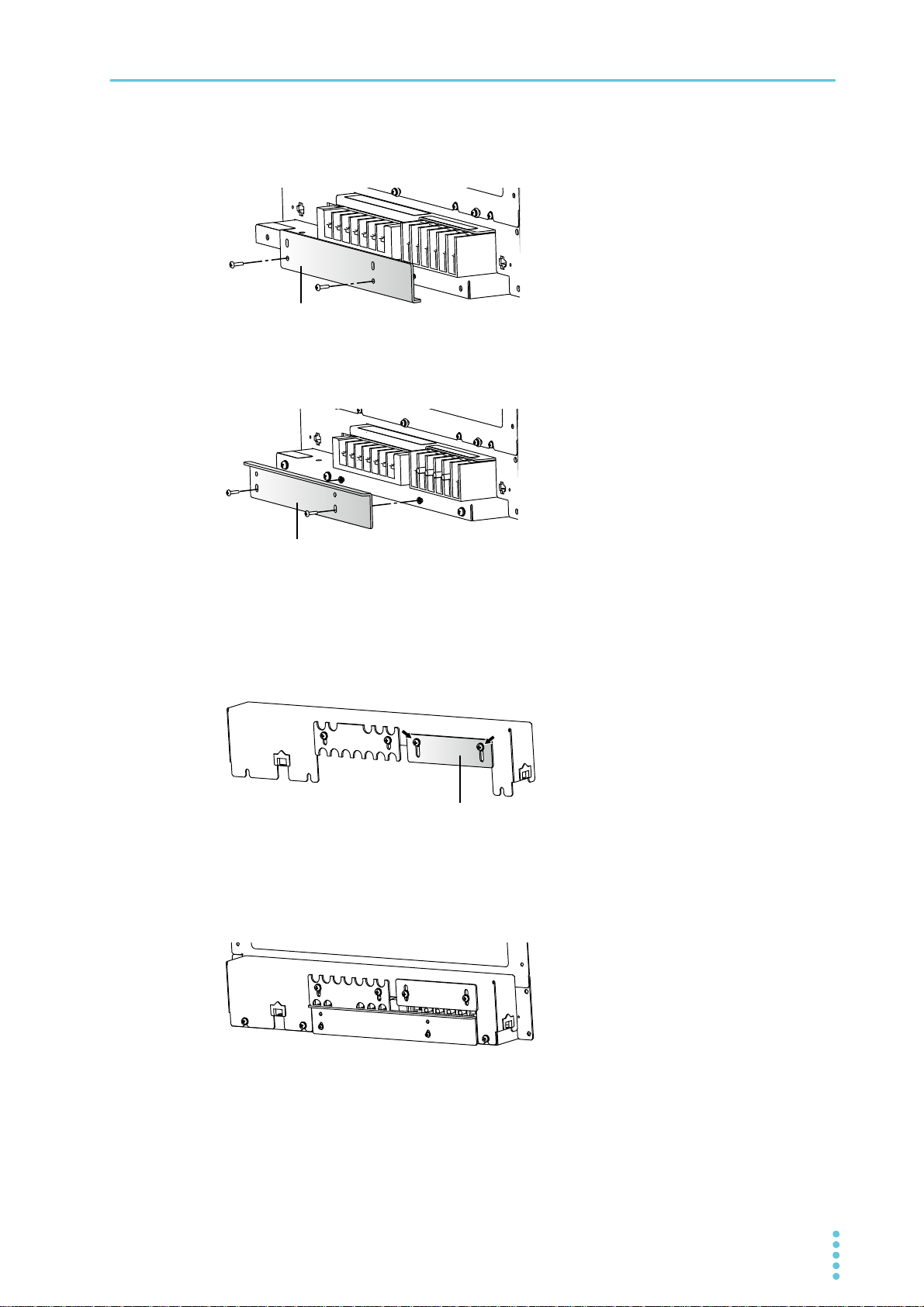
Installation | Connecting the Power Cord
Bottom terminal block cover
Input terminal cover
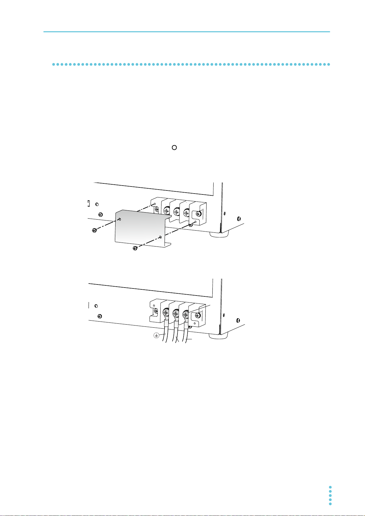
Unfasten the two M4 screws from the bottom terminal block cover, and remove the
5
cover.
Change the direction of the bottom terminal block cover, and attach it.
6
This will keep the crimping terminals from being exposed.
Bottom terminal block cover
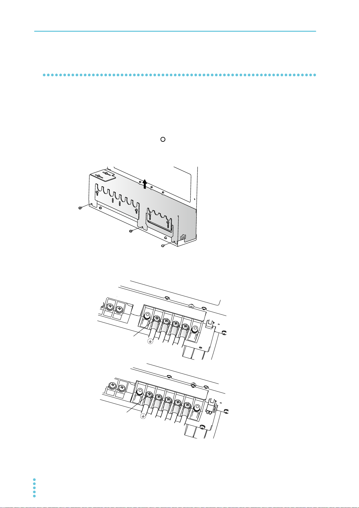
Turn off the switchboard’s circuit breaker.
7
Connect the power cord according to the indication on the switchboard.
8
Loosen the two screws until the INPUT terminal cover can move.
9
Fasten the terminal cover you removed in step 3 with the three screws.
10
Slide the INPUT terminal cover until it touches the wires, and then fasten the
11
screws.
PCR-WE/PCR-WE2 User’s Manual 21
Turn on the switchboard's breaker.
12
This completes the connections.
Installation | Connecting the Power Cord
Example of three-phase 200 V input
N
T
S
R
M5
M8
T
S
R
Three-phase 200 V input
Three-phase 400 V input
Connecting the PCR18000WE2/PCR24000WE2/ PCR30000WE2/PCR36000WE2
Check that the AC power line meets the nominal input rating of the product.
1
Acceptable input voltage (any nominal supply voltage in the following ranges):
Three-phase 200 V input: 200 Vac to 240 Vac (line voltage)
Three-phase 400 V input: 380 Vac to 480 Vac (phase voltage)
Frequency: 50 Hz or 60 Hz
Turn the POWER switch off ( ).
2
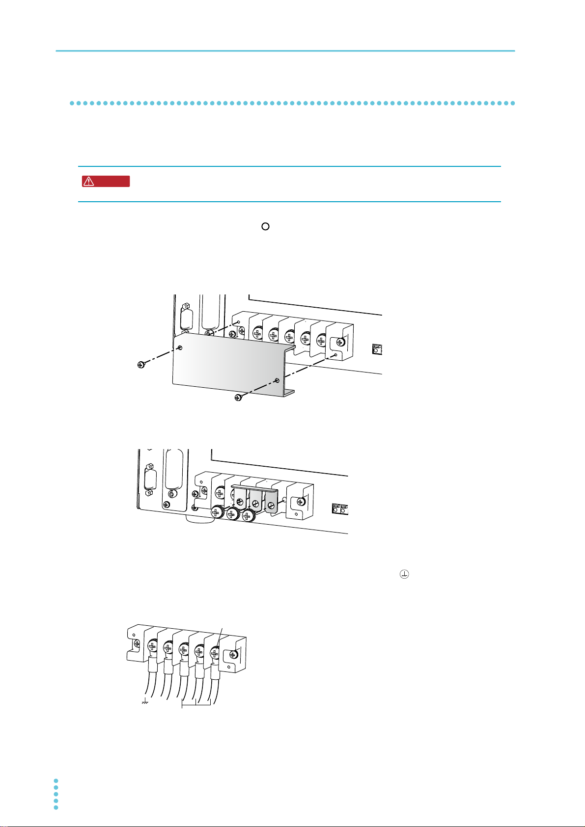
Unfasten the three M4 screws from the terminal block cover, and remove the cover.
3
Connect the power cord according to the indications on the AC INPUT terminal
4
block.
Turn off the switchboard’s circuit breaker.
5
22 User’s Manual PCR-WE/PCR-WE2
Installation | Connecting the Power Cord
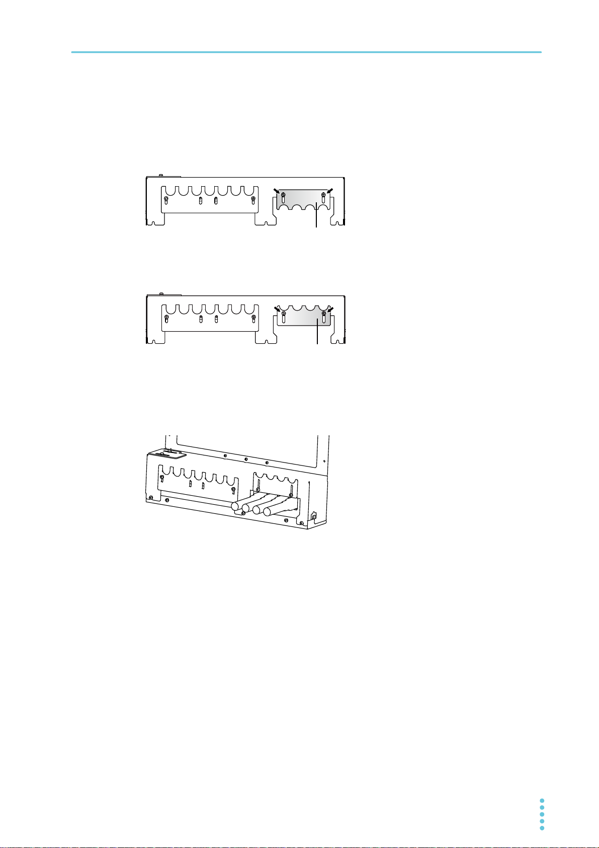
INPUT terminal cover
Example of PCR36000WE2 (three-phase
200 V input)
Connect the power cord according to the indication on the switchboard.
6
For the three-phase 200 V input model (excluding the PCR36000WE2), remove the
7
two M3 screws, change the orientation of the INPUT terminal cover, and fasten with
the screws you just removed.
Tighten the screws loosely so that the INPUT terminal cover can still be moved.
For three-phase 400 V input model or PCR36000WE2 (three-phase 200 V input),
loosen the two M3 screws until the INPUT terminal cover can move.
INPUT terminal cover
Fasten the terminal cover you removed in step 3 with the three screws.
8
Slide the INPUT terminal cover until it touches the wires, and then fasten the
9
screws.
Turn on the switchboard's breaker.
10
This completes the connections.
PCR-WE/PCR-WE2 User’s Manual 23
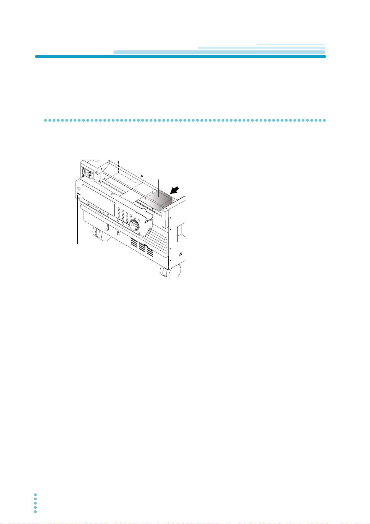
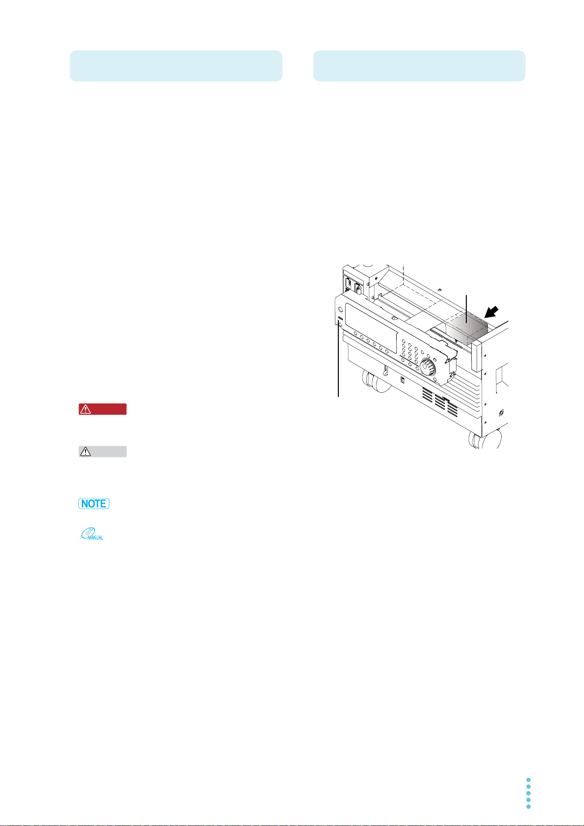
Installation
When shipped from the factory, the PCR6000WE2,
PCR12000WE2, PCR18000WE2, PCR24000WE2,
PCR30000WE2, and PCR36000WE2 have connectors
stored on the back of the control panel.
Control panel.
External control
(DIGITAL I/O)
connector
Turning the Power On
When you turn on the POWER switch for the first time after purchase, do it without any load connected in
order to check the status of the product.
Preventing the shutdown function from activating
Connect the included external control (DIGITAL I/O) connector to the DIGITAL I/O connector to release the
shutdown function (p.165 , p.169 ).
If you turn on the POWER switch without connecting the connector, you will not be able to turn the output
on because the shutdown function will be activated.
24 User’s Manual PCR-WE/PCR-WE2
Turning the POWER switch on
Check that nothing is connected to the OUTPUT terminal block on the rear panel.
1
Check that the power cord is connected correctly.
2
Check whether the supplied external control connector is connected to the
3
DIGITAL I/O connector on the rear panel.
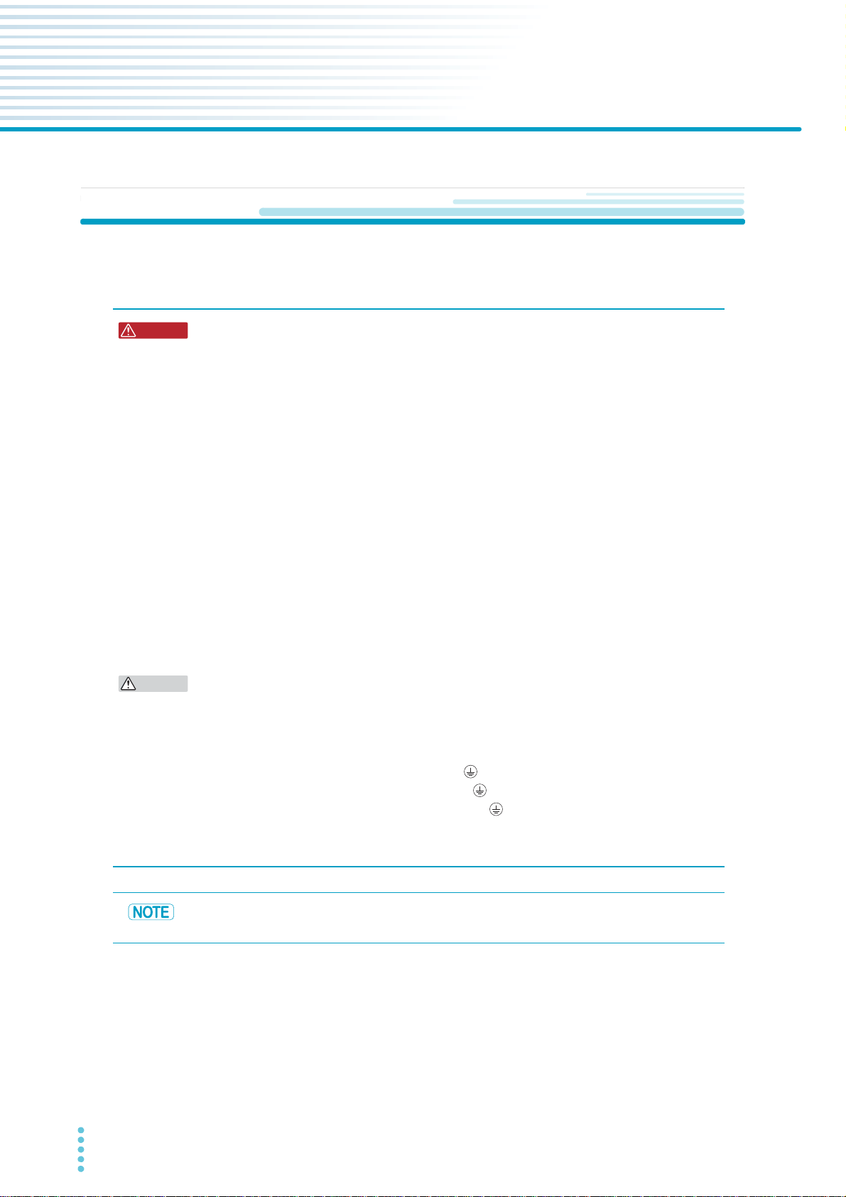
Check that the POWER SELECTOR switch is set to "MASTER."
4
Flip the POWER switch to the ( ) side to turn the PCR-WE on.
5
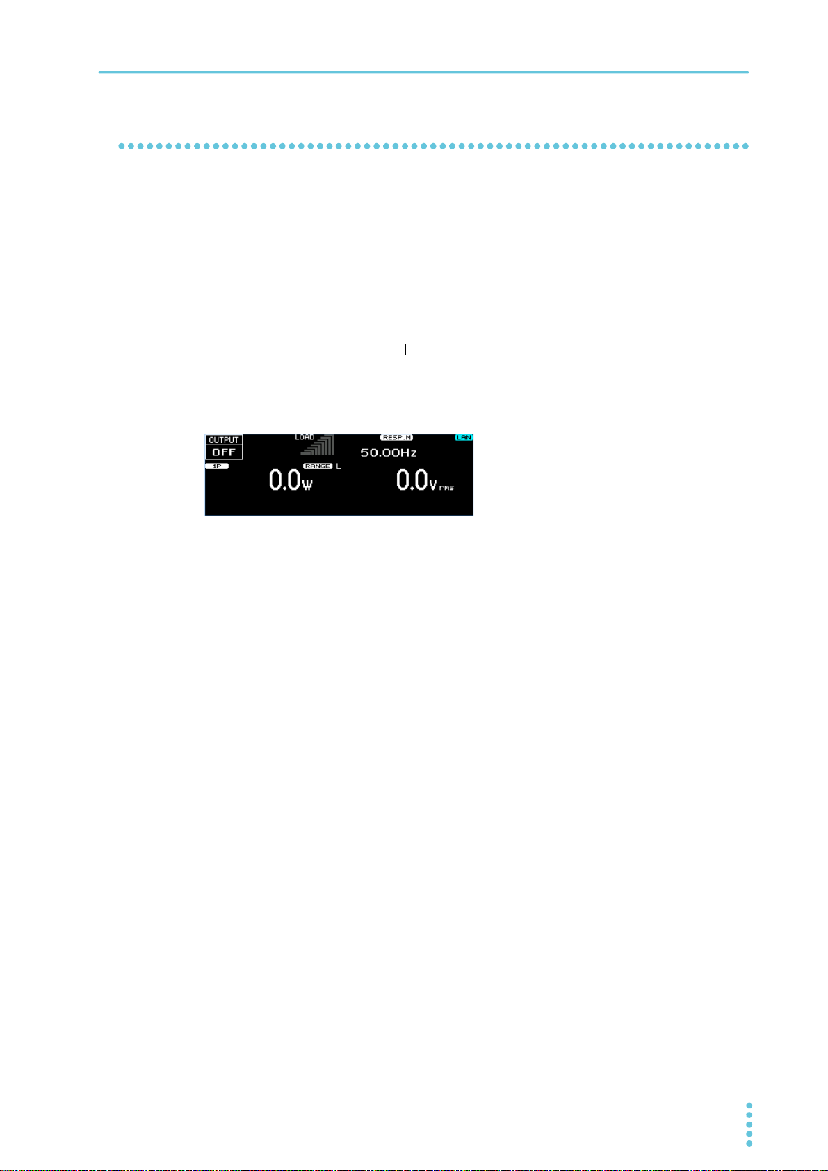
The firmware version is displayed for a few seconds. If no errors are detected, the home position
(basic screen) appears.
This completes the power-on procedure.
Installation | Turning the Power On
If the POWER switch is turned on for the first time after purchase, the product starts in the factory
default condition. When the power is turned on the next time, the product starts with the settings
that were in use the last time that the POWER switch was turned off. You can set the condition that
the product will be in when the power is turned on.
If an alarm number or trouble number is displayed, see “Alarms and Trouble” (p.237).
PCR-WE/PCR-WE2 User’s Manual 25

Installation | Turning the Power On
CAUTION
Setting the condition that the product will be in when the POWER switch is turned on
In the factory default condition, when you turn the POWER switch on, the product starts in the same state
as it was in the last time it was turned off (the output set to off). You can set the condition that the product
will be in when the POWER switch is turned on.
Press CONFIG (SHIFT+OPR MODE) > PON STAT (F3) to set the condition that the panel settings will be
in when the POWER switch is turned on.
Parameter Title Description
RST (F1) PowerOn State Starts by resetting the product and with the
output set to off.
RCL(F2) Starts according to the settings egistered in
setup memory 0.
AUTO(F3) Starts in the same state as the product was in
the last time it was turned off.
The output condition is according to PowerOn
Output State.
You can set the output condition for when the power is turned on. This is invalid when the power-on state
is set to RST or RCL.
Press OTHERS (SHIFT+MEMORY) > 1/2(F6) > PON OUTP (F4) to set the output condition for when the
POWER switch is turned on.
Parameter Title Description
SAFE(F2) PowerOn Output State Starts with the output turned off.
FORCE(F3) Starts with the output turned on.
Turning the POWER switch off
Flip the POWER switch to the ○ side to turn the product off.
In the factory default condition, when the POWER switch is turned on, all settings except for the output
condition (OUTPUT on/off) take on the values that were in use the last time that the POWER switch was
turned off.
If the POWER switch is turned off immediately after the settings have been changed, the last settings may
not be stored.
Risk of malfunction. After turning the POWER switch off, wait at least 5 seconds before
turning it back on.
Turning off the POWER switch in an emergency
In an emergency, turn off the switchboard breaker to separate the product from the AC power line.
Provide adequate space around the circuit breaker so that the POWER switch can be turned off at any
time.
26 User’s Manual PCR-WE/PCR-WE2
Connecting the Load
WARNING
CAUTION
The maximum current that this product can generate varies depending on the model. It also varies
depending on the output voltage and frequency. Ensure that the output power capacity is sufficient for the
load capacity. The maximum output currents (for rms output voltage of 1 V to 100 V or 2 V to 200 V and
frequency greater than 40 Hz or DC) for the different models are shown in the following table.
Model Maximum output current
1P output 1P3W output, 3P output
L range H range L range H range
PCR1000WE 10 A 5 A — —
PCR2000WE 20 A 10 A — —
PCR3000WE2 30 A 15 A 10 A 5 A
PCR6000WE2 60 A 30 A 20 A 10 A
PCR12000WE2 120 A 60 A 40 A 20 A
PCR18000WE2 180 A 90 A 60 A 30 A
PCR24000WE2 240 A 120 A 80 A 40 A
PCR30000WE2 300 A 150 A 100 A 50 A
PCR36000WE2 360 A 180 A 120 A 60 A
Installation
Risk of electric shock
• Do not use the terminal block with the terminal cover removed.
• Use load cables with a voltage rating that meets or exceeds the product’s isolation
voltage (±438 V).
• Risk of electric shock. Before you connect cables to the OUTPUT terminal block, be
sure to turn the POWER switch off, and then turn off the switchboard.
Risk of fire
• Use load cables whose capacity is adequate for the maximum output current and
with sturdy, flame-resistant insulation.
• A sudden load variation exceeding the rating may cause a large overshoot.
• Risk of heat buildup or spark emission. Fasten the wires securely at the recommended
torque.
The L and N terminals of the OUTPUT terminal block are isolated from the input power
supply. The polarity does not constitute a problem in terms of safety. The polarity matters in
synchro mode (in which the product is synchronized with the input power supply) and DC
mode, so check the polarity of the load before you connect it to the product. You can use
either L or N to ground the product.
Tightening torque of input terminal connecting screws
The recommended and upper limit values are for when attaching the cable and short bar. Use within the
upper limit.
Recommended [N•m] Upper limit [N•m]
M5 2.0 2.4
M6 2.5 3.0
M8 5.5 6.6
PCR-WE/PCR-WE2 User’s Manual 27

Installation | Connecting the Load
Connecting to the OUTPUT terminal block
We recommend that you run the load wires alongside each other and tie them together at several points
with cable ties. Connect between the output terminal and load with the shortest wires possible.
Preparing wires
Use noncombustible wires that have diameters that correspond to the output current to connect to the
load.
Requirements of single-core wires that are used to connect to the load
A cable’s temperature is determined by the resistive loss based on the current, the ambient temperature,
and the cable’s external thermal resistance. The following table shows the current capacity of heatresistant vinyl cables that have a maximum allowable temperature of 60 °C when one of the cables is
separated and stretched out horizontally in air in an ambient temperature of 30 °C. The current must be
reduced under certain conditions, such as when vinyl cables that have a low heat resistance are used,
when the ambient temperature is 30 °C or greater, or when cables are bundled together and little heat is
radiated.
Nominal crosssectional area [mm
0.9 18 (0.82) 17
1.25 16 (1.31) 19
2 14 (2.08) 27
3.5 12 (3.31) 37
5.5 10 (5.26) 49
8 8 (8.37) 61
14 6 (13.3) 88
22 4 (21.15) 115
30 2 (33.62) 139
38 1 (42.41) 162
50 1/0 (53.49) 190
60 2/0 (67.42) 217
80 3/0 (85.03) 257
100 4/0 (107.2) 298
*1. * Excerpt from Japanese laws related to electrical equipment.
AWG (reference cross-sectional
2
area) [mm
]
2
]
Allowable current*1 [A]
(at Ta = 30 °C / 86 °F)
For cables other than those specified in this table, consult with a qualified engineer.
28 User’s Manual PCR-WE/PCR-WE2
Installation | Connecting the Load
L
M6
Connecting the PCR1000WE/PCR2000WE
Turn the POWER switch off ( ).
1
Turn off the switchboard’s circuit breaker.
2
Unfasten the two M3 screws from the OUTPUT terminal cover, and remove the
3
cover.
Securely connect the load cables to the OUTPUT terminal block.
4
If the load has a ground (GND) terminal, be sure to connect it to the (ground) terminal of the
product’s OUTPUT terminal block. Be sure to use a wire whose diameter is greater than or equal to
the diameter of the wires used to connect the load.
N
Fasten the cover that you removed in step 3 with the two screws.
5
This completes the connections.
PCR-WE/PCR-WE2 User’s Manual 29
Installation | Connecting the Load
WARNING
L
N
M6
Connect three cables
and bundle them together.
Connecting the PCR3000WE2
For single-phase output
Risk of electric shock. Be sure to connect the three N cables. There is a risk of
touching the unused terminals through the gap of the OUTPUT terminal cover.
Turn the POWER switch off ( ).
1
Turn off the switchboard’s circuit breaker.
2
Unfasten the two M3 screws from the OUTPUT terminal cover, and remove the cover.
3
Attach the short bar.
4
Securely connect the load cables to the OUTPUT terminal block.
5
If the load has a ground (GND) terminal, be sure to connect it to the (ground) terminal of the
product’s OUTPUT terminal block. Be sure to use a wire whose diameter is greater than or equal to
the diameter of the wires used to connect the load.
30 User’s Manual PCR-WE/PCR-WE2
Fasten the cover that you removed in step 3 with the two screws.
6
This completes the connections.
 Loading...