

Kikusui PBZ20-20, PBZ40-10, PBZ60-6.7, PBZ80-5 User Manual

PART NO. IB027582
Mar. 2015
Communication
Interface Manual
BIPOLAR POWER SUPPLY PBZ Series
PBZ20-20
PBZ40-10
PBZ60-6.7
PBZ80-5
About the Operation Manuals 2
Notations Used in This Manual 2
Remote Control Overview 3
VISA Library 4
Interface Setup 5
Using the RS232C Interface 5
Using the GPIB Interface 7
Using the USB Interface 8
Using the LAN Interface (Option) 9
Accessing and Operating the PBZ from a Web
Browser (LAN interface) 11
Message Overview 14
SCPI Command Syntax 14
Parameters 17
Command Description in This Manual 19
IEEE 488.2 Common Commands 20
Output Setting Commands 24
CV/CC Mode and Bipolar/Unipolar Mode 24
Selecting the Signal Source (Internal or
External) and Setting the External Signal Source
24
DC Signal Setting 26
Output, Trigger Signals, and Screen Contrast 36
Protection Features Commands 40
Mode 40
Activation points (OCP/OVP) 40
Activation points (I.LIM/ V.LIM) 42
Mode and activation points (legacy command)
43
Clearing Alarms 44
Measurement Function Commands 45
Trigger Function 46
Memory Function Commands 54
Preset Memory 54
Setup Memory 54
Sequence Function Commands 56
Editing Programs and Steps 56
Executing Programs 64
Editing Scripts 65
System Settings Commands 66
CONFIG Settings 66
Basic System Settings 70
IEEE 488.2 Register Model 74
SCPI Register Model 76
Default State 81
Processing time of Commands 86
List of Messages 87
List of Errors 96
Tutorial (Visual Basic 2008) 99
INDEX103
About the Operation Manuals
There are five PBZ Series Manuals listed as follows.
• Setup Guide
This manual is intended for first-time users of this product. It
provides an overview of the product and notes on usage. It also
explains how to set up the product for testing the DUT. Always
read this manual before using the product.
• User’s Manual
This manual is intended for first-time users of this product. It
provides an overview of the product and notes on usage. It also
explains how to configure the product, operate the product,
perform maintenance on the product, and so on.
Paper
Paper
PDF
PDF
Trademarks
Company names and product names used in this manual are
trademarks or registered trademarks of their respective
companies.
Copyrights
The contents of this manual may not be reproduced, in whole or in
part, without the prior consent of the copyright holder.
The specifications of this product and the contents of this manual
are subject to change without prior notice.
© 2013 Kikusui Electronics Corporation
Notations Used in This Manual
• Communication Interface Manual (this manual)
This manual contains details about remotely controlling the
tester using SCPI commands.
The interface manual is written for readers with sufficient basic
knowledge of how to control measuring instruments using a
PC.
• Quick Reference
This manual explains Panel description and operation briefly.
• Safety Information
This document contains general safety precautions for this
product. Keep them in mind and make sure to observe them.
PBZ series manuals is intended for users of the product or persons
teaching other users on how to operate the bipolar power supply.
PBZ series manuals assumes that the reader has electrical
knowledge.
PDF is provided on the included CD-ROM.
Adobe Reader 6.0 or later is required to view the PDF file.
If you find any misplaced or missing pages in this manual, it will be
replaced. If the manual gets lost or soiled, a new copy can be
provided for a fee. In either case, please contact your Kikusui agent
or distributor, and provide the “Kikusui Part No.” given on the
cover.
Every effort has been made to ensure the accuracy of this manual.
However, if you have any questions, or find any errors or
omissions, please contact your Kikusui agent or distributor.
After you have finished reading this manual, store it so that you
can use it for reference at any time.
Paper
Paper
Paper
Paper
PDF
PDF
PDF
• The bipolar power supplies PBZ20-20 and PBZ40-10 are also
referred to as the PBZ20-20 and PBZ40-10 respectively.
• The word “PC” used in this manual is a generic term for personal
computers and workstations.
• The following markings are used in this manual.
WARNING
Indicates a potentially hazardous situation which, if
ignored, could result in death or serious injury.
CAUTION
Indicates a potentially hazardous situation which, if
ignored, may result in damage to the product or other
property.
Indicates information that you should know.
DESCRIPTION
Explanation of terminology or operation principle.
See
Indicates reference to detailed information.
Product firmware versions
This manual applies to products with firmware versions 2.2X.
When contacting us about the product, please provide us with:
The model (marked in the top section of the front panel)
The firmware version (see the user’s manual)
The serial number (marked in the bottom section of the rear
panel)
Before reading this manual
First read the User’s Manual, which includes information on the
product’s hardware, to avoid connecting or operating the product
incorrectly.
2 PBZ_INTERFACE

1
Remote Control Overview
This chapter provides a general explanation of the remote control function.
In addition to controlling the PBZ from the front panel, you can control it remotely through the
following standard-equipped interfaces.
• RS232C interface
• GPIB interface
• USB interface
• LAN interface (factory option)
If the factory option interface board is installed, you can use LAN.
You cannot control the PBZ through RS232C, GPIB, USB, and LAN at the same time.
The remote interfaces comply with IEEE Std 488.2-1992 and SCPI Specification 1999.0.
See
p. 14
Familiarize yourself with the syntax of the SCPI commands that are used with the PBZ before you
use them to control the product.
The RMT icon is displayed in the screen’s status display area when the PBZ is in remote mode. To use
the front panel to switch the PBZ back to local mode, press the LOCAL key.
Measurement instrument interface standards
The PBZ complies with the following standards.
• IEEE Std 488.2-1992 IEEE Standard Codes, Formats, Protocols, and Common Commands For
Use With IEEE Std 488.1-1987
• IEEE Std 488.1-1987 IEEE Standard Digital Interface for Programmable Instrumentation
• Standard Commands for Programmable Instruments (SCPI) version 1999.0
• Universal Serial Bus Specification Rev 2.0
• Universal Serial Bus Test and Measurement Class Specification (USBTMC) Rev 1.0
• Universal Serial Bus Test and Measurement Class, Subclass USB488 Specification (USBTMC-
USB488) Rev 1.0
• TCP/IP Instrument Protcol Specification VXI-11
• LXI 1.4 Core Device Specification 2011
PBZ_INTERFACE 3

Remote Control Overview
VISA Library
To use the VISA library (VISA COM) with the I/O library, the VISA library must be installed on the
controller (the host PC).
To use the USB interface to control the PBZ, a driver that supports the USB Test & Measurement
Class (USBTMC) must be installed on the controller. The USBTMC driver is installed automatically by
the VISA library.
When the product is controlled by the LAN interface, middleware which applies to the VXI-11
protocol is required. Middleware is automatically installed by VISA library.
VISA (Virtual Instrument Software Architecture) was developed by the VXIplug&play Systems
Alliance. It is the standard specification for measurement instrument connection software.
You have to install one of the following VISA libraries (driver software that is implemented
according to the VISA specifications).
Do not install multiple VISA libraries on the same PC. Doing so may cause errors.
VISA libraries that are older than the versions listed here do not support USB. Windows 95 and
Windows NT 3.5x and 4.0 do not support USB.
• NI-VISA by National Instruments Corporation (version 5.1.1 or later)
• Keysight VISA by Keysight Technologies (formerly Agilent Technologies), Inc. (Keysight IO
Librarys Suite 16.0 or later)
• KI-VISA version 5.0..4 or later
KI-VISA is an original VISA library developed by Kikusui Electronics Corporation that supports the
VXIplug&play VISA specifications. You can download the most recent version of this library from the
Kikusui Electronics Corporation website (http://www.kikusui.co.jp/download/). If NI-VISA or
Keysight VISA is already installed on your PC, you do not need to install KI-VISA.
You can download the “KI-VISA Library Programming Guide” from the Kikusui Electronics
Corporation website.
4 PBZ_INTERFACE
2
Interface Setup
Using the RS232C Interface
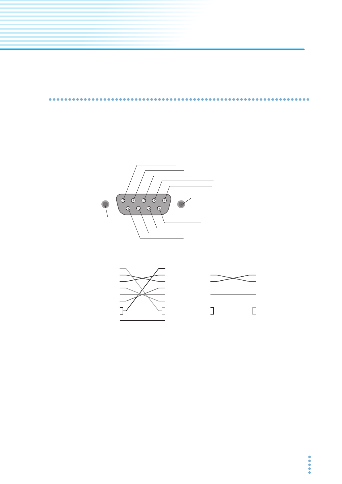
The PBZ RS232C interface is a standard D-sub, 9-pin male connector.
Check that the PBZ and your PC are off, and connect them with a standard cross cable (null-modem
cable).
Use a D-sub, 9-pin, female-to-female AT cross cable. The figure below shows the port pinout.
The PBZ does not use hardware handshaking (cross cable example 2).
1: CD (carrier detect)
2: RXD (receive data)
3: TXD (transmit data)
4: DTR (data terminal ready)
5: GND (signal ground)
#4-40UNC
inch screw
#4-40UNC
inch screw
Facing the PBZ rear panel
1
2
3
4
5
6
7
8
9
D-sub 9-pin
female
Cross cable example 1
9: RI (ring indicator)
8: CTS (clear to send)
7: RTS (request to send)
6: DSR (data set ready)
1
2
3
4
5
6
7
8
9
D-sub 9-pin
female
1
2
3
4
5
6
7
8
9
D-sub 9-pin
female
Cross cable example 2
1
2
3
4
5
6
7
8
9
D-sub 9-pin
female
PBZ_INTERFACE 5

Interface Setup
RS232C Settings
Press Config key to set the interface type and communication parameters using CONFIG[6].
Protocol
The RS232C protocol. In the following table, the underlined values are the factory default settings.
Item Setting
Connector Rear panel, D-sub, 9-pin connector
Baud rate 1 200, 2 400, 4 800, 9 600, 19 200, or 38 400 bps
Data length 7 or 8
Stop bits 1 or 2
Parity None (fixed)
Flow control ON or OFF
Flow control
Use flow control for RS232C transmission and reception. Device Control (DC) codes are used for this
purpose.
Data may not be received properly if flow control is not used.
Code Function ASCII code
DC1 (Xon) Request to send 11H
DC3 (Xoff) Transmission stop request 13H
PBZ
TXD
RXD
DC3
After receiving DC3, the RS232C terminal must
pause transmission within 10 characters.
Within 10
characters
Pause
DC1
Resume transmission
Break signal
The break signal is used as a substitute for the IEEE488.1 dcl/sdc (Device Clear, Selected Device
Clear) message.
6 PBZ_INTERFACE

Using the GPIB Interface
Setting the GPIB address
The factory default GPIB address is “1.” You can set the address to a number from 1 to 30.
Press Config key to set the interface type and GPIB address using CONFIG[6].
GPIB feature
Function Subset Description
Source handshaking SH1 Full capability
Acceptor handshaking AH1 Full capability
Talker T6 Function available
Listener L4 Function available
Service request SR1 Full capability
Remote local RL1 Full capability
Parallel polling PP0 No capability
Device clear DC1 Full capability
Device trigger DT1 Full capability
Controller C0 No capability
Electrical interface E1 Open-collector driver
Interface Setup
Service request
The PBZ is equipped with service request and serial polling functions.
PBZ_INTERFACE 7

Interface Setup
Using the USB Interface
To use the USB interface to control the PBZ, a driver that supports the USB Test & Measurement
class (USBTMC) must be installed on the controller. The USBTMC driver is installed automatically by
the VISA library.
USB settings
Press Config key to set the interface type using CONFIG[6].
USB feature
• Complies with USB specification 2.0
• Complies with USBTMC specification 1.0 and USBTMC-USB488 specification 1.0
• Baud rate: 12 Mbps maximum (full speed)
• VID (vendor ID): 0x0B3E
• PID (product ID): 0x1012
Service request
The PBZ is equipped with service request and serial polling functions.
8 PBZ_INTERFACE

Using the LAN Interface (Option)
The LAN interface is a factory option.
To use the LAN interface to control the PBZ, middleware that supports the VXI-11 protocol must be
installed on the controller. The middleware is installed automatically by the VISA library.
There is a Web browser interface to the PBZ embedded in the LAN interface board. You can
configure the LAN interface settings from your PC’s Web browser.
For information on topics such as connecting to your corporate LAN, your IP address, your host
name, and security, contact your network administrator.
LAN connections
Use a standard LAN cable (category 5 and straight) to connect the PBZ to a network hub or router.
Use a crossover cable when making a direct connection.
LAN settings
Usually, LAN settings are configured using a DHCP server. If you want to use a fixed IP address, you
cannot set it from the panel. Set it from a Web browser.
Interface Setup
See
p. 11
CONFIG settings
Press Config key to set the interface type and communication parameters using CONFIG[6].
Normally, you should set DHCP and AUTO IP to ON to set the IP address automatically.
For direct connections, set DHCP to OFF and AUTO IP to ON and set the IP address automatically.
You cannot set the IP address from the panel. To set a fixed IP address, first set the IP address
automatically, and then set a fixed address by accessing the PBZ through a Web browser.
When you are going to use a fixed IP address over a long period of time or at intervals, we
recommend that you specify a host name. To set a host name, access the PBZ through a Web
browser.
Service request
The PBZ is equipped with service request and serial polling functions.
LAN feature
Depending on the operation that you perform through your Web browser, the PBZ may need to
connect to the Internet.
Complies with the LXI 1.4 Core 2011
Complies with the VXI-11/ SCPI-RAW protocol
Baud rate: 100 Mbps maximum (auto negotiation)
DHCP client feature
AUTO IP feature
From your Web browser, you can (Internet Explorer version 8.0 or later; Mozilla Firefox version 3.6 or
later; Safari version 5.1 or later; Google Chrome version 5.0 or later):
Change LAN and security settings.
Use simple control applications.
Update the LAN board
PBZ_INTERFACE 9
Interface Setup
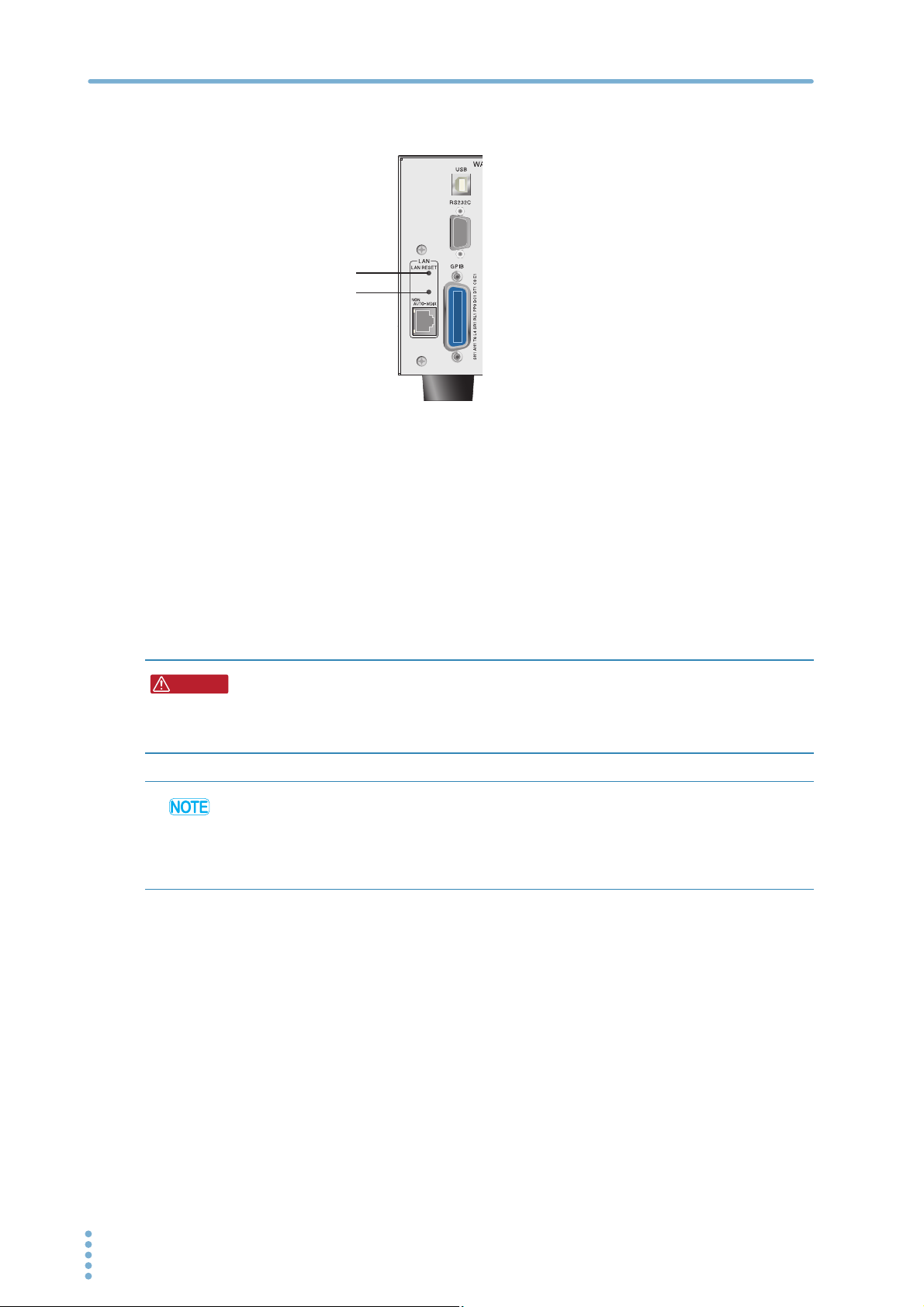
LAN RESET switch and DEFAULT switch
WARNING
LAN RESET switch
DEFAULT switch
* Use a thin-tipped tool to
press the switches.
DEFAULT
■ LAN RESET switch
Holding down this switch for 3 seconds resets the LAN interface settings, except for Hostname and
Hostname Description, to their factory default values. You can use this switch if you forget the
security password.
■ DEFAULT switch
Hold down this switch for 3 seconds or more to reset the LAN interface settings to the factory
default values. You can use this switch if you forget the security password or IP address.
Neither of these switches affects the PBZ’s panel settings. If the PBZ is in remote mode, pressing one
of these switches will change the PBZ back into local mode (panel operation).
• The LAN interface can be accessed from anywhere on the network that the PBZ is
connected to. Change the security settings if necessary.
Refer to " Accessing and Operating the PBZ from a Web Browser (LAN interface)" on p. 11
for setting procedure.
• Do not use the DEFAULT and LAN RESET switches carelessly. This may cause the LAN interface to
malfunction.
• The LAN interface is different from the other remote interfaces in that you have to use the
“SYSTem:REMote” command to switch the PBZ to remote mode. When you are carrying out
remote programming, send this command at the beginning of the program.
10 PBZ_INTERFACE
Interface Setup
Accessing and Operating the PBZ from a Web Browser (LAN interface)
For LAN interface, the detailed setting can be operated from the browser on the PC.
The URL of Web site is defined as adding "http://" in front of the IP address.
The URL can be entered directly on the address bar of the browser by confirming the IP address of
the config setting (CONFIG[6] > LAN > IP ADDRESS).
(Example) When the IP address is 169.254.7.8
http://169.254.7.8
When VISA library is used, there is the function to retrieve the VXI-11 measuring instrument by the
application program provided by VISA vendors (National Instruments NI-MAX, Agilent Connection
Expert, and Kikusui KI-VISA Instrument Explorer, etc.). You can access the PBZ by clicking on the
Web link from the retrieval results.
The following browsers are applied.
• Internet Explorer 8.0 or later
• Mozilla Firefox 3.6 or later
• Google Chrome 5.0 or later
• Safari 5.1 or later
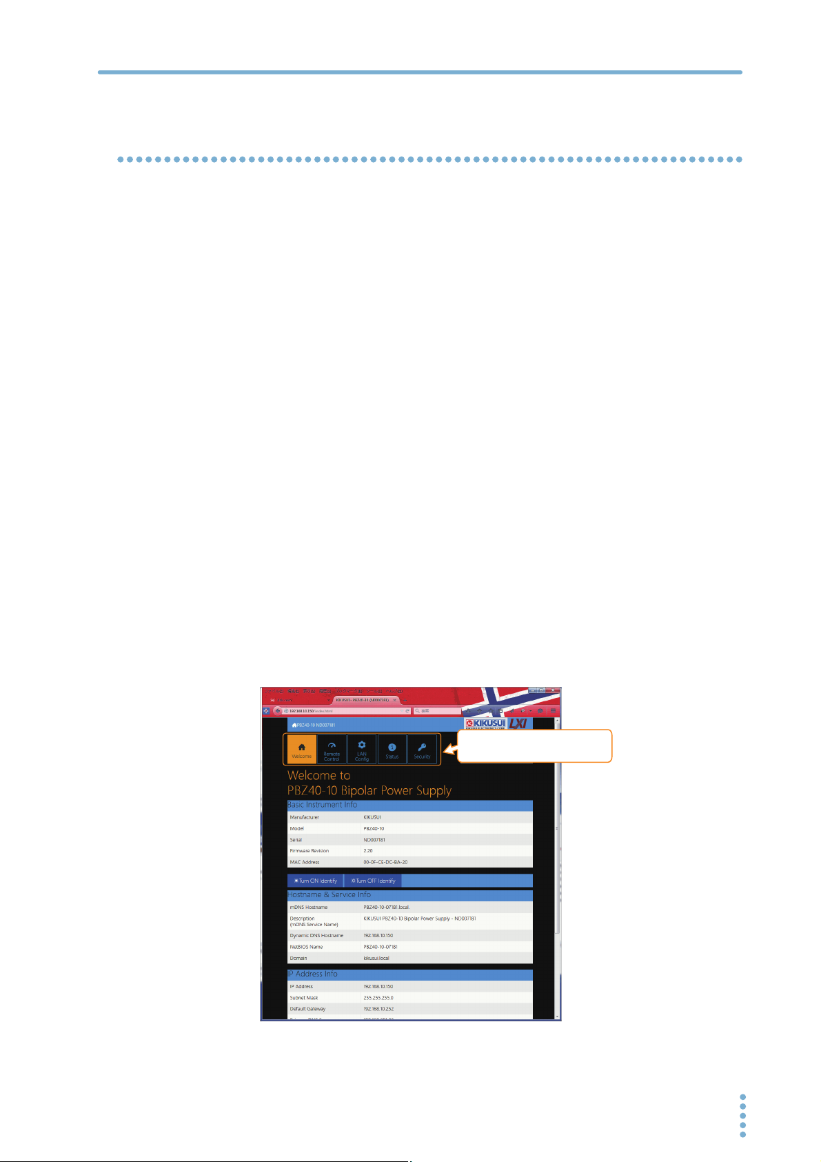
WELCOME page
When you access the PBZ from a Web browser, the WELCOME page is displayed first.
The instrument information, network information, and VISA resource (I/O resource) information
appear on the display.
Clicking Turn ON Identify displays “Device Identify” on the PBZ series front panel display. This
enables you to check which PBZ series is being controlled through the LAN interface.
Click the navigation menu to move to the other page.
Navigation menu
Move to the page which clicked.
PBZ_INTERFACE 11
Interface Setup
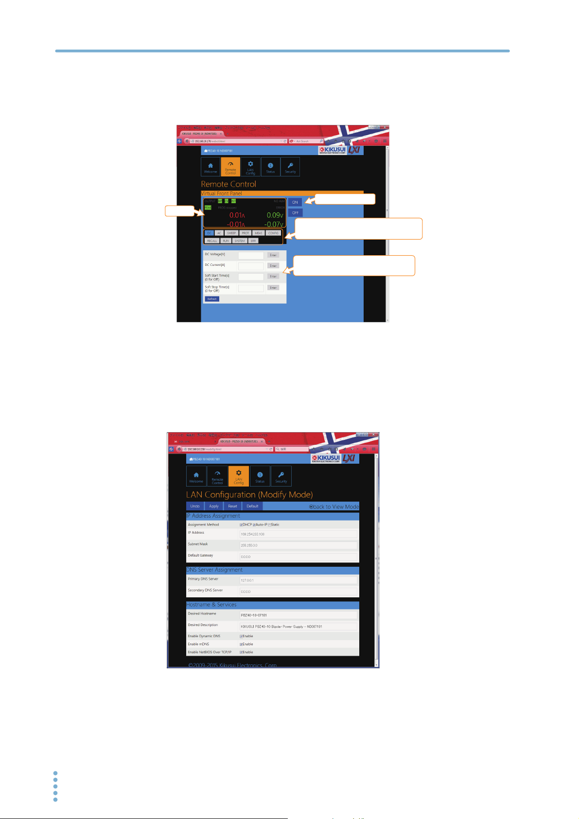
Remote Control page
You can set and control voltage, current, and output settings; view measured values; configure the
protection feature.
Output: on/off
Monitor
The input form for the item
you click appears in the lower area.
Enter the settings and click
Enter
to change the PBZ settings.
LAN config page
Config page for the network settings.
Click Modify Now to assign the IP address, set the host name, and so on.
If you set the host name, you can use it in place of the IP address to access the LAN interface.
After you enter the settings, click Apply to apply the settings.
12 PBZ_INTERFACE

STATUS page
This page shows the LAN board revision and OSS license information.
Interface Setup
SECURITY page
This page is for the security setting.
This page can allow you to set the change of the password protection.
The password protection is an effective security features to the Web site. It prevents from being
changed inadvertently. The password can be used for any alphanumeric characters, the hyphen,
and the underscore.
PBZ_INTERFACE 13

3
Message Overview
The information that is transferred between the controller (the host PC) and the PBZ is referred to as
“messages.”
The PBZ uses the SCPI language for these messages.
The messages that the PC sends to the PBZ are commands. The messages that the PBZ sends to the
PC are responses.
Commands are used to execute functions or change settings on the PBZ or to query the PBZ’s
settings or status. Responses are used to return the PBZ’s settings or status.
SCPI Command Syntax
Command hierarchy
SCPI is an ASCII-based command language that was designed for test and measuring equipment.
The command structure is composed of the common roots and nodes that are the building blocks
of the SCPI subsystem. A command consists of a program header, parameters, and punctuation
marks.
The following table uses the SOURce subsystem as an example to explain the hierarchy.
Program header Parameter Node level
SOURce Root node
:SWEep 2nd level
:FREQuency 3rd level
:STARt <numeric> 4th level
:STOP <numeric> 4th level
:FUNCtion {SIN|SQE|TRI|USER[1]...USER[
16]}
• A colon (:) separates a higher node from a lower node.
• If the program header starts with a colon, the first node is a root node.
2nd level
14 PBZ_INTERFACE

Message Overview
Command syntax
● Format
In this manual, SCPI commands are expressed in the following format.
Example:
[SOURce:]FUNCtion[:SHAPe][:IMMediate]
{SINusoid|SQUare|TRIangle|USER[1]..USER16}
• SCPI commands can be written in long form (with all the characters) or in short form (omitting
the lowercase characters).
SCPI commands can be transmitted in either long form or short form.
• SCPI commands are not case sensitive. VOLT, Volt, and volt are all received as the short form of
the VOLTage command.
VOLUME, Volume, and volume are all received as the long form of the VOLume command.
• A space separates a program header and its parameters.
• Multiple parameters are separated by commas.
● Compound commands
Compound commands can be created by concatenating two commands with a semicolon.
Example (compound command):
CURRent:PROTection:LOWer -5.0;UPPer 10.0
You can use a compound command to send a command that is the same as the two following
commands.
Example (individual commands):
CURRent:PROTection:LOWer -5.0
CURRent:PROTection:UPPer 10.0
In the first command, CURRent:PROTection:LOWer -5.0, the path is set to CURRent: PROTection.
Therefore, in the second command, CURRent:PROTection can be omitted.
If you specify a node that is not defined in the current path (except for OVER, UND, UPP, LOW, STAT,
and PASS), an error will occur.
● Compound command (clearing the specified path)
Example:
SENSe:FUNCtion DC;:INITiate
There are two root nodes in this compound command: SENSe and INITiate. When the second
command or later begins with a colon, the path that was specified by the previous command is
cleared.
• Program headers are separated by colons.
• By using colons and semicolons, you can concatenate commands of different subsystems.
• The maximum length of a command that you can transmit on a single line is 128 bytes.
PBZ_INTERFACE 15

Message Overview
Special symbols and characters
The special symbols and characters that are used in this manual for the SCPI command syntax are
explained below.
Symbol or character Description
< >
{ }
[ ]
Character strings inside the < and > symbols indicate program data.
Do not include the < and > symbols in the actual program.
Characters and numbers delimited by “|” inside the { and } symbols
indicate that one of the delimited items is to be selected.Do not include
the { and } symbols in the actual program.
Character strings inside [ and ] indicate optional data.
When optional data is not sent with the program, the default value is sent.
Do not include the [ and ] symbols in the actual program.
Queries
You can query the PBZ settings and status.
To make a query, append a question mark to the end of the program header section. If the query
has parameters, insert a space after the question mark, and then write the parameters.
Example:
VOLTAGE:AC? MIN
If you want to send two queries on separate lines, send the second query after you have received
the response to the first one. If you send query commands on two lines at the same time, you may
receive an incomplete response.
Terminating character strings
All commands must be terminated with a valid terminator.
The available terminators are <line feed> (ASCII 0x0A) and EOI (end-or-identify).
You can use any one of these terminators to terminate a command.
EOI does not exist in the RS232C specification, so be sure to use <line feed>.
When you terminate a command string, the path is reset to the root level.
CR (ASCII 0x0D) is not a terminator.
Common commands
See
p. 20
There are commands that are common to the IEEE-488.2 and SCPI standards for functions such as
resetting devices and performing self-diagnoses. These common commands start with an asterisk
(“*”). These commands may have one or multiple parameters.
16 PBZ_INTERFACE

Parameters
Message Overview
The SCPI parameter format is derived from the program parameter format that is defined in IEEE
488.2.
The program data expression format that the PBZ uses is shown below.
Non-numeric parameters
The PBZ uses the following three parameter types.
Symbol or character Description
Used when a series of ASCII characters are requested.
Be sure to enclose strings in single or double quotation marks. The
opening and closing quotation marks must match (you cannot mix single
String data
(String)
Character data
(Character)
Boolean data
(Boolean)
and double quotation marks).
Example: PROGram NAME “PBZ”
If you want to include a quotation mark as part of the string, enter
consecutive quotation marks (with no characters between them). ASCII
codes 20H to 7EH can be used in strings.
Used when only a limited number of values are available for a program
setting.
Responses are returned in short form.
Example:
Used to express a condition of 1 or 0, or ON or OFF.
Responses are returned as 1 or 0.
Example: OUTPut {ON|OFF|1|0}
TRIGger:SOURce {BUS|IMMediate}
Numeric parameters
The PBZ uses the following five parameter types.
Symbol or character Description
NR1
NR2
NR3
NRf NRf is a generic term that includes NR1, NR2, and NR3.
Numeric
Represents an integer value.
Represents a real number in floating-point format.
Represents a real number in scientific notation.
Response data is normally returned with six decimal places.If the 380 is
returned in the response data, it is returned as +3.800000+E02. This
product has queries that return data with five decimal places.
Represents values such as the decimal point, optional prefixes, and
measurement units.
Numbers are expressed the same as NRf.
MINimum and MAXimum are available as substitutes for declaring certain
values.
You can also use units such as V, A, and S in numeric parameters.
If a value that cannot be assigned is entered, the PBZ rounds the value to
the closest possible value.
Example: SYSTem:CONFigure:BEEPer:VOLume 0.56
The buzzer volume must be set to a value from 0.1 to 1.0, so if you send the
query SYST:CONF:BEEP:VOL?, 0.6 will be returned.
1
1
1
1 Details are given in the “IEEE 488.2 Standard Digital Interface for Programmable Instrumentation.”
PBZ_INTERFACE 17

Message Overview
Special form numeric parameters
The special form numeric parameters MINimum and MAXimum can be used as substitutes for the
actual maximum and minimum values when the parameter is numeric.
The following example sets the measurement time to the minimum value.
SENSe:APERture MINimum
You can query the minimum and maximum values for most parameters.
SENSe:APERture? MIN
SENSe:APERture? MAX
Measurement units
The default measurement units are listed below. Commands are accepted even if measurement
units are not specified.
• A (current)
• V (voltage)
• A/V (current/voltage)
• V/V (voltage/voltage)
• W (power)
• S (seconds)
• PCT (%)
• HZ (frequency)
• DEG (degrees)
The following optional prefixes are supported. To enter “μ” in the parameter, use “U.”
• M (milli)
• K (kilo)
• U (micro)
The unit symbols in the International System of Units contain lowercase characters. The IEEE
standard uses uppercase characters. SCPI commands are not case sensitive.
18 PBZ_INTERFACE
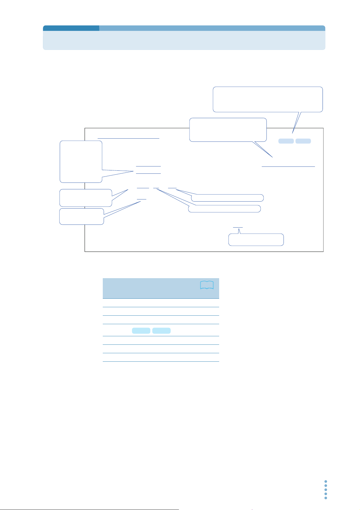
Command Description in This Manual
In this manual, commands are described in the following manner.
Commands that have these marks are affected
when an *RST or *RCL command is sent. The
settings for the command are changed to the values
that are shown in the “Default State” section.
The parameters are listed.
In this command, the parameter is numeric.
In addition to specifying the desired value,
CURR:PROT:OVER
The commands are
listed in the long form.
The lowercase
characters can be
omitted.
Sections that are
enclosed in braces ([ ])
can also be omitted.
The selectable range is given.
Optional symbols such as m
and µ can also be used.
The unit for the value
being set.
The unit can be omitted.
Sets the positive OCP’s current activation point.
Command [SOURce:]CURRent:PROTection[:LEVel]:OVER {<numeric>|MIN|MAX}
[SOURce:]CURRent:PROTection[:LEVel]:OVER?
Parameter Value:
Response
-1 % to 110 % of the rated output current
(The default value is 110 % of the rated output current.)
Unit: A
Returns the positive current activation point in <NR3> format.
you can specify the minimum or maximum
value.
Specify MAX to set the maximum value.
Specify MIN to set the minimum value.
* RCL* RST
References to command descriptions
Item
Command syntax 14
Parameters 17
Units 18
Default state
* RCL* RST
Queries 16
List of messages 87
List of errors 96
See
Page
81
The format of the value that is
returned when a query is sent.
PBZ_INTERFACE 19

4
IEEE 488.2 Common Commands
*CLS
See
See
p. 72
Command *CLS
Clears all event registers including the status byte, event status, and error queue.
*ESE
p. 76
Command *ESE <NR1>
Parameter Value: 0 to 255
Response Returns the value of the event status enable register in <NR1> format.
Sets the event status enable register that is counted by the event summary bit (ESB) of the status
byte.
*ESE?
An SCPI error (-222, “Data out of range”) occurs if the specified value is outside
the range.
Example When *ESE 16 is transmitted, bit 4 of the event status enable register is set. Each time
the execution error bit (bit 4) of the event status register is set, the summary bit (ESB) of
the status byte is set.
*ESR
See
p. 76
Command *ESR?
Response Returns the value of the event status register in <NR1> format and clears the register.
Queries the event status register. Registers that are read are cleared.
*IDN
Queries the model name, serial number, and firmware version of the PBZ.
Command *IDN?
Response The response to *IDN? is indicated below.
Example For a PBZ20-20 with serial number AB123456 and firmware version 1.00, *IDN? returns:
KIKUSUI,PBZ20-20,AB123456,1.00.
20 PBZ_INTERFACE

*OPC
IEEE 488.2 Common Commands
See
IEEE 488.2-1992
Section 10.18
Command *OPC
Response
*OPT
Command *OPT?
Response If the factory option LAN interface board is installed, "LAN" is returned. Returns “0” if no options are
*PSC
See
IEEE 488.2-1992
Section 10.25
Sets the OPC bit (bit 0) of the event status register when all the commands that are in standby have
been processed.
*OPC?
Returns “1” when all the commands that are in standby have been processed.
Queries the options that are installed in the PBZ.
installed.
When the result of rounding the specified value is a number other than zero, it is interpreted as one,
and this command sets the service request enable and event status enable registers to their initial
values when the PBZ restarts.
See
See
Command *PSC <NR1>
*PSC?
Parameter Value: -32767 to +32767
Response Returns “1” when the result of rounding the specified value is a number other than zero.
*RCL
Aborts measurement and loads the settings that have been saved to setup memory. This command
performs the same function as the MEM:SET:RCL command.
p. 81
For the commands that are affected by *RCL, see " Default State".”
Command *RCL <NR1>
Parameter Value: 0 to 9 Memory number
An SCPI error (-222, “Data out of range”) occurs if the specified value is outside
the range.
*RST
Aborts measurement and initializes the PBZ to the factory default settings.
p. 81
For the commands that are affected by *RST, see " Default State".”
Command *RST
PBZ_INTERFACE 21

IEEE 488.2 Common Commands
*SAV
Saves the current settings to setup memory. This command performs the same function as the
MEM:SET:SAV command.
See
p. 81
For the commands that are affected by *RCL, see " Default State".”
Command *SAV <NR1>
Parameter Value: 0 to 9 Memory number
*SRE
Sets the service request enable register.
The service request enable register can be used to select which summary messages in the status
byte register will perform service requests.
To clear the service request enable register, send *SRE 0. If the register is cleared, service requests
cannot be generated by status information.
An SCPI error (-222, “Data out of range”) occurs if the specified value is outside
the range.
See
Command *SRE <NR1>
*SRE?
Parameter Value: 0 to 255
An SCPI error (-222, “Data out of range”) occurs if the specified value is outside
the range.
Example Sending *SRE 8 sets bit 3 of the service request enable register. Each time the summary
bit (bit 3) of the QUEStionable status register in the status byte is set, a service request
message is generated.
Response Returns the value of the service request enable register in <NR1> format.
*STB
p. 74
Command *STB?
Response Returns the value of the status byte register and the MSS message (bit 6) in <NR1> format.
Queries the contents of the status byte register and the MSS (master summary status) message.
The response is the same as serial polling only with the exception that the MSS message appears in
place of the RQS message in bit 6.
*TRG
See
IEEE 488.2-1992
Section 10.37
Trigger command.
This is a substitute command for the IEEE 488.1 get message (Group Execute Trigger). If the PBZ is in
a state in which it does not accept triggers, an SCPI error (-211, “Trigger ignored”) occurs.
Command *TRG
22 PBZ_INTERFACE

*TST
IEEE 488.2 Common Commands
See
IEEE 488.2-1992
Section 10.38
Command *TST?
Response
*WAI
Command *WAI
Executes a self-test. You can query which error occurred by sending the SYST:ERR? command.
Returns “0” if no errors are detected. Returns the error code if an error is detected.
Prevents the PBZ from executing subsequent commands until all operations that are in standby
have completed.
PBZ_INTERFACE 23

5
Output Setting Commands
CV/CC Mode and Bipolar/Unipolar Mode
FUNC:MODE
Sets the CV/CC mode setting.
Command [SOURce:]FUNCtion:MODE {CC|CV}
[SOURce:]FUNCtion:MODE?
Parameter Value: CC CC mode
CV CV mode (default)
Response Returns the setting in <character> format in response to the FUNC:MODE? query.
FUNC:POL
Sets the bipolar/unipolar mode setting.
Command [SOURce:]FUNCtion:POLarity {BIPolar|UNIPolar}
[SOURce:]FUNCtion:POLarity?
Parameter Value: BIPolar Bipolar mode (default)
UNIPolar Unipolar mode
Response Returns the setting in <character> format in response to the FUNC:POL? query.
* RCL* RST
* RCL* RST
Selecting the Signal Source (Internal or External) and Setting the External Signal Source
FUNC:SOUR
Sets the signal source (internal, external, or both).
Command [SOURce:]FUNCtion:SOURce {INTernal|EXTernal|BOTH}
[SOURce:]FUNCtion:SOURce?
Parameter Value: INTernal Internal signal source (default)
EXTernal External signal source
BOTH Internal signal source and external signal source are added (ADD)
Response Returns the setting in <character> format in response to the FUNC:SOUR? query.
24 PBZ_INTERFACE
* RCL* RST

Output Setting Commands
FUNC:EXT:TERM
Selects the external signal source terminal.
Command [SOURce:]FUNCtion:EXTernal:TERMinal {BNC|J1|BOTH}
[SOURce:]FUNCtion:EXTernal:TERMinal?
Parameter Value: BNC BNC terminal (default)
J1 J1 connector
BOTH BNC terminal + J1 connector
Response Returns the setting in <character> format in response to the FUNC:EXT:TERM? query.
FUNC:EXT:CURR:GAIN
FUNC:EXT:VOLT:GAIN
Sets the gain of the external signal source BNC terminal input.
Command [SOURce:]FUNCtion:EXTernal:CURRent:GAIN {<numeric>|MIN|MAX}
[SOURce:]FUNCtion:EXTernal:VOLTage:GAIN {<numeric>|MIN|MAX}
Command [SOURce:]FUNCtion:EXTernal:CURRent:GAIN? [{MIN|MAX}]
[SOURce:]FUNCtion:EXTernal:VOLTage:GAIN? [{MIN|MAX}]
* RCL* RST
* RCL* RST
Parameter Value: PBZ20-20: 0 to 20 (CV or CC mode)
PBZ40-10: 0 to 40 (CV mode), 0 to 10 (CC mode)
PBZ60-6.7: 0 to 60 (CV mode), 0 to 6.7 (CC mode)
PBZ80-5: 0 to 80 (CV mode), 0 to 5 (CC mode)
(The default value is 0.)
Unit: A/V or V/V
Response Returns the gain in <NR3> format in response to the FUNC:EXT:CURR:GAIN? and
FUNC:EXT:VOLT:GAIN? queries.
PBZ_INTERFACE 25

Output Setting Commands
DC Signal Setting
VOLT
CURR
Sets the DC signal voltage and current.
Command [SOURce:]VOLTage[:LEVel][:IMMediate][:AMPLitude]
[SOURce:]CURRent[:LEVel][:IMMediate][:AMPLitude]
Command [SOURce:]VOLTage[:LEVel][:IMMediate][:AMPLitude]? [{MIN|MAX}]
[SOURce:]CURRent[:LEVel][:IMMediate][:AMPLitude]? [{MIN|MAX}]
Parameter Value: 0 % to 105 % of the rated output (The default value is 0 % of the rated output.)
Unit: V or A
* RCL* RST
{<numeric>|MIN|MAX}
{<numeric>|MIN|MAX}
Response Returns the voltage setting in <NR3> format in response to the VOLT? and CURR? queries.
VOLT:TRIG
CURR:TRIG
Sets the DC signal voltage and current when software triggers are received.
Command [SOURce:]VOLTage[:LEVel]:TRIGgered[:AMPLitude]
{<numeric>|MIN|MAX}
[SOURce:]CURRent[:LEVel]:TRIGgered[:AMPLitude]
{<numeric>|MIN|MAX}
Command [SOURce:]VOLTage[:LEVel]:TRIGgered[:AMPLitude]? [{MIN|MAX}]
[SOURce:]CURRent[:LEVel]:TRIGgered[:AMPLitude]? [{MIN|MAX}]
Parameter Value: 0 % to 105 % of the rated output
Unit: V or A
Response Returns the setting in <NR3> format in response to the VOLT:TRIG? and CURR:TRIG? queries.
26 PBZ_INTERFACE

AC Signal Command
Setting the AC Signal On/Off State
Output Setting Commands
AC:STAT
Sets the AC signal on/off state.
Command [SOURce:]AC:STATe {ON|OFF|1|0}
[SOURce:]AC:STATe?
Parameter Value: ON (1) On
OFF (0) Off (default)
Response Returns the AC signal on/off state in <NR1> format in response to the AC:STAT? query.
AC:STAT:TRIG
Sets the AC signal on/off state when software triggers are received.
Command [SOURce:]AC:STATe:TRIGgered {ON|OFF|1|0}
[SOURce:]AC:STATe:TRIGgered?
Parameter Value: ON (1) On
OFF (0) Off
Response Returns the AC signal on/off state in <NR1> format in response to the AC:STAT:TRIG? query.
* RCL* RST
Fixed Waveforms and User-defined Arbitrary Waveforms
FUNC
Selects the AC signal waveform.
Command [SOURce:]FUNCtion[:SHAPe][:IMMediate]
{SINusoid|SQUare|TRIangle|USER[1]..USER16}
[SOURce:]FUNCtion[:SHAPe][:IMMediate]?
Parameter Value: SINusoid Sine wave(default)
SQUare Square wave
TRIangle Triangle wave
USER[1] to USER16 User-defined arbitrary waveform (ARB1 to ARB16)
Response Returns the AC signal waveform type in <character> format in response to the FUNC? query.
* RCL* RST
PBZ_INTERFACE 27

Output Setting Commands
FUNC:TRIG
Selects the AC signal waveform when software triggers are received. The settable ranges for the
VOLT:TRIG, CURR:TRIG, VOLT:AC:TRIG, and CURR:AC:TRIG commands differ based on the FUNC:TRIG
setting. When this command is received, the PBZ first checks the relationship between these
settings. To ensure proper operation, send the FUNC:TRIG command first. When the FUNC:TRIG
command is received, the PBZ immediately sets the VOLT:TRIG, CURR:TRIG, VOLT:AC:TRIG, and
CURR:AC:TRIG values to the current values.
Command [SOURce:]FUNCtion[:SHAPe]:TRIGgered
[SOURce:]FUNCtion[:SHAPe]:TRIGgered?
Parameter Value: SINusoid Sine wave
Response Returns the AC signal waveform type in <character> format.
USER{[1]|2|...|16}:TITL
{SINusoid|SQUare|TRIangle|USER[1]..USER16}
SQUare Square wave
TRIangle Triangle wave
USER[1] to USER16 User-defined arbitrary waveform
Sets the user-defined arbitrary waveform’s title to a string of 15 characters in length. A space
character(0x20) is inserted automatically in case of a string of less than 15 characters in length. The
user-defined arbitrary waveforms are from USER1 to USER16. You can write USER1 as USER
(omitting the “1”).
Command [SOURce:]USER{[1]|2|..|16}:TITLe <“string”>
[SOURce:]USER{[1]|2|..|16}:TITLe?
Parameter Value: “string”
Example “My Waveform”
Response Returns the user-defined arbitrary waveform’s title in <“string”> format.
USER{[1]|2|...|16}:DATA:FORM:BORD
Sets the binary transmission data byte order of the user-defined arbitrary waveform. This command
cannot be used with the RS232C interface.
Command [SOURce:]USER{[1]|2|..|16}:DATA:FORMat:BORDer
{NORMal|SWAPped}
[SOURce:]USER{[1]|2|..|16}:DATA:FORMat:BORDer?
Parameter Value: NORMal Big endian (most significant byte first)
SWAPped Little endian (least significant byte first)
Response Returns the binary transmission data byte order of the user-defined arbitrary waveform in
<character> format.
28 PBZ_INTERFACE
Output Setting Commands
USER{[1]|2|...|16}:DATA
Sets the user-defined arbitrary waveform pattern. The user-defined arbitrary waveforms are from
USER1 to USER16. You can write USER1 as USER (omitting the “1”). This command cannot be used
with the RS232C interface or LAN interface.
To use the RS232C or LAN interface to set a user-defined arbitrary waveform pattern, use
USER{[1]|2|...|16}:DATA:VAL.
Command [SOURce:]USER{[1]|2|..|16}:DATA <arbitrary block data>
[SOURce:]USER{[1]|2|..|16}:DATA?
Parameter Value: Arbitrary block data (in binary block format)
Response Returns the user-defined arbitrary waveform pattern in <arbitrary block data> format.
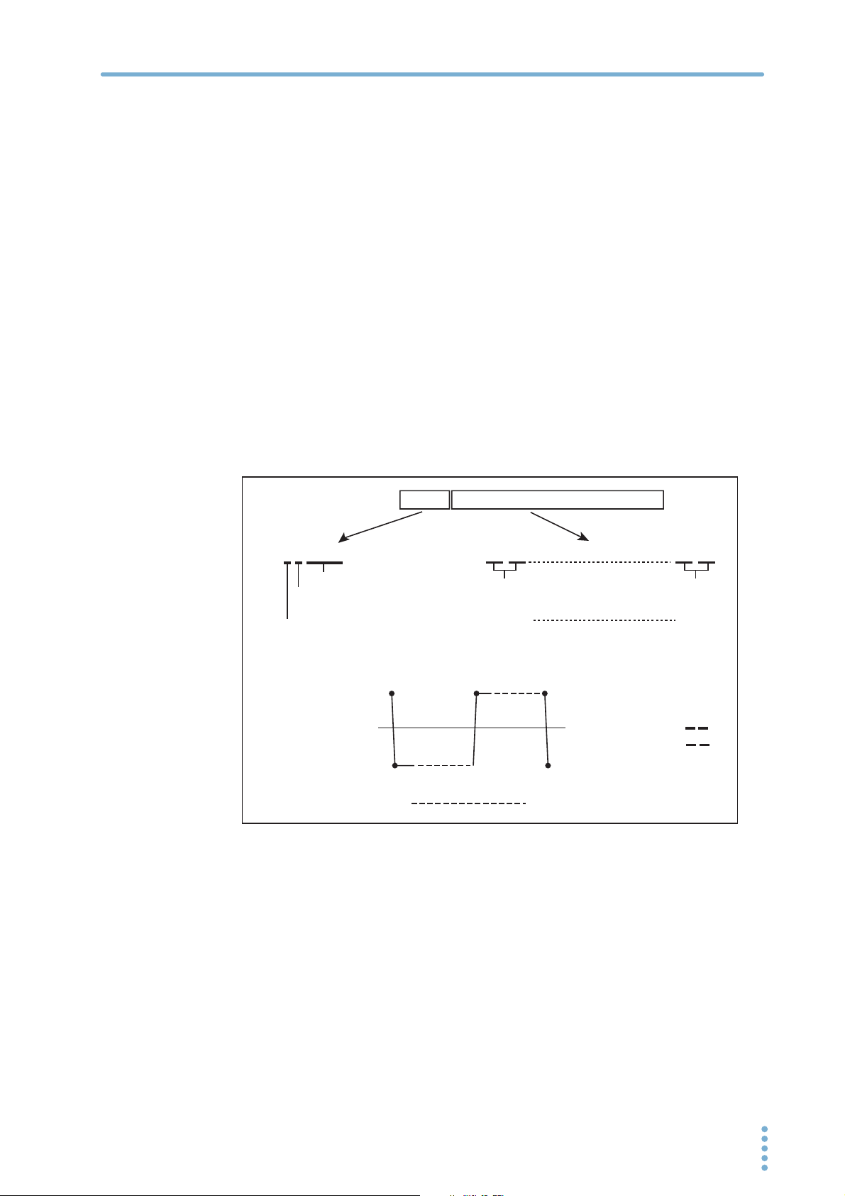
Binary block format data
Waveform data is represented as integer values that are composed of 2 bytes (16 bits) of binary data.
Therefore, the total number of bytes used for a waveform’s data is the number of data points in the
waveform times two. This number is always even. For example, if the number of waveform data points
is 1024, the total number of bytes in the waveform data is 2048.
Example
#42048
Number of digits that follow
(these represent the number of bytes)
Start of the data block
7FFF (H) 32767
Signed 16-bit
data
8000 (H) -32768
USER2:DATA #420487FFF8000...7FFF...7FFF8000
7FFF8000...7FFF...7FFF8000
Number of bytes that follow
Data points 0
2 bytes
Data points 0
(2048 bytes)
Order setting for the pairs of
bytes for each data point
USER2:DATA:FORM:BORD
NORM:
SWAP:
1024
2 bytes
1024
7FFF
FF7F
PBZ_INTERFACE 29

Output Setting Commands
USER{[1]|2|...|16}:DATA:VAL
Sets the waveform data relative to the waveform peak value for any of 1024 divisions of one period
of a user-defined arbitrary waveform. These waveform divisions are referred to as “addresses.” The
user-defined arbitrary waveforms are from USER1 to USER16. You can write USER1 as USER
(omitting the “1”).
Command [SOURce:]USER{[1]|2|..|16}:DATA:VALue <addr_NR1>,<data_NR1>
[SOURce:]USER{[1]|2|..|16}:DATA:VALue? <addr_NR1>
Parameter <addr_NR1>Address
Value: 0 to 1 023
<data_NR1>Waveform data
Value: -32 768 to +32 767
Example USER10:DATA:VAL 0,32767
Sets address 0 of the user-defined arbitrary waveform pattern to 32767.
To enter data for a square wave, set addresses 0 to 511 to +32767, and set addresses 512
to 1023 to -32768.
Response Returns the value at an address in a user-defined arbitrary waveform pattern in <NR1> format.
Signal Amplitude, Frequency, and Start Phase, and Square Wave Duty Cycle
VOLT:AC
Sets the AC signal voltage.
Command [SOURce:]VOLTage:AC[:IMMediate][:AMPLitude]
{<numeric>|MIN|MAX}
[SOURce:]VOLTage:AC[:IMMediate][:AMPLitude]? [{MIN|MAX}]
Parameter Value: 0 % to 105 % of the rated output voltage
(The default value is 0 % of the rated output voltage.)
Unit: VPP
Response Returns the setting in <NR3> format in response to the VOLT:AC? query.
CURR:AC
Sets the AC signal current.
Command [SOURce:]CURRent:AC[:IMMediate][:AMPLitude]
{<numeric>|MIN|MAX}
[SOURce:]CURRent:AC[:IMMediate][:AMPLitude]? [{MIN|MAX}]
* RCL* RST
* RCL* RST
Parameter Value: 0 % to 105 % of the rated output
(The default value is 0 % of the rated output current.)
Unit: APP
Response Returns the setting in <NR3> format in response to the CURR:AC? query.
30 PBZ_INTERFACE
 Loading...