

Kikusui PAX35-10, PAX35-20, PAX35-30 Operation Manual
Part No. Z1-002-522, IB003105
Sep. 2009
OPERATION MANUAL
PROGRAMMABLE DC POWER SUPPLY
PAX Series
PAX35-10
PAX35-20
PAX35-30

Use of Operation Manual
Please read through and understand this Operation Manual before operating the product. After reading,
always keep the manual nearby so that you may refer to it as needed. When moving the product to another
location, be sure to bring the manual as well.
If you find any incorrectly arranged or missing pages in this manual, they will be replaced. If the manual
gets lost or soiled, a new copy can be provided for a fee. In either case, please contact Kikusui distributor/
agent, and provide the “Kikusui Part No.” given on the cover.
This manual has been prepared with the utmost care; however, if you have any questions, or note any errors
or omissions, please contact Kikusui distributor/agent.
Microsoft and Windows are registered trademarks of Microsoft Corp. in the United States and/or other
countries.
All other company names and product names used in this document are trademarks or registered
trademarks of the respective company.
Reproduction and reprinting of this operation manual, whole or partially, without our permission is
prohibited.
Both unit specifications and manual contents are subject to change without notice.
Copyright© 2001-2009 Kikusui Electronics Corporation

Request to Users
This products must be used only by qualified personnel who understand the contents of this
operation manual. If it is handled by disqualified personnels, electrical hazards may result. Be
sure to handle it under supervision of qualified personnel (those who have electrical
knowledge).
If any abnormality or failure was detected in the products, stop using it immediately and
contact your Kikusui distributor or agent.
Installation
• Be sure the environmental condition where the products to be installed meets all
requirements listed in the operation manual.
• To prevent electric shock, connect the ground terminal to electrical ground (safety ground).
• Connect the product to the specified AC power source with the AC power cable provided.
• For output wiring or load cables, use connection cables with larger current capacity.
Maintenance and inspection
• To prevent electric shock, be absolutely sure to unplug or stop applying power before
performing maintenance or inspection.
• Make sure the AC input voltage setting and the fuse ratings are satisfied and that there is no
abnormality in the AC power cable.
• Do not remove the cover when performing maintenance or inspection. There are parts
inside the product which may cause physical hazards. Consult your Kikusui distributor or
agent before uncover the products in case if it is so necessary.
• To maintain performance and safe operation of the product, it is recommend to conduct a
periodic maintenance, inspection, cleaning, and calibration.
Relocation
• Disconnect all cables when relocate the product.
• Use two or more persons when relocate the product which weights more than 20 kg. The
weight of the products can be found in this operation manual.
• Be careful of harming protruded parts of the products such as output terminals, terminal
boards or heatsinks when moving.
• Use extra precautions such as using more people when relocating into or out of present
locations including inclines or steps. Also handle carefully when relocating tall products as
they can fall over easily.
• Be sure the operation manual are included whenever the product is moved, relocated or
possession is passed to another party.


ROM Version Number
This manual is applicable to the power supplies which
have the following version of ROM (read only memory).
2.0*
(*denotes 0 to 9.)
When making any inquires on your power supply,
please indicate the following:
• Model No.
• ROM Version No.
• Serial No.
To find the ROM Version No., please refer to Section 2.3 "Power Turn-on Check"
under Chaper 2 "PRECAUTIOS AND PREPARATIVE PROCEDURES." The Serial No. is indicated on the rear panel.
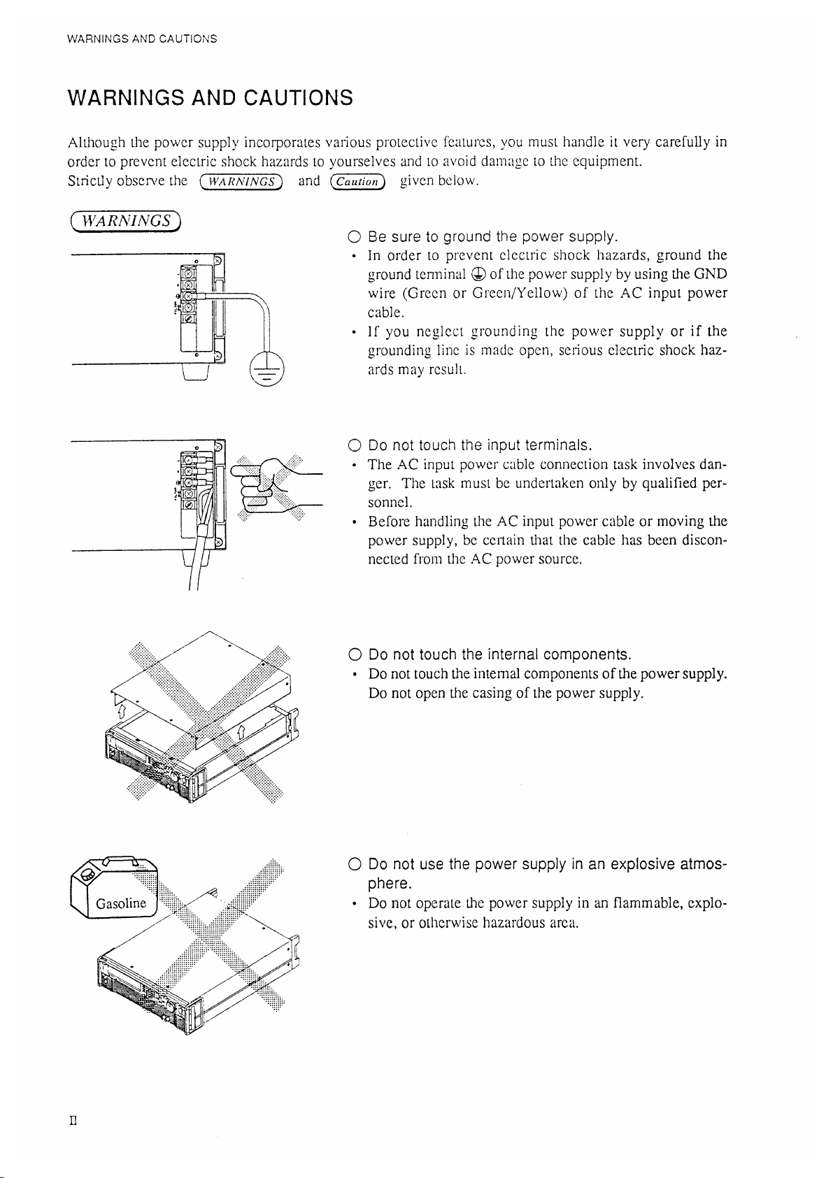
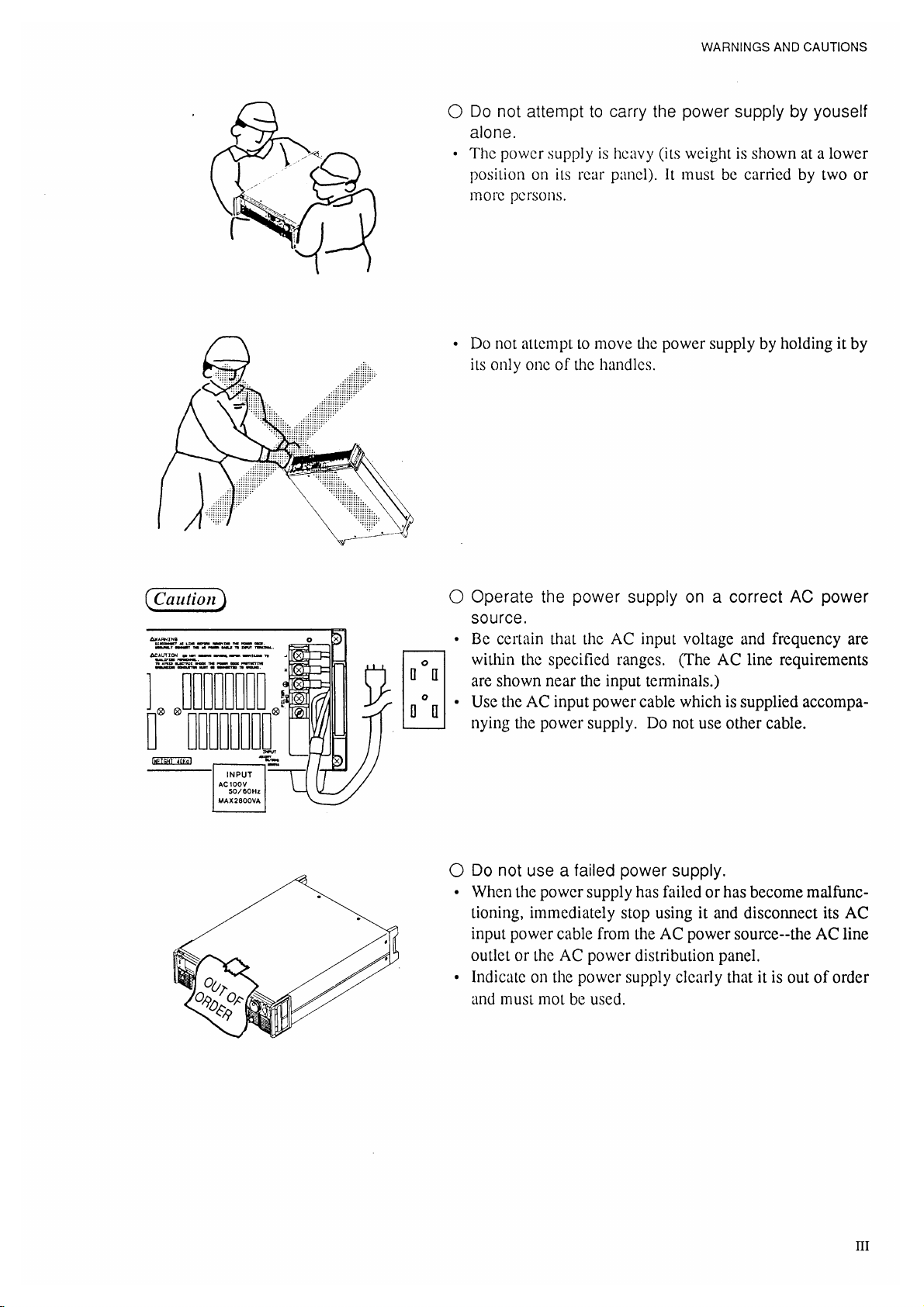
WARNINGS
and
Caution
Before start using the power supply and during using it, be sure to read and strictly
observe the instructions given in the following:
"WARNINGS AND CAUTIONS" (next page)
Chapter 1 "GENERAL"
Chapter 2 "PRECAUTIONS AND PREPARATIVE PROCEDURES"
I


COMPOSITION OF THE OPERATION MANUAL
COMPOSITION OF THE OPERATION MANUAL
This operation manual is composed of seven chapters and appendices as follows:
Chapter 1. GENERAL
Introduces an outline and features of the power supply.
Chapter 2. PRECAUTIONS AND PREPARATIVE PROCEDURES
Elaborates procedures for installation, AC input power cable connection, power-on test, operating mode selection, and load connection.
Chapter 3. OPERATING METHOD
The former half of this chapter introduces the names and fucntions of keys, indicators and
other panel items, and the basic operating method of the power supply; the latter half describes the procedures for sequence operation and applied types of operation.
Chapter 4. REMOTE PROGRAMMING
Elaborates the method to remote-control the power supply via an interface board (optional)
from an external device.
Chapter 5. PANEL DESCRIPTION
Introduces the names of and describes the functions of the switches and other items of the
front and rear panels.
Chapter 6. MAINTENANCE AND CALIBRATION
Elaborates the maintenance, inspection, and calibration methods.
Chapter 7. SPECIFICATIONS
Gives tables of electrical specifications, mechanical specifications, accessories, and optional
items.
APPENDICES
VIII
Provides an error message table, a troubleshooting chart, a table of factory-defaults, a nemu
configuration chart, sequence coding sheets. and a table of ID codes and offset calibration
values.

TABLE OF CONTENTS
TABLE OF CONTENTS
PAGE
WARNINGS AND CAUTIONS ..................................................................................................... II
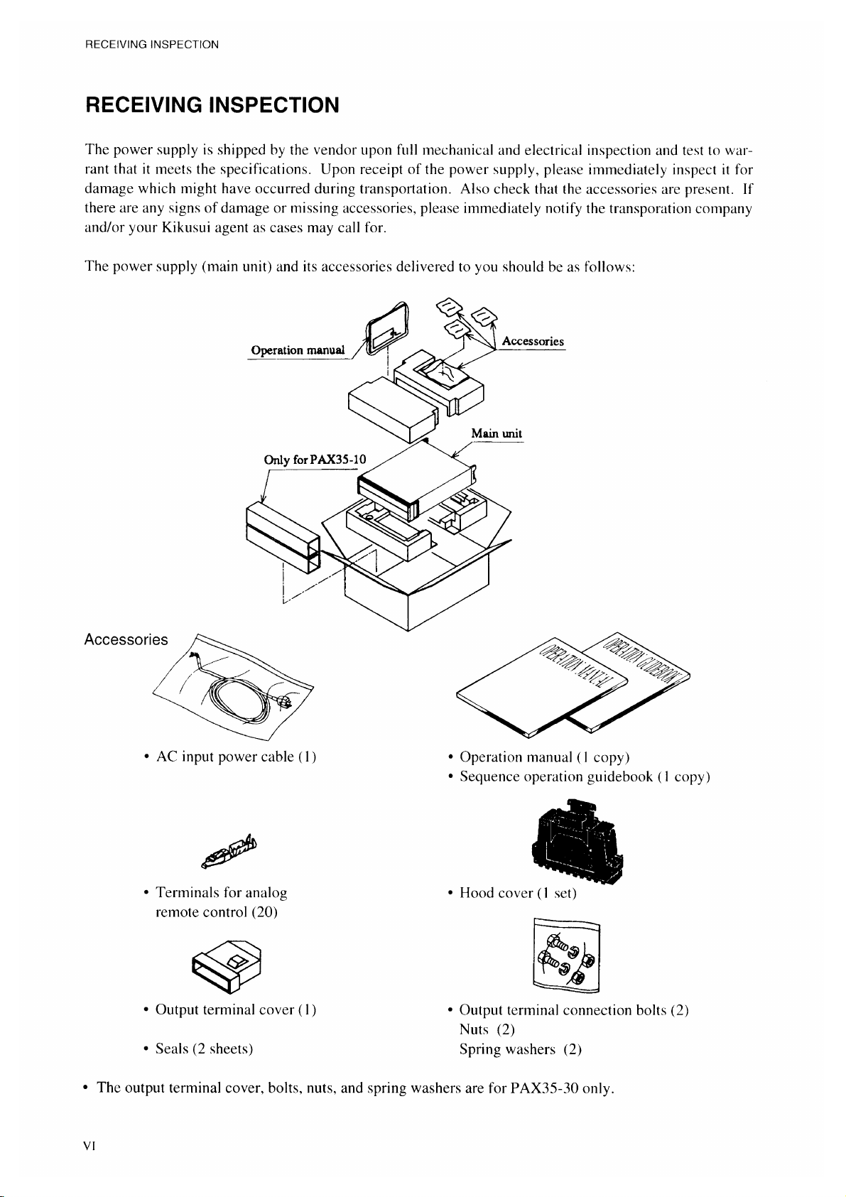
RECEIVING INSPECTION ........................................................................................................... VI
PACKAGING FOR RE-SHIPMENT ............................................................................................. VII
COMPOSITION OF THE OPERATION MANUAL ..................................................................... VIII
Chapter 1. GENERAL ..................................................................................................... 1-1
1.1 Outline .............................................................................................................. 1-2
1.2 Features ............................................................................................................. 1-3
Chapter 2. PRECAUTIONS AND PREPARATIVE PROCEDURE .................................. 2-1
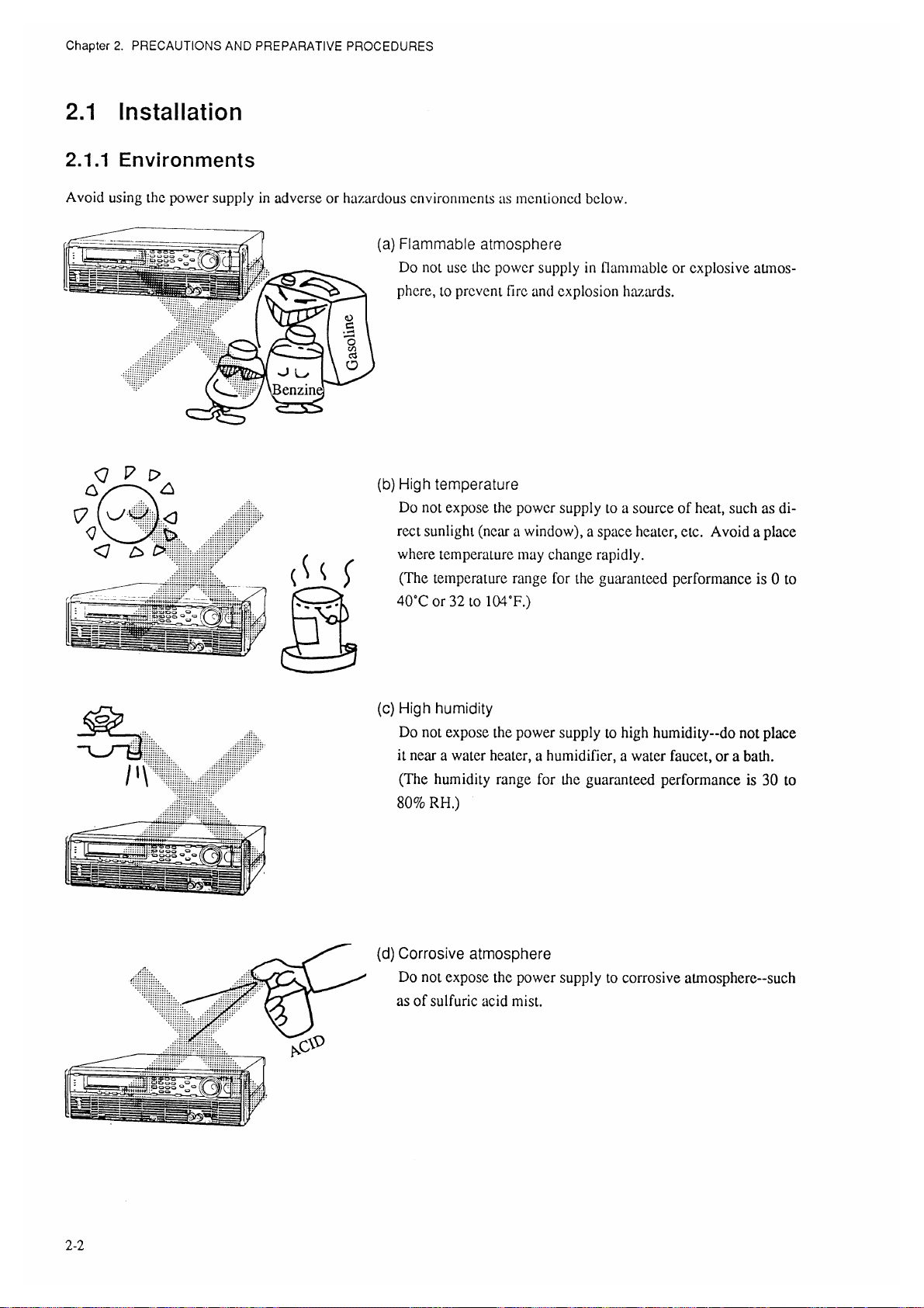
2.1 Installation ........................................................................................................ 2-2
2.1.1 Environments ......................................................................................... 2-2
2.1.2 Precautions for Moving the Power Supply ............................................ 2-4
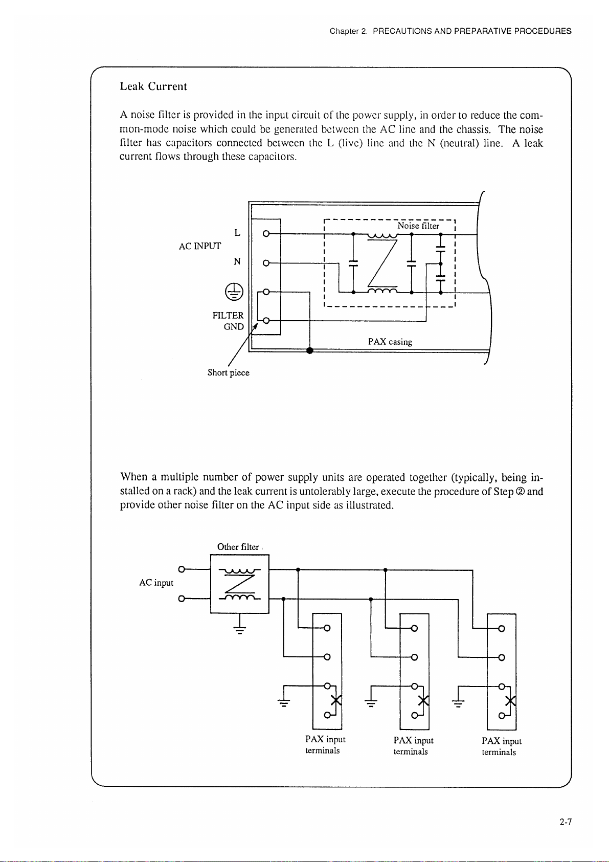
2.2 Connecting the AC Input Power Cable ............................................................ 2-5
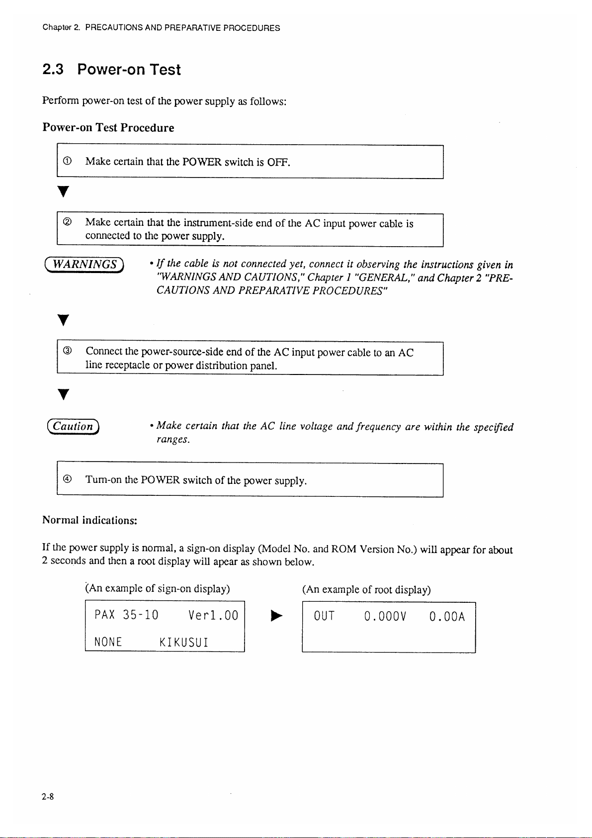
2.3 Power-on Test ................................................................................................... 2-8
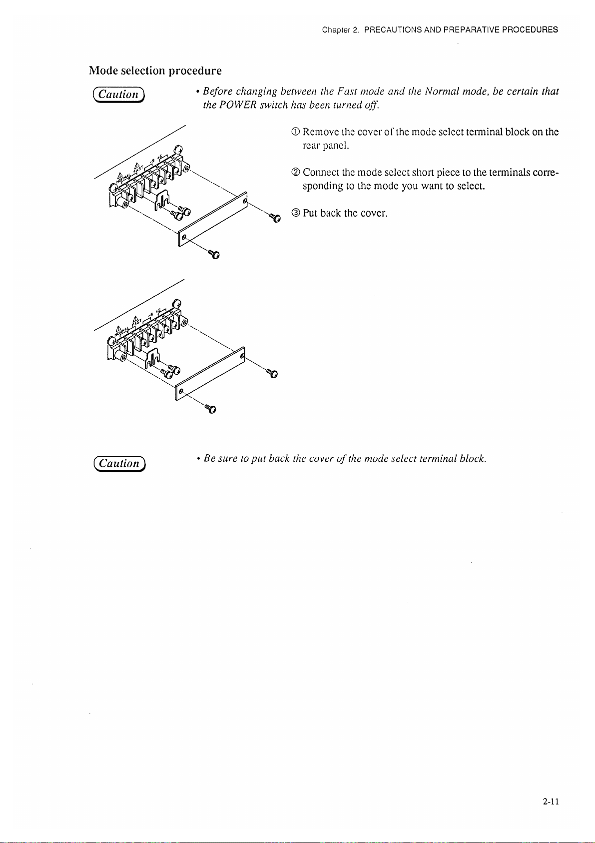
2.4 Operating Mode Selection ................................................................................ 2-10
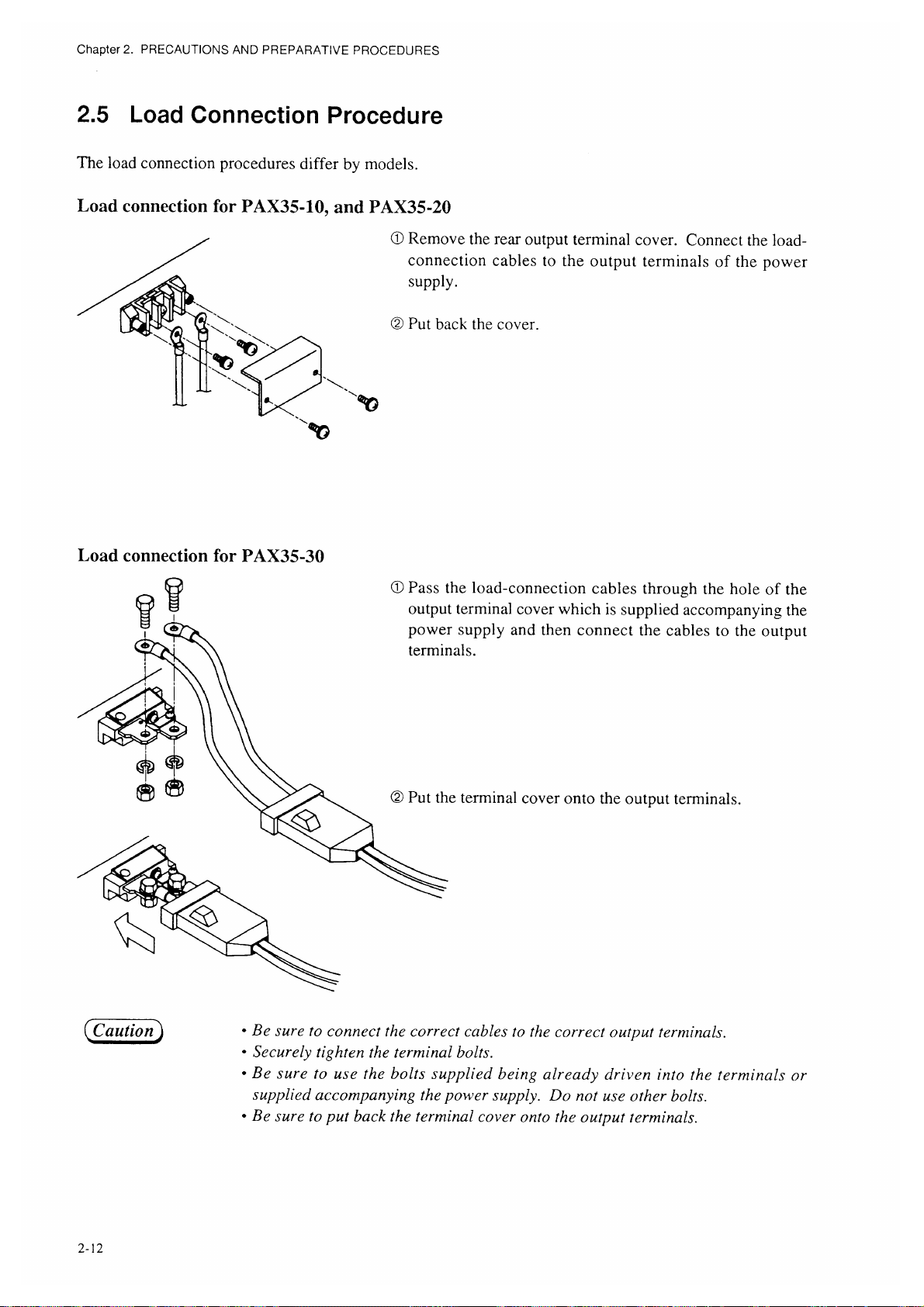
2.5 Load Connection Procedure ............................................................................. 2-12
2.5.1 Notes for Particular Types of Loads ...................................................... 2-13
2.5.2 Notes for Load Connection .................................................................... 2-14
Chapter 3. OPERATING METHOD................................................................................. 3-1
3.1 Description of Front and Rear Panels ............................................................... 3-3
3.1.1 Front Panel ............................................................................................. 3-3
3.1.2 Rear Panel .............................................................................................. 3-3
3.2 Basic Operating Method 1 ................................................................................ 3-5
3.2.1 Turning ON/OFF the POWER Switch ................................................... 3-5
3.2.2 Basic Panel Operating Method ............................................................... 3-6
3.2.3 Voltage/Current Settings and Output ON/OFF ...................................... 3-10
3.2.4 Fine Setting of Output Voltage or Current ............................................. 3-13
3.2.5 Setting of Protective Actions.................................................................. 3-14
3.2.6 To Reset from Protective Alarm Status .................................................. 3-18
3.3 Basic Operating Method 2 ................................................................................ 3-20
3.3.1 Remote Sensing Function....................................................................... 3-20
3.3.2 Memory Function ................................................................................... 3-21
3.3.3 Setup Function ........................................................................................ 3-23
3.3.4 Keylock Function ................................................................................... 3-29
3.3.5 Setting the Click Resolution ................................................................... 3-30
3.3.6 Setting the Rise/Fall Time ...................................................................... 3-31
3.3.7 Displaying the Interface Status .............................................................. 3-32
3.4 Sequence Operation .......................................................................................... 3-33
3.4.1 Description of Sequence Operation ........................................................ 3-33
3.4.2 Outline of Settings for Operation ........................................................... 3-39
3.4.3 Procedures for Sequence Operation ....................................................... 3-40
3.5 Applied Types of Operation ............................................................................. 3-54
3.5.1 Configuration ......................................................................................... 3-54
3.5.2 Analog Remote Control ......................................................................... 3-65
IX

TABLE OF CONTENTS
Chapter 4. REMOTE PROGRAMMING .......................................................................... 4-1
4.1 Initial Setting of Interface ................................................................................. 4-3
4.1.1 GPIB Interface ........................................................................................ 4-3
4.1.2 RS-232C Interface .................................................................................. 4-4
4.1.3 MCB Interface ........................................................................................ 4-5
4.2 Programming Format ........................................................................................ 4-6
4.2.1 Commands .............................................................................................. 4-6
4.2.2 Response Message .................................................................................. 4-7
4.2.3 Acknowledge Message (RS-232C) ........................................................ 4-7
4.2.4 Flow Control (RS-232C) ........................................................................ 4-8
4.3 Description of Commands ................................................................................ 4-9
4.3.1 Terminology ........................................................................................... 4-9
4.3.2 Structures of Commands ........................................................................ 4-10
4.4 Bit Assignment of Registers ............................................................................. 4-25
4.5 Relationships Among SRQ, Status Bytes, and Registers ................................. 4-28
4.6 Table of Error Codes ........................................................................................ 4-29
4.7 Examples of Remote Programming .................................................................. 4-30
4.7.1 Initializing the Interface Board .............................................................. 4-30
4.7.2 Examples of Application Programs ........................................................ 4-31
4.7.3 Table of Command Headers ................................................................... 4-45
Chapter 5. PANEL DESCRIPTION ................................................................................. 5-1
5.1 Front Panel ........................................................................................................ 5-2
5.2 Rear Panel ......................................................................................................... 5-6
Chapter 6. MAINTENANCE AND CALIBRATION ........................................................... 6-1
6.1 Maintenance and Inspection ............................................................................. 6-2
6.2 Calibration ........................................................................................................ 6-4
6.2.1 Preparation ............................................................................................. 6-4
6.2.2 Calibration Instruments .......................................................................... 6-4
6.2.3 Calibration Setups .................................................................................. 6-4
6.2.4 Calibration Procedures ........................................................................... 6-5
Chapter 7. SPECIFICATIONS ......................................................................................... 7-1
7.1 Electrical Specifications ................................................................................... 7-2
7.2 Dimensions and Weights .................................................................................. 7-11
7.3 Accessories ....................................................................................................... 7-12
7.4 Optional Items .................................................................................................. 7-13
APPENDICES .................................................................................................................. A-1
Appendix 1. Table of Error Messages ....................................................................... A-2
Appendix 2. Troubleshooting Chart .......................................................................... A-5
Appendix 3. Table of Factory-Defaults ..................................................................... A-7
Appendix 4. Menu Charts .......................................................................................... A-8
Appendix 5. Sequence Coding Sheets ....................................................................... A-13
Appendix 6. Table of ID Codes and Offset Calibration Values ................................ A-16
INDEX .............................................................................................................................. I-1
X


Chapter 1. GENERAL
1.2 Features
Each PAX Power Supply is incorporated or can be optionally incorporated with the various advantageous
features as follows:
(1) Two operating modes
The power supply allows you to select one of the following two types of operating modes.
μ
(a) Fast mode: For rapid rise up and fall down (Selectable for 50
(b) Normal mode: For stable operation with low ripple noise (Since no switching actions are in-
volved, the output noise is small.)
(2) Sequence control of output
You can enter sequence control patterns from the local panel or from a personal computer via GPIB
or other interface bus and store them as sequence files on the internal memory. The stored files can be
recalled locally from the front panel or remotely from the host controller via the interface bus.
Control sequences can be programmed in either one of the following two types:
s, 500μs or 5ms)
(a) Fast speed sequence: You can program sequences with minimum 100
(b) Normal speed sequence: You can program sequences with a ramp waveform per step.
μ
s per step.
(3) Various interface boards (optional)
The power supply can be controlled over a GPIB, RS-232C, or MCB interface bus. This feature, as
combined with the programmed sequence control function, allows you a high flexibility of power
supply system configuration.
The MCB is a unique interface developed by Kikusui. It allows you to control up-to-fifteen instruments (power supplies and electronic load devices) in an on-line mode over a standard interface
system (GPIB or RS-232C).
(4) Ease of operation
Numeric entry keypad, arrow keys, and JOG/SHUTTLE dials are provided on the front panel,to
facilitate entry of numerical values and selection of menu items.
Operation SETUPs of the power supply can be stored in memory and be recalled whenever you need
them. Up to four different types of voltage/current settings can be programmed and stored in different locations of memory. This feature is convenient especially when you want to repeat tests with the
same setup of the power supply.
(5) A large backlight LCD
The power supply has a large backlighted-type LCD (liquid crystal display), which displays output
voltage and current settings, readbacks, and other operation data.
(6) Ease of calibration
The power supply can be calibrated easily with the keys on the front panel, without requiring any
sophisticated calibration procedures (but requiring a digital voltmeter and a shunt resistor).
1-3

Chapter 1. GENERAL
(7) Various protective provisions
The power supply incorporates provisions for double-protection with software protectors and hardware protectors against output overvoltage (OVP) and overcurrent (OCP). The software protectors
provide an automatic function that the power supply automatically sets the limit values as you specify
a tolerance of overvoltage or overcurrent in percentage. They also allows you to select either
"POWER switch OFF" or "OUTPUT OFF" for protection when a protector has tripped and the power
supply has fallen into an alarm state.
The power supply also incorporates an overtemperature protector and an input overcurrent protector.
Thus, the various provisions are incorporated to protect the power supply itself and its load.
(8) Analog remote control
You can remote-control the output voltage or current with an external voltage signal or resistance.
You also can remote-control turning OFF of the POWER switch and turning ON/OFF of the output.
The power supply provides various status signals.
(9) Exclusive remote controller (optional)
The remote controller allows you to extend virtually the front panel to a remote position convenient
for you. The control functions of the remote controller are identical with those of the front panel of
the power supply.
1-4
 Loading...