

Kikusui PAV160-1.3, PAV60-3.5, PAV20-10, PAV650-0.32, PAV100-2 User Manual
...
200 W type
PAV10-20 PAV160-1.3
PAV20-10 PAV320-0.65
PAV36-6 PAV650-0.32
PAV60-3.5
PAV100-2
400 W type
PAV10-40 PAV160-2.6
PAV20-20 PAV320-1.3
PAV36-12 PAV650-0.64
PAV60-7
PAV100-4
600 W type
PAV10-60 PAV160-4
PAV20-30 PAV320-2
PAV36-18 PAV650-1
PAV60-10
PAV100-6
800 W type
PAV10-72 PAV160-5
PAV20-40 PAV320-2.5
PAV36-24 PAV650-1.25
PAV60-14
PAV100-8
Regulated DC Power Supply
PAV Series
LAN Interface Manual
art No. IB029782
P
Mar. 2016
1. Description 4
2. Network Connection 6
3. Webpage 18
4. Specifications 33
Appendix 35

The manuals are intended for users of the PAV series and
About PAV manual
Notations used in this manual
their instructors. Explanations are given under the presumption that the reader has knowledge of power supplies.
Manual construction
•Setup Guide
This manual is intended for first-time users of the product. It
gives an overview of the product, connecting procedures,
safety precautions, etc. Please read this manual before you
operate the product.
• Quick Reference
The quick reference briefly explains the control panel and
the basic operation of it.
• Safety Information
This document contains general safety precautions for this
product. Keep them in mind and make sure to observe
them.
• User’s manual (PDF)
This manual is intended for first-time users of this product. It
provides an overview of the product, notes on usage, and
specifications. It also explains how to connect the product,
configure the product, operate the product, perform maintenance on the product, and so on.
• USB/RS232/RS485 Communication Interface Manual
(PDF)
This manual explains how to control the product remotely
using SCPI commands.
The interface manual is written for readers with sufficient
basic knowledge of how to control measuring instruments
using a PC.
• LAN Interface Manual (PDF)
This manual explains how to control the product remotely
for users of the PAV series with the optional LAN interface.
The interface manual is written for readers with sufficient
basic knowledge of how to control measuring instruments
using a PC.
• The PAV series is categorized into four types according to
the output capacity. This manual contains sections that
describe each type separately or several types collectively.
The type categories are provided on the front cover.
• The PAV series with a LAN interface is also referred to as
the “PAV with LAN” or simply PAV.
• The term “PC” is used to refer generally to both personal
computers and workstations.
• The following markings are used in the explanations in this
manual.
Indicates information that you should know.
Copyright© 2015 Kikusui Electronics Corporation
You can download the most recent version of these manuals
from the Kikusui Electronics Corporation website (http://
www.kikusui.co.jp/en/download/).
You can view the PDF files using Adobe Reader 10 or later.
Before reading this manual
First read the User’s Manual, which includes information on
the product's hardware, to avoid connecting or operating the
product incorrectly.
Trademarks
Microsoft, Windows, and Internet Explorer are registered
trademarks or trademarks of Microsoft Corporation in the
United States and/or other countries.
All company names and product names used in this manual
are trademarks or registered trademarks of their respective
companies.
Copyrights
The contents of this manual may not be reproduced, in whole
or in part, without the prior consent of the copyright holder.
The specifications of this product and the contents of this manual are subject to change without prior notice.
2 PAV L AN

Contents
About PAV manual ...................................2
Notations used in this manual ................. 2
Contents ..................................................... 3
1 Description ................................................4
Features........................................................ 4
2 Network Connection ........................6
LAN port ........................................................ 6
LAN configuration.......................................... 7
Network types......................................... 7
Selecting the LAN interface.................... 8
Control functions that can be used
simultaneously with LAN ...................... 10
LAN Connection.......................................... 11
Starting a connection............................ 11
Displaying and changing the IP
address ............................................. 11
Checking the host name....................... 13
Displaying the MAC address................ 13
LAN reset ............................................. 14
RS485 Multi-Drop Connection .................... 15
Description ........................................... 15
LAN connections .................................. 16
RS485 connection ................................ 17
Socket Communication .............................. 39
Communication using sockets............. 39
WAN Connection........................................ 41
LAN Commands......................................... 42
Global Commands for Multi-Drop
Connection . .............................................. 43
Selecting the PAV ............................... 43
Responses to global commands ......... 43
Index....................................................... 44
3Webpage ....................................................18
Home Page ................................................. 18
Opening the Home page ...................... 18
Description of the Home page.............. 19
Logging In and Logging Out........................ 20
Logging in............................................. 20
Logging Out.......................................... 21
DC Power Page .......................................... 22
Output tab............................................. 22
Protection tab ....................................... 24
System tab ........................................... 25
Utility tab............................................... 26
LAN Page.................................................... 27
Configure tab........................................ 27
Advanced tab ....................................... 30
Users tab.............................................. 31
Help Page ................................................... 32
4 Specifications .......................................33
Appendix
Troubleshooting .......................................... 35
Driver Software ........................................... 37
Control using a VISA driver.................. 37
Control using an IVI driver.................... 38
PAV L AN 3

1
Description
The local area network (LAN) option can be used to perform remote control, measurement,
and status check on the PAV series.
The PAV can be controlled from a PC web browser through the web interface embedded in
the PAV.
Automatic control and measurement applications can be created using the standard network
protocol and measurement commands.
Features
Standard TCP/IP network communication
• LAN (local area network)
• WAN (wide area network)
• Communication with remote locations using the Internet
Webpage
• Network communication configuration
• Controlling and reading the PAV output and status from a GUI screen.
• Multi-user control and security settings to eliminate dangerous connection procedures
• Password for webpage protection
LAN protocol
• Supports VISA drivers, TCP socket, and UDP socket
• Supports VXI-11 discovery and Ping server
• LAN status indicator LED that lights when a network connection is established
• Simple creation of original auto control programs
Remote programming function
• Standard SCPI command language
• Supports VISA drivers and all test and measurement utilities
• TCP socket and UDP socket support PLCs, Linux, and other non-VISA controllers.
4 PAV LAN

1. Description Features
Front panel
• IP address and MAC address can be verified from the front panel.
• IP address can be assigned from the front panel.
• LAN reset can be performed from the front panel.
• Users can remotely control the blinking of the front panel display to identify which PAV is
being controlled in a rack.
Rear panel
• Equipped with an Ethernet RJ-45 port (standard 8-pin jack port for LAN)
• The RJ-45 port is equipped with a link LED and activity LED.
• The LAN status indicator LED on the rear panel shows the LAN communication status.
The LED can be controlled to blink to identify which PAV is being controlled.
RS485 multi-drop connection
• Up to 30 PAVs can be connected using the included RS485 link cables.
• All the PAVs in a RS485 multi-drop connection can be controlled using a single IP
address.
• PAVs in a RS485 multi-drop connection do not require the LAN option (except the master unit).
PAV L AN 5
2
1
2
3
4
Network Connection
This chapter describes the LAN port, LAN configuration, and RS485 multi-drop connection.
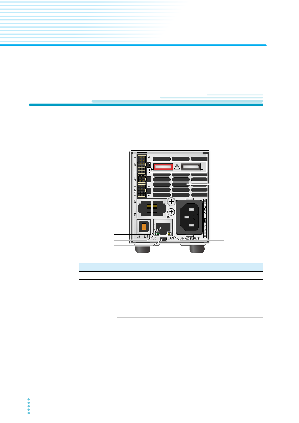
LAN port
The LAN port is on the rear panel. The following figure is for the 10 V to 100 V rated output
voltage model, but the LAN port is in the same location on the 160 V to 650 V rated output
voltage model.
No. Name Function
1 LAN port RJ-45 port for LAN connection.
2 Link LED
3 Activity LED
Normal operation
LAN sta-
4
tus indicator LED
1 You can use the identification function by accessing the webpage from a PC or the like or by
sending an SCPI command. When used, this LED blinks in sync with the front panel display.
This function is useful to identify which PAV you are controlling when there are several PAVs
mounted in the rack. If the PAVs are connected in a multi-drop configuration, only the LED of
the PAV with LAN (master unit) blinks.
2 To stop this blinking, click Blink Identify (p.22) on the webpage, send an SCPI command
(p.42), or turn or press the setting knob of the front panel.
6 PAV LAN
PAV identification
LAN fault
Green solid: When the PAV is connected to LAN.
Orange blinking: When a message packet is
detected.
Green solid: When the PAV can connect to LAN.
Green blinking
Red solid:
When the PAV is not in LAN remote mode, when a
LAN connection failed to be completed, or when the
LAN connection is disconnected.
1,2
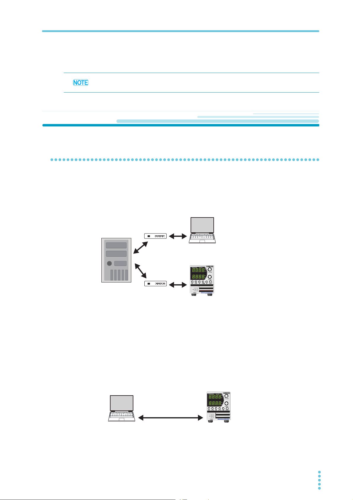
2. Network Connection LAN configuration
Ethernet hubNetwork
Server
Category 5 cable
Open the webpage on the PC,
or send an SCPI command.
PAV with LAN
Assign the IP address using a DHCP server
Category 5 cable
(straight or crossover cable)
IP address is automatically assigned.
(169.254.xxx.xxx)
Open the webpage on the PC,
or send an SCPI command.
PAV with LAN
LAN cable
Prepare a category 5 or better straight or crossover LAN cable.
The RS485 link cable included with the PAV cannot be used for LAN connection.
LAN configuration
Network types
Network connection using a server
This is the typical network connection. A LAN is operated with a server under the management of network administrators. The server assigns an IP address and other LAN parameters
to the PAV.
or a fixed IP address to the PAV.
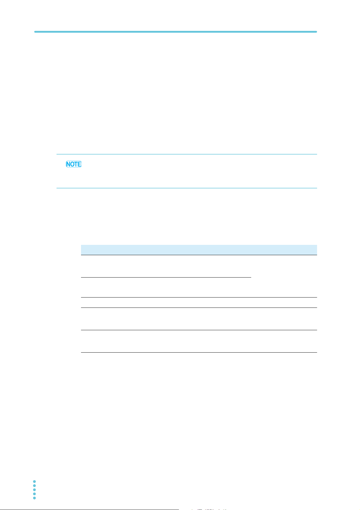
P2P (peer-to-peer) network connection
This is a connection where the PAV and the PC are connected directly. The PC only connects
to the PAV, not to any other network.
In the factory default setting, the PAV automatically assigns its own IP address and other LAN
parameters. To return to the default settings, perform a LAN reset (p.14). In addition, if the PC
is configured for automatic IP address assignment, the PAV assigns an IP address to the PC.
For details on IP addresses, see “Displaying and changing the IP address .” (p.11).
The PC is not connected to another network.
PAV L AN 7

LAN configuration 2. Network Connection
Interface
Address
Baud Rate
Language
IP Address
MAC Address
LAN Reset
RS232
RS485
USB
LAN
1...31
1200...
SCPI
IP-1...IP-4
MAC-1...MAC-6
Reset
nnnn
nnnn
Parameter
1200, 2400, 4800, 9600, 19200, 38400, 57600
PAG
Adr
INtF
232
485
USb
LAn
SCPI
PAG
bAUd
LANG
IP
IP1
...
IP4
MAC
MA1
...
MA6
rSt rSt
Legend
Move: Turn the VOLTAGE knob
Move: Turn the CURRENT knob.
CURRENT
Press the knob.
VOLTAGE
Enter:
Subsystem (first menu level)
Function (second menu level)
Parameter (third menu level)
Subsystem Function
Selecting the LAN interface
Use the REM menu to select the LAN interface. This menu is also used to set the IP address,
MAC address and perform LAN reset.
REM menu structure
REM
Enter: Press the CURRENT knob.
8 PAV LAN

2. Network Connection LAN configuration
Subsystem and function
The subsystem and function correspond to first and second menu levels.
Subsystem Function
item Panel display item Panel display
Interface INtF
Address Adr
Baudrate
Command language LANG
IP address
MAC address
LAN reset
3
5
5
5
bAUd
IP
MAC
rSt
1
RS232
RS485 485
USB USb
2
LAN
1 to 31
1
6
1200 to 57600
1
9600
1
SCPI
4
PAG
IP1 to IP4
MAC1 to MAC6
Reset
232
LAn
1 to 31
1200 to 57.6
SCPI
PAG
IP1 to IP4
MA1 to MA6
rSt
1 Factory default setting
2 Valid when equipped with LAN
3 The setting is valid when RS232/RS485 is selected.
4 PAG series communication commands, cannot be used when the LAN interface
is selected
5 Displayed on models with LAN installed when LAN is selected
Parameter
The third menu level. It contains the IP address and MAC address items.
LAN remote mode setup procedure
Turn the POWER switch on.
1
Press REM.
2
The REM LED lights, and the voltmeter shows “INtF.”
Press the VOLTAGE knob.
3
The voltmeter shows “INtF,” and the ammeter shows the communication interface
name.
Turn the CURRENT knob to select the communication interface “LAn”.
4
Press the CURRENT knob.
5
When the interface is set, the display blinks and returns to the original screen.
PAV L AN 9

LAN configuration 2. Network Connection
Control functions that can be used simultaneously with LAN
On a PAV with LAN, you can use local mode and external control simultaneously with LAN.
However, LAN cannot be used simultaneously with serial communication (USB/RS232/
RS485) remote mode. For the serial communication setup procedure, see the USB/RS232/
RS485 communication interface manual.
Local mode (front panel setup)
Even when connected to LAN, the PAV can be configured using the front panel knobs and
keys.
Switching to local mode
When the PAV is in LAN remote mode, the front panel REM LED is lit. Press REM to turn off
the REM LED and switch to local mode.
If the PAV does not switch to local mode even when you press REM, perform one of the following procedures.
Procedure (switching to local mode) Description
• Stop sending commands.
Press REM.
• SYSTem:REMote[:STAte] LOC/0
Send this command.
• Turn the POWER switch off and then back
on.
Press REM.
If the PAV continuously receives configuration change commands through LAN, the
PAV switches to remote mode each time it
receives a command.
The PAV may be set to local lockout mode
through LAN.
External control
Even when connected to LAN, you can control and monitor the PAV series using external
analog signals through the PAV’s J1 and J3 connectors.
10 PAV L AN

LAN Connection
Starting a connection
A PAV with LAN automatically determines whether a network connection is available. Then, it
automatically detects a network server and receives an IP address assignment or assigns an
IP address to itself. Further, it sends its IP address and host name to other devices in the network.
You can connect the LAN cable regardless of whether the PAV is turned on or off.
Turn the POWER switch on.
1
The front panel voltmeter displays “LAn” for about 2 seconds. Then, the PAV proceeds as follows.
In safe start mode, “OFF” is displayed.
In auto start mode, the output is in the state that it was in immediately before the AC
input was turned off.
In a typical network (network server) connection
When the PAV rear panel LAN status indicator LED lights green about 10 seconds
later, the connection is complete.
In a P2P (peer-to-peer) network
When the PAV rear panel LAN status indicator LED lights green about 30 to 40 seconds later, the connection is complete.
When the PAV obtains an IP address, the LAN status indicator LED lights green.
You can check the IP address on the front panel.
If the LAN status indicator LED does not light green, see “Troubleshooting” (p.35).
Displaying and changing the IP address .
Displaying the IP address
To display the IP address on the front panel. follow the procedure below.
Press REM.
1
Turn the VOLTAGE knob until the voltmeter shows “IP.”
2
Press the VOLTAGE knob.
3
Turn th e V OLTAG E k nob.
4
The voltmeter shows “IP1” to “IP4,” and the ammeter displays the corresponding IP
address.
PAV L AN 11
LAN Connection 2. Network Connection
Changing the IP address
You can change all four numbers (octets) of the IP address from the front panel. An IP
address has four numbers (e.g., 10.97.4.4). Set each number in the range of 1 to 254.
Turn the CURRENT knob.
5
You can change the IP address.
Press the CURRENT knob.
6
The IP address is confirmed.
The voltmeter shows “LAn”, and the ammeter shows “HOLd” for about 1 second.
If the address that you want to assign is already used by another device, the front
panel LED blinks, and the address returns to the original value.
Press any key to stop the blinking.
• If you change the IP address from the front panel or by performing the procedure on the
Modify page on the Configure tab of the LAN page on the webpage, the PAV’s IP address
becomes static (fixed).
• In this case, address assignment through DHCP and auto IP are invalid.
IP address explained
Network connection is possible by assigning an IP address to the PAV. An IP address is a
group of four numbers delimited by periods. The following three modes are available for IP
address assignment: DHCP, auto IP, and static (fixed) IP.
Item DHCP Auto IP Static (fixed) IP
Mode
setting
Assignment
Range
Valid period
Address
overlapping
After a LAN reset, set to
DHCP.
Network server assignment.
No limitation. 169.254.xxx.xxx No limitation.
Changes when many
devices are connected
to the DHCP server.
Address overlapping is
prohibited by the DHCP
server.
If a DHCP server is not
available, after a LAN
reset, set to auto IP.
PAV self-assignment.
Fixed as long as there is
no address overlapping.
Automatically obtains a
different IP address.
Set using the Modify
page on the Configure
tab of the LAN page on
the webpage or through
IP1 to IP4 address on
the front panel.
Always fixed.
The LAN status indicator LED and front panel
LED blink.
12 PAV L AN

2. Network Connection LAN Connection
Checking the host name
A host name is a text address used in place of a numerical address (e.g., PAV60-7-678).
You cannot view the host name from the PAV front panel. You can view and create a host
name from the webpage. (p.28)
For example, if you set the host name to “KIKUSUI,” you can send commands also to “KIKUSUI.”
After a LAN reset (p.14), the PAV is automatically assigned with a host name made up of a
combination of the model name and serial number.
Example:
Model name Serial number
PAV10-40 WITH LAN VJ000123 PAV10-40-123
PAV160-2.6 WITH LAN
1 <model><rated voltage>–<rated current>–<last three digits of the serial number>
The handling of the host name varies depending on the network connection. See the following table. When using host names for communication, assign unique host names to each
PAV.
VJ000456 PAV160-2P6-456
Automatically generated host name
1
Item DHCP Auto IP Static (fixed) IP
Format PAVvv-aa-nnn PAVvv-aa-nnn Host name not allowed
Host name protocol
Host name on the
webpage
NetBIOS NetBIOS Host name not allowed
The IP address is displayed on the homepage of the webpage and on the
Configure tab of the LAN page.
Displaying the MAC address
To display the MAC address on the front panel. follow the procedure below.
Press REM.
1
Turn the VOLTAGE knob until the voltmeter shows “MAC.”
2
Press the VOLTAGE knob.
3
Turn th e V OLTAG E k nob.
4
The voltmeter shows “MAC1” to “MAC6,” and the ammeter displays the corresponding
MAC address.
PAV L AN 13

LAN Connection 2. Network Connection
LAN reset
The LAN reset function returns the LAN parameters to their factory default values.
Press REM.
1
Turn the VOLTAGE knob until the voltmeter shows “rSt.”
2
Press the VOLTAGE knob.
3
The ammeter shows “rSt.”
4
Press the CURRENT knob.
5
The system is reset.
The voltmeter shows “LAn”, and the ammeter shows “HOLd” for about 1 second.
Turn the POWER switch off and then back on.
6
Default LAN settings
Item Default value See
TCP/IP mode
IP address
Subnet mask
Default gateway
Description
Controller access
Ping server
LAN timeout
Auto negotiation
VXI-11 discovery
Password
DHCP enabled (If DHCP setting fails, auto IP
assignment is used.)
169.254.xxx.xxx
(The numbers in “xxx” are automatically assigned.)
255.255.0.0 (p.27)
0.0.0.0
0.0.0.0
PAV Power Supply
One client only (p.29)
Enabled
1800 seconds (30 minutes)
Auto detection of the data rate
Enabled
None (p.31)
(p.29)
(p.27)DNS server
(p.30)
14 PAV L AN
 Loading...