


Part No. Z1-004-182, IB015441
OPERATION MANUAL
Regulated DC Power Supply
4kWtype(three-phaseinput)
PAT20-200T
PAT40-100T
Jan. 2009
PAT60-67T
PAT160-25T

Use of Operation Manual
Please read through and understand this Operation Manual before operating the product. After reading,
always keep the manual nearby so that you may refer to it as needed. When moving the product to another
location, be sure to bring the manual as well.
If you find any incorrectly arranged or missing pages in this manual, they will be replaced. If the manual
gets lost or soiled, a new copy can be provided for a fee. In either case, please contact Kikusui distributor/
agent, and provide the “Kikusui Part No.” given on the cover.
This manual has been prepared with the utmost care; however, if you have any questions, or note any errors
or omissions, please contact Kikusui distributor/agent.
Microsoft and Windows are registered trademarks of Microsoft Corporation in the United States and/or
other countries.
Other company names and product names used in this manual are generally trademarks or registered trademarks of the respective companies.
Reproduction and reprinting of this operation manual, whole or partially, without our permission is prohibited.
Both unit specifications and manual contents are subject to change without notice.
Copyright© 2009 Kikusui Electronics Corporation
Safety Symbols
!
For the safe use and safe maintenance of this product, the following symbols are used
throughout this manual and on the product. Note the meaning of each of the symbols
to ensure safe use of the product. (Not all symbols may be used.)
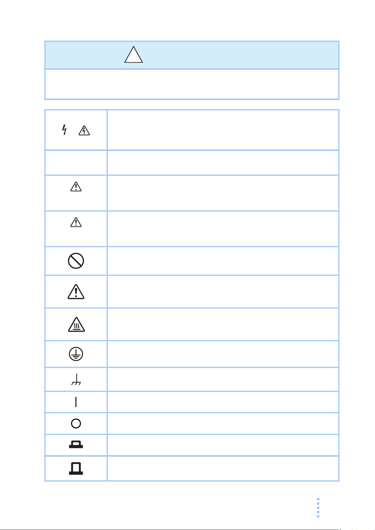
Indicates that a high voltage (over 1 000 V) is used here.
or
Touching the part causes a possibly fatal electric shock. If physical
contact is required by your work, start work only after you make sure that
no voltage is output here.
DANGER
WARNING
CAUTION
Indicates an imminently hazardous situation which, if ignored, will result
in death or serious injury.
Indicates a potentially hazardous situation which, if ignored, could result
in death or serious injury.
Indicates a potentially hazardous situation which, if ignored, may result in
damage to the product and other property.
Shows that the act indicated is prohibited.
Indicates a general danger, warning, or caution.
When this symbol is marked on the product, see the relevant sections in
this manual.
Indicates a caution for hot surface of the product.
When this symbol is marked on the product, see the relevant sections in
this manual.
Protective conductor terminal.
Chassis (frame) terminal.
On (supply)
Off (supply)
In position of a bi-stable push control
Out position of a bi-stable push control
PAT-T 4kW i
Safety Precautions
!
The following safety precautions must be observed to avoid fire hazards, electric
shock, accidents, and other failures. Keep them in mind and make sure to observe
them.
Using the product in a manner that is not specified in this manual may impair the
protection functions provided by the product.
Users
Operation
ual
an
M
Purpose of
use
Input power
Line
Voltage
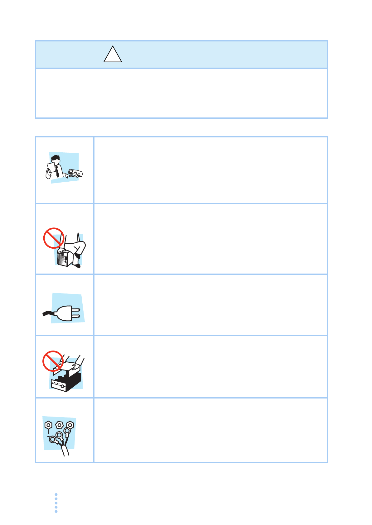
• This product must be used only by qualified personnel who
understand the contents of this operation manual and confirm safety of
the product.
•If unqualified personnel is to use the product, be sure the product is
handled under the supervision of qualified personnel (those who have
electrical knowledge). This is to prevent the possibility of personal
injury.
• Never use the product for purposes other than the product's intended
use.
• This product is not designed or manufactured for general home or
consumer use.
• Use the product within the rated input power voltage range.
• For applying power, use the power cable provided. For details, see the
respective page in the operation manual.
• This product is designed as an equipment of IEC Overvoltage
Category II (energy-consuming equipment supplied from the fixed
installation).
Cover
Grounding
N
G
ii PAT-T 4kW
L
• Some parts inside the product may cause physical hazards. Do not
remove the external cover.
• This product is an IEC Safety Class I equipment (equipment with a
protective conductor terminal). To prevent the possibility of electric
shock, be sure to connect the protective conductor terminal of the
product to electrical ground (safety ground).
Installation
• This product is designed for safe indoor use. Be sure to use it indoors.
• When installing this product, be sure to observe the description
referred to the applicable section in this operation manual.
Relocation
Operation
Check?
Maintenance
and
inspection
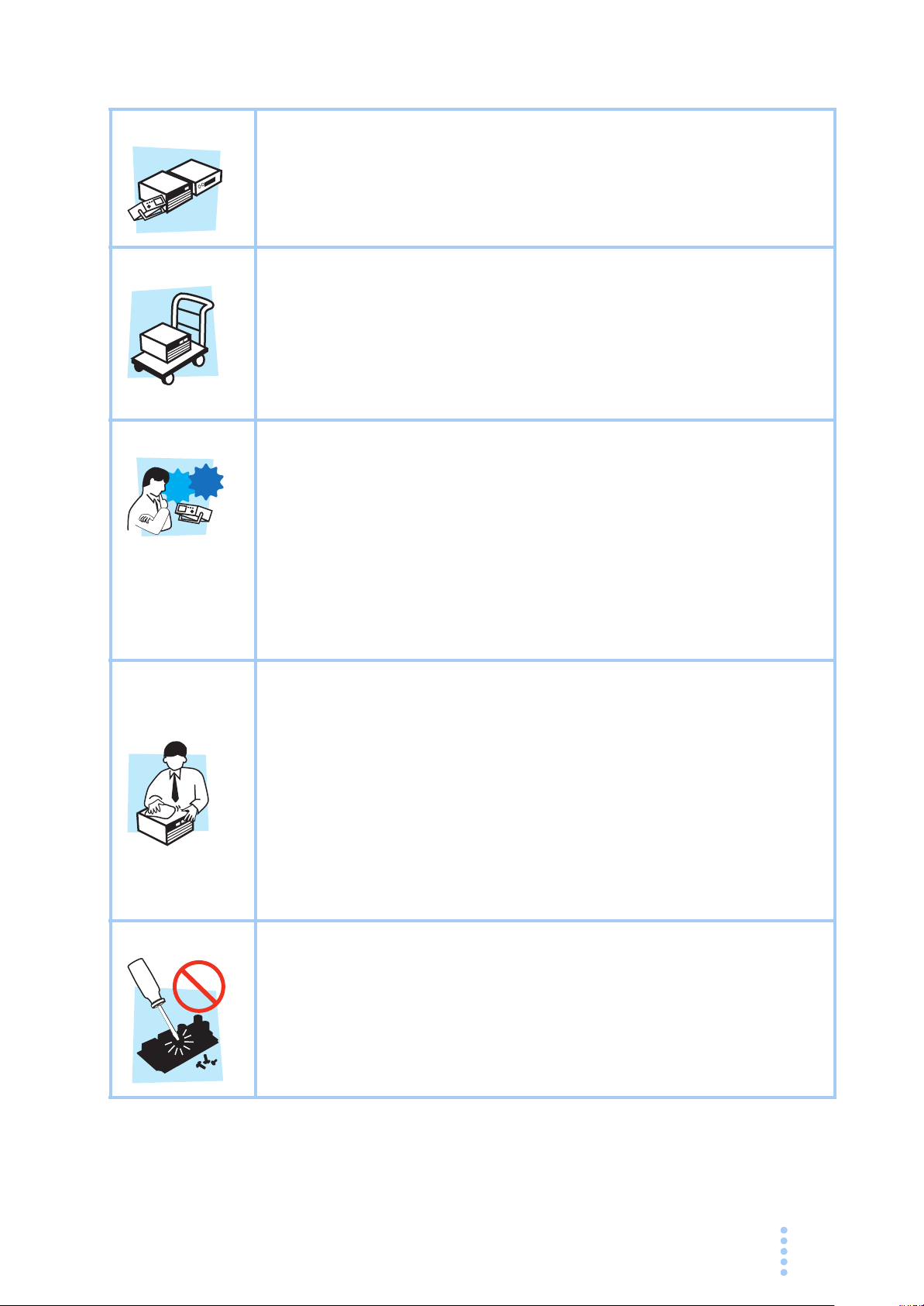
•Turn off the POWER switch, and disconnect all cables before
relocating the product.
• The product weighs over 20 kg. When moving the product, have more
than one person carry it. The weight of the product is indicated on the
rear panel of the product and/or in the specification table in this
manual.
• When relocating the product, be sure to include the manual.
• Before using the product, be sure to check the input power voltage
and that there is no abnormality in the appearance of the power cable.
Be sure to turn off the switchboard breaker before checking.
•If a malfunction or abnormality is detected on the product, stop using it
immediately, and remove the power plug from the outlet. Make sure
the product is not used until it is completely repaired.
• Use cables or wires with sufficiently large current capacity for output
wires and load cables.
• Do not disassemble or modify the product. If you need to modify the
product, contact your Kikusui distributor/agent.
• To prevent electric shock, be sure to turn off the switchboard breaker
before carrying out maintenance or inspection. Do not remove the
external cover.
• Conduct periodic inspection for checking the tears or breaks of the
power cable.
Service
• If the panel needs cleaning, gently wipe using a soft cloth with water-
diluted neutral detergent. Do not use volatile chemicals such as
benzene or thinner.
• To maintain the performance and safe operation of the product, it is
recommended that periodic maintenance, inspection, cleaning, and
calibration be performed.
•Kikusui service engineers will perform internal service on the product.
If the product needs adjustment or repairs, contact your Kikusui
distributor/agent.
PAT-T 4kW iii
Warning
label
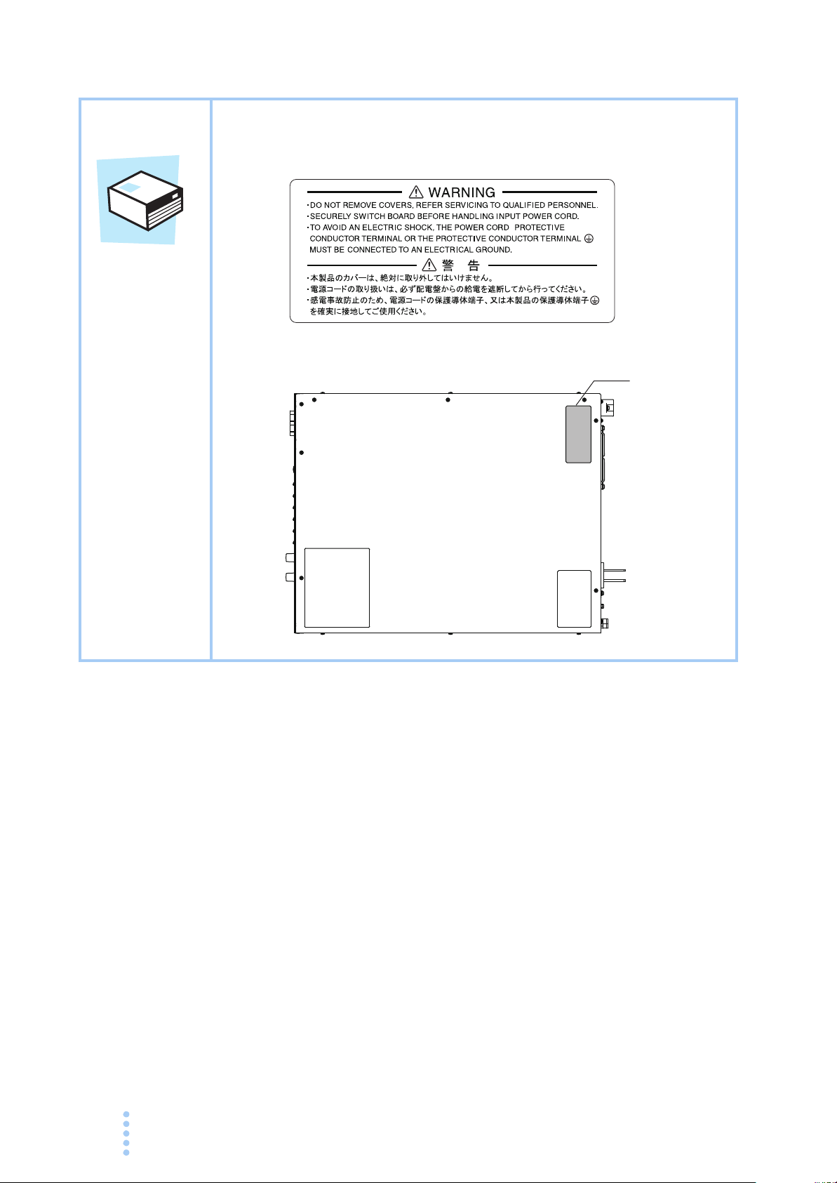
• There is a warning label affixed to the product. If this label tears or falls
off, replace with a new label. If you need a new label, contact your
Kikusui agent or distributor.
PAT- T
Top panel
Label
iv PAT-T 4kW

How to Read This Manual
Introduction
Thank you for purchasing the PAT-T Series regulated DC power supply.
This manual is intended for first-time users of the PAT. It gives an overview of the
PAT and describes various settings, operation, SCPI commands, maintenance, safety
precautions, etc.
Read this manual thoroughly to use the functions of the PAT effectively. You can
also review this manual when you are confused about an operation or when a
problem occurs.
How to read this manual
This manual is designed to be read from the beginning to the end. We recommend
that you read the manual thoroughly from the beginning before using the PAT for
the first time.
Intended readers of this manual
This manual is intended for those using the PAT or teaching your operators how to
use the PAT.
The manual assumes that the reader has knowledge about electrical aspects of power
supplies.
Information on SCPI commands is provided with the premise that the reader has
sufficient knowledge about controlling regulated DC power supplies using a
personal computer.
PAT-T 4kW v

Notations used in the manual
W ARNING
CAUTION
• In this manual, the PAT-T Series regulated DC power supply is often simply
referred to as “the PAT.”
• “PC” in this manual is a generic term for personal computers and workstations.
• The following marks are used with the explanations in this manual.
Indicates a potentially hazardous situation which, if ignored, could result in
death or serious injury.
Indicates a potentially hazardous situation which, if ignored, may result in
damage to the product and other property.
Indicates information that you should know.
Explanation of terminology or operation principle.
See
Indicates reference to detailed information.
SHIFT+key name (marked in blue)
Indicates an operation in which a key marked in blue is pressed while holding
down the SHIFT key.
CFxx : x
The first two characters “CF” indicates a configuration setting, and the next
two-digit number indicates the CONFIG parameter number. The character
after the colon indicates the selected setting.
vi PAT-T 4kW

Contents
Safety Symbols - - - - - - - - - - - - - - - - - - - - - - - - - - - - - - - - - - - - - - - - - - - - - - - - - i
Safety Precautions - - - - - - - - - - - - - - - - - - - - - - - - - - - - - - - - - - - - - - - - - - - - - - - ii
1
How to Read This Manual - - - - - - - - - - - - - - - - - - - - - - - - - - - - - - - - - - - - - - - - - v
Contents - - - - - - - - - - - - - - - - - - - - - - - - - - - - - - - - - - - - - - - - - - - - - - - - - - - - - vii
Contents by Function - - - - - - - - - - - - - - - - - - - - - - - - - - - - - - - - - - - - -xiii
Front panel - - - - - - - - - - - - - - - - - - - - - - - - - - - - - - - - - - - - - - - - - - - -xiv
Rear panel - - - - - - - - - - - - - - - - - - - - - - - - - - - - - - - - - - - - - - - - - - - - -xvi
Chapter 1 General Description
1.1 About This Manual - - - - - - - - - - - - - - - - - - - - - - - - - - - - - - - - - - - - - - - - - 1-2
1.2 Product Overview - - - - - - - - - - - - - - - - - - - - - - - - - - - - - - - - - - - - - - - - - 1-2
Features - - - - - - - - - - - - - - - - - - - - - - - - - - - - - - - - - - - - - - - - - - - - - 1-2
Options - - - - - - - - - - - - - - - - - - - - - - - - - - - - - - - - - - - - - - - - - - - - - - 1-4
Chapter 2 Installation and Preparation
2.1 Checking the Package Contents - - - - - - - - - - - - - - - - - - - - - - - - - - - - - - - 2-2
2.2 Precautions Concerning Installation- - - - - - - - - - - - - - - - - - - - - - - - - - - - - 2-3
2.3 Precautions to Be Taken When Moving the Product - - - - - - - - - - - - - - - - - 2-4
2.4 Rack Mounting the Product- - - - - - - - - - - - - - - - - - - - - - - - - - - - - - - - - - - 2-5
2.5 Connecting the Power Cable - - - - - - - - - - - - - - - - - - - - - - - - - - - - - - - - - 2-6
(Three-phase input Mode) Connection procedure - - - - - - - - - - - - - - - - 2-7
(Single-phase input Mode) Connection procedure - - - - - - - - - - - - - - - - 2-8
2
3
4
5
6
7
2.6 Turning On - - - - - - - - - - - - - - - - - - - - - - - - - - - - - - - - - - - - - - - - - - - - - - 2-9
Chapter 3 Connecting the Load
3.1 Load Considerations - - - - - - - - - - - - - - - - - - - - - - - - - - - - - - - - - - - - - - - 3-2
3.2 Load Cable - - - - - - - - - - - - - - - - - - - - - - - - - - - - - - - - - - - - - - - - - - - - - - 3-4
3.3 Connecting to the Output terminal - - - - - - - - - - - - - - - - - - - - - - - - - - - - - - 3-6
Chapter 4 Basic Operation
4.1 Phase input mode
(Single-phase input, Three-phase input) - - - - - - - - - - - - - - - - - - - - - - - - - 4-2
4.2 Measured Value Display and Setting Display
(Setting the Output Voltage and Output Current) - - - - - - - - - - - - - - - - - - - 4-3
4.3 Output Operation- - - - - - - - - - - - - - - - - - - - - - - - - - - - - - - - - - - - - - - - - - 4-4
4.4 Constant Voltage (CV) and Constant Current (CC) Power Supplies - - - - - - 4-6
4.5 Using the PAT as a CV or CC Power Supply
(Setting the Output Voltage and Output Current) - - - - - - - - - - - - - - - - - - - 4-8
4.6 Protection Functions and Alarms- - - - - - - - - - - - - - - - - - - - - - - - - - - - - - - 4-9
Alarm occurrence and release - - - - - - - - - - - - - - - - - - - - - - - - - - - - - - 4-9
4.6.1 Overvoltage protection (OVP) and overcurrent protection (OCP) - - 4-10
OVP and OCP trip point settings - - - - - - - - - - - - - - - - - - - - - - - - - - - 4-11
Checking the OVP or OCP operation - - - - - - - - - - - - - - - - - - - - - - - - 4-12
4.6.2 Other Protection Functions - - - - - - - - - - - - - - - - - - - - - - - - - - - - 4-13
4.7 CONFIG Settings- - - - - - - - - - - - - - - - - - - - - - - - - - - - - - - - - - - - - - - - - 4-15
8
9
Appx
PAT-T 4kW vii

Setup and view procedure of CONFIG parameters - - - - - - - - - - - - - - - 4-16
CONFIG parameter details - - - - - - - - - - - - - - - - - - - - - - - - - - - - - - - - 4-17
4.8 Preset Memory Function - - - - - - - - - - - - - - - - - - - - - - - - - - - - - - - - - - - - 4-24
Storing the preset memory values - - - - - - - - - - - - - - - - - - - - - - - - - - 4-24
Recalling the preset memory values - - - - - - - - - - - - - - - - - - - - - - - - - 4-25
4.9 Lock Function - - - - - - - - - - - - - - - - - - - - - - - - - - - - - - - - - - - - - - - - - - - 4-25
4.10 Switching from Remote to Local Mode - - - - - - - - - - - - - - - - - - - - - - - - - - 4-26
4.11 Remote Sensing Function - - - - - - - - - - - - - - - - - - - - - - - - - - - - - - - - - - - 4-26
Connection of the sensing cable - - - - - - - - - - - - - - - - - - - - - - - - - - - - 4-27
4.12 Factory Default Settings - - - - - - - - - - - - - - - - - - - - - - - - - - - - - - - - - - - - 4-29
Chapter 5 External Control
5.1 Overview of External Control - - - - - - - - - - - - - - - - - - - - - - - - - - - - - - - - - - 5-2
5.2 J1 Connector - - - - - - - - - - - - - - - - - - - - - - - - - - - - - - - - - - - - - - - - - - - - - 5-2
5.3 Output Terminal Insulation - - - - - - - - - - - - - - - - - - - - - - - - - - - - - - - - - - - 5-5
5.3.1 When the Output Terminal Is Not Grounded (Floating) - - - - - - - - - - 5-6
5.3.2 When the Output Terminal Is Grounded - - - - - - - - - - - - - - - - - - - - 5-7
5.4 Controlling the Output Voltage - - - - - - - - - - - - - - - - - - - - - - - - - - - - - - - - - 5-9
5.4.1 External Voltage (Vext) Control- - - - - - - - - - - - - - - - - - - - - - - - - - - 5-9
5.4.2 External Resistance (Rext) Control - - - - - - - - - - - - - - - - - - - - - - - 5-11
5.5 Controlling the Output Current - - - - - - - - - - - - - - - - - - - - - - - - - - - - - - - - 5-13
5.5.1 External Voltage (Vext) Control- - - - - - - - - - - - - - - - - - - - - - - - - - 5-13
5.5.2 External Resistance (Rext) Control - - - - - - - - - - - - - - - - - - - - - - - 5-15
5.6 Controlling the Output On/Off - - - - - - - - - - - - - - - - - - - - - - - - - - - - - - - - 5-17
5.7 Shutdown Control Using External Contact - - - - - - - - - - - - - - - - - - - - - - - 5-19
5.8 External Monitoring- - - - - - - - - - - - - - - - - - - - - - - - - - - - - - - - - - - - - - - - 5-21
External monitoring of the output voltage and output current - - - - - - - - 5-21
External monitoring of the operation mode - - - - - - - - - - - - - - - - - - - - - 5-22
Chapter 6 Parallel/Series Operation
6.1 Master-Slave Parallel Operation - - - - - - - - - - - - - - - - - - - - - - - - - - - - - - - 6-2
6.1.1 Functions during Master-Slave Parallel Operation - - - - - - - - - - - - - 6-2
6.1.2 Connection (Parallel Operation) - - - - - - - - - - - - - - - - - - - - - - - - - - 6-4
Connecting the signal wires (parallel operation) - - - - - - - - - - - - - - - - - - 6-4
Connecting the load (parallel operation) - - - - - - - - - - - - - - - - - - - - - - - 6-5
6.1.3 Master-Slave Parallel Operation Setup - - - - - - - - - - - - - - - - - - - - - 6-6
6.1.4 Starting the Master-Slave Parallel Operation - - - - - - - - - - - - - - - - - 6-7
6.2 Series Operation - - - - - - - - - - - - - - - - - - - - - - - - - - - - - - - - - - - - - - - - - - 6-8
6.2.1 Functions during Series Operation - - - - - - - - - - - - - - - - - - - - - - - - 6-8
6.2.2 Load Connection (Series Operation) - - - - - - - - - - - - - - - - - - - - - - 6-10
6.2.3 Series Operation Setup - - - - - - - - - - - - - - - - - - - - - - - - - - - - - - - 6-10
6.2.4 Starting the Series Operation - - - - - - - - - - - - - - - - - - - - - - - - - - - 6-11
Chapter 7 Remote Control
7.1 Remote Control Overview - - - - - - - - - - - - - - - - - - - - - - - - - - - - - - - - - - - - 7-2
7.2 Instrument Interface Standards - - - - - - - - - - - - - - - - - - - - - - - - - - - - - - - - 7-2
viii PAT-T 4kW

7.3 VISA Library - - - - - - - - - - - - - - - - - - - - - - - - - - - - - - - - - - - - - - - - - - - - - 7-3
7.4 Interface Setup - - - - - - - - - - - - - - - - - - - - - - - - - - - - - - - - - - - - - - - - - - - 7-4
7.4.1 RS232C Control (Standard Equipped) - - - - - - - - - - - - - - - - - - - - - 7-4
7.4.2 GPIB Interface (Option)- - - - - - - - - - - - - - - - - - - - - - - - - - - - - - - - 7-6
7.4.3 USB Interface (Option) - - - - - - - - - - - - - - - - - - - - - - - - - - - - - - - - 7-7
7.4.4 LAN Interface (Option) - - - - - - - - - - - - - - - - - - - - - - - - - - - - - - - - 7-8
7.5 Overview of Messages - - - - - - - - - - - - - - - - - - - - - - - - - - - - - - - - - - - - - 7-10
7.5.1 SCPI Command Syntax - - - - - - - - - - - - - - - - - - - - - - - - - - - - - - 7-11
7.5.2 Parameters - - - - - - - - - - - - - - - - - - - - - - - - - - - - - - - - - - - - - - - 7-13
7.6 Command Description in This Manual - - - - - - - - - - - - - - - - - - - - - - - - - - 7-15
1
2
3
7.7 IEEE488.2 Common Commands- - - - - - - - - - - - - - - - - - - - - - - - - - - - - - 7-16
7.8 Output Setting - - - - - - - - - - - - - - - - - - - - - - - - - - - - - - - - - - - - - - - - - - - 7-21
Output on / off - - - - - - - - - - - - - - - - - - - - - - - - - - - - - - - - - - - - - - - - 7-21
Voltage Settings - - - - - - - - - - - - - - - - - - - - - - - - - - - - - - - - - - - - - - - 7-22
Current Settings - - - - - - - - - - - - - - - - - - - - - - - - - - - - - - - - - - - - - - - 7-22
7.9 Measurement Operation Settings - - - - - - - - - - - - - - - - - - - - - - - - - - - - - 7-23
7.10 Protection Function Settings - - - - - - - - - - - - - - - - - - - - - - - - - - - - - - - - - 7-23
Overvoltage protection settings - - - - - - - - - - - - - - - - - - - - - - - - - - - - 7-23
Voltage limit setting - - - - - - - - - - - - - - - - - - - - - - - - - - - - - - - - - - - - 7-23
Overcurrent protection settings - - - - - - - - - - - - - - - - - - - - - - - - - - - - 7-24
Current setting limit - - - - - - - - - - - - - - - - - - - - - - - - - - - - - - - - - - - - - 7-25
Operation when a protection function is activated- - - - - - - - - - - - - - - - 7-26
7.11 Releasing the Alarm- - - - - - - - - - - - - - - - - - - - - - - - - - - - - - - - - - - - - - - 7-26
7.12 Other System Configuration - - - - - - - - - - - - - - - - - - - - - - - - - - - - - - - - - 7-27
Sets the phase input mode
(Three-phase input/Single-phase input mode) - - - - - - - - - - - - - 7-27
Controlling the output on/off using an external contact - - - - - - - - - - - - 7-27
Controlling the constant voltage/current- - - - - - - - - - - - - - - - - - - - - - - 7-28
Setting the breaker trip - - - - - - - - - - - - - - - - - - - - - - - - - - - - - - - - - - 7-29
Setting the master-slave parallel operation - - - - - - - - - - - - - - - - - - - - 7-29
Monitoring the power on/off status the the external (J1) connector - - - - 7-30
Queries the state of the sensing switch - - - - - - - - - - - - - - - - - - - - - - 7-30
Displays communication error by performing a debug trace - - - - - - - - 7-30
7.13 Preset Memory Function- - - - - - - - - - - - - - - - - - - - - - - - - - - - - - - - - - - - 7-31
4
5
6
7
8
9
Appx
7.14 Trigger Function - - - - - - - - - - - - - - - - - - - - - - - - - - - - - - - - - - - - - - - - - 7-32
7.14.1 Setting Changes (Sequence 1: TRANsient Settings) - - - - - - - - - - 7-32
7.14.2 Output On/Off Delay Function (Sequence 2: OUTPUT Settings) - - 7-35
7.14.3 Measurement (Sequence 3: ACQuire Settings) - - - - - - - - - - - - - - 7-37
Sequence operation auto continue mode - - - - - - - - - - - - - - - - - - - - - 7-38
Clearing the measurement data - - - - - - - - - - - - - - - - - - - - - - - - - - - - 7-39
Measurement operation - - - - - - - - - - - - - - - - - - - - - - - - - - - - - - - - - 7-39
7.14.4 Aborting the Operation - - - - - - - - - - - - - - - - - - - - - - - - - - - - - - - 7-40
7.15 System Settings- - - - - - - - - - - - - - - - - - - - - - - - - - - - - - - - - - - - - - - - - - 7-41
7.16 Status Register and Status Report Function - - - - - - - - - - - - - - - - - - - - - - 7-43
7.16.1 IEEE488.2 Register Model - - - - - - - - - - - - - - - - - - - - - - - - - - - - 7-45
Status byte register - - - - - - - - - - - - - - - - - - - - - - - - - - - - - - - - - - - - 7-45
PAT-T 4kW ix

Event status register - - - - - - - - - - - - - - - - - - - - - - - - - - - - - - - - - - - - 7-46
7.16.2 SCPI Register Model - - - - - - - - - - - - - - - - - - - - - - - - - - - - - - - - - 7-47
OPERation status register - - - - - - - - - - - - - - - - - - - - - - - - - - - - - - - - 7-47
QUEStionable status register - - - - - - - - - - - - - - - - - - - - - - - - - - - - - - 7-49
Preset status - - - - - - - - - - - - - - - - - - - - - - - - - - - - - - - - - - - - - - - - - 7-51
Chapter 8 Maintenance
8.1 Inspection - - - - - - - - - - - - - - - - - - - - - - - - - - - - - - - - - - - - - - - - - - - - - - - 8-2
8.2 Cleaning the Dust Filter- - - - - - - - - - - - - - - - - - - - - - - - - - - - - - - - - - - - - - 8-2
8.3 Calibration - - - - - - - - - - - - - - - - - - - - - - - - - - - - - - - - - - - - - - - - - - - - - - - 8-5
8.3.1 Calibration Overview - - - - - - - - - - - - - - - - - - - - - - - - - - - - - - - - - - 8-5
8.3.2 Calibration Procedure - - - - - - - - - - - - - - - - - - - - - - - - - - - - - - - - - 8-6
Chapter 9 Specifications
9.1 Specifications- - - - - - - - - - - - - - - - - - - - - - - - - - - - - - - - - - - - - - - - - - - - - 9-2
AC input - - - - - - - - - - - - - - - - - - - - - - - - - - - - - - - - - - - - - - - - - - - - - - 9-2
Output specifications - - - - - - - - - - - - - - - - - - - - - - - - - - - - - - - - - - - - - 9-3
Display function - - - - - - - - - - - - - - - - - - - - - - - - - - - - - - - - - - - - - - - - - 9-4
Protection functions - - - - - - - - - - - - - - - - - - - - - - - - - - - - - - - - - - - - - - 9-5
Output signals - - - - - - - - - - - - - - - - - - - - - - - - - - - - - - - - - - - - - - - - - - 9-6
Control functions - - - - - - - - - - - - - - - - - - - - - - - - - - - - - - - - - - - - - - - - 9-7
Interface - - - - - - - - - - - - - - - - - - - - - - - - - - - - - - - - - - - - - - - - - - - - - - 9-8
Other functions - - - - - - - - - - - - - - - - - - - - - - - - - - - - - - - - - - - - - - - - - 9-8
General specifications - - - - - - - - - - - - - - - - - - - - - - - - - - - - - - - - - - - - 9-9
9.2 Dimensions - - - - - - - - - - - - - - - - - - - - - - - - - - - - - - - - - - - - - - - - - - - - - 9-10
Appendix
A.1 Lists of Messages- - - - - - - - - - - - - - - - - - - - - - - - - - - - - - - - - - - - - - - - - - A-2
A.2 A List of Errors - - - - - - - - - - - - - - - - - - - - - - - - - - - - - - - - - - - - - - - - - - - -A-7
A.3 Default Conditions - - - - - - - - - - - - - - - - - - - - - - - - - - - - - - - - - - - - - - - - A-10
A.4 Processing time of Commands - - - - - - - - - - - - - - - - - - - - - - - - - - - - - - - A-11
A.5 Access and Operation for the Built-in Web site (LAN interface) - - - - - - - - - A-11
A.6 Tutorial - - - - - - - - - - - - - - - - - - - - - - - - - - - - - - - - - - - - - - - - - - - - - - - - A-16
A.6.1 Turning the Power On and Resetting the Instrument- - - - - - - - - - - A-16
A.6.2 Output Programming - - - - - - - - - - - - - - - - - - - - - - - - - - - - - - - - - A-17
A.6.3 Using Triggers - - - - - - - - - - - - - - - - - - - - - - - - - - - - - - - - - - - - - A-18
Setting changes (Sequence 1: TRANsient) - - - - - - - - - - - - - - - - - - - - A-19
Output on/off delay function (Sequence 2: OUTPut) - - - - - - - - - - - - - A-20
Measurement (Sequence 3: ACQuire) - - - - - - - - - - - - - - - - - - - - - - - A-21
Auto continue - - - - - - - - - - - - - - - - - - - - - - - - - - - - - - - - - - - - - - - - A-23
A.6.4 Status Monitoring - - - - - - - - - - - - - - - - - - - - - - - - - - - - - - - - - - - A-24
A.6.5 Error Checking - - - - - - - - - - - - - - - - - - - - - - - - - - - - - - - - - - - - - A-26
A.7 Sample Programs- - - - - - - - - - - - - - - - - - - - - - - - - - - - - - - - - - - - - - - - - A-27
A.8 Troubleshooting - - - - - - - - - - - - - - - - - - - - - - - - - - - - - - - - - - - - - - - - - - A-32
Index
x PAT-T 4kW
Contents by Function
See
Preparation
1
Situation Heading
How do I check the accessories. 2.1, “Checking the Package Contents” 2-2
The installation space is limited. How much space is needed
around the air inlet and outlet?
How do I connect the AC power supply? 2.5, “Connecting the Power Cable” 2-6
What kind of wires should be used to connect to the AC power
supply?
How can I use the PAT in the single-phase input ? “2.6 Turning On
How do I change the phase input mode?
(from the single-phase input to the three-phase input)
How do I change the phase input mode?
(from the three-phase input to the single-phase input)
What kind of wires should be used to connect the load? 3.2, “Load Cable” 3-4
The wire connecting the load is long (distance to the load is
long), but stable voltage is required.
How do I set the communication conditions for remote control? 7.4, “Interface Setup” 7-4
How do I control the output voltage using an external DC
voltage?
How do I increase the current capacity in parallel operation? 6.1, “Master-Slave Parallel Operation” 6-2
How do I rack mount the PAT? What kind of parts is needed? “ Options” 1-4
2.2, “Precautions Concerning Installation” 2-3
2.5, “Connecting the Power Cable” 2-6
“4.7 CONFIG Settings
“7.12 Other System Configuration
“4.7 CONFIG Settings
“7.12 Other System Configuration
“4.7 CONFIG Settings
“7.12 Other System Configuration
4.11, “Remote Sensing Function” 4-26
5.4.1, “External Voltage (Vext) Control” 5-9
Page
2-9
4-21
7-27
4-21
7-27
4-21
7-27
2
3
4
5
6
7
Operation
Situation Heading
How can I use the PAT as a constant voltage power supply
(CV)?
How can I use the PAT as a constant voltage current supply
(CC)?
I would like to operate the PAT at a given voltage. How do I
register the voltage in the preset memory?
When using the PAT in the single-phase input mode, is there
any difference in the setting range compared to the threephase input power?
How do I set the upper limit to prevent the voltage from being
increased too much?
How do I set the voltage in fine resolution? “ Fine adjustment function” 4-9
How do I set the protection function to prevent damage to the
load?
How do I cut off the output at a different time from other power
supplies?
How can I monitor the output voltage and output current? 5.8, “External Monitoring” 5-21
How do I temporarily lock the keys? 4.9, “Lock Function” 4-25
How do I use the sample program for remote control? A.7, “Sample Programs” A-27
How do I reset the PAT to factory default settings? 4.12, “Factory Default Settings” 4-29
4.5, “Using the PAT as a CV or CC Power
Supply (Setting the Output Voltage and Output
Current)”
4.8, “Preset Memory Function”
“4.5 Using the PAT as a CV or CC Power Supply
(Setting the Output Voltage and Output Current)
“4.6.1 Overvoltage protection (OVP) and
overcurrent protection (OCP)
“ Setting limit function”
4.6, “Protection Functions and Alarms”
4.6.1, “Overvoltage protection (OVP) and
overcurrent protection (OCP)”
“ Output on/off delay functions”
See
Page
4-8
4-24
4-8
4-10
4-11
4-9
4-10
4-5
8
9
Appx
PAT-T 4kW xi
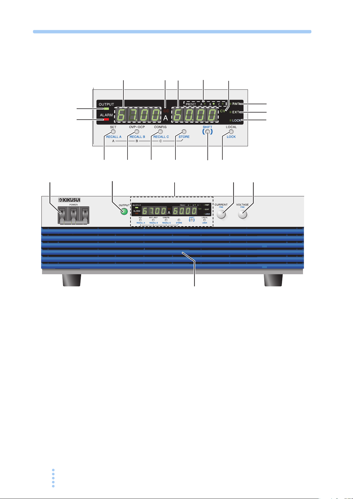
Front panel
V
PAT 60-67T
REGULATED DC POWER SUPPLY
0-60V 67A
1
2
Displayandkeys
3
4
5
11
12
OUTPUT
ALARM
16
6
REGULATED DC POWER SUPPLY
0-60V 67A
A V
17
18
8
7
9
10
PAT 60-67T
20
C
CV
V
RMTRMT
EXTEXT
LOCK
13
14
15
B
21
A
PRESET
CCCC
C
C
19
Examples of PAT60-67T
xii PAT-T 4kW

No. Name Function
See
POWER switch Power on/off lever
1
Raise the lever to turn the power on ( ). Lower to turn the power off (
).
+STORE To change the phase input mode to the single-phase input, press the
POWER switch with pressing the STORE key.
OUTPUTswitch Output on/off switch. 4-4
2
CURRENT knob Used to set the current value or select the CONFIG parameter number. –
3
+SHIFT FINE Current adjustment knob when the fine adjustment function is enabled. 4-9
VOLTAGE knob Used set the voltage value or change the CONFIG parameter setting. –
4
+SHIFT FINE Voltage adjustment knob when the fine adjustment function is enabled. 4-9
Air inlet (louver) Inlet for taking in air from the outside. A dust filter is built in. 8-2
5
Ammeter Displays the current value or the CONFIG parameter number. –
6
CC Illuminates in constant current mode. 4-8
7
Volt meter Displays the voltage value or the CONFIG parameter setting. –
8
PRESET The LED of the preset memory in use illuminates. 4-24
9
CV Illuminates during constant voltage mode. 4-8
10
OUTPUT LED Illuminates when output is on and turns off when output is off. 4-3
11
ALARM LED Illuminates when a protection circuit is activated. 4-9
12
RMT LED Illuminates when operating in remote control. 4-26
13
EXT LED Illuminates when operating in external analog remote control. 5-2
14
LOCK LED Illuminates when panel operations except turning the output on/off and
15
SET key Key with an LED for setting and checking the output voltage or output
16
+SHIFT RECALL A Key for recalling the value of preset memory A 4-25
+STORE A Key for saving the value to preset memory A. Press STORE and then A. 4-24
17
OVP•OCP key
+SHIFT RECALL B Key for recalling the value of preset memory B 4-25
+STORE B Key for saving the value to preset memory B. Press STORE and then B. 4-24
CONFIG key Key with an LED for setting various conditions concerning the
18
+SHIFT RECALL C Key for recalling the value of preset memory C 4-25
+STORE C Key for saving the value to preset memory C. Press STORE and then C. 4-24
STORE key Key for storing the preset memory 4-24
19
SHIFT key Key for calling up the functions marked in blue characters. vi
20
LOCAL key Key for changing between remote and local modes. 4-26
21
+SHIFT LOCK Key for disabling only the operations that change the settings (keeping
viewing settings.
current.
Key with an LED for setting and checking the trip points of the
overvoltage protection (OVP) and overcurrent protection (OCP).
operation.
the display and recall operations enabled).
*1
1
Page
2
2-9
3
4
5
6
7
4-25
8
4-8
9
4-10
Appx
4-15
4-25
*1. Once the single-phase input mode is set to turn on the power, the PAT will be turned on in the single-phase input
mode for next time.
PAT-T 4kW xiii
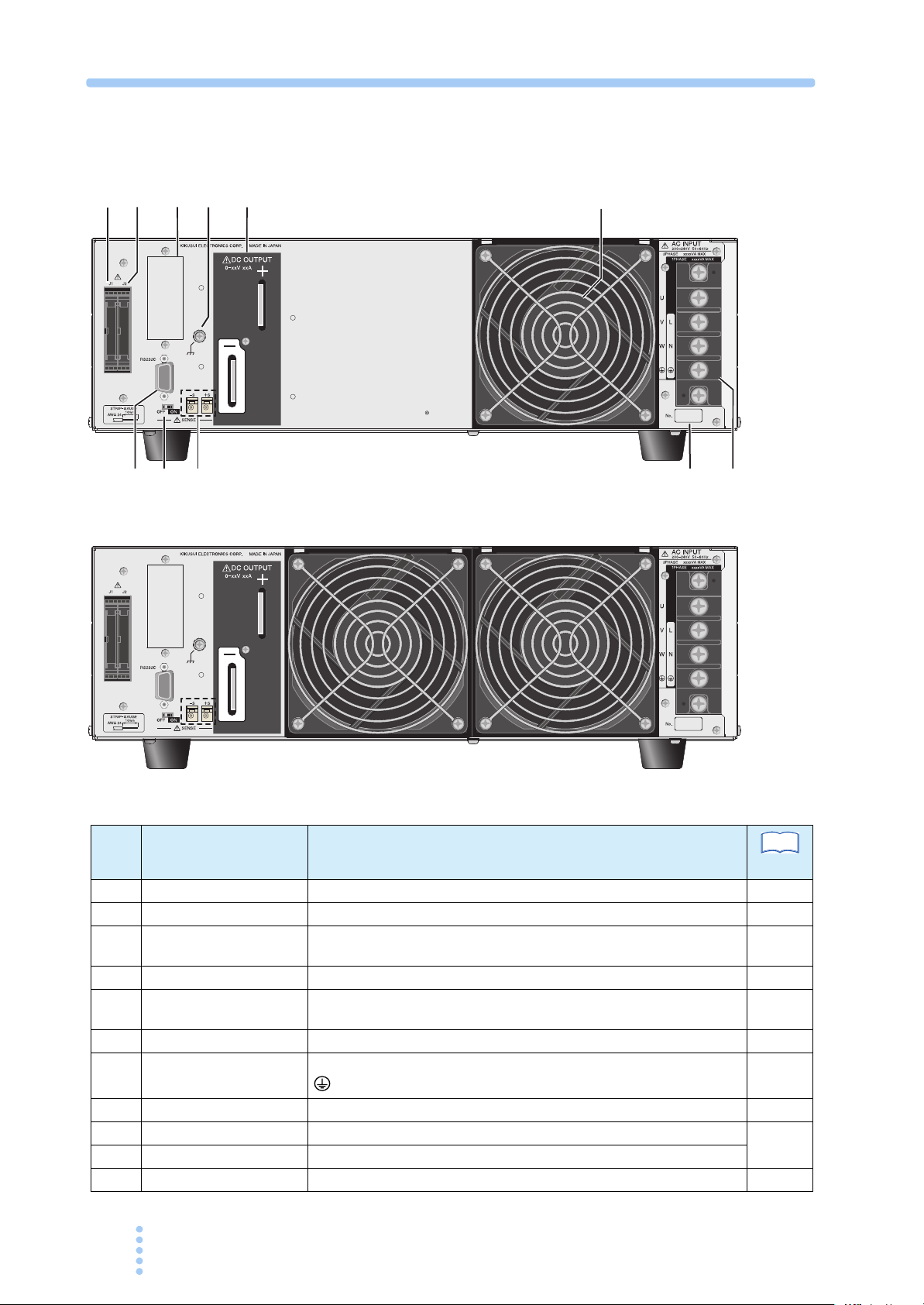
Rear panel
23
22
32
31
24
30
25
26
2#662#662#66
27
29
28
2#66
No. Name Function
J1 Connector for external analog control. 5-2
22
J2 Connector for parallel operation. 6-4
23
Option slot Slot for installing the optional interface board (GPIB, USB or LAN). A
24
Chassis terminal Te r mi n a l used to ground the output. 3-6
25
DC OUTPUT Output terminal. 3-4
26
Air outlet Exhaust port for cooling. 2-3
27
AC INPUT Input terminal. (Three-phase input/Single-phase input) Including the
28
Serial number The serial number of the PAT. –
29
Sensing terminal A terminal used to connect the sensing wires.
30
Sensing switch Switch for enabling/disabling remote sensing.
31
RS232C Connector for the RS232C cable. 7-4
32
factory option.
(GND) terminal.
See
Page
7-6
7-7
3-6
2-6
4-26
xiv PAT-T 4kW

General Description
This chapter describes an overview and describes the
features.

1.1 About This Manual
This manual describes the PAT-T Series (4 kW type), regulated DC power supply.
Applicable firmware version of the PAT
See
See
p. 2-9
p. 7-17
This manual applies to PATs with firmware version 4.0x.
When making an inquiry about the product, please provide us with the following
information.
• Model (indicated at the top section on the front panel)
• Firmware version
• Serial number (indicated at the bottom section on the rear panel)
This product information can also be obtained using the *IDN? remote control
command.
1.2 Product Overview
The PAT is a low-noise, highly efficient Constant Voltage (CV)/Constant Current
(CC) automatic crossover power supply that employs a software switching system.
The input power mode is selectable for the three-phase input mode (200 V system) or
single-phase input mode (200 V system).
Capable to expand the system up to a maximum output of 20 kW (in the three-phase
input
mode) or 15 kW (in the single-phase input mode) by the master-slave parallel
operation.
Features
The communication function (RS232C) for remote control also comes standard with
the product.
● Selectable input power for the three-phase input mode (200 V system) or
single-
Possible to operate in the single-phase input mode (200 V system). The input
power mode can be switched from “three“singlephase input mode, output current is limited to 75 % of the rating of three-phase
input
● Reduction of harmonic current and power transmission loss
The power-factor improvement circuit reduces the effects of harmonic currents
on the input power line. It also suppresses the peak current and reduces the
power transmission loss.
phase input mode (200 V system)
phase input to single-phase input” or
phase input to three-phase input” by the CONFIG setting. (In the single-
mode.)
1-2 PAT-T 4kW

● Power Factor Correction circuit is equipped
• Reducing the cost of operation
Because of the reactive power is reduced, the power can be used without wasting
of power.
• Downsized input distribution device
The input distribution device (breaker) can be downsized, because the built-in
power-factor correction circuit reduces the required input current.
• Reducing the transmission loss and harmonic current
1
The effect of harmonic current on the input power is reduced. And the
transmission loss can be reduced by limiting the peak current of the input power
line.
● Master-Slave parallel operation
Up to five power supplies can be connected in parallel to expand the output
power to 20 kW (in the three-
mode) by the master-slave parallel operation.
input
● Output limit function
You can set the upper limit of current and voltage that is applied when setting the
output.
This function is used to prevent setting inappropriate value by mistake.
● Remote interface
Equipped with RS232C as standard. You can select the GPIB, USB or LAN
interface as a factory option.
The remote interface complies with IEEE 488.2 std 1992 and SCPI Specification
1999.0.
● High efficiency and low noise
High power conversion efficiency has reduced the rise in the internal temperature
and has contributed to the product’s compact and light design.
phase input mode) or 15 kW (in the single-phase
General Description
● Preset memory function of settings
Up to three output setting presets (combination of current and voltage) can be
saved.
You can simply select a preset to set the output without having to set the voltage
and current every time you use the PAT.
● Output on/off delay function
You can set a delay until the output is actually turned on or off after turning the
OUTPUT switch on or off.
For example, this feature is useful if you want to turn the output on/off by setting
a time offset according to the load characteristics.
PAT-T 4kW 1-3
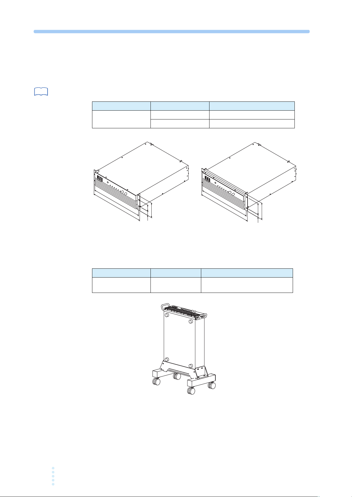
Options
18.83
(18.03)
2.24
1.48
5.20
KRB3-TOS
(458)
479.4
100
24.5
149
KRB150-TOS
Unit: mm
Unit: inch
The options listed below are available for the PAT-T Series.
For details on the options, contact your Kikusui agent or distributor.
See
p. 2-5
■ Rack mounting option
Product Model Note
Rack mount
bracket
KRB150-TOS Metric unit size rack JIS standard
■ Vertical stand
KRB3-TOS Inch unit size rack EIA standard
A vertical stand is used as a stand to hold the equipment in a vertical position.
Product Model Note
Vertical stand VS01
580 W x 245 H x 350 D mm (MAX)
(Excluding the size of the equipment)
1-4 PAT-T 4kW
p. 2-6
See
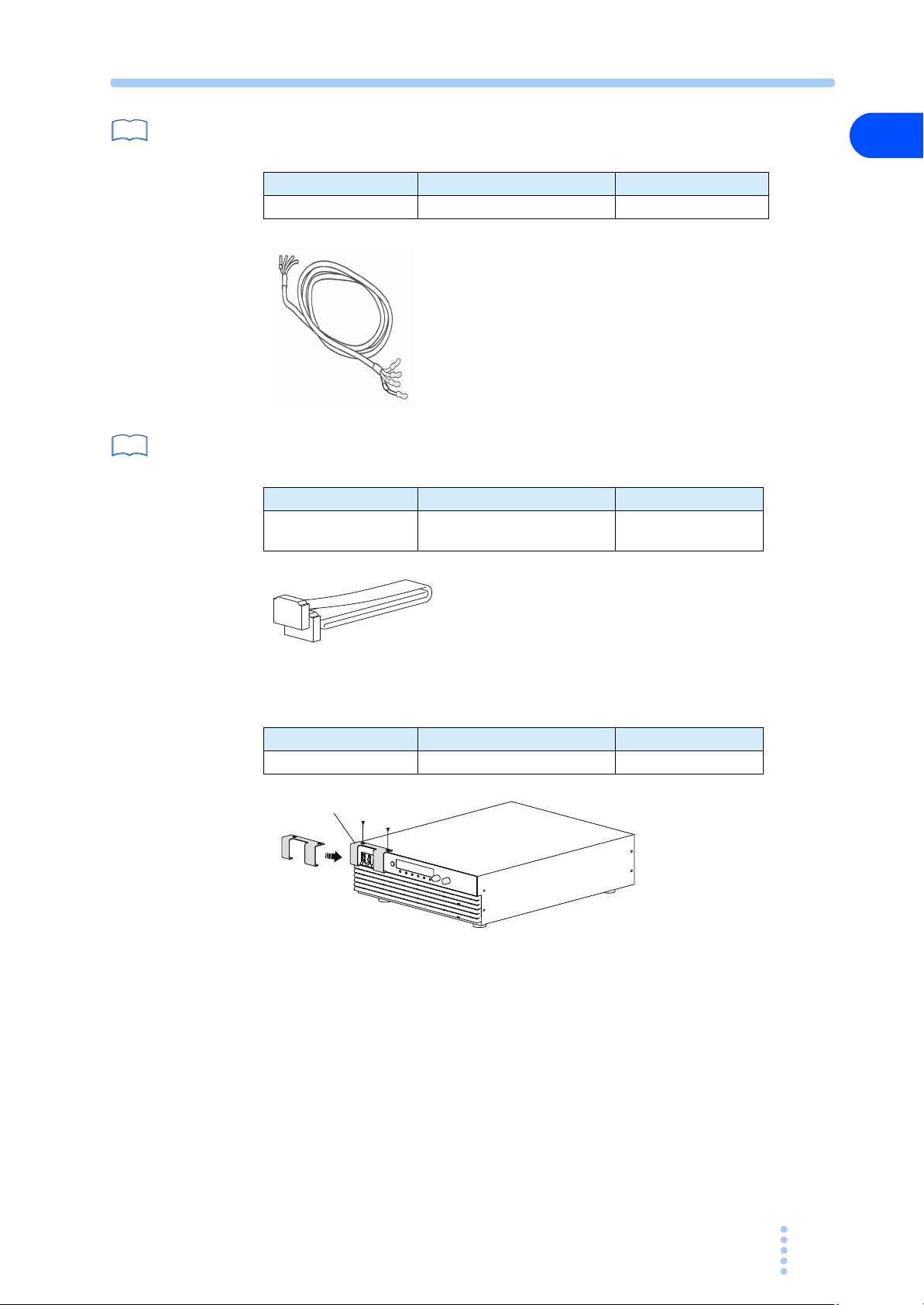
■ Power cable (for three-phase input)
A power cable to connect to the input terminal block on the rear panel.
Product Model Note
Power cable AC8-4P4M-M6C 4 m 4 cores
1
General Description
See
p. 6-4
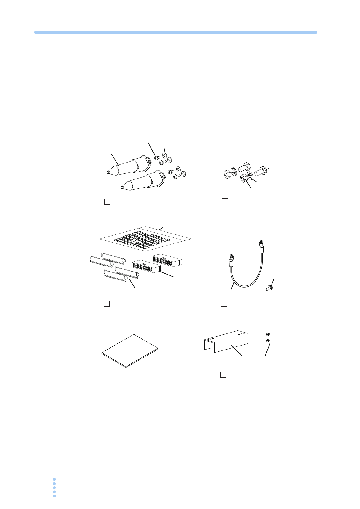
■ Cable for parallel operation
A cable used when performing parallel operation.
Product Model Note
Cable for parallel
operation
P C0 1- PAT 250 mm 26 pins
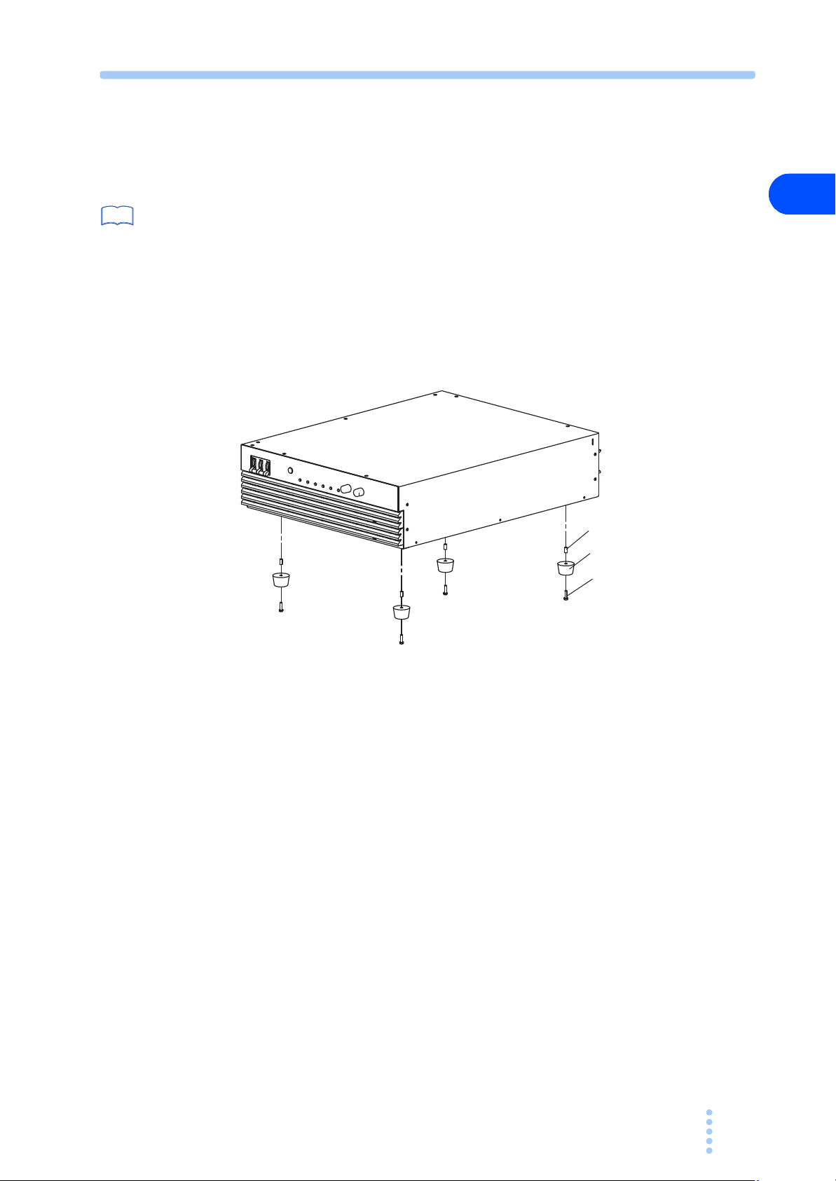
■ Power switch guard
A power switch guard is to prevent accidental operation of the POWER switch.
Product Model Note
Power switch guard O P0 1 - PAT –
Power switch guard
PAT-T 4kW 1-5

1-6 PAT-T 4kW

Installation and Preparation
This chapter describes the procedures of unpacking and
preparation of the PAT before use.
2.1 Checking the Package Contents
When you receive the product, check that all accessories are included and that the
accessories have not been damaged during transportation.
If any of the accessories are damaged or missing, contact your Kikusui agent or
distributor.
We recommend that all packing materials be saved, in case the product needs to be
transported at a later date.
OUTPUT terminal cover
[Q1-500-106]
OUTPUT terminal cover set (2 sets)
J1/J2 connector kit
[M3-111-010]
[M5-100-012]
Pins 30 pcs.
[84-49-0100]
Protection cover
2 sets
[84-49-0161]
Socket
2 pcs.
[84-49-0160]
[M1-100-019]
[M5-101-008]
[M4-100-008]
Output terminal bolt (M10) (2 sets)
[M3-112-027]
[91-80-6940]
Chassis connection wire set (1 set)
Operation manual (
[Z1-004-182]
1 pc
[Q1-500-094]
)
Terminal block cover (1 set)
[M3-112-012]
Fig.2-1 Accessories
2-2 PAT-T 4kW

2.2 Precautions Concerning Installation
Be sure to observe the following precautions when installing the product.
● Do not use the product in a flammable atmosphere.
To prevent the possibility of explosion or fire, do not use the product near
alcohol, thinner or other combustible materials, or in an atmosphere containing
such vapors.
● Avoid locations where the product is exposed to high temperature or
direct sunlight.
Do not install the product near a heater or in areas subject to drastic temperature
changes.
Operating temperature range: 0 °C to +50 ° C (+32 ° F to +122 ° F)
Storage temperature range: -25 ° C to +70 ° C (-13°F to +158 °F)
● Avoid humid environments.
Do not install the product in high-humidity locations–near a boiler, humidifier,
or water supply.
Operating humidity range: 20 %rh to 85 %rh (no condensation)
Storage humidity range: 90 %rh or less (no condensation)
Condensation may occur even within the operating relative humidity range. If
this happens, do not use the product until the condensation dries up completely.
● Be sure to use the product indoors.
This product is designed for safe indoor use.
2
Installation and Preparation
● Do not install the product in a corrosive atmosphere.
Do not install the product in a corrosive atmosphere or in environments
containing sulfuric acid mist, etc. This may cause corrosion of various
conductors and bad contacts of connectors leading to malfunction and failure, or
in the worst case, a fire.
However, operation in such environments may be possible through alteration. If
you want to use the PAT in such environments, consult your Kikusui agent or
distributor.
● Do not install the product in a dusty location.
Accumulation of dust can lead to electric shock or fire.
● Do not use the product where ventilation is poor.
The product employs a forced air cooling system. Air is taken in from the air
inlet on the front panel and exhausted from the air outlet on the rear panel.
Secure adequate space around the product to prevent the possibility of fire
caused by accumulation of heat.
Allow at least 20 cm of space between the air inlet/outlet and the wall (or
obstacles). Hot air (approximately 20
exhausted from the air outlet. Do not place objects that are affected by heat near
the air outlet.
● Do not place objects on the product.
° C higher than the ambient temperature) is
Placing heavy objects on top of the product may cause failures.
PAT-T 4kW 2-3

● Do not install the product on an inclined surface or location subj ect to
vibrations.
The product may fall or tip over causing damages and injuries.
● Do not use the product in a location where strong magnetic or electric
fields are nearby or a location where large amount of distortion and noise
is present on the input power supply waveform.
The product may malfunction.
● Do not use the product near highly sensitive measuring instrume nts or
transceivers.
The noise generated by the product may affect them.
2.3 Precautions to Be Taken When Moving the Product
Note the following points when moving the product or transporting the product to
the installation location.
● Lower the POWER switch lever to turn it off.
Moving the product while the POWER switch is turned on may cause electric
shock or damage.
● Remove all wiring.
Moving the product with the cables connected may cause wires to break or
injuries due to the product falling over.
● When transporting the product, be sure to use the original packing
materials.
Otherwise, damage may result from vibrations or from the product falling during
transportation.
● When moving the product, have more than one person carry it.
● Be sure to include this manual.
2-4 PAT-T 4kW
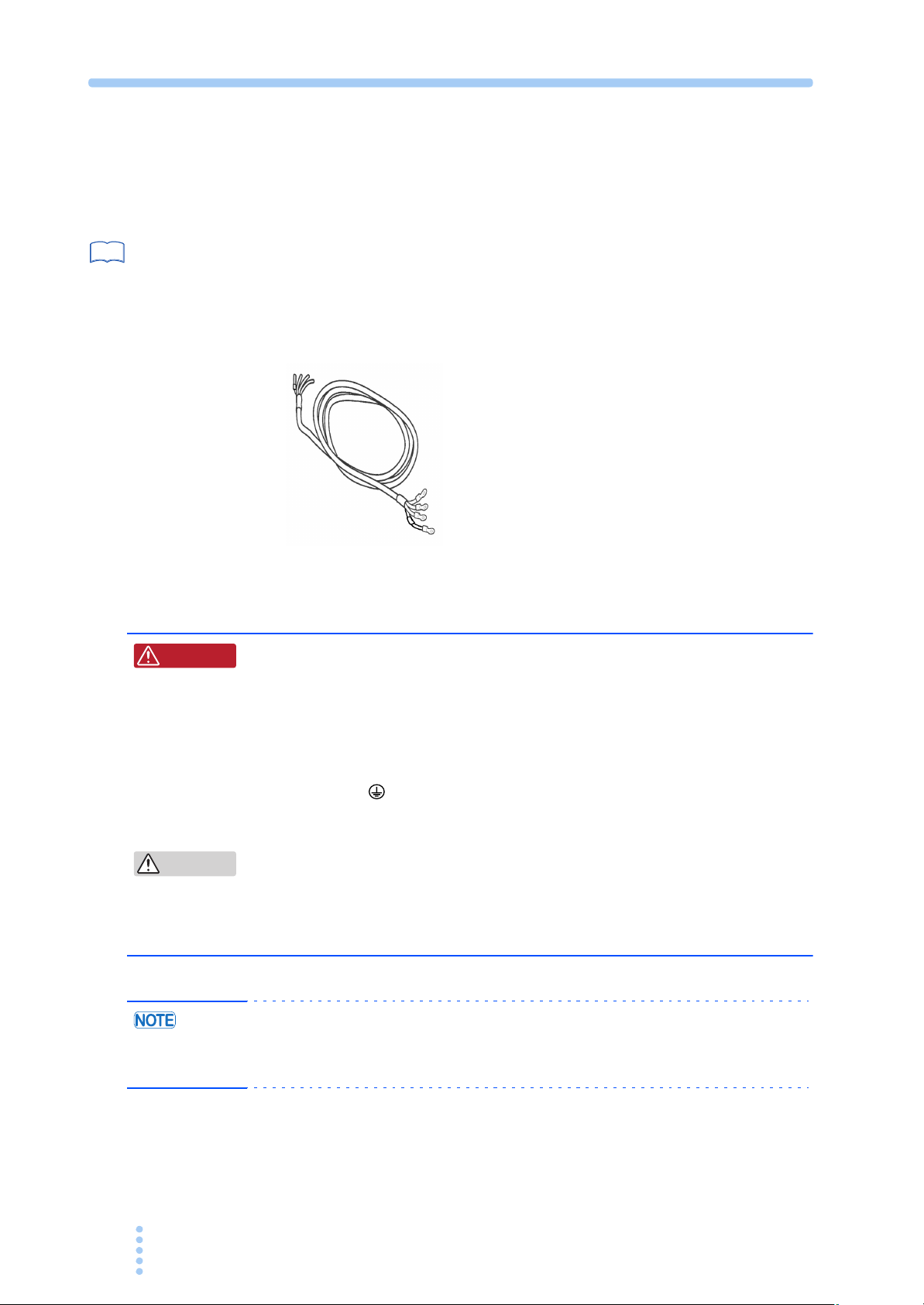
2.4 Rack Mounting the Product
Remove the rubber feet before rack mounting the product to a frame. Fig.2-2 shows
how to remove the rubber feet.
See
p. 1-4
For details on rack mounting, see the KRB3-TOS or KRB150-TOS Operation
Manual.
Install the suitable support angles applying to the used rack system to support the
instrument.
We recommend that you keep all the parts so that you can use them again when you
detach the product from the frame.
To reattach the rubber feet, use the screws that you removed.
2
Installation and Preparation
Collars (4 locations)
Rubber feet (4 locations)
Fig.2-2 Removing the rubber feet
Removing the rubber feet
Unfasten the screws and remove the four rubber feet.
Attachment screws
(4 locations)
M4 screw
( )
Maximum depth: 16 mm
PAT-T 4kW 2-5
2.5 Connecting the Power Cable
Three-phase input power cable
(AC8-4P4M-M6C)
This product is designed as an equipment of IEC Overvoltage Category II (energy-
consuming equipment supplied from the fixed installation).
See
p. 1-5
W ARNING
This product does not come with a power cable. In case the optional power cable
(AC8-4P4M-M6C) for three-phase input is used, attach crimping terminals that
comply with the terminal screws on the switchboard and connect the power cable
firmly so that it does not come loose. The crimping terminals connecting to the PAT
are already assembled.
Fig.2-3 Optional power cable
Exercise the following precautions when preparing the power cable.
Possible electric shock.
• Turn off the switchboard breaker (switch that cuts off the power
supply from the switchboard) before making the connection.
• This product is an IEC Safety Class I equipment (equipment with a
protective conductor terminal). Be sure to ground the product to
prevent electric shock.
• Connect the ground terminal to earth ground.
• Be sure to have a qualified engineer connect the power cable to the
switchboard.
CAUTION
2-6 PAT-T 4kW
• Inside the power supply, an appropriate protective circuit is connected to
the input terminal. Be sure to connect the wires correctly by following the
instruction for the connection of input phase mode either in singleinput mode or three-phase input mode.
• The POWER switch of the product can be used to disconnect the product from
the AC line in an emergency. Provide adequate space around the POWER switch
so that the POWER switch can be turned off at any time.
phase
W ARNING
GND
(GND)
W
V
U
(GND): Green
W: Black
U: Red
V: White
M6 screws
AC INPUT terminal block
Terminal block cover
Possible electric shock.
A maximum current of 17 A in the three-phase input mode and 22 A
in the single-phase input mode flows in the PAT at the rated load.
When switching the mode from the three-phase input mode to the
single-phase input mode, Be sure to use the appropriate type of
power cable as specified following instruction and refer to the
connection procedure for the single-phase input mode.
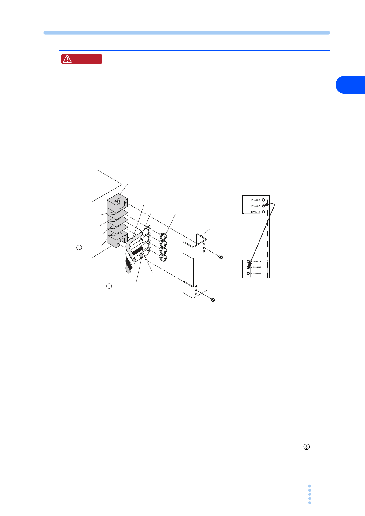
(Three-phase input Mode) Connection procedure
This product does not come with a power cable. Use a four-core PVC insulated
cable with a nominal cross-sectional area of at least 3.5 mm
2
for 600 Vac.
2
Use this screw hole
(for three-phase mode)
* When the power cable
layout is in reverse
direction, this terminal
cover should be attached in
the up-side down position.
Terminal block cover
( Three-phase mode)
Fig.2-4 Connecting the power cable for three-phase input mode
(example in which the optional power cable is used)
1
Check that the AC power line meets the nominal input rating of the
product.
The voltage that can be applied is any of the nominal power supply voltages in the
range of 200 Vac to 240 Vac. The frequency is 50 Hz or 60 Hz.
2
Check that the POWER switch is turned off.
Installation and Preparation
3
Connect the power cable to the AC INPUT terminal block as shown in
Fig.2-4
4
Attach crimping terminals to the switchboard end of the power cable.
Attach crimping terminals that comply with the terminal screws on the switchboard
5
Turn off the switchboard breaker.
6
Connect the power cable by matching the U, V, W, and (GND)
terminal of the switchboard.
Connect the power cable firmly so that it does not come loose.
PAT-T 4kW 2-7
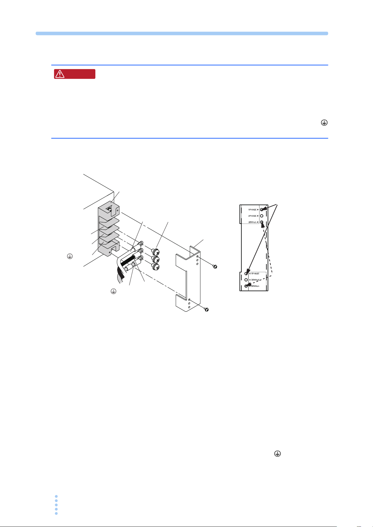
(Single-phase input Mode) Connection procedure
W ARNING
L
N
(GND)
Possible electric shock.
When connecting the input power in single-phase input mode, the
voltage around 100 V to 150 V are applied to the U terminal (the
terminal used for the three-phase input mode) on the input terminal
board. When in single-phase input mode, be sure to connect the
power cable to the L terminal and the N terminal, and connect the
ground terminal (GND terminal) to earth ground.
This product does not come with a power cable. Use a three-core PVC insulated
cable with a nominal cross-sectional area of at least 5.5 mm
AC INPUT terminal block
L
GND
(GND)
M6 screws
Terminal block cover
N
Terminal block cover
( Single-phase mode)
2
for 600 Vac.
Use this screw hole
(for single-phase mode)
* When the power cable
layout is in reverse
direction, this terminal
cover should be attached in
the up-side down position.
Fig.2-5 Connecting the power cable for single-phase input mode
1
Check that the AC power supply meets the nominal input rating of the
product.
The voltage that can be applied is any of the nominal power supply voltages in the
range of 200 Vac to 240 Vac. The frequency is 50 Hz or 60 Hz.
2
Check that the POWER switch is turned off.
3
Connect the power cable to the AC INPUT terminal block as shown in
Fig.2-5
4
Attach crimping terminals to the switchboard end of the power cable.
Attach crimping terminals that comply with the terminal screws on the switchboard
5
Turn off the switchboard breaker.
6
Connect the power cable by matching the L, N, and (GND) terminal
of the switchboard.
Connect the power cable firmly so that it does not come loose.
2-8 PAT-T 4kW

Precautions Concerning Grounding (Earth)
Be sure to ground the product for your safety.
Make sure to connect the GND terminal of the AC INPUT terminal block to the
GND terminal of the switchboard.
2.6 Turning On
Switching the phase input mode (Three phase input/Single
phase input)
2
See
p. 4-15
CAUTION
To confirm the status and the setting of phase input mode (three phase input or
single
phase input), please refer to the “4.7 CONFIG Settings”.
■ Three-phase input mode
The phase input mode is set for the three-phase input mode at the time of factory
shipment. Therefore, when the power is turned on, the threeactivated.
■ Single-phase input mode
When using the product in the single-phase input mode, press the POWER switch to
turn on while pressing the STORE key. Once the singleproduct will be started in the singlePOWER switch. If the input power connected to the singlepress the POWER switch without pressing the STORE key, the PAT will detect the
open-phase by the function of “Input open-phase protection (PHASE)”, and the
PAT will not be turned on.
The CONFIG parameters can be configured so that the output is
automatically turned on when the POWER switch is turned on. When this
function is enabled, the PAT powers up w ith the output turned on even if
the output was off when the PAT was turned off the last time. However,
there is a possibility that a load may break, if you connect a different load
and turn the POWER and output on simultaneously without changing the
OVP and OCP settings to appropriate values.
phase input mode next time just by pressing the
phase input mode is set, the
phase input mode is
phase input wiring, and
Installation and Preparation
Precautions Concerning Inrush Current
An inrush current (50 Amax.) flows when the POWER switch is turned on. In
particular, check that sufficient current capacity is available in the AC power line
and the switchboard if you are using multiple PATs and turning on the POWER
switches simultaneously.
PAT-T 4kW 2-9

Turning the POWER switch on
EXTEXT
RMT
LOCK
PRESET
A
B
C
A V
OUTPUT
ALARM
Indicates the version
Firmware version
See
See
p. 4-29
p. 4-3
If the POWER switch is turned on for the first time after purchasing the PAT, the
PAT starts up in a factory default condition.
1
Check that the power cable is correctly connected.
2
Raise the lever and turn the POWER switch on.
If an odd sound, odd odor, fire, or smoke occurs around or in the PAT, lower the
POWER lever to turn it off.
3
Check the firmware version on the front panel display.
The voltmeter and ammeter show the PAT firmware version for approximately 1
second. The measuring value will be shown after the firmware version is displayed.
Fig.2-6 Firmware version display at power-on (example for Ver.4.00)
■ If the error is displayed after turning the power on
If front panel display shows indicated in Table 2-1 after power-on, follow the
corresponding remedy. If the remedy does not correct the problem, contact your
Kikusui agent or distributor.
Table 2-1 Panel display during and after power-on
Panel Display Cause and Remedy
SYS1 ERR
SYS2 ERR
CLR ABC
CLR SET
CLR CONF
AV
AV
AV
AV
AV
The PAT may have malfunctioned. Contact your
Kikusui agent.
The calibration has not been completed normally.
Re-calibrate. If “SYS2 ERR” appears even after recalibration, the PAT may have malfunctioned. Contact
your Kikusui agent.
Preset memories A, B, and C have been reset to
factory default settings because the values were
abnormal. To continue the operation, press any panel
key.
The voltage and current calibration values have been
reset to factory default settings, because the values
were abnormal. To continue the operation, press any
panel key.
The CONFIG settings have been reset to factory
default values, because the values were abnormal.To
continue the operation, press any panel key.
2-10 PAT-T 4kW

CAUTION
Turning the POWER switch off
Lower the POWER switch lever to turn it off.
When the POWER switch is turned off, the front panel display shows the characters
indicated in the following figure for about 10 to 15 seconds.
2
C
A
OUTPUT
ALARM
PRESET
A V
B
Fig.2-7 Display at power-off
The PAT stores the panel settings (excluding output on/off condition) immediately
before the POWER switch is turned off. For these items, the PAT starts up using the
settings that existed when the POWER switch was turned off the last time.
If the POWER switch is turned off immediately after changing the settings, the last
settings may not be stored.
When turning the POWER switch off and then back on, allow at least 10
seconds after the fan stops. Repeated ON/OFF of the POWER switch at
short intervals can cause damage to the inrush current limiter or shorten
the service life of the POWER switch and the internal input fuse.
RMT
CV
EXTEXT
LOCK
Installation and Preparation
PAT-T 4kW 2-11

2-12 PAT-T 4kW

Connecting the Load
This chapter describes the consideration to be given to the
load, explains how to connect the load wires, and explains how
to connect to the
output terminals.

3.1 Load Considerations
Note that the output will become unstable if the following types of loads are
connected.
Load with peaks and pulse-shaped current
The PAT indicates only mean values. Even when the indicated value is less than the
preset current value, the peak values may actually exceed the preset current value. If
this happens, the PAT is instantaneously put into constant-current operation mode,
and the output voltage drops accordingly.
For these types of loads, you must increase the preset current value or increase the
current capacity.
Preset constant current value
Ammeter reading
(average value)
Preset constant c
Ammeter reading
(average value)
urrent value
Fig.3-1 Load current with peaks Fig.3-2 Pulse-shaped load current
Load that generates reverse current to the power supply
The PAT cannot absorb reverse current from the load. Therefore, if a regenerative
load (such as an inverter, converter, or transformer) is connected, the output voltage
increases and becomes unstable.
For these types of loads, connect a resistor RD as shown in Fig.3-3 to bypass the
reverse current. However, the amount of current to the load decreases by max.
reverse current I
EO
RD
rp.
−
IO
+
Load
Equivalent circuit of the PAT
+IO
0
Reverse current
O
-I
Output current waveform
Irp
RD[Ω] ≤
I
Regenerative load
[V]
E
O
[A]
rp
RD: Reverse current bypass dummy load
E
O: Output voltage
I
rp
: Max. reverse current
Fig.3-3 Remedy for regenerative load
CAUTION
• Use a resistor with sufficient rated power for resistor RD.
•If a resistor with insufficient rated power for the circuit is used, resistor RD
may burn out.
3-2 PAT-T 4kW

Load with accumulated energy
Connecting a load with accumulated energy, such as a battery, to the PAT may
cause current to flow from the load to the internal circuit of the PAT. This current
may damage the PAT or reduce the life of the battery.
For this type of loads, connect a reverse-current-prevention diode (DRP) between the
PAT and the load in series as shown in
Fig.3-4.
This cannot be used in conjunction with remote sensing.
RP
D
DRP: Reverse-current-prevention diode
3
CAUTION
PAT
Load with accumulated
energy
Fig.3-4 Remedy against load with accumulated energy
• Use a reverse-current-prevention diode (DRP) complied to the following
references.
Reverse voltage withstand capacity :
At least twice the rated output voltage of the PAT.
Forward current capacity :
Three to ten times the rated output current of the PAT.
A diode with small loss.
•Be sure to take into account the heat generated by reverse-current-
prevention diode D
RP. Reverse-current-prevention diode DRP may burn out
with inadequate heat dissipation.
Connecting the Load
PAT-T 4kW 3-3

3.2 Load Cable
W ARNING
To prevent the possibility of fire.
• Use a load cable with sufficient current capacity with respect to the
rated output current of the PAT.
• The output terminal and its area nearby gets very high temperature,
use the cable with sufficient heat resistance higher than
85 °C of the covering materials.
Possible electric shock.
• Use a load cable with a higher voltage rating than the isolation
voltage of the PAT. For the isolation voltage of each model, see
Chapter 9, “Specifications.”
■ Current capacity of the load cable
If their current rating exceeds the maximum rated output current, the cable will
remain intact even if the load becomes under the condition of short-circuited. Load
cables must be rated to carry the maximum rated output current of the PAT.
■ Allowable current of the cable dependent on the maximum allowable
temperature of the cable insulation
The cable temperature is determined by a current-caused resistance loss, ambient
temperature, and thermal resistance to the outside.
capacity of current that can flow through a heat-resistant PVC wire (single wire)
having a maximum allowable temperature of 60
horizontally in the air at an ambient temperature of 30
that PVC wires with lower heat-resistant temperature are used, the ambient
temperature exceeds 30
the current capacity needs to be reduced.
° C, or the wires are bundled resulting in low heat radiation,
Table 3-1 shows the allowable
° C when the wire is stretched
° C. If the condition is such
3-4 PAT-T 4kW

Table 3-1 Nominal cross-sectional area of cables and allowable
currents
Nominal cross-
sectional area [mm
2 14 (2.08) 27 10
3.5 12 (3.31) 37 -
5.5 10 (5.26) 49 20
8 8 (8.37) 61 30
14 5 (13.3) 88 50
22 3 (21.15) 115 80
30 2 (33.62) 139 -
38 1 (42.41) 162 100
50 1/0 (53.49) 190 -
60 2/0 (67.43) 217 -
80 3/0 (85.01) 257 200
100 4/0 (107.2) 298 -
125 - - 344 -
150 - - 395 300
200 - - 469 400
*1. Excerpts from Japanese laws related to electrical equipment.
AWG
2
]
(Reference cross-
sectional area) [mm
2
]
Allowable current
[A] (Ta = 30 ° C)
*1
Current
recommended by
Kikusui [A]
3
Connecting the Load
■ Taking measures against noise
When connecting wires that have the same heat-resistant temperature, more current
can flow by separating the wires to make heat radiation as great as possible.
However, installing the + (pos.) and - (neg.) output wires of the load cable side by
side or bundling them together is more effective against unwanted noise. The
Kikusui-recommended currents shown in
Table 3-1 are allowable current values
that have been reduced in consideration of the potential bundling of load cables. Use
these values as a guideline when connecting load cables.
■ Limitations of the sensing function
All wires have resistance. The voltage drop in wires becomes greater as the wire
becomes longer or the current becomes larger. This results in the voltage applied at
the load end to be smaller. The PAT has a sensing function that compensates for this
voltage drop up to approximately 0.6 V for a single line. If the voltage drop exceeds
this level, wires having a greater sectional area should be used.
PAT-T 4kW 3-5

3.3 Connecting to the Output terminal
See
W ARNING
p. 4-27
Possible electric shock.
• Be sure to turn the POWER switch off before touching the output
terminal.
• Be sure to attach the OUTPUT terminal cover after wiring the load.
Connection procedure
After the installation of the OUTPUT terminal cover for the output terminal, the
portion of the terminal cover is on top of the sensing terminal. In case the remote
sensing is used, install the
cable.
OUTPUT terminal cover after wiring of the sensing
OUTPUT terminal cover
The portion of sensing terminal is
covered by its plastic terminal cover.
Fig.3-5 Attachment completion of the OUTPUT terminal cover
■ How to use the OUTPUT terminal cover for the output terminal
Cut the sleeve of the OUTPUT terminal cover for the appropriate size of the load
cable which goes through its
OUTPUT terminal cover.
Ø10
Ø20
Ø30
Ø36
Ø10
Ø20 Line
Ø30 Line
Ø36 Line
Cut the OUTPUT terminal
co
ver of the load cable.
Fig.3-6 OUTPUT terminal cover
3-6 PAT-T 4kW

Connection preparation
Chassis connection wire
Screw
1
Turn the POWER switch off.
2
Using the chassis connection wire set that comes with the package,
connect the chassis terminal to either the negative or positive DC
output terminal.
The output terminal has a hole used to connect the chassis connection cable that comes
with the package.
3
Connecting the Load
Fig.3-7 Connecting the chassis connection wire
3
Attach crimping terminals to the load cable.
The output terminal has a hole for connecting the load cable. Attach the c r i m p i n g
terminal
4
Insert the load cable through the OUTPUT terminal cover.
5
Connect the load cable on the rear panel.
Insert the bolt for the positive (+) terminal from right side, and the negative (-) terminal
from left side as you face, then fix it using the nut and spring washers. Connect the
load cable straight forward (vertical angle against the surface of the
that matches the bolt used.
Crimp terminal
Spring washer
Nut
output terminal).
OUTPUT terminal cover
Bolt
Fig.3-8 Connection of the load cable
PAT-T 4kW 3-7

6
Install the OUTPUT terminal cover on the rear panel.
Uses the attached screws to install the OUTPUT terminal cover firmly and make sure
they are not loosen.
Screw
Washer
OUTPUT terminal cover
Fig.3-9 Attachment of the OUTPUT terminal cover
3-8 PAT-T 4kW

Basic Operation
This chapter describes how to turn on/off the output and the
basic operations that you can carry out from the front panel.

4.1 Phase input mode
CAUTION
(Single-phase input, Three-phase input)
The input power mode of the PAT (4 kW type) can be switched to either three-phase
input
or the single-phase input.
See
p. 4-15
See
p. 9-2
Descriptions Three-phase input mode Single-phase input mode
Output power 4 kW 3 kW
Output current setting range
Overcurrent protection
(OCP) setting range
Input open-phase protection
(PHASE)
(Monitor signal output)
(IMON) (Current)
at rated current output
(External control)
EXT-V CC CONT
(CC external voltage control)
EXT-R CC CONT
(CC external resistance
control normal)
EXT-R CC CONT
(CC external resistance
control fail safe)
Before starting the operation, confirm the status of phase input mode. To verify the
status and setting of the
phase input mode, refer to the “4.7 CONFIG Settings”.
The principal of difference in specifications for the phase input mode are described
as follows.
The detailed product specifications can be referred in the “9.1 Specifications”.
Tab le 4- 1 Major difference of the phase input mode
0 % to 105 % of rtg
10 % to 111.5 % of the rated output
current
Turns the output off. ALARM LED
illuminates.
10.00 V 0.25 V
0 % to 100 % of the rated output
current
in the range of 0 V to 10 V
0 % to 100 % of the rated output
current
in the range of 0 kΩ to 10 kΩ
100 % to 0 % of the rated output
current
in the range of 0 kΩ to 10 kΩ
*1
.
0 % to 105 % of rtg x 75 %
(10 % to 111.5 % x 75 %) of the rated
output current
Cancels the Input open-phase
protection feature.
7.50 V 0.25 V
The upper limit is set at 75 % of the
rating of the three-
0 % to 75% of the rated output current
(of the three-
range of 0 V to 7.5 V
0 % to 75 % of the rated output
current (of the three-
mode) in the range of 0 kΩ to 7.5 kΩ
75 % to 0 % of the rated output
current (of the three-
mode) in the range of 0 kΩ to 7.5 kΩ
phase input mode
phase input mode) in the
phase input
phase input
*1
.
4-2 PAT-T 4kW
*1. rtg : Indicates the rated output
• If the input power connected to the single-phase input wiring while the
PAT is set to the three-phase input mode, the function of “Input open-
phase protection (PHASE)” will be activated and the ALARM LED lights
on. On the other hand, If the input power connected to the threeinput
wiring while the PAT is set to the single-phase input mode, the
output current will be limited to 75 % of the rating of threemode. Confirm the status of phase input mode and the input wirings
properly.
phase
phase input

4.2 Measured Value Display and Setting Display (Setting the Output Voltage and Output Current)
The panel display has two modes. One mode displays the measured values of the
output voltage and output current, and the other mode displays the settings. These
two modes can be distinguished by the on/off state of the SET, OVP
CONFIG
keys.
•OCP, and
See
p. 4-8
• When the phase input mode is changed to the single-phase input mode from the
4
three-phase input mode, the setting value of the output current and the
overcurrent protection (OCP) is limited to 75 % of the rated value of output
current and the overcurrent protection of the three-phase input mode.
■ Measured value display
The measured value display shows the present output terminal voltage and load
current. In this mode, the LEDs of the SET, OVP•OCP, and CONFIG
keys are all
off.
You can change the output voltage and current settings in the measured value
display mode.
OUTPUT
ALARM
A
PRESET
B
A V
Switch turned off
RMT
CV
EXTEXT
LOCK
C
Fig.4-1 Measured value display example
■ Setting display
Basic Operation
The following three states are available.
• Setting display of the output voltage and output current
Press the SET key. The key LED illuminates. The present output voltage and
current are displayed.
OUTPUT
ALARM
Lights on
A
PRESET
B
A V
RMT
EXTEXT
LOCK
C
Fig.4-2 Setting display example of the output voltage and output
current
See
p. 4-24
PAT-T 4kW 4-3
If you save or recall a preset memory, the panel display shows the preset memory
values.

• Setting display of the overvoltage and overcurrent protection
Press the OVP•OCP key. The key illuminates. The present overvoltage and
overcurrent settings are displayed.
OUTPUT
ALARM
A
PRESET
B
A V
RMT
EXTEXT
LOCK
C
Lightson
Fig.4-3 Setting display example of the overvoltage and
overcu rrent protection
• Setting display of the system configuration
Press the CONFIG key. The key LED illuminates.The system configuration
settings are displayed.
C
OUTPUT
ALARM
A
PRESET
B
A V
RMT
EXTEXT
LOCK
On
Fig.4-4 Setting display example of the system configuration
4.3 Output Operation
The OUTPUT switch is a toggle switch.
When you press the OUTPUT switch and the output turns on, the OUTPUT LED
illuminates. When you press the OUTPUT switch and the output turns off, the
OUTPUT LED turns off.
If the output is turned on, the present setting is output. If you change the setting
while the output is on, the change is applied to the output.
See
p. 5-17
It is possible to control on/off of the output by external control.
Lights on
OUTPUT
ALARM
A V
Fig.4-5 Output on display example
Output on/off when power is turned on
PRESET
C
A
B
RMT
CV
EXTEXT
LOCK
By factory default, the output is off when the power is turned on. You can set the
output state at power-on to on (CF25: ON) in the CONFIG settings.
If you set the output state at power-on to on, check the OVP trip point setting before
you turn off the POWER switch.
If the breaker trip setting that is applied when an OVP or OCP activates is set to
“trip” (CF28: ON) and the OVP trip point is set lower than the output voltage
setting, the OVP will activate every time you turn the POWER switch on and the
POWER switch will turn off.
4-4 PAT-T 4kW

p. 4-29
See
If the condition above occurs and you are unable to change any of the settings, turn
the POWER switch on while holding down the SHIFT
key to reset the PAT to
factory default settings.
See
p. 4-17
p. A-20
CAUTION
• If the OVP/OCP settings are not appropriate when you change the load,
the load may break.
Output on/off delay functions
You can set a delay (0.1 s to 10.0 s) until the output is actually turned on or off after
you turn the OUTPUT switch on or off. This function is useful if you want to turn
the output on/off by setting a time offset according to the load characteristics.
To enable this function, set the output on delay (CF10: 0.1 to 10.0) and output off
delay (CF11: 0.1 to 10.0) of the CONFIG parameter. You can set separate delays for
on and off.
The OUTPUT LED blinks while the output on/off delay function is in operation.
Press the OUTPUT switch while the OUTPUT LED is blinking to cancel the output
on/off delay.
Press the OUTPUT switch while holding down the SHIFT key while the OUTPUT
LED is blinking to cancel the output on/off delay and forcibly switch the output.
Output on Output off
OUTPUT
LED
Off OffBlinking On Blinking
Output on
4
Basic Operation
Output off Output off
Output on
Cancel delay
Blinking Blinking
Delay Delay
Cancel output on delay
Output on by force
Blinking Blinking
Output on
Delay Delay
OUTPUT
LED
OUTPUT
LED
Output on
Off
Output off
Output on
Off Off
Output off Output off
Fig.4-6 Output on/off delay action
Output on
Blinking
Delay
On
Output off
Output off
Output on
Cancel output off delay
Output off by force
DelayDelay
Output off
Cancel delay
OnOn
PAT-T 4kW 4-5

4.4 Constant Voltage (CV) and Constant Current
A
B
A
B
(CC) Power Supplies
The PAT has a constant voltage power supply function that maintains the output
voltage at a constant level and a constant current power supply function that
maintains the output current at a constant level even when the load changes. The
condition in which the PAT is operating as a constant voltage power supply is called
the constant voltage (CV) mode. The condition in which the PAT is operating as a
constant current power supply is called the constant current (CC) mode. The
operation mode is determined by the following three values.
• Preset output voltage (Vs)
• Preset output current (Is)
• Load resistance (RL)
The operation modes are described below.
L>Rc
Vmax
Vs
Output voltage Vout
A
0
Output current Iout
R
p
B
L=Rc
R
Crossover point
RL <Rc
q
Imax Is
A = CV mode area
B = CC mode area
Vs = Preset voltage
Is = Preset current
Rc = Vs/Is (Ohm’s Law)
R
L = Load resistance
Vmax = Maximum preset voltage
Imax = Maximum preset current
Fig.4-7 Constant voltage operation and constant current
operation
Fig.4-7 shows the operation modes of the PAT. We denote the load resistance as RL
and the resistance calculated from the preset current and voltage as Rc (Rc = Vs/Is).
The power supply is designed so that it operates in CV mode in area
and CC
mode in area . The boundary is the line defined by RL = Rc. This line represents
the load at which the output voltage and the preset voltage are equal and the output
current and preset current are equal. If load resistance R
Rc, the operating point is in area
, and the PAT operates in CV mode (point p). In
L is greater than resistance
this case, preset current Is is the current limit.
When operating in CV mode, the output voltage is maintained at the preset voltage.
Output current I is determined by the relationship defined by the equation I = Vs/R
L.
It is a current less than current limit Is. In this mode, the actual current that flows is
not necessarily equal to the specified value.
For loads in which transient peak current flows, preset current Is must be set so that
the peak value does not reach the current limit.
Conversely, if load resistance RL is less than resistance Rc, the operating point is in
area
, and the PAT operates in CC mode (point q). In this case, preset voltage Vs
is the voltage limit.
4-6 PAT-T 4kW

When operating in CC mode, the output current is maintained at the preset current.
Output voltage V is determined by the relationship defined by the equation V = Is
RL. It is a voltage less than voltage limit Vs. In this mode, the actual voltage that is
applied is not necessarily equal to the specified value.
For loads that generate transient surge voltage, preset voltage Vs must be set so that
the surge voltage does not reach the voltage limit.
■ Crossover point
CV mode and CC mode switch automatically according to the changes in the load.
The point at which the mode switches is called the crossover point.
For example, if the load changes and the output current reaches the current limit
when operating in CV mode, the operation mode automatically switches to CC to
protect the load. Likewise, if the output voltage reaches the voltage limit when
operating in CC mode, the operation mode automatically switches to CV.
×
4
CV and CC mode operation example
This section uses a power supply with a rated output voltage of 100 V and a rated
output current of 10 A as an example.
A load resistance (RL) of 8 Ω is connected to the output terminals of the power
supply. The output voltage and output current are set to 30 V and 5 A, respectively.
In this case, Rc = 30 V/5 A = 6
operation mode is CV. If you want to increase the voltage in CV mode, the voltage
can be increased up to the voltage defined by the following equation: Vs = Is
Substituting the values, we obtain Vs = 5A
voltage above this point, the crossover point is reached, and the operation mode
automatically switches to CC mode. To maintain CV mode, increase the current
limit.
Next a load resistance (RL) of 5 Ω is connected to the output terminals of the power
supply. The output voltage and output current are set to 30 V and 5 A, respectively.
In this case, Rc = 30 V/5 A = 6
operation mode is CC. If you want to increase the current in CC mode, the current
can be increased up to the current defined by the following equation: Is = Vs/R
Substituting the values, we obtain Is = 30 V/5
current above this point, the crossover point is reached, and the operation mode
automatically switches to CV mode. To maintain CC mode, increase the voltage
limit.
Ω. Since, 8 Ω is greater than 6 Ω (RL > Rc), the
× RL.
× 8 Ω = 40 V. If you try to increase the
Ω. Since, 5 Ω is less than 6 Ω (RL < Rc), the
L.
Ω = 6 A. If you try to increase the
Basic Operation
PAT-T 4kW 4-7

4.5 Using the PAT as a CV or CC Power Supply (Setting the Output Voltage and Output Current)
When using the PAT as a constant voltage power supply, the preset current is the
limit that can flow through the load.
When using the PAT as a constant current power supply, the preset voltage is the
limit that can be applied to the load.
If the specified limit is reached, the operation mode automatically switches. If the
operation mode switches, it is indicated by changing the LED of CV or CC.
• When the phase input mode is changed to the single-phase input mode from the
three-phase input mode, the setting value of the output current and the
overcurrent protection (OCP) is limited to 75 % of the rated value of output
current and the overcurrent protection of the three-phase input mode.
1
Turn the POWER switch off.
2
Connect the load to the output terminal.
3
Turn the POWER switch on.
If the OUTPUT LED on the display is illuminated, press the OUTPUT switch to turn
the output off.
4
Check that the SET key is illuminated.
If it is not, press the SET key so that you can set the voltage and current.
5
Turn the VOLTAGE knob to set the voltage.
6
Turn the CURRENT knob to set the current.
7
Press the OUTPUT switch.
The OUTPUT LED on the display illuminates, and the voltage and current are
delivered to the
The CV LED illuminates when the PAT is operating as a constant voltage power
supply.
The CC LED illuminates when the PAT is operating as a constant current power
supply.
You can set the voltage and current by carrying out step 5 and step 6 while
checking the actual output voltage or current with the output turned on.
output terminal.
4-8 PAT-T 4kW

Fine adjustment function
This function increases the resolution of the VOLTAGE and CURRENT knobs. By
turning the VOLTAGE or CURRENT knob while holding down the SHIFT key,
you can set the value using finer resolution.
The display resolution of the preset voltage and preset current does not change even
if you use the fine adjustment function. Therefore, the displayed value may not
change even if you turn the knob. The display changes when the amount of change
reaches the minimum displayed digit of the preset voltage or current.
4.6 Protection Functions and Alarms
The PAT is equipped with the following protection function.
• Overvoltage protection (OVP)
• Overcurrent protection (OCP)
• Overheat protection (OHP)
• Overheat protection of the bleeder circuit (BOHP)
• Fan failure protection (FAN)
• Incorrect sensing connection protection (SENSE)
• Input open-phase protection (PHASE)
• Shut down (SD)
Alarm occurrence and release
Alarm occurrence
When a protection function activates, the PAT behaves as follows:
4
Basic Operation
• The output turns off.
See
p. 4-20
See
p. 4-12
to p. 4-14
PAT-T 4kW 4-9
For the overvoltage protection (OVP), overcurrent protection (OCP), and
shutdown (SD), you can select breaker trip in the CONFIG settings.
• The ALARM LED on the front panel display illuminates, then the cause of alarm
occurrence and the current measuring value displays alternately.
When the breaker trip is selected in overvoltage protection (OVP) or overcurrent
protection (OCP) or shutdown (SD), the front panel display shows the characters
indicated as power off respectively for about 10 to 15 seconds.
• The ALARM signal is output from pin 5 of the J1 connector.
The ALARM signal is delivered 10 to 15 seconds even if the breaker is tripped.

See
p. 4-17
■ Verifying the cause of alarm occurrence
When the “cause of alarm occurrence” and the “present measuring value” displays
alternately, you can change the status of display by pressing the
key specified as
follows. It is helpful to verify the cause of alarm occurrence. Note that the displayed
setting value can not be changed.
CONFIG key
SET key Displays “the cause of alarm occurrence” and “the present setting value.”
OVP•OCP key
Displays “the cause of alarm occurrence” and “the parameter number of
alarm cause display (CF01).”
Displays “the cause of alarm occurrence” and “the setting value of OVP/
OCP trip point.”
Releasing the alarm
■ When the breaker trips (when the POWER switch turns off)
After eliminating the cause of the alarm occurrence, turn on the POWER switch.
■ When the output turns off
Turn off the POWER switch, eliminate the cause the alarm occurrence, and then
turn the POWER switch back on.
If you cannot clear the alarm even when all of the causes of the alarm occurrence are
eliminated, the PAT may have malfunctioned. If this happens, stop using the PAT
and contact your Kikusui agent or distributor.
See
p. 4-10,
p. 4-13
The cause of the alarm occurrences are described in the protection functions.
4.6.1 Overvoltage protection (OVP) and overcurrent protection (OCP)
The overvoltage protection (OVP) and overcurrent protection (OCP) functions
activate under the following conditions.
■ Conditions in which the OVP is activated
• When the output terminal voltage exceeds the specified voltage (OVP trip
point).
• When the sensing wire comes loose.
• When there is a problem with the PAT.
■ Conditions in which the OCP is activated
• When the output current exceeds the specified current (OCP trip point).
• When there is a problem with the PAT.
The user must set appropriate values for the OVP and OCP trip points. Be sure to
first set the OVP and OCP trip points to comply with the load immediately after
installing the PAT or changing the load.
4-10 PAT-T 4kW

• When the phase input mode is changed to the single-phase input mode from the
See
three-phase input mode, the setting value of the output current and the
overcurrent protection (OCP) is limited to 75 % of the rated value of output
current and the overcurrent protection of the three-phase input mode.
Breaker trip function when the OVP or OCP is activated
See
p. 4-20
You can select whether to trip the breaker (CF28: ON/OFF) when the OVP or OCP
function activates.
OVP and OCP trip point settings
The OVP operates on the output terminal voltage. If you want to activate the
function on the voltage across the load, set the OVP trip point by considering the
voltage drop in the load cable.
1
Press the OVP•OCP key.
The OVP•OCP key LED illuminates, and the specified OVP/OCP trip point is shown
on the display.
2
p. 9-5
While viewing the panel display, turn the VOLTAGE knob to set the
OVP trip point or the CURRENT knob to set the OCP trip point.
If the voltage setting is limited in the CONFIG settings (CF29: ON), the OVP trip
point cannot be set lower than the present preset output voltage.
If the current setting is limited in the CONFIG settings (CF30: ON), the OCP trip point
cannot be set lower than the present preset output current.
Setting limit function
4
Basic Operation
• When the phase input mode is changed to the single-phase input mode from the
three-phase input mode, the setting value of the output current and the
overcurrent protection (OCP) is limited to 75 % of the rated value of output
current and the overcurrent protection of the three-phase input mode.
The PAT allows limits to be placed on the voltage and current settings through
CONFIG settings so that the overvoltage protection (OVP trip point) and the
overcurrent protection (OCP trip point) settings are not exceeded.
This function prevents the output from being turned off when you accidentally set
the voltage or current to a value exceeding the OVP or OCP when the output is on.
If you select to limit the voltage setting (CF29: ON), the output voltage can no
longer be set to a value to
OVP trip point can no longer be set to a value less than the preset output voltage.
If you select to limit the current setting (CF30: ON), the output current can no
longer be set to a value to
OCP trip point can no longer be set to a value less than the preset output current.
approximately 95% of the OVP trip point. In addition, the
approximately 95% of the OCP trip point. In addition, the
PAT-T 4kW 4-11

Checking the OVP or OCP operation
The OVP or OCP is a function for protecting the load. Once you set the OVP or
OCP trip point, check that the OVP or OCP works before you connect the load by
carrying out the procedure below.
If the voltage limit setting is enabled in the CONFIG settings (CF29: ON), the
output voltage cannot be set higher than the OVP trip point. Thus, you will not be
able to check the OVP operation.
If the current setting limit is enabled in the CONFIG settings (CF30: ON), the
output current cannot be set higher than the OCP trip point. Thus, you will not be
able to check the OCP operation.
1
Check that the OUTPUT LED on the display is not illuminated.
2
Set the output voltage to a value less than the OVP trip point.
3
Press the OUTPUT switch to turn the output on.
The OUTPUT LED illuminates.
4
Turn the VOLTAGE knob slowly clockwise.
When the setting value of output voltage exceeds OVP trip point, the ALARM LED on
the front panel display illuminates and either of the POWER switch or the output will
be turned off (Depending on the CONFIG settings).
When the POWER switch is turned off, the ALARM LED illuminates even the power
turns off, and the Power-off display of the over voltage protection (OVP) will be
displayed for about 10 to 15 seconds. When the output is turned off, OVP function
display and the measuring value are displayed alternately and the ALARM LED
continues to be illuminated.
C
On
OUTPUT
ALARM
A
PRESET
B
A V
RMT
CV
EXTEXT
LOCK
Fig.4-8 Alarm display of the overvoltage protection (OVP)
C
On
OUTPUT
ALARM
A
PRESET
B
A V
RMT
CV
EXTEXT
LOCK
Fig.4-9 Power-off display of the overvoltage protection (OVP)
5
Check that the POWER switch is turned off.
Make sure that the POWER switch is in "off" position.
6
Short the output terminal.
7
Turn the POWER switch on again.
8
Check that the OUTPUT LED on the display is not illuminated.
9
Set the output current to a value less than the OCP trip point.
10
Press the OUTPUT switch to turn the output on.
The OUTPUT LED illuminates.
4-12 PAT-T 4kW

11
Turn the CURRENT knob slowly clockwise.
When the setting value of output current exceeds OCP trip point, the ALARM LED on
the front panel display illuminates and either of the POWER switch or the output will
be turned off (Depending on the CONFIG settings).
When the POWER switch is turned off, the ALARM LED illuminates even the power
turns off, and the Power off display of the over current protection (OCP) will be
displayed for about 10 to 15 seconds. When the output is turned off, OCP function
display and the measuring value are displayed alternately and the ALARM LED
continues to be illuminated.
C
On
OUTPUT
ALARM
A
PRESET
B
A V
RMT
CV
EXTEXT
LOCK
Fig.4-10 Alarm display of the overcurrent protection (OCP)
C
On
OUTPUT
ALARM
A
PRESET
B
A V
RMT
CV
EXTEXT
LOCK
4
Fig.4-11 Power-off display of the overcurrent protection (OCP)
If you do not change the preset output, the OVP or OCP will activate again.
4.6.2 Other Protection Functions
Overheat protection (OHP)
Overheat protection of the bleeder circuit (BOHP)
This function is activated when the internal temperature of the PAT rises
abnormally, and the output turns off.
It protects the PAT from the following conditions.
• When the PAT is used in an environment exceeding the operation temperature
range
• When the PAT is used with the intake or exhaust port blocked
If you turn the POWER switch back on without correcting the condition that caused
the OHP or BOHP, the OHP or BOHP will be activated again.
OUTPUT
ALARM
On
A V
Basic Operation
C
PRESET
A
B
RMT
CV
EXTEXT
LOCK
Fig.4-12 Alarm display of the overheat protection (OHP)
OUTPUT
ALARM
A
PRESET
B
A V
RMT
CV
EXTEXT
LOCK
C
On
Fig.4-13 Alarm display of the overheat protection of the bleeder
circuit (BOHP)
PAT-T 4kW 4-13

Fan failure protection (FAN)
EXTEXT
RMT
LOCK
PRESET
A
B
C
A V
OUTPUT
ALARM
CV
On
See
This function is activated when the fan rotation drops to an abnormal level, and the
output turns off.
C
On
OUTPUT
ALARM
A
PRESET
B
A V
RMT
CV
EXTEXT
LOCK
Fig.4-14 Alarm display of fan failure protection (FAN)
Incorrect sensing connection protection (SENSE)
This function is activated when the remote sensing wires are connected with the
polarity reversed of + (pos.) and - (neg.), and the output turns off.
Fig.4-15 Alarm display of incorrect sensing connection protection
(SENSE)
Input open-phase protection (PHASE)
See
p. 5-19
p. 4-20
Three-phase input power supply may operate normally even when one of the phase
is open. However, operating the PAT in an open-phase condition puts stress on the
PAT and may cause a malfunction.
To prevent a malfunction from abnormal input, this function is activated when one
or more phase is open among the three-phase input, and the turns off.
• When the PAT operates in the single-phase input mode, this function (Input
open-phase protection (PHASE), becomes invalid.
C
On
OUTPUT
ALARM
A
PRESET
B
A V
RMT
CV
EXTEXT
LOCK
Fig.4-16 Alarm display of input open-phase protection (PHASE)
Shutdown (SD)
Shutdown is not activated as a result of the PAT detecting an error. It is a function
used to turn off the output by applying an external signal to the J1 connector on the
rear panel when an abnormal condition occurs.
You can select whether to trip the breaker (CF27: ON/OFF) when the shutdown
signal is applied.
C
On
OUTPUT
ALARM
A
PRESET
B
A V
RMT
CV
EXTEXT
LOCK
Fig.4-17 Power-off display of the shutdown (SD)
4-14 PAT-T 4kW

4.7 CONFIG Settings
CONFIG settings are used to set the system configuration of the PAT. You can set
or display the parameters in
the PAT is a label that indicates a list of CONFIG parameters and settings.
Table 4-1 CONFIG parameters
Table 4-1 in the CONFIG settings. On the top panel of
Parameter
number
Indication on the top
panel label
Description of the setting or display
CF01 ALARM Alarm cause display
CF02 REMOTE SENSING Remote sensing status display
CF10 ON DELAY Output on delay setting
CF11 OFF DELAY Output off delay setting
CF12 PRESET KEYLOCK Preset recall setting while locked
CF13
CF20
CF21
CF22
CF23
CF24
ERR TRACE
CV CONTROL
CC CONTROL
EXT OUT CTRL
PWR ON/OFF STATUS
PARALLEL
Communication error display setting
CV control source setting
CC control source setting
*2
*2
External control logic setting of the output on/off
Status signal setting of the power on/off
Setting the number of units in Master-Slave Parallel Operation
CF25 POWER ON OUTPUT Output status setting at power-on
CF26
CF27
CF28
CF29
CF30
CF31
CF40
CF41
CF42
CF43
CF50
CF51
CF52
CF53
CF54
CF55
CF56
CF57
CF58
CF59
CF60
CF61
MASTER/SLAVE
BREAKER TRIP (SD)
BREAKER TRIP
V SETTING LIMIT
I SETTING LIMIT
PHASE SELECT
BAUDRATE
DATABITS
STOPBITS
FLOW
VERSIOIN
GPIB ADDRESS
VENDOR ID
PRODUCT ID
ADDON I/F
DHCP CLIENT
AUTO IP ADDRESS
IP ADDRESS (1)
IP ADDRESS (2)
IP ADDRESS (3)
IP ADDRESS (4)
LAN STATUS
Master-slave parallel operation setting
Breaker trip setting when the shutdown signal is applied
Breaker trip setting when the OVP or OCP is activated
Voltage limit setting
Current limit setting
*2
*2
Phase input mode setting (three-phase input/single-phase input)
RS232C data rate setting
*1
RS232C data length setting
RS232C stop bit setting
*1
RS232C flow control setting
Interface version display
GPIB address setting
Vendor ID display
Product ID display
Remote interface setting
DHCP setting
*6
AUTO IP address setting
IP address display (1)
IP address display (2)
IP address display (3)
IP address display (4)
LAN status display
*3
*4
*5
*5
*1, *3
*6
*6
*6
*6
*6
*6
4
*1
*2
*1
*2
Basic Operation
*1, *2
*1
*1
*1
*1
*1
*1. The setting is possible even when the product is used as a slave unit.
*2. Cannot be set when the output is on.
*3. Only when the factory option GPIB, USB or LAN interface is installed.
*4. Only when the factory option GPIB interface is installed.
*5. Only when the factory option USB interface is installed.
*6. Only when the factory option LAN interface is installed.
PAT-T 4kW 4-15

Setup and view procedure of CONFIG parameters
CF01, CF02, CF50, CF52, CF53 and CF57 to CF61 are parameters only for viewing
the status. You cannot set them.
CF50 to CF61 appear only when the option board is installed. The display of the
setting varies depending on the interface option.
Parameter number
CF (CONFIG) + a 2-digit number
OUTPUT
ALARM
A V
Fig.4-18 CONFIG parameter display example
1
Press the CONFIG key.
The key LED illuminates. The ammeter displays the parameter number, and the
voltmeter displays the present setting.
2
Turn the CURRENT knob to select the parameter number.
3
Turn the VOLTAGE knob to change the setting.
If you select a new setting, it blinks.
When the setting is blinking, the new setting is not entered until you press a key. If you
do not want to change the setting, turn the VOLTAGE knob and select the setting that
illuminates (not blinking) to return to the original setting.
You cannot set CF20, CF21, CF22, CF24, CF26, CF29, CF30 and CF31 when the
output is on. The present setting is displayed, but it cannot be changed even if you turn
th e VO LTA G E kn ob .
Setting Display
A
PRESET
C
B
RMT
EXTEXT
LOCK
4
To set or display other parameters, repeat step 2 and step 3 .
To exit from the CONFIG settings, proceed to step 5 .
5
Press any of the key from SET, OVP•OCP, CONFIG key or OUTPUT
switch. If it is set to the slave unit, press CONFIG
It will exit from the CONFIG setting to reflect the setting conditions.
Even when the POWER switch is turned off, the setting description will be reflected.
key.
4-16 PAT-T 4kW

CONFIG parameter details
CF01 Alarm cause display
Displays the cause of the alarm occurrence (while the ALARM LED is illuminated).
If there are multiple causes, the sum of each cause is displayed.
Display Description
CF02 Remote sensing status display
See
p. 4-26
Displays the state of the sensing switch on the rear panel.
Display Description
0 Not an alarm condition (ALARM LED is off)
1 Overvoltage protection (OVP)
2 Overcurrent protection (OCP)
4 overheat protection (OHP)
8 Input open-phase protection (PHASE)
16 Incorrect sensing connection protection (SENSE)
32 Fan failure protection (FAN)
64 Shut down (SD)
128 Overheat protection of the bleeder circuit (BOHP)
oFF Remote sensing is off
on Remote sensing is on
4
Basic Operation
See
See
CF10 Output on delay setting
Set the delay from the time the OUTPUT switch is pressed until the output turns on.
p. 4-5
When exiting from the CONFIG settings by the OUTPUT switch, the output on
delay function is activated at the some time for which setting conditions were set by
the output on delay settings.
Settings Description
oFF No delay (factory default)
0.1 to 10.0 Output on delay. Unit: s, resolution: 0.1
CF11 Output off delay setting
Set the delay from the time the OUTPUT switch is pressed until the output turns off.
p. 4-5
When exiting from the CONFIG settings by the OUTPUT switch, the output off
delay function is activated at the some time for which setting conditions were set by
the output off delay settings.
Settings Description
oFF No delay (factory default)
0.1 to 10.0 Output off delay. Unit: s, resolution: 0.1
PAT-T 4kW 4-17

CF12 Preset recall setting while locked
See
See
See
p. 4-25
p. A-26
Sets whether preset memory values can be recalled even when the lock function is
enabled.
Settings Description
0 Able to recall preset memory values in the locked condition
1
Unable to recall preset memory values in the locked condition (factory
)
default
CF13 Communication error display setting
Sets whether to display communication errors by performing a device trace.
Displays the error number when the PAT is in remote mode, and there is at least one
error in the SCPI error queue. The setting is possible even when the product is used
as a slave unit.
A
OUTPUT
ALARM
AV
PRESET
Fig.4-19 Error display example (Err-100 example)
Settings Description
oFF Not display communication errors (factory default)
on Display communication errors
C
B
RMT
EXTEXT
LOCK
See
p. 5-9, p. 5-11
p. 5-13,
p. 5-15
CF20 CV control source setting
Selects the constant voltage control mode. Cannot be set when the output is on.
Settings Description
0 Panel control (factory default)
1 External voltage control
2 External resistance control 10 kΩ → MAX OUT
3 External resistance control 10 kΩ → 0 OUT (FAIL SAFE)
CF21 CC control source setting
Select the constant current control mode. Cannot be set when the output is on.
Settings Description
0 Panel control (factory default)
1 External voltage control
2 External resistance control 10 kΩ → MAX OUT
3 External resistance control 10 kΩ → 0 OUT (FAIL SAFE)
4-18 PAT-T 4kW

CF22 External control logic setting of the output on/off
See
See
See
See
p. 5-17
p. 5-22
p. 6-2
Sets the logic used to control the output on/off using an external contact (J1
connector). Cannot be set when the output is on.
Select “H” when not controlling the output on/off with an external contact.
Settings Description
H Turn the output on with a high signal (factory default)
L Turn the output on with a low signal
CF23 Status signal setting of the power on/off
Sets whether to output a low level signal while the power is on or off when
monitoring the power on/off status externally (through the J1 connector). The
setting is possible even when the product is used as a slave unit.
Settings Description
0 Output a low level signal while the power is on (factory default)
1 Output a low level signal for 10 to 15 s when the power is off
4
CF24 Setting the number of units in Master-Slave Parallel Operation
Sets the total number of units which consists of the master unit and the slave units
under the Master-Slave Parallel Operation. However, it can not be set when the
output is turned on.
Basic Operation
See
p. 4-4
p. 6-6
Settings Description
1 to 5 Setting the total number of units 1 (factory default) to 5
CF25 Output status setting at power-on
Sets the output state when the POWER switch is turned on. This setting is invalid
when the output is turned off using an external contact.
Settings Description
oFF Output is off at power-on (factory default)
on Output is on at power-on
CF26 Master-Slave parallel operation setting
Sets the PAT condition during master-slave parallel operation. Cannot be set when
the output is on. The setting is possible even when the product is used as a slave
unit.
Settings Description
0 Master unit or independent operation (factory default)
1 Slave unit
PAT-T 4kW 4-19

CF27 Breaker trip setting when the shutdown signal is applied
See
See
See
p. 4-14
p. 4-11
p. 4-11
Sets whether to trip the breaker (turn the POWER switch off) when an external
shutdown (SD) signal is applied. The setting is possible even when the product is
used as a slave unit.
Settings Description
oFF Not trip (turn the output off) (factory default)
on Tr ip ( turn the POWER switch off)
CF28 Breaker trip setting when the OVP or OCP is activated
Sets whether to trip the breaker (turn the POWER switch off) when the overvoltage
protection (OVP) or overcurrent protection (OCP) is activated. The setting is
possible even when the product is used as a slave unit.
Settings Description
oFF Not trip (turn the output off) (factory default)
on Tr ip ( turn the POWER switch off)
CF29 Voltage limit setting
Sets whether to limit the output voltage setting so that it does not exceed the
overvoltage protection setting (to
be set when the output is on.
approximately 95% of the OVP trip point) Cannot
See
p. 4-11
Settings Description
oFF Not limit (factory default)
on Limit
CF30 Current limit setting
Sets whether to limit the output current setting so that it does not exceed the
overcurrent protection setting (to
be set when the output is on.
Settings Description
oFF Not limit (factory default)
on Limit
approximately 95% of the OCP trip point) Cannot
4-20 PAT-T 4kW

CF31 Phase input mode setting
(three-phase input mode or single-phase input mode)
Sets the phase input mode. This setting is possible even when the product is used as
a slave unit in Master-Slave parallel operation.
See
p. 7-4
OUTPUT
ALARM
A
PRESET
A V
C
B
RMT
EXTEXT
LOCK
Fig.4-20 Three-phase input mode
OUTPUT
ALARM
A
PRESET
A V
C
B
RMT
EXTEXT
LOCK
4
Fig.4-21 Single-phase input mode
Settings Description
3PHA Three-phase input mode (factory default)
1PHA Single-phase input mode
CF40 RS232C data rate setting
Sets the baud rate of RS232C. The setting is possible even when the product is used
as a slave unit.
Settings Description
1.2 1 200 bps
2.4 2 400 bps
4.8 4 800 bps
9.6 9 600 bps
19.2 19 200 bps (factory default)
38.4 38 400 bps
Basic Operation
CF41 RS232C data length setting
See
p. 7-4
Sets the RS232C data length. The setting is possible even when the product is used
as a slave unit.
Settings Description
7bIt 7 bits
8bIt 8 bits (factory default)
CF42 RS232C stop bit setting
See
p. 7-4
PAT-T 4kW 4-21
Sets the RS232C stop bit. The setting is possible even when the product is used as a
slave unit.
Settings Description
1bIt 1 bit (factory default)
2bIt 2 bits

CF43 RS232C flow control setting
See
See
p. 7-4
p. 7-6
Sets whether to perform flow control of RS232C. The setting is possible even when
the product is used as a slave unit.
Settings Description
oFF Disable flow control
on Enable flow control (factory default)
CF50 Interface version display
Displays the version of the factory option interface. Displayed only when the
interface is installed.
Display Description
1.00 Interface version
CF51 GPIB address setting
Sets the GPIB address. The settings are displayed only when the factory option
GPIB interface is installed.
Settings Description
1 to 30 Specify the address between 1 (factory default) and 30
CF52 Vendor ID display
Displays the vendor ID. Displayed only when the factory option USB interface is
installed.
Display Description
0b3E 0x0B3E
CF53 Product ID display
Displays the product ID. Displayed only when the factory option USB interface is
installed.
Display Description
100E 0x100E
CF54 Remote interface setting
Sets the remote interface that is to be used. Displayed only when the factory option
interface is installed. The displayed settings vary depending on the installed
interface option. The setting is possible even when the product is used as a slave
unit.
The installed interface becomes the default.
When the GPIB interface is installed
Settings Description
232C Use RS232C for the remote interface
GPib Use GPIB for the remote interface (factory default)
4-22 PAT-T 4kW

See
p. 7-8
When the USB interface is installed
Settings Description
232C Use RS232C for the remote interface
uSb Use USB for the remote interface (factory default)
When the LAN interface is installed
Settings Description
232C Use RS232C for the remote interface
uSb Use LAN for the remote interface (factory default)
4
CF55 DHCP setting
Set whether to fix the IP address by using the DHCP server. Displayed only
when the factory option LAN interface is installed.
Settings Description
oFF Not to use the DHCP server
on Use the DHCP server (factory default)
Basic Operation
See
See
p. 7-8
p. A-11
CF56 AUTO IP address setting
When the DHCP is not used or not enable to be used, set whether to fix the IP
address automatically. The IP address assigned by the AUTO IP is 169.254.x.x
(x is 0 to 254). Displayed only when the factory option LAN interface is
installed.
Settings Description
oFF Not to use the AUTO IP function
on Use the AUTO IP function (factory default)
When the fixed IP address is used, set CF55 and CF56 to turning off. The value
of the filed IP address cannot be set from the panel. It is only to confirm the
status. For setting, specify the fixed IP address on the condition that the DHCP
server or AUTO IP can be used.
CF57 to CF60 IP address display
Confirm the setting IP address. Displayed only when the factory option LAN
interface is installed.
Parameter
number
CF57 0 to 255 Display the 1st number of the IP address
CF58 0 to 255 Display the 2nd number of the IP address
CF59 0 to 255 Display the 3rd number of the IP address
CF60 0 to 255 Display the 4th number of the IP address
Display Description
PAT-T 4kW 4-23

CF61 LAN status display
Display the status of the LAN interface. Displayed only when the factory option
LAN interface is installed.
Display Description
Stby Stand by state (the LAN can not be used)
nFLt No fault state (the LAN is functioned properly)
FLt Fault state (the LAN is not functioned properly)
LAn Display identifying the LAN
4.8 Preset Memory Function
The PAT has a function that stores up to three combinations of voltage setting and
current setting. You can store a combination by selecting PRESET A, PRESET B,
or PRESET C.
RECALL keys allow you to recall any of the three preset memory values.
• When the phase input mode is changed to the single-phase input mode from the
three-phase input mode, the setting value of the output current and the
overcurrent protection (OCP) is limited to 75 % of the rated value of output
current and the overcurrent protection of the three-phase input mode.
Storing the preset memory values
1
Press the SET key.
The SET key LED illuminates, and the specified voltage and current are shown on the
panel.
2
While viewing the panel display, turn the VOLTAGE knob to set the
voltage preset memory value, the CURRENT knob to set the current
preset memory value.
3
Press the STORE key while holding down the SHIFT key.
PRESET A, B, and C LEDs blink in the display.
4
Press any memory key (A, B or C) to be stored, and save the value of
preset memory.
The selected preset memory (A, B or C) illuminates on the display.
You can save preset memory values by carrying out step 3 and step 4 with the
output turned on while displaying the measured values (SET key turned off). After
saving the preset memory values, press the SET
key to check them.
4-24 PAT-T 4kW

Recalling the preset memory values
1
Press the SET key.
The SET key LED illuminates, and the specified voltage and current are shown on the
panel.
2
While holding down the SHIFT key, press the RECALL key in which the
preset memory values you want to recall is stored.
The LED of the recalled preset memory values (PRESET A, B, or C) illuminates.
If no load is connected, it takes a long time for the output voltage to rise.
You can recall preset memory values by carrying out step 2 above with the output
turned on while displaying the measured values (SET key turned off). If the recalled
memory value exceeds the OVP or OCP trip point, the OVP or OCP function trips.
If the voltage or current setting is limited in the CONFIG settings (CF29 or CF30:
ON) and the recalled preset memory values exceed the OVP or OCP trip point, the
output setting is limited to approximately 95 % of the OVP or OCP trip point. Then,
PRESET A, B, or C LED corresponding to the preset memory that was recalled
illuminates for approximately 1 second and turns off.
See
p. 4-18
You can set CF12 to 0 CONFIG parameter to enable preset memory values to be
recalled even in the locked condition.
4
Basic Operation
4.9 Lock Function
The PAT has a lock function that prevents the settings from being changed
inadvertently.
The following operations are disabled in the locked condition (the LOCK LED on
the display is illuminated).
• Setting of the current and voltage.
• Setting of the OVP and OCP.
• Setting of the CONFIG parameters.
• Saving and recalling of preset memories.
See
p. 4-18
You can set CONFIG parameter CF12 to 0 to enable preset memory values to be
recalled even in the locked condition.
OUTPUT
ALARM
Fig.4-22 Panel display example in the locked condition
C
A
PRESET
CCCC
B
A V
RMT
EXTEXT
LOCK
Lights on
PAT-T 4kW 4-25

■ Setting
1
Set all the required parameters such as the output voltage and output
current.
2
Press the LOCK (SHIFT+LOCAL) key.
The LOCK LED on the display illuminates, and the lock is enabled.
■ Release
To release the lock function, hold down LOCK (SHIFT+LOCAL) key until the
LOCK LED on the display turns off.
4.10 Switching from Remote to Local Mode
When the PAT is operating under remote control, the RMT LED on the display
illuminates.
A
B
OUTPUT
ALARM
CCCC
A V
PRESET
Fig.4-23 Panel display example in remote mode
To switch from the remote mode to the local mode (panel operation) from the panel,
See
p. 7-42
press the LOCAL
If SYST:RWL or IEEE488.0 llo is specified in remote mode, the PAT does not
switch to local mode (panel operation) even when the LOCAL
key.
4.11 Remote Sensing Function
The remote sensing function is used to reduce the influence of voltage drops due to
the load cable resistance and stabilize the output voltage across the load.
See
p. 3-5
The remote sensing function of the PAT can compensate up to approximately 0.6 V
for a single line. Select a load cable with sufficient current capacity so that the
voltage drop in the load cable does not exceed the compensation voltage. When the
remote sensing is performed, apply the voltage of sensing point (at the load
terminal) which does not exceed the rated output voltage. When the remote sensing
is performed at near to the maximum output voltage, the output is limited at the
maximum voltage (105 % of the rated output voltage).
C
Lightson
RMT
EXTEXT
LOCK
key is pressed.
To perform remote sensing, an electrolytic capacitor may be required at the sensing
point (load terminal).
4-26 PAT-T 4kW

Connection of the sensing cable
10mm
STRIP-GAUGE
AWG 24
Insert the wire while holding down
this section with a screwdriver.
-
S +S
See
W ARNING
p. 4-17
Possible electric shock or damage to the internal circuitry.
• Never wire the cable to the sensing terminals while the POWER
switch is turned on.
• For sensing cables, use cables with a higher voltage rating than the
isolation voltage of the PAT. Protect the uncovered section of the
shielded wire by using insulation tubes with a withstand voltage
greater than the isolation voltage of the PAT. For the isolation
voltage of each model, see
• The sensing terminals are at approximately the same potential as
the - (neg.)
output terminal of the PAT. Insert the wire so that the
Chapter 9, “Specifications.”
4
wire scraps protruding from the sensing terminals do not come in
contact with the chassis. Also, insert wires to the terminals so that
the stripped sections do not protrude from the terminals.
If the sensing wires come loose, the output voltage across the load cannot be
stabilized and may cause excessive voltage to be applied to the load. If an
appropriate OVP trip point is set, the OVP trips and prevents excessive voltage
output.
After you are done using the remote sensing function, remove the sensing wires, and
be sure to turn off remote sensing using the sensing switch.
You can check the sensing switch status using the CONFIG settings (CF02).
Basic Operation
■ Notes when connecting the sensing cable
Use AWG24 wires to connect to the sensing terminals. Remove 10 mm of the wire
covering.
Fig.4-24 Connection to the sensing terminal
Ye s
No
The wire is directly in
contact with the chassis.
The wire scrap is in
contact with the chassis.
No
Fig.4-25 Appropriate and inappropriate connections
PAT-T 4kW 4-27

PAT
See
Output terminal
Fig.4-24
Chassis terminal
Load
+
C
–
+
Connect an
electrolytic
capacitor as
necessary.
Sensing terminal
Sensing switch
OFF ON
–
+S
-S
2-core shielded wire
Fig.4-26 Remote sensing connection
1
Turn the POWER switch off.
2
Turn on the sensing switch on the rear panel.
3
As shown in Fig.4-26, connect the sensing cable between the sensing
terminal and the load terminal.
To decrease output ripple voltages resulting from inductive effects, use a two-core
shielded wire for the sensing wires. Connect the shield to the
If you cannot use shielded wires, twist the + (pos.) and − (neg.) wires thoroughly.
Remove the covering from the sensing wires appropriately before connecting them.
− (neg.) terminal.
■ Electrolytic capacitor connected at the load end
If the inductance in the wire is large, the following symptoms may appear. Twisting
the load wires reduces the inductance, thereby stabilizing the output. However, if
this does not solve the problem, connect an electrolytic capacitor at the load end.
• Oscillation
If the wiring to a load is long, the phase shift caused by the inductance and
capacitance of the wiring becomes non-negligible, thereby causing oscillation.
• Fluctuating output
If the load current changes suddenly to pulse form, the output voltage may
increase due to the effects from the inductance component of the wiring.
Electrolytic capacitor required
Capacitance: 0.1 μF to several-hundred μF
Withstand voltage: Greater than or equal to 120 % of the rated output voltage of
the PAT
■ When inserting a mechanical switch between the PAT and the load
If you are using a mechanical switch that is inserted between the PAT and the load
to turn on/off the connection between them, insert a switch also in the sensing wire
as shown in
Fig.4-27 and turn on/off the load wire and the sensing wire
simultaneously. Be sure to turn off the OUTPUT switch or POWER switch before
turning on/off the mechanical switch.
4-28 PAT-T 4kW

S
+
+S
–S
–
+
Load
–
Fig.4-27 On/Off using the mechanical switch
4.12 Factory Default Settings
Turning ON the POWER switch while holding down the SHIFT key initializes the
settings to factory default. Carry out this operation when you want to reset all
settings to factory default values. The factory default settings are given in the tables
below.
Table 4-2 Factory dfault settings of basic parameters
Basic Item Setting
Output voltage 0 V
Output current 105 % of the rated output current
Overvoltage protection (OVP) 111.5 % of the rated output voltage
Overcurrent protection (OCP) 111.5 % of the rated output current
Preset memory values A/B/C Voltage: 0 V, Current: 105 % of the rated output current
+
C
–
4
Basic Operation
Table 4-3 Factory default settings of the CONFIG parameters
Parameter
number
CF10 Output on delay setting OFF
CF11 Output off delay setting OFF
CF12 Preset recall setting while locked 1 (unable to recall)
CF13 Communication error display setting OFF (not displayed)
CF20 CV control source setting 0 (panel control)
CF21 CC control source setting 0 (panel control)
CF22 External control logic setting of the
output on/off
CF23 Status signal setting of the power on/off 0 (POWER ON STATUS)
CF24 Setting the number of units in Master-
Slave Parallel Operation
CF25 Output status setting at power-on OFF (output off at power-on)
CF26 Master-slave parallel setting 0 (master unit)
CF27 Breaker trip setting when the shutdown
signal is applied
Operating condition
(CONFIG parameter)
Setting
H
1 (1 unit)
OFF (not trip)
PAT-T 4kW 4-29

CF28 Breaker trip setting when the OVP or
OFF (not trip)
OCP is activated
CF29 Voltage limit setting OFF (not limit)
CF30 Current limit setting OFF (not limit)
CF31 PHASE SELECT 3PHA (three-phase input)
CF40 RS232C data rate setting 19.2 (kbit/s)
CF41 RS232C data length setting 8 bit
CF42 RS232C stop bit setting 1 bit
CF43 RS232C flow control setting ON (Xon/off flow control)
*1
CF51
*1
CF52
*1
CF55
*1
CF56
*1. Only when the factory option GPIB, USB or LAN interface is installed.
*2. Interface installed by factory option.
GPIB address setting 1
Remote interface setting
GPIB, USB or LAN
*2
DHCP setting ON (Use the DHCP server)
AUTO IP address setting ON (Use the AUTO IP function)
4-30 PAT-T 4kW

External Control
This chapter describes external analog control and remote
monitoring using the J1 connector.

5.1 Overview of External Control
[84-49-0110]
W ARNING
The J1 connector on the rear panel of the PAT can be used to perform external
control listed below.
• Output voltage control
Control using external voltage or external resistance
• Output current control
Control using external voltage or external resistance
• Output on/off using external contact
• Shutdown using external contact (turn off the output or POWER switch)
When the PAT is operating under external control, the EXT LED on the front panel
display illuminates.
C
A
B
OUTPUT
ALARM
CCCC
A V
PRESET
Fig.5-1 Display example during external control operation
RMT
EXTEXT
LOCK
Lightson
5.2 J1 Connector
At the factory shipment, the protection socket is attached to the J1 connector. Keep
this protection socket and be sure to attach when the J1 connector is not used. If the
protection socket is damaged or lost, contact Kikusui distributor/agent.
Fig.5-2 Protection socket
Possible electric shock.
• The J1 connector contains pins that are at the same electric
potential as the
connector, be sure to insert the protective socket provided.
• Be sure to use the protective cover on the sockets.
A connector kit is provided for connecting the J1 connector. The connector kit
consists of connector parts conforming to the MIL standard made by Omron.
The single contact connection tool and contact removal tool are not provided. Please
obtain your own tools.
output terminal. If you are not using the J1
5-2 PAT-T 4kW
For information on how to obtain the tools and consumable parts, contact your
Kikusui agent or distributor.

Table 5-1 Connector parts by Omron needed to connect the J1
connectorJ1
Product Model Kikusui parts no. Notes
Single contact connection tool XY2B-7006 Y2-070-001 Not included.
Contact removal tool XY2E-0001 Y2-070-002 Not included.
Pin (contact) XG5W-0031 84-49-0100 Recommended wire size AWG24
(UL-1061).
Socket XG5M-2632-N84-49-0160 MIL standard type socket.
Protection cover (semi cover) XG5S-1301 84-49-0161 –
For details about how to use the products, refer Omron’s catalog.
5
External Control
PAT-T 4kW 5-3

J1
12
56
9
17
21
25
Pin No. Signal Name Description
1
2
10
14
3
18
4
22
5
26
6
7
8 AUX Reserved.
9 AUX Reserved.
10 I SUM IN Current signal input terminal in Master-Slave Parallel Operation
11
12
13 D COM Same as pin 11.
14
15
16 I MON Output current monitor (Outputs 0 % to 100 % of the rated current using 0 V to 10 V).
17 A COM Same as pin 15.
18 V MON Output voltage monitor (Outputs 0 % to 100 % of the rated voltage using 0 V to 10 V).
19 A COM Same as pin 15.
20
21 A COM Same as pin 15.
22
23 A COM Same as pin 15.
24 PRL IN COMP Correction signal input terminal during master-slave parallel operation.
25 PRL IN- Negative electrode input terminal during master-slave parallel operation.
26 PRL IN+ Positive electrode input terminal during master-slave parallel operation.
Table 5-2 connector pin arrangement
STATUS COM
STATUS COM
PWR ON/OFF
STATUS
*2
Common for status signals from pin 3 through 7.
Common for status signals from pin 3 through 7.
PWR ON STATUS (CF23: 0): Output a low level signal while the power is on.
PWR OFF STATUS (CF23: 1): Output a low level signal when the power is off.
(open collector output by a photocoupler*3)
OUT ON STATUS
On when the output is on (open collector output by a photocoupler*3).
ALM STATUS Turns on when the OVP, OCP, OHP, PHASE, SENSE, FAN, or BOHP is activated or
when a shutdown signal is applied (open collector output by a photocoupler).
CC STATUS
CV STATUS
D COM
On during CC operation (open collector output by a photocoupler*3).
On during CV operation (open collector output by a photocoupler*3).
Digital signal common for pins 12 and 14
When the remote sensing is used, connect the cable to the negative electrode (-S)
of the sensing input, and when the remote sensing is not used, conn
the negative (-) output (same as pin 13).
SHUT DOWN Shutdown (trips the POWER switch or turns the output off when a low TTL level signal
is applied. The internal circuit is pulled up to +5 V through 10 kΩ).
OUT ON/OFF
CONT
Output on/off terminal
Turn off when a low (or high) TTL level signal is applied. The internal circuit is
pulled up to +5 V through 10 kΩ.
A COM
Analog signal common for pins 16, 18, 20, and 22.
Connected to the negative electrode (-S) of the sensing input when remote sensing is
used; connected to - (neg.) output when remote sensing is not used.
(Same as pins 17, 19, 21, and 23.)
EXT CC CONT External voltage control of output current (0 % to 100 % of the rated output voltage
using 0 V to 10 V) or external resistance control of output current.
• 0 % to 100 % of the rated output current in the range of 0 kΩ to 10 kΩ (CF21: 2)
• 100 % to 0 % of the rated output current in the range of 0 kΩ to 10 kΩ (CF21: 3)
EXT CV CONT External voltage control of output voltage (0 % to 100 % of the rated output voltage
using 0 V to 10 V) or external resistance control of output voltage.
• 0 % to 100 % of the rated output voltage in the range of 0 kΩ to 10 kΩ (CF20: 2)
• 100 % to 0 % of the rated output voltage in the range of 0 kΩ to 10 kΩ (CF20: 3)
*1
*1
*3
*1
ect the cable to
*1
*1. Use the shortest possible wires for the common wires.
*2. Status signal setting of the power on/off (CF23): Either one specified in the CONFIG settings is activated.
*3. Open collector output: Maximum voltage of 30 V and maximum current of 8 mA. It is insulated from
the control circuit.
5-4 PAT-T 4kW

5.3 Output Terminal Insulation
Note the following points and insulate the output terminals.
W ARNING
CAUTION
• Possible electric shock. For safety reasons, even if the output
terminal is grounded, make sure the insulation capacity of the
output terminal (including the sensing terminal) is greater than the
isolation voltage of the PAT. For the isolation voltage of each model,
see Chapter 9, “Specifications.”
If you cannot obtain a cable with sufficient rated voltage, secure
adequate withstand voltage by passing the cable through an
insulation tube with a withstand voltage greater than the isolation
voltage of the PAT.
• The signal wire may burn out. If the PAT is to be controlled through an
external voltage (Vext), do not ground it (leave it floating).
The cable and load that are connected to the output terminal (including the sensor
terminal) must have an insulation capacity that is greater than the isolation voltage
of the PAT with respect to the chassis.
Isolation voltage indicates the maximum allowed voltage that appears across the
output terminal of the power supply unit and the protective conductor terminal
(chassis terminal).
5
External Control
PAT-T 4kW 5-5

5.3.1 When the Output Terminal Is Not Grounded (Floating)
11
18
17
13
14
12
16
21
20
19
23
22
15
10
1
24
25
26
+
+S
–S
–
+
–
10
11
9
18
17
13
14
12
16
21
20
19
23
22
15
7
8
1
AC
INPUT
DC
OUTPUT
J1 J2
SENS
+
–
+
–
Rext
Vext
25
24
26
U
W
V
L
N
Since the output terminal is
floating, the section indicated
in gray must have an
insulation capacity that is
greater than the isolation
voltage of the PAT with
respect to the chassis.
PAT
Insulated
11 13 15 17 19 21 23
When remote sensing is not used:
Connect to the negative output terminal
When remote sensing is used:
Connect to -S terminal of sensing
Approx. the same potential as
the negative output terminal
J1 connector
Insulated
Approx. the same potential as
the negative output terminal
Load
The output terminal of the PAT is isolated from the protective conductor terminal.
By connecting the GND wire of the power cable to the ground terminal of the
switchboard, the chassis of the PAT is set to ground potential as shown in
Pins 10 through 26 of the J1 connector on the rear panel (for external control and
output monitoring) are at approximately the same potential as the - (neg.)
terminal
of the PAT. Cables and devices that are connected to these pins must also
have an insulation capacity that is greater than or equal the isolation voltage of the
PAT.
Fig.5-3.
output
5-6 PAT-T 4kW
Fig.5-3 When the output terminal is not grounded

5.3.2 When the Output Terminal Is Grounded
If the positive output terminal is connected to the chassis terminal, the terminal is at
ground potential as shown in
output terminal (including the sensing terminal) will only require an insulation
capacity that is greater than the maximum output voltage of the PAT with respect to
the chassis. There is no need to provide insulation greater than the isolation voltage
of the PAT.
The same holds true when the negative terminal is connected to the chassis terminal.
The cable and load require an insulation capacity that is greater than the maximum
output voltage of the PAT.
Since the + (pos.) output
terminal is at ground
potential, the section
indicated in gray must have
an insulation capacity that is
greater than the maximum
output voltage of the PAT
with respect to the chassis.
–
+
+
–
Vext
Rext
Fig.5-4. The cable and load that are connected to the
PAT
J1 J2
1
7
8
9
10
11
12
13
14
15
16
17
18
19
20
21
22
23
24
25
26
Insulated
J1 connector
11 13 15 17 19 21 23
When remote sensing is not used:
Connect to the negative output terminal
When remote sensing is used:
Connect to -S terminal of sensing
Approx. the same potential as
the negative output terminal
Approx. the same potential as
the negative output terminal
Insulated
1
10
11
12
13
14
15
16
17
18
19
20
21
22
23
24
25
26
5
External Control
SENS
+S
DC
OUTPUT
+
Load
–
Chassis terminal wire
–S
+
–
U
V
W
AC
INPUT
N
L
Fig.5-4 When the output terminal is grounded
If the external voltage (Vext) output is grounded for the case shown in Fig.5-4, the
output is short-circuited (which can cause accidents).
For safety reasons, connect either output terminal to the chassis terminal unless your
application requires the
PAT-T 4kW 5-7
output terminal to be floating.

When using the external voltage (Vext)
+
+
–
+
–
–
2-core shielded wire
Ve x t PAT
Output is short-circuited
by the grounding of Vext,
causing current to flow.
+Ground the positive
output terminal.
Prohibited
×
J1
Approx. the same
potential as the negative
output terminal
Connect the wires so that the output is not shorted as shown in Fig.5-5 and Fig.5-6.
CAUTION
The signal wire may burn out.
•
The signal wire may burn out. Leave the Vext output floating.
•
If you are connecting the shield to the Vext side, do not connect the shield
to the output terminal of the PAT.
Fig.5-5 A connection in which the output is short-circuited by the
grounding of Vext (example of a prohibited connection)
Vex t PAT
+
–
2-core shielded wire
+
–
Prohibited
×
J1
Approx. the same
potential as the negati
output terminal
+Ground the positive
+
output terminal.
–
ve
Output is short-circuited
by the shield, causing
current to flow.
Fig.5-6 A connection in which the output is short-circuited by the
shield (example of a prohibited connection)
5-8 PAT-T 4kW

5.4 Controlling the Output Voltage
This section explains the method used to control the output voltage using an external
voltage (Vext) in the range 0 V to approx. 10 V or an external resistor (Rext) in the
range 0 kΩ to approx. 10 kΩ.
It is about 5 ms to change the output voltage from the time when the input value of
the external voltage or external resistance were changed.
If no load is connected, it takes more time for the output voltage to fall.
W ARNING
Possible electric shock.
• The insulation of the Vext or Rext and the connected cable should
be greater than the isolation voltage of the PAT. For the isolation
voltage of each model, see
• When using shielded wires for the connection, protect the
uncovered section of the shielded wire by using insulation tubes
with a withstand voltage greater than the isolation voltage of the
PAT.
Chapter 9, “Specifications.”
5.4.1 External Voltage (Vext) Control
See
p. 4-18
CAUTION
To control the output voltage using Vext, set the CV control source in the CONFIG
settings to external voltage control (CF20: 1).
The output voltage (Eo) varies in the range of 0 to the rated output voltage (Ertg) by
setting the external voltage (Vext) in the range of 0 V to 10 V.
Eo = Ertg × Vext /10 [V] Vext = 10 × Eo /Ertg [V]
• The signal wire may burn out. Leave the Vext output floating.
•Make sure the polarity of Vext is correct. If the polarity is reversed, the
PAT may break.
• Do not apply voltage or reverse voltage exceeding 10.5 V across the
external voltage control pins. Doing so may break the PAT.
5
External Control
PAT-T 4kW 5-9

External voltage (Vext) connection
Use a low-noise and stable voltage source for Vext. The noise in Vext is multiplied
by the amplification factor of the PAT and appears at the output. Thus, the output
ripple noise may not meet the PAT’s specifications.
To minimize the influence of noise on the output, use a two-core shielded wire or a
twisted-pair wire to connect the control terminals and Vext. Make the wires as short
as possible. Susceptibility to the effects of noise increases as the wires get longer.
When wires are long, proper operation may be hindered even if a cable with anti-
noise measures is used.
When using a shielded cable, connect the shield to the - (neg.) output terminal. If the
shield needs to be connected to the Vext side,
(Vext)” on page 5-8.
Pins 21 and 22 of the J1 connector are used.
J1
12
PAT
See “When using the external voltage
Output terminal
21
25
J1
22
26
Chassis terminal
Two-core shielded or
twisted-pair wire
21
22
Sensing terminal
+S
-S
Vext
+
–
Fig.5-7 Connection of the output voltage control using external
voltage
5-10 PAT-T 4kW

5.4.2 External Resistance (Rext) Control
See
p. 4-18
To control the output voltage using Rext, select the CV control source in the
CONFIG settings from the following two modes.
• External resistance control 10 kΩ → MAX OUT (CF20: 2)
The output voltage (Eo) varies in the range of 0 to the rated output voltage
(Ertg) by setting the external resistance (Rext) in the range of 0 k
Eo = Ertg×Rext /10 [V] Rext = 10×Eo /Ertg [V]
• External resistance control 10 kΩ → 0 OUT (FAIL SAFE) (CF20: 3)
The output voltage (Eo) varies in the range of the rated output voltage (Ertg) to
0 by setting the external resistance (Rext) in the range of 0 kΩ to 10 k
Eo = Ertg×(10-Rext)/10 [V] Rext = 10×(Ertg-Eo)/Ertg [V]
Ω to 10 kΩ.
Ω.
5
• If Rext comes loose when using the 10 kW → MAX OUT CV mode, excessive
voltage may be applied to the load. For safety reasons, it is recommended that
fail-safe 10 kW
• If you are using fixed resistors for Rext and controlling the output voltage by
switching through them, use a short-circuit or continuous type switch.
→ 0 OUT CV mode be used.
External Control
PAT-T 4kW 5-11

External resistance (Rext) connection
For Rext, use a 1/2 W or larger metal film or wire-wound type resistor with good
temperature coefficient and small aging effect.
To minimize the influence of noise on the output, use a two-core shielded wire or a
twisted-pair wire to connect the control terminals and Rext. Make the wires as short
as possible. Susceptibility to the effects of noise increases as the wires get longer.
When wires are long, proper operation may be hindered even if a cable with anti-
noise measures is used.
When using a shielded cable, connect the shield to the - (neg.) output terminal.
Pins 21 and 22 of the J1 connector are used.
J1
12
PAT
Output terminal
21
25
J1
22
26
Chassis terminal
Two-core shielded or
twisted-pair wire
21
22
Sensing terminal
Rext
+S
-S
Fig.5-8 Connection of the output voltage control using Rext
5-12 PAT-T 4kW

5.5 Controlling the Output Current
Example of PAT60-67T
CAUTION
This section explains the method used to control the output current using an external
voltage (Vext) in the range 0 V to approx. 10 V or an external resistor (Rext) in the
Upper limit of
setting range
range 0 k
It is about 5 ms to change the output current from the time when the input value of
the external voltage or external resistance were changed.
When controlling the output current in the single-phase input mode, the setting value
of the output current is limited to 75 % of the rating in the three-
(A)
67.0
50.25
Ω to approx. 10 kΩ..
Three-phase mode
Single-phase mode
Upper limit of
setting range
(A)
67.0
50.25
Three-phase mode
(MAX OUT)
phase input mode.
Single-phase mode
(0 OUT)
5
Output Current
0
External Input Voltage
W ARNING
7.5
Possible electric shock.
10
(V)
• The insulation of the Vext or Rext and the connected cable should be
greater than the isolation voltage of the PAT. For the isolation voltage of
each model, see
Chapter 9, “Specifications.”
• When using shielded wires for the connection, protect the uncovered
section of the shielded wire by using insulation tubes with a withstand
voltage greater than the isolation voltage of the PAT.
5.5.1 External Voltage (Vext) Control
See
p. 4-18
To control the output current using Vext, set the CC control source in the CONFIG
settings to external voltage control (CF21: 1).
The output current (Io) varies in the range of 0 to the rated output current (Irtg) by
setting the external voltage (Vext) in the range of 0 V to 10 V.
Io = Irtg × Vext /10 [A] Vext = 10 × Io /Irtg [A]
Output Current
0
2.5
External Input Resistance
7.5
10
(kΩ)
External Control
• The signal wire may burn out. Leave the Vext output floating.
•Make sure the polarity of Vext is correct. If the polarity is reversed, the
PAT may break.
• Do not apply voltage or reverse voltage exceeding 10.5 V across the
external voltage control pins. Doing so may break the PAT.
PAT-T 4kW 5-13

External voltage (Vext) connection
Use a low-noise and stable voltage source for Vext. The noise in Vext is multiplied
by the amplification factor of the PAT and appears at the PAT output. Thus, the
output ripple noise may not meet the PAT’s specifications.
To minimize the influence of noise on the output, use a two-core shielded wire or a
twisted-pair wire to connect the control terminals and Vext. Make the wires as short
as possible. Susceptibility to the effects of noise increases as the wires get longer.
When wires are long, proper operation may be hindered even if a cable with anti-
noise measures is used.
When using a shielded cable, connect the shield to the - (neg.) output terminal. If the
shield needs to be connected to the Vext side,
(Vext)” on page 5-8.
Pins 19 and 20 of the J1 connector are used.
J1
12
PAT
19
20
J1
26
25
See “When using the external voltage
Output terminal
Chassis terminal
Two-core shielded or
twisted-pair wire
19
20
Sensing terminal
+S
-S
Vext
+
–
Fig.5-9 Connection of the output current control using Vext
5-14 PAT-T 4kW

5.5.2 External Resistance (Rext) Control
See
p. 4-18
To control the output current using Rext, select the CC control source in the
CONFIG settings from the following two modes.
• External resistance control 10 kΩ → MAX OUT (CF21: 2)
The output current (Io) varies in the range of 0 to the rated output current (Irtg)
by setting the external resistance (Rext) in the range of 0 kΩ to 10 kΩ.
Io = Irtg × Rext /10 [A] Rext = 10 × Io /Irtg [A]
• External resistance control 10 kΩ → 0 OUT (FAIL SAFE) (CF21: 3)
The output current (Io) varies in the range of the rated output current (Irtg) to 0
by setting the external resistance (Rext) in the range of 0 kΩ to 10 kΩ.
Io = Irtg × (10-Rext)/10 [A] Rext = 10 × (Irtg-Io)/Irtg [A]
5
• If Rext comes loose when using the 10 kW → MAX OUT CC mode, excessive
current may flow through the load. For your safety, it is recommended that fail-
safe 10 kW
• If you are using fixed resistors for Rext and controlling the output voltage by
switching through them, use a short-circuit or continuous type switch.
→ 0 OUT CC mode be used.
External Control
PAT-T 4kW 5-15

External resistance (Rext) connection
For Rext, use a 1/2 W or larger metal film or wire-wound type resistor with good
temperature coefficient and small aging effect.
To minimize the influence of noise on the output, use a two-core shielded wire or a
twisted-pair wire to connect the control terminals and Rext. Make the wires as short
as possible. Susceptibility to the effects of noise increases as the wires get longer.
When wires are long, proper operation may be hindered even if a cable with anti-
noise measures is used.
When using a shielded cable, connect the shield to the - (neg.) output terminal.
Pins 19 and 20 of the J1 connector are used.
J1
12
PAT
Output terminal
19
20
J1
26
25
Chassis terminal
Two-core shielded or
twisted-pair wire
19
20
Sensing terminal
Rext
+S
-S
Fig.5-10 Connection of the output current control using Rext
5-16 PAT-T 4kW

5.6 Controlling the Output On/Off
W ARNING
This section explains the method used to control the on/off of the output by
connecting an external contact.
Possible electric shock.
• The insulation of the external contact (S) and the connected cable
should be greater than the isolation voltage of the PAT. For the
isolation voltage of each model, see
• When using shielded wires for the connection, protect the uncovered
section of the shielded wire by using insulation tubes with a
withstand voltage greater than the isolation voltage of the PAT.
Chapter 9, “Specifications.”
See
p. 4-19
To minimize the influence of noise on the output, use a two-core shielded wire or a
twisted-pair wire to connect the control terminals and the external contact. Make the
5
wires as short as possible. Susceptibility to the effects of noise increases as the wires
get longer. When wires are long, proper operation may be hindered even if a cable
with anti-noise measures is used.
When using a shielded cable, connect the shield to the - (neg.) output terminal.
To control the output on/off using external contact, select the external control logic
setting of output on/off in the CONFIG settings from the following two modes.
• Turn the output on with a high signal (default) (CF22: H)
The output turns on when pin 14 of the J1 connector is set high (TTL level) or
opened.
• Turn the output on with a low signal (CF22: L)
The output turns on when pin 14 of the J1 connector is set low (TTL level).
If the output is set to off using an external contact, the OUTPUT switch on the front
panel is invalid. If you are not controlling the output using an external contact, turn
the output on by setting the external control logic setting of output on/off in the
CONFIG settings to high (CF22: H).
External Control
indicates the point when the
OUTPUT switch is pressed.
External
contact
Output
H = On
L = Off
On
Off
The OUTPUT switch is
disabled. The output is
not delivered even if
the switch is pressed.
The output is on using an
external contact. Thus, the
OUTPUT switch is enabled.
To output again using
an external contact,
turn it off once.
Table 5-3 Output on/off control (example in which the output is on
at high)
PAT-T 4kW 5-17

External contact connection.
Pins 13 and 14 of the J1 connector are used.
The release voltage across pins 13 and 14 is approx. 5 V maximum, and the short
circuit current is approx. 500 μA maximum. (The internal circuit is pulled up to 5 V
through 10 kΩ.)
Use parts with a contact rating of 5 Vdc and 0.5 mA for the external contact.
If multiple units are used under floating conditions and a single external contact is
used to turn on/off the output, isolate the signal to each unit such as by using a relay
on the external contact signal.
J1
12
13
14
PAT
Output terminal
J1
26
25
Two-core shielded or
twisted-pair wire
S
13
14
Output terminal
Sensing terminal
+S
-S
Fig.5-11 On/Off control connection using an external contact
■ For long-distance wiring
When wiring over a great distance, use a small relay and extend the coil side of the
relay.
Two-core shielded or
twisted-pair wire
Extend this
line
S
Rela
Fig.5-12 On/Off control using an external contact (for long-
distance wiring)
5-18 PAT-T 4kW

5.7 Shutdown Control Using External Contact
W ARNING
This section explains the method used to trip the breaker (turn the POWER switch
off) or turn the output off using external contact.
Possible electric shock.
• The insulation of the external contact (S) and the connected cable
should be greater than the isolation voltage of the PAT. For the
isolation voltage of each model, see
• When using shielded wires for the connection, protect the
uncovered section of the shielded wire by using insulation tubes
with a withstand voltage greater than the isolation voltage of the
PAT.
Chapter 9, “Specifications.”
See
p. 4-20
To minimize the influence of noise on the output, use a two-core shielded wire or a
twisted-pair wire to connect the control terminals and the external contact. Make the
wires as short as possible. Susceptibility to the effects of noise increases as the wires
get longer. When wires are long, proper operation may be hindered even if a cable
with anti-noise measures is used.
When using a shielded cable, connect the shield to the - (neg.) output terminal.
To control the shutdown using an external contact, select the breaker trip setting
when the shutdown signal is applied in the CONFIG settings from the following two
modes.
• Not trip (default) (CF27: OFF)
The output turns off when pin 12 of the J1 connector is set low (TTL level). The
breaker is not tripped.
To recover, set pin 12 high (TTL) or open the pin and turn the POWER switch
off and then back on.
• Trip (CF27: ON)
The breaker trips when pin 12 of the J1 connector is set low (TTL level). To
recover, set pin 12 high (TTL) or open the pin and turn on the POWER switch.
5
External Control
PAT-T 4kW 5-19

Shutdown control connection
Output terminal
Chassis terminal
Sensing terminal
+S
-S
PAT
J1
S
Two-core shielded or
twisted-pair wire
25
11
26
12
12
J1
11
12
Pins 11 and 12 of the J1 connector are used.
The release voltage across pins 11 and 12 is approx. 5 V maximum, and the short
circuit current is approx. 500 μA maximum. (The internal circuit is pulled up to 5 V
through 10 kΩ.)
Use parts with a contact rating of 5 Vdc and 0.5 mA for the external contact.
Fig.5-13 Shutdown control connection using an external contact
■ For long-distance wiring
When wiring over a great distance, use a small relay and extend the coil side of the
relay.
S
Extend this
Rela
line
Fig.5-14 Shutdown control connection using an external contact
(for long-distance wiring)
Two-core shielded or
twisted-pair wire
5-20 PAT-T 4kW

5.8 External Monitoring
External monitoring of the output voltage and output current
The J1 connector consists of monitor outputs for output voltage and output current.
Table 5-4 Monitor output of output voltage and output current
Pin No. Signal name Description
15 and 17 A COM
16 I MON
18 V MON
Common for remote control input
Common terminal of the output monitor
Monitor output of output voltage
0 V to approx. 10 V for 0 to the rated output voltage.
When the phase input mode is changed to the
phase input mode from the three-phase input
singlemode, the setting value of the output current and the
overcurrent protection (OCP) is limited to 75 % of
the rated value of output current and the overcurrent
protection of the three-
Monitor output of output current
0 V to approx. 10 V for 0 to the rated output current
phase input mode.
5
CAUTION
• Shorting V MON and I MON to A COM can cause damage to the PAT.
• Monitor output rating
Output impedance: 1 kΩ or less
Maximum output current: Approx. 10 mA
The monitor outputs are used to monitor the DC voltage (mean value).
They cannot be used to accurately monitor the AC components (ripple, transient
response, etc.) of the actual output voltage or current.
External Control
PAT-T 4kW 5-21

External monitoring of the operation mode
See
The J1 connector consists of status outputs that can be used to externally monitor
the operating condition of the PAT. The status outputs consist of the following five
items.
The outputs are open collector outputs of photocouplers; they are insulated from the
internal circuits of the PAT.
The maximum rating of each signal terminal is as follows:
• Maximum voltage: 30 V
• Maximum current (Sink): 8 mA
Tab le 5- 5 St at us output
Pin No. Signal name Description Circuit
7 CV STATUS
6 CC STATUS
5 ALM STATUS
4 OUT ON STATUS
3
1 and 2 STATUS COM
PWR ON/OFF
STATUS*
1
Set to low level when in constant voltage mode.
Photocoupler collector output
Set to low level when in constant current mode.
Photocoupler collector output
Set to low level when a protection function is activated.
Photocoupler collector output
Set to low level when output is turned off.
Photocoupler collector output
Set to low level when the POWER switch is on (PWR
ON STATUS) or when the POWER switch is turned off
(POWER OFF STATUS: approx. 10 to 15 seconds).
Photocoupler collector output
Common for status output
Photocoupler emitter output
7
6
5
4
3
1,2
p. 4-19
*1 Status signal setting of the power on/off in the CONFIG settings is used to select
whether to output a low level signal when the power is ON (CF23: 0) or when the
power is off (CF23: 1).
5-22 PAT-T 4kW

Parallel/Series Operation
This chapter describes the functions of the master-slave series
and parallel operations as well as the connection, setup, and
operation procedures.

6.1 Master-Slave Parallel Operation
Master unit
Slave unit
In Master-Slave parallel operation, the system is required to consist of same model
for all units and one of the PATs is made a master unit and connected to all other
PATs as slave units. The master is used to control the entire system.
The output current can be expanded using master-slave parallel operation (maximum
output current: the rated output current of a unit
• Maximum number of units in the system : 5 units including the master unit.
× number of units connected in parallel).
CAUTION
• In Master-Slave parallel operation, the system must be used the same
model for all units.
• In Master-Slave parallel operation, the master unit and all of the slave
units connected to the system must be set in the same phase input
mode.
Three-phase input mode :
(Max. output current) = (rated output current of single unit) X (number of units
connected in the system)
Single-phase input mode :
(Max. output current) = (rated output current of single unit) X (number of units
connected in the system) X 75 %
• If the phase input mode is not set in the same mode for the master unit
and slave units, it may cause a damage to the unit in the system.
6.1.1 Functions during Master-Slave Parallel Operation
The functions of the PAT during master-slave parallel operation are as follows:
Voltage display and current display
The voltage is displayed only on the master unit. It is not appeared on the display of
the slave unit.
The total value of current in which the number of unit connected in the parallel
operation is displayed in the current display part of the master unit. As for the
voltage display part, the voltage value which was set at as the last setting on the
master unit will be displayed.
See
p. 4-19
If the actual number of connected units in Master-Slave Parallel Operation was
different from the setting condition which were set by CONFIG setting in the
“setting the number of units in Master-Slave Parallel Operation” (CF24), the current
value on the display will not be shown properly.
C
A
PRESET
PRESET
A
Lights on
OUTPUT
ALARM
OUTPUT
ALARM
A V
CCCC
A V
6-2 PAT-T 4kW
RMT
B
CV
EXTEXT
LOCK
C
RMT
B
EXTEXT
点灯
LOCK

Fig.6-1 Panel display example during parallel operation
See
(examples of PAT60-67T X 2 units)
See
See
p. 4-26
Chapter 5
p. 5-21
Remote sensing
Available only on the master unit.
External control
Available only on the master unit.
External monitoring
• External monitoring of output voltage (V MON)
Can be monitored on the master unit.
• External monitoring of output current (I MON)
Can be monitored on the master unit.
• Status monitors
The status of the constant voltage operation (CV STATUS), constant current
operation (CC STATUS), output on, and POWER switch on can be monitored
on each master and slave unit. However, slave units always output the status of
the constant current operation.
For details on ALM STATUS, see the “Alarms” below.
6
See
p. 4-20
See
p. 4-10, p. 6-7
CAUTION
• Do not connect the common wires of the master and slave monitors
outside the PAT. If the wire connecting the load comes loose, the common
wire will break.
Alarm
If an alarm is detected, the units behave as follows:
• Master unit
If an alarm is detected on the master unit, alarms on the slave units are also
activated, and the output of the entire system is turned off or the breaker trips.
• Slave unit
If an alarm signal is applied from the master unit, the output is turned off or the
breaker trips on the slave unit independently.
In determining whether to function the breaker trip when the alarm is detected, it
can be set by the config setting (CF27). To do the breaker trip as to when the OVP/
OCP trips, it is set by the config setting (CF28) on the master unit and (CF27) on the
slave unit.
■ Releasing the alarm
If the breaker trips, turn the power switch on after eliminating the cause of the
alarm. If the output is turned off, turn the power switch off from the slave unit and
the master unit in this order, after eliminating the cause of the alarm, turn the power
switch on from the slave unit and the master unit in this order.
Parallel/Series Operation
PAT-T 4kW 6-3

6.1.2 Connection (Parallel Operation)
[84-49-0110]
W ARNING
J2 J1 J2 J1
Slave unit 1 Slave unit 2Master unit
I SUM IN
D COM
SHUT DOWN
D COM
OUT ON/OFF CONT
PRL IN COMP
PRL IN –
PRL IN+
11
12
13
14
24
25
26
J1
11
12
13
14
24
25
26
11
12
13
14
24
25
26
11
12
13
14
24
25
26
11
12
13
14
24
25
26
10 10 10 10 10
Up to five units including the master unit (up to four slave units) can be connected.
Connecting the signal wires (parallel operation)
Fig.6-4 and Fig.6-5 shows an example when connecting two slave units.
If you are using the optional parallel operation power cable (PC01-PAT), you can
use it immediately as it is already assembled.
Fig.6-2 Optional parallel operation power cable (PC01-PAT)
See
p. 5-3
If you are using the J1/J2 connector kit that comes with the package, refer to Fig.6-4
to make the connection. For tools needed for the connection, see Table 5- 1 .
At the factory shipment, the protection socket is attached to the J1/J2 connector.
Keep this protection socket and be sure to attach when the J1/J2 connector is not
used. If the protection socket is damaged or lost, contact Kikusui distributor/agent.
Fig.6-3 Protection socket
Possible electric shock.
• The J1/J2 connector contains pins that are at the same electric
potential as the
output terminal. If you are not using the J1/J2
connector, be sure to insert the protective socket provided.
• Be sure to use the protective cover on the sockets.
6-4 PAT-T 4kW
Fig.6-4 Connection for parallel operation (two slave units)
1
Choose the power supply that is to be the master unit.

2
Connect the J2 connector on the rear panel of the master unit to the J1
connector on the rear panel of slave unit 1 using the parallel operation
power cable (PC01-PAT).
If you are not using the PC01-PAT, connect pins 10 to 14 and 24 to 26.
3
Connect the J2 connector on the rear panel of slave unit 1 to the J1
connector on the rear panel of slave unit 2 using the parallel operation
power cable (PC01-PAT).
If you are not using the PC01-PAT, connect pins 10 to 14 and 24 to 26.
If slave units 3 and 4 are available, connect them in a similar manner.
Connecting the load (parallel operation)
W ARNING
CAUTION
• Possible electric shock. Be sure to turn the POWER switch off
before touching the output terminal. Be sure to attach the OUTPUT
terminal cover after wiring the load.
• When connecting the output terminal to the chassis terminal, be sure that
the output terminal of the same polarity (positive or negative) for both the
master and slave units is connected to the chassis terminal. If you
connect the output terminal of different polarities for the master and slave
units, the output is short-circuited through the GND cable of the power
cable. This not only impedes the retrieval of correct voltage but also may
burn out the chassis terminal cable.
• If necessary, connect the electrolytic capacitor with the range in value
from several hundreds to several ten thousands of
μF to the end of load
terminal. The inductance of wiring and the phase transition by capacity
cannot be disregarded, and the oscillation might be occurred. The
electrolytic capacitor prevents the oscillation. The withstanding voltage of
the electrolytic capacitor must be used for the range of 120 % or more of
the ratings output voltage.
Output terminal
6
Parallel/Series Operation
Chassis terminal
Master unit
Output terminal
Chassis terminal
Slave unit 1
Output terminal
Chassis terminal
Slave unit 2
When connecting
the negative side
to the chassis
terminal
Load or relay terminal block
Fig.6-5 Load connection for parallel operation (two slave units)
PAT-T 4kW 6-5

1
Turn off the POWER switches on all power supply units to be connected
in parallel.
See
See
p. 3-6
p. 3-4
2
Remove the OUTPUT terminal cover.
3
Connect the load wires to the output terminals of the master and slave
units.
4
As shown in Fig.6-5, connect the load wires of the master and slave
units to the load or the relay terminal block.
Use load cables with sufficient current capacity. In addition, use the shortest load cables of
the same length and cross-sectional area from each power supply to the load.
Wire the signal cable of the J1 and J2 connectors and load cables as far apart as possible.
5
Connect the output terminals (+ or) of the master and slave units to the
chassis terminal.
Use the same polarities for the output terminals of the master and slave units.
If you are using the master and slave units under floating conditions, do not connect
the
output terminals to the chassis terminal.
6
Attach the OUTPUT terminal cover.
If slave units 3 and 4 are available, connect them in a similar manner.
6.1.3 Master-Slave Parallel Operation Setup
Designating the master and slave units
See
See
p. 4-19
p. 4-19
Turn the output off and designate the master and slave units of the master-slave
parallel operation. Set CF26 to 0 for the master unit and 1 for the slave units.
The settings take effect when you exit from the CONFIG settings.
Setting the number of units in Master-Slave Parallel Operation
(Including the Master unit)
Turn the output off and set the number of units (CF24) in Master-Slave Parallel
Operation.
The setting conditions become effective when you exit from CONFIG settings.
• Make sure to match the number of units in Master-Slave Parallel Operation for the
setting number (CF24) and the actual number of connected units. If the setting
number of units are different from the actual number of units, it is unable to set
properly for such a current value setting (including EXT CC CONT), overcurrent
protection (OCP) setting, and also the measured current value will not be appeared
properly on the display.
• When the master unit is connected to the system in Master-Slave Parallel Operation,
the master unit can not be operated properly as stand alone condition even if the
(CF24 “Setting the number of units in Master-Slave Parallel Operation”) is set for
“1” by the CONFIG setting. If you wish to use the master unit as a stand alone
condition, it is necessary to disconnect the parallel operation cable and set the (CF24
“Setting the number of units in Master-Slave Parallel Operation”) for “1”. And if
you wish to change the number of units in the system, set the master unit for the
desired number of units by CONFIG (CF24) setting, and disconnect the parallel
cable for the unit which will not be used.
6-6 PAT-T 4kW
 Loading...