

Kikusui PAS 40-9, PAS 160-2, PAS 20-18, PAS 320-1, PAS 500-0.6 Operation Manual
...
Part No. Z1-002-402, IA002629
OPERATION MANUAL
Regulated DC Power Supply
PAS Series
350W Type
PAS 10-35
PAS 20-18
PAS 80 -4.5
PAS 160-2
Mar. 2009
PAS 40-9
PAS 60-6
700W Type
PAS 10-70
PAS 20-36
PAS 40-18
PAS 60-12
1000W Type
PAS 10-105
PAS 20-54
PAS 40-27
PAS 60-18
PAS 320-1
PAS 500-0.6
PAS 80 -9
PAS 160-4
PAS 320-2
PAS 500-1.2
PAS 80 -13.5
PAS 160-6
PAS 320-3
PAS 500-1.8

Use of Oper
Please read through and understand this Operation Manual before operating the
product. After
needed. When moving the product to another location, be sure to bring the manual as
well.
If you f
replaced.
either case, please contact Kikusui agent/distributor, and provide the "Part No." given
on cover
This manual has been prepared with the utmost care; however, if you have an
questions, or note an
ation Man
reading, always k
ind an
y incorrectly arranged or missing pages in this manual, the
If the manual it gets lost or soiled, a new copy can be provided for a fee.
.
ual
eep the manual nearby so that you may refer to it as
y will be
y errors or omissions, please contact Kikusui agent/distrib
y
utor
In
.
Microsoft and Visual Basic are re
NI-488.2 is re
Other compan
trademarks or re
All or an
written permission of Kikusui Electronics Corporation.
The contents of this manual are subject to change without notice.
Cop
yright © 2001-2009 Kikusui Electronics Corporation.
All
rights reserv
gistered trademarks of National Instruments Corp., U.S.A.
y names and product names used in this manual are generally
gistered trademarks of the respective companies.
y parts of this manual may not be reproduced in an
ed.
gistered trademarks of Microsoft Corp., U.S.A.
y forms, without e
xpress
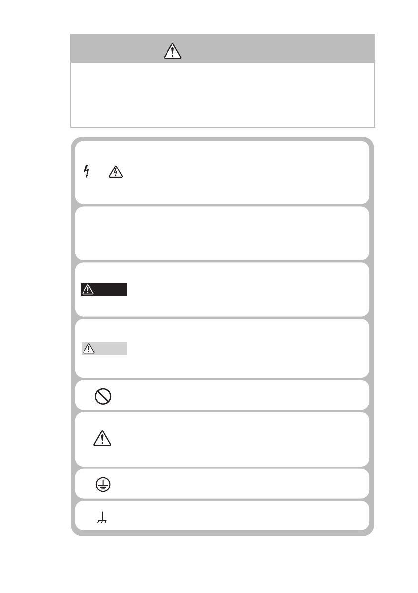
Saf ety Symbols
or the safe use and safe maintenance of this product, the
following symbols are used throughout this manual and on
the product. Understand the meanings of the symbols and
observe the instructions they indicate (the choice of sym
bols used depends on the products).
Indicates that a high voltage (over 1,000 V) is used here.
OR
Touching the part causes a possibly fatal electric shock. If
physical contact is required by your work, start work only
after you make sure that no voltage is output here.
-
DANGER
WARNING
CAUTION
Indicates an imminently hazardous situation which, if
ignored, will result in death or serious injury.
Indicates a potentially hazardous situation which, if
ignored, could result in death or serious injury.
Indicates a potentially hazardous situation which, if
ignored, may result in damage to the product and other
property.
Shows that the act indicated is prohibited.
Is placed before the sign "DANGER," "WARNING," or
"CAUTION" to emphasize these. When this symbol is
marked on the product, see the relevant sections in this
manual.
Indicates a protective conductor terminal.
Indicates a chassis(frame) terminal.
PAS SERIES Safety Symbols I
F
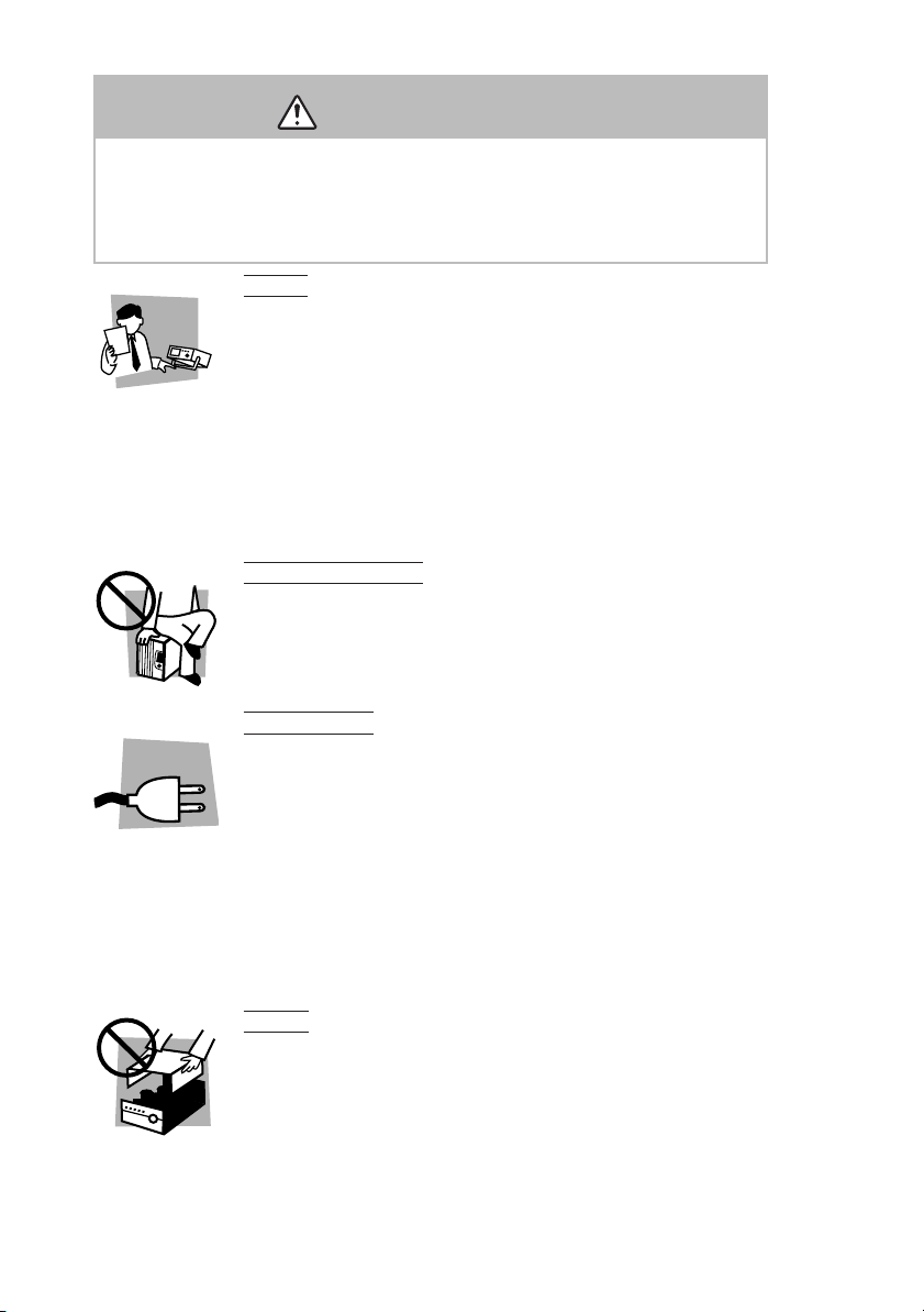
Saf ety Precautions
The f ollowing safety precautions must be observed to avoid
fire hazard, electrical shock, accidents, and other failures.
Keep them in mind and make sure that all of them are
observed properly.
User s
Operation
Manual
This product must be used only by qualified
personnel who understand the contents of this
operation manual.
• If it is handled by disqualified personnel, personal
injury may result. Be sure to handle it under
supervision of qualified personnel (those who have
electrical knowledge.)
• This product is not designed or produced for home-
use or use by general consumers.
Purposes of use
Do not use the product for purposes other than
those described in the operation manual.
Line
Voltage
Input po wer
Use the product with the specified input power
voltage.
• For applying power, use the AC power cord
provided. Note that the provided power cord is not
use with some products that can switch among
different input power voltages or use 100 V and 200
V without switching between them. In such a case,
use an appropriate power cord. For details, see the
relevant page of this operation manual.
ver
There are parts inside the product which may cause
physical hazards. Do not remove the external cover.
II Safety Precautions PAS SERIES
•
•
•
Co
•

Installation
GNL
•
When installing products be sure to observe "1.2
Precautions for installation" described in this
manual.
• To avoid electrical shock, connect the protective
ground terminal to electrical ground (safety ground).
• When applying power to the products from a
switchboard, be sure work is performed by a
qualified and licensed electrician or is conducted
under the direction of such a person.
• When installing products with casters, be sure to
lock the casters.
Relocation
•
Turn off the power switch and then disconnect all
cables when relocating the product.
• Use two or more persons when relocating the
product which weights more than 20 kg. The weight
of the products can be found on the rear panel of the
product and/or in this operation manual.
• Use extra precautions such as using more people
when relocating into or out of present locations
including inclines or steps. Also handle carefully
when relocating tall products as they can fall over
easily.
• Be sure the operation manual be included when the
product is relocated.
Check?
PAS SERIES
Operation
•
Check that the AC input voltage setting and the fuse
rating are satisfied and that there is no abnormality
on the surface of the AC power cord. Be sure to
unplug the AC power cord or stop applying power
before checking.
• If any abnormality or failure is detected in the
products, stop using it immediately. Unplug the AC
power cord or disconnect the AC power cord from
the switchboard. Be careful not to allow the product
to be used before it is completely repaired.
Safety Precautions III

•
For output wiring or load cables, use connection
cables with larger current capacity.
• Do not disassemble or modify the product. If it must
be modified, contact Kikusui agent/distributor.
Maintenance and c
•
To avoid electrical shock, be absolutely sure to
unplug the AC power cord or stop applying power
before performing maintenance or checking.
• Do not remove the cover when performing
maintenance or checking.
• To maintain performance and safe operation of the
product, it is recommended that periodic
maintenance, checking, cleaning, and calibration be
performed.
Ser
vice
•
Internal service is to be done by Kikusui service
engineers. If the product must be adjusted or
repaired, contact Kikusui agent/distributor.
hecking
IV Safety Precautions
PAS SERIES

Contents
Safety Symbols - - - - - - - - - - - - - - - - - - - - - - - - - - - - - - - - - - - - - - - - - - - I
Safety Precautions - - - - - - - - - - - - - - - - - - - - - - - - - - - - - - - - - - - - - - - - II
Preface
About this manual - - - - - - - - - - - - - - - - - - - - - - - - - - - - - - - - P-1
Outline of the PAS series - - - - - - - - - - - - - - - - - - - - - - - - - - - P-2
Options - - - - - - - - - - - - - - - - - - - - - - - - - - - - - - - - - - - - - - - P-3
Chapter1 Setup
1.1
Checking at unpacking
1.2
Precautions for installation
1.3
Precautions for moving
1.4
Connecting the AC power cord
1.5
Grounding
- - - - - - - - - - - - - - - - - - - - - - - - - - - - - - - - - - - - - - - - -
- - - - - - - - - - - - - - - - - - - - - - - - - - - - - - - -
- - - - - - - - - - - - - - - - - - - - - - - - - - - - -
- - - - - - - - - - - - - - - - - - - - - - - - - - - - - - - -
- - - - - - - - - - - - - - - - - - - - - - - - - - -
1-1
1-3
1-4
1-5
1-8
Chapter2
Chapter3
Before Using the Unit
2.1
Inrush Current
2.2
Load
- - - - - - - - - - - - - - - - - - - - - - - - - - - - - - - - - - - - - - - - - - - -
2.2.1
When Load Current Has Peaks or Is Pulse-Shaped
2.2.2
When the Load Generates a Reverse Current to the Power Supply
2.2.3
When the Load Has Accumulated Energy Such as Batteries
2.3
CV Power Supply and CC Power Supply
2.4
Alarm
- - - - - - - - - - - - - - - - - - - - - - - - - - - - - - - - - - - - - - - - - - - -
2.5
Grounding the Output Terminal
- - - - - - - - - - - - - - - - - - - - - - - - - - - - - - - - - - - - - -
- - - - - - - - - -
- - - - - - - - - - - - - - - - - - - -
- - - - - - - - - - - - - - - - - - - - - - - - -
Basic Operation
3.1
Turning on the Power
3.2
Basic Operation
3.2.1
Setting the Output
3.2.2
Setting the OVP (Overvoltage Protection) Trip Point
3.2.3
Setting the OCP (Overcurrent Protection) Trip Point
3.2.4
Unit Configuration (CONFIG)
3.2.5
Using the Unit as a Constant Voltage Power Supply
3.2.6
Using the Unit as a Constant Current Power Supply
3.3
Connecting the Load
3.3.1 Load Cable - - - - - - - - - - - - - - - - - - - - - - - - - - - - - - - - - - - 3-13
3.3.2 Connecting to the Output Terminals - - - - - - - - - - - - - - - - - - 3-16
3.4 Switching the Power Display - - - - - - - - - - - - - - - - - - - - - - - - - - - 3-19
- - - - - - - - - - - - - - - - - - - - - - - - - - - - - - - - -
- - - - - - - - - - - - - - - - - - - - - - - - - - - - - - - - - - - - -
- - - - - - - - - - - - - - - - - - - - - - - - - - - - - - - -
- - - - - - - -
- - - - - - - -
- - - - - - - - - - - - - - - - - - - - - - -
- - - - - - - -
- - - - - - - -
- - - - - - - - - - - - - - - - - - - - - - - - - - - - - - - - - 3-13
- - -
2-1
2-1
2-1
2-2
2-3
2-4
2-7
2-10
3-1
3-2
3-3
3-4
3-6
3-7
3-11
3-12
PAS SERIES V

3.5 LOCK Function - - - - - - - - - - - - - - - - - - - - - - - - - - - - - - - - - - - - 3-20
3.6 Remote Sensing - - - - - - - - - - - - - - - - - - - - - - - - - - - - - - - - - - - - 3-20
Chapter4 Remote Control
4.1 Analog Remote Control - - - - - - - - - - - - - - - - - - - - - - - - - - - - - - - -4-1
4.1.1 About the J1 Connector - - - - - - - - - - - - - - - - - - - - - - - - - - - -4-2
4.1.2 Controlling the Output Voltage Using External Voltage - - - - - -4-5
4.1.3 Controlling the Output Voltage Using External Resistance- - - - -4-8
4.1.4 Controlling the output current using external voltage - - - - - - - 4-11
4.1.5 Controlling the Output Current Using External Resistance - - - - 4-14
4.1.6 Controlling the Output ON/OFF Using External Contact - - - - -4-17
4.1.7 Controlling the Output Shutdown Using External Contact - - - - 4-19
4.2 Remote Monitoring - - - - - - - - - - - - - - - - - - - - - - - - - - - - - - - - - - 4-21
4.2.1 External Monitoring of the Output Voltage and Output Current 4-21
4.2.2 External Monitoring of the Operation Mode - - - - - - - - - - - - - 4-22
4.3 Digital Remote Control - - - - - - - - - - - - - - - - - - - - - - - - - - - - - - - 4-23
4.3.1 Connecting of the Power Supply Controller and
Device messages - - - - - - - - - - - - - - - - - - - - - - - - - - - - - - 4-23
Chapter5 Parallel and Series Operation
5.1 Master-Slave Series Operation - - - - - - - - - - - - - - - - - - - - - - - - - - -5-2
5.1.1 Functions during Master-Slave Series Operation - - - - - - - - - - -5-2
5.1.2 J1 Connector Connection (Series Operation) - - - - - - - - - - - - - -5-4
5.1.3 Load Connection for Series Operation - - - - - - - - - - - - - - - - - -5-5
5.1.4 Master-Slave Series Operation Setup - - - - - - - - - - - - - - - - - - -5-6
5.1.5 Master-Slave Series Operation Procedure - - - - - - - - - - - - - - - -5-7
5.2 Master-Slave Parallel Operation - - - - - - - - - - - - - - - - - - - - - - - - - -5-8
5.2.1 Functions during Master-Slave Parallel Operation - - - - - - - - - -5-8
5.2.2 J1 Connector Connection (Parallel Operation) - - - - - - - - - - - - 5-10
5.2.3 Load Connection for Parallel Operation - - - - - - - - - - - - - - - -5-11
5.2.4 Master-Slave Parallel Operation Setup - - - - - - - - - - - - - - - - - 5-13
5.2.5 Master-slave parallel Operation Procedure - - - - - - - - - - - - - - 5-14
Chapter6 Names and Functions of Controls
6.1 Front Panel - - - - - - - - - - - - - - - - - - - - - - - - - - - - - - - - - - - - - - - -6-1
6.2 Rear Panel - - - - - - - - - - - - - - - - - - - - - - - - - - - - - - - - - - - - - - - - -6-5
Chapter7 Maintenance
7.1 Cleaning - - - - - - - - - - - - - - - - - - - - - - - - - - - - - - - - - - - - - - - - - -7-1
7.1.1 Cleaning the Panels - - - - - - - - - - - - - - - - - - - - - - - - - - - - - - -7-1
7.1.2 Cleaning the Dust Filter - - - - - - - - - - - - - - - - - - - - - - - - - - - -7-2
VI PAS SERIES

7.2 Inspection - - - - - - - - - - - - - - - - - - - - - - - - - - - - - - - - - - - - - - - - - 7-8
7.3 Calibration - - - - - - - - - - - - - - - - - - - - - - - - - - - - - - - - - - - - - - - - 7-8
7.3.1 Test Equipment Required- - - - - - - - - - - - - - - - - - - - - - - - - - - 7-8
7.3.2 Environment - - - - - - - - - - - - - - - - - - - - - - - - - - - - - - - - - - - 7-9
7.3.3 Calibration Mode - - - - - - - - - - - - - - - - - - - - - - - - - - - - - - - 7-10
7.3.4 Calibration Procedure - - - - - - - - - - - - - - - - - - - - - - - - - - - - 7-11
7.4 Malfunctions and Causes- - - - - - - - - - - - - - - - - - - - - - - - - - - - - - 7-17
Chapter8 Specifications
Common Specifications- - - - - - - - - - - - - - - - - - - - - - - - - - - - 8-2
- - - - - - - - - - - - - - - - - - - - - - - - - - - - - - - - - - - - - - - - - - - - 8-7
350W Type Specifications - - - - - - - - - - - - - - - - - - - - - - - - - - 8-8
700W Type Specifications - - - - - - - - - - - - - - - - - - - - - - - - - 8-14
1 000W Type Specifications - - - - - - - - - - - - - - - - - - - - - - - - 8-20
Index
PAS SERIES VII

VIII PAS SERIES
Preface
About this manual
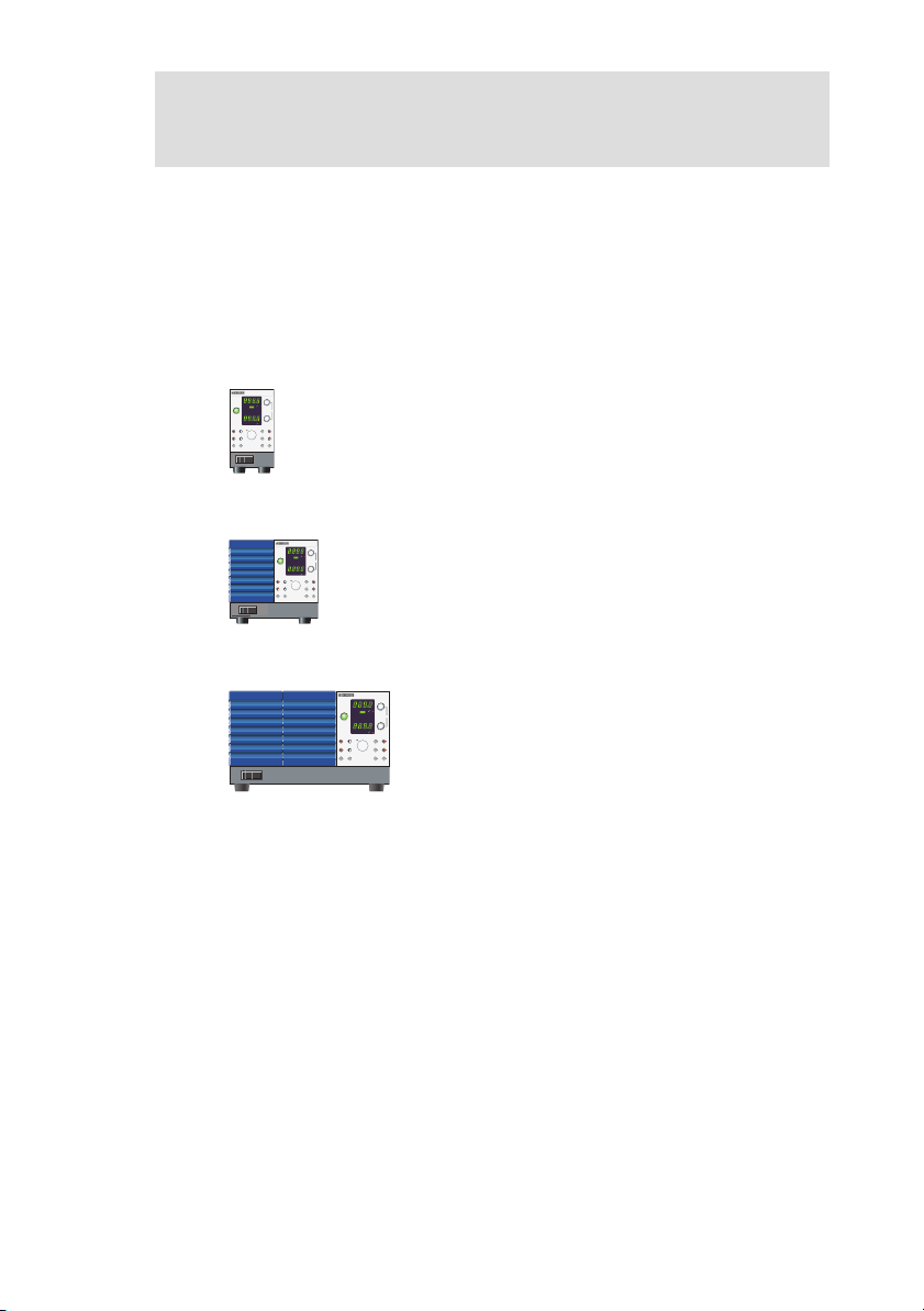
The PAS series is classified into three types depending on the output
capacity.
This operation manual describes the following models.
350W type
PAS10-35, PAS20-18, PAS40-9, PAS60-6, PAS80-4.5
REGULATED DC POWER SUPPLY
0-10V 35A
PAS10-35
VOLTAGE
OUTPUT
V W
CV
O N
PWR DSPL
OUTPUT
COARSE/FINE
CC
OFF
ALM
CURRENT
PAS160-2, PAS320-1, PAS500-0.6
PWR DSPL
A W
SHIFT
CONFIG
SET
ADDRESS
LOCK
OVP
OCP
700W type
REGULATED DC POWER SUPPLY
0-10V 70A
PAS10-70, PAS20-36, PAS40-18, PAS60-12, PAS80-9
PAS10-70
VOLTAGE
OUTPUT
V W
CV
O N
PWR DSPL
OUTPUT
COARSE/FINE
CC
OFF
ALM
CURRENT
PAS160-4, PAS320-2, PAS500-1.2
PWR DSPL
A W
SHIFT
CONFIG
SET
ADDRESS
LOCK
OVP
OCP
1000W type
REGULATED DC POWER SUPPLY
0-80V 13.5A
PAS80-13.5
PAS10-105, PAS20-54, PAS40-27, PAS60-18,
VOLTAGE
OUTPUT
V W
CV
O N
PWR DSPL
OUTPUT
COARSE/FINE
CC
OFF
ALM
CURRENT
PAS80-13.5, PAS160-6, PAS320-3,
PWR DSPL
A W
SHIFT
CONFIG
SET
ADDRESS
LOCK
OVP
PAS500-1.8
OCP
For details on the Power Supply Controller, see the operation manual
of the respective product. For connection to a Power Supply Controller and device messages. refer to the “Connecting & Programming
Guide” [Index.html] in the CD-ROM that came with the PIA4800
series.
Applicable firmware version of the PAS
This manual applies to PASs with firmware version 1.0x.
When contacting us about the product, please provide us the version
number and the manufacturing number that is affixed to the rear
panel.
For the procedure for checking the version, see "3.1 Turning on the
Power" .
PAS SERIES Preface P-1

Outline of the PAS series
The PAS series is a regulated DC power supply with a constant voltage/current automatic crossover function utilizing a switching regulator system. It is equipped with communication functions.
Features
■
P
(T
ower-factor improvement circuit
The po wer -f actor impro v ement circuit reduces the ef fects of har monic currents on the po wer line.
High effi ciency
The high po wer con v ersion ef fi cienc y reduces the cost of po wer and
the cost of heat radiation design during system confi guration.
Comm unication functions
Equipped with a digital remote control function through TP-B US
wist P air -B US) communication. (T otal length of TP-B US is 200
m.)
By combining with Kikusui's PIA4800 Series Po wer Supply Control ler , systemization for applications such as an automatic tester is pos sible.
Master-sla ve operation
Output v oltage or output current can be e xpanded by connecting mul tiple po wer supplies of the same model in series or in parallel and
controlling them with a single master de vice.
P-2 Preface PAS SERIES
Options
Belo w are options a v ailable for the P AS series.
or details on the options, contact your Kikusui agent or distrib utor .
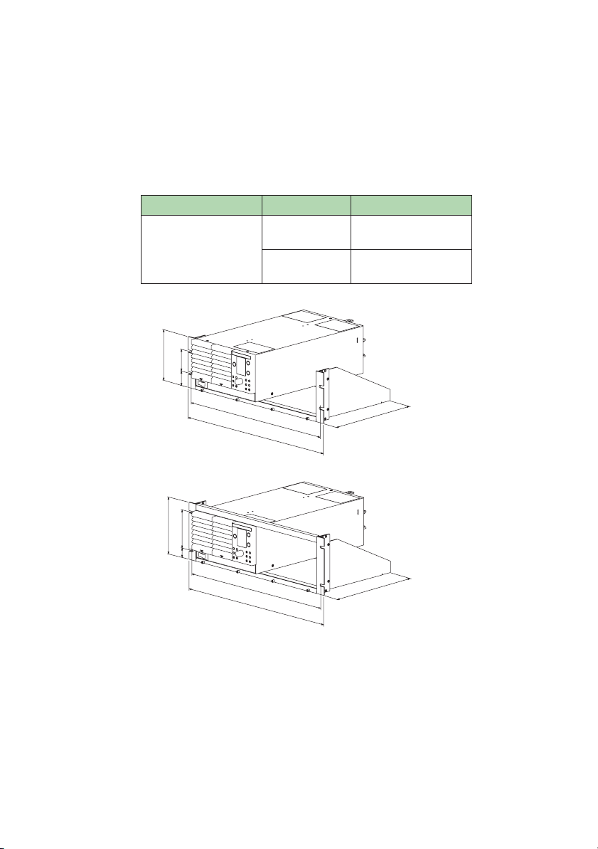
Rac k
able P-1 Rack mounting options
Product
Rack mount frame
57(2.24)
132.5(5.22)
37.75
(1.49)
149
100
24.5
460(18.11)
4
82
(18.9
460
480
Model
KRA3
KRA150
8)
Notes
Inch rack
EIA standard
Milli rack
JIS standard
KRA3
260(10.24)
KRA150
260
PAS SERIES
Fig.P-1 Rack mount frame
Unit: mm (inch)
Preface
P-3
F
T

Analog Remote Control Connector Kit (OP01-P
AS)
A kit for connecting to the J1 connector on the rear panel.
Component Quantity
Socket 1 pc.
Pins 10 pcs.
Protection cover 1 set
Chassis connection wire 1 pc.
Fig.P-2
Analog remote control connector kit
P-4 Preface
PAS SERIES
Chapter
This chapter describes the necessary procedure from unpacking to
preparation before use.
. 1 Setup
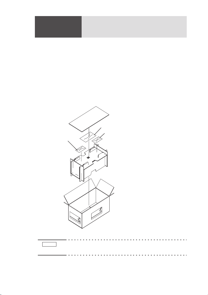
1.1
Checking at unpacking
When you receive the product, check that all accessories are included
and that the accessories have not been damaged during transportation.
If an
y of the accessories are damaged or missing, contact your
Kikusui agent /distrib
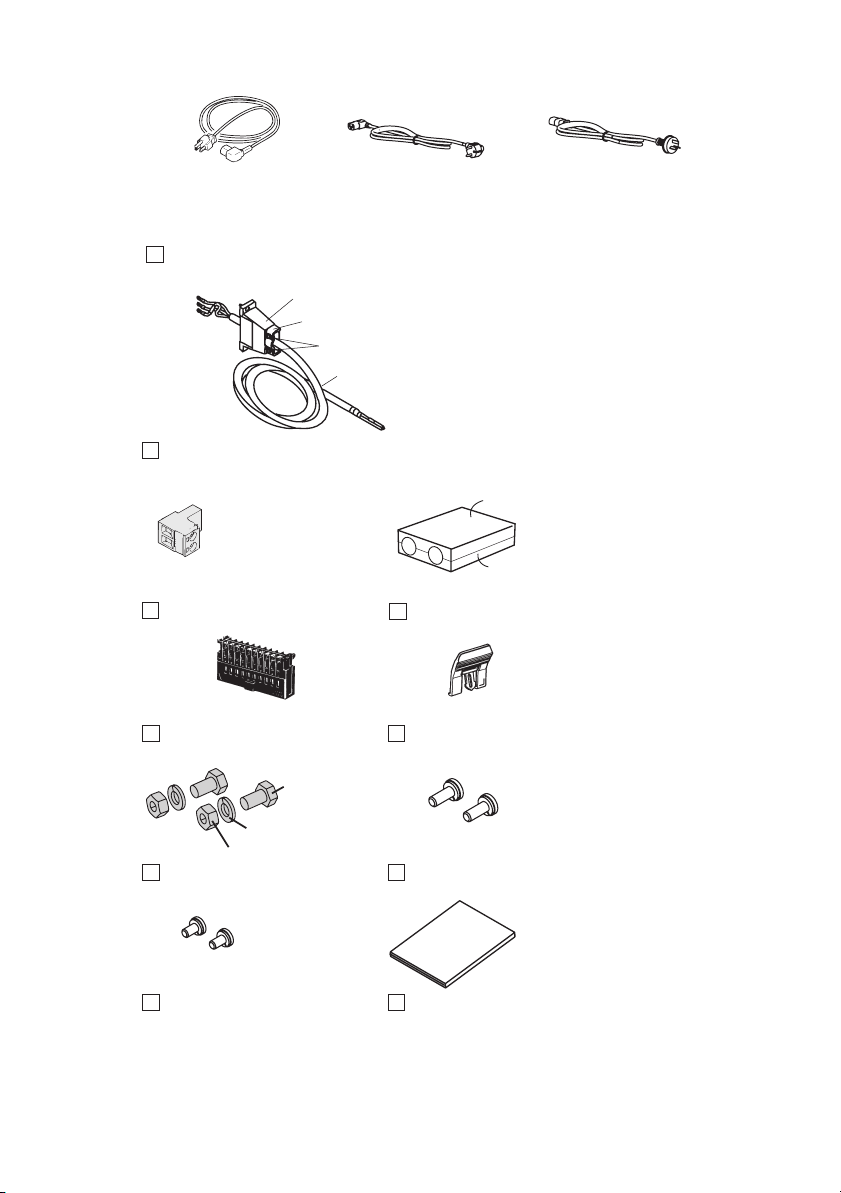
ACpowercord
utor
.
OperationManual
Accessories
NOTE
PAS SERIES
Fig.1-1
•
Packing/Unpacking (example for 700W type)
We recommend that all packing materials be saved, in case
the product needs to be transported at a later date.
Setup 1-1
or or
Rated voltage: 125 Vac
PLUG: NEMA5-15
[85-AA-0003] [85-AA-0005]
Rated voltage: 250 Vac
PLUG: CEE7/7
The power cord that is provided varies depending on
Power cord, 1 pc.
the destination for the product at the factory-shipment.
Cable clamp: [P1-000-055] 1 pc.
Fastening plate: [D6-750-001] 1 pc.
Accompanying screws B: [M3-112-017] 2 pcs.
Cable: [85-10-0630] 1 pc.
For products with CE Marking (CE mark
on the top cover), an EMI core
AC power cord for 1000W type
(with cable clamp and no plug)
[96-01-0180] is embedded in the AC
power cord for 1000W type.
Rated voltage: 250 Vac
PLUG: GB1002
[85-10-0790]
TOP
1 pc.
[84-61-5102]
TP-BUS connector
1 pc.
[84-49-0110]
J1 protection socket *1
2 sets
M8 output terminal screws
2 pcs.
[M3-112-012]
Sensing terminal screws*1
*1: Attached to the product.
Fig.1-2
1-2
Setup
[M1-100-011]
[M5-101-007]
[M4-100-007]
Accessories
BOTTOM
1 set
[Q1-500-077]
OUTPUT terminal cover
1 pc.
[83-06-5060]
J1 lock lever*1
2 pcs.
[M3-112-026]
M4 output terminal screws
1 copy
[Z1-002-402]
Operation manual
PAS SERIES

1.2
Precautions for installation
Be sure to observ
po
wer supply
Do not use the power supply in a flammable atmosphere.
■
T
o pre v ent e xplosion or fi re, do not use the po wer supply near alco hol, thinner , or other comb ustible materials, or in an atmosphere con taining such v apors.
■
Avoid locations where the power supply is exposed to
high temperatures or direct sunlight.
Do not locate the po wer supply near a heater or in areas subject to
drastic temperature changes.
Operating temperature range: 0°C to +50°C (+32°F to +122°F)
Storage temperature range: -25°C to +70°C (-13°F to +158°F)
Avoid humid environments.
■
Do not locate the po wer supply in a high-humidity en vironment—
near a boiler , humidifi er , or w ater supply .
Operating humidity range: 20% to 85% RH
Storage humidity range: 90% RH or less
Condensation may occur e v en within the operating humidity range.
In that case, do not start using the po wer supply until the location is
completely dry .
Do not place the power supply in a corrosive atmosphere.
■
Do not install the po wer supply in a corrosi v e atmosphere or one con taining sulfuric acid mist or the lik e. This may cause corrosion of v ar ious conductors and imperfect contact with connectors, leading to
malfunction and f ailure, or in the w orst case, a fi re.
■
Do not locate the power supply in a dusty environment.
Dirt and dust in the po wer supply may cause electrical shock or fi re.
.
e the follo
wing precautions when installing the
(no de w condensation is allo wed)
(no de w condensation is allo wed)
PAS SERIES
Setup 1-3

Do not use the power supply where ventilation is poor.
■
e
The po wer supply emplo ys a forced air cooling system. Air is tak en in
from intak e ports located on the po wer supply's sides and front, and is
xhausted from the rear . Prepare suf fi cient space around the po wer
supply so that the intak e ports and e xhaust port are al w ays completely
unobstructed. Otherwise, heat may accumulate in the po wer supply ,
resulting in fi re.
■
P
Do not place any object on the power supply.
articularly a hea vy one, as doing so could result in a malfunction.
Do not place the power supply on a tilted surface or in a
■
location subject to vibrations.
If placed on a non-le v el surf ace or in a location subject to vibration,
the po wer supply may f all, resulting in damage and injury .
Do not use the power supply in locations affected by
■
strong magnetic or electric fields.
Operation in a location subject to magnetic or electric fi elds may
cause the po wer supply to malfunction, resulting in electrical shock
or fi re.
1.3 Precautions for moving
When mo ving or transporting the po wer supply to an installation site,
observ e the follo wing precautions.
■ T
Mo
urn the PO WER switch off.
ving the po wer supply with the po wer on may result in electrical
shock or damage.
urn off the switch on the switchboard, and remove all
■ T
Mo
wirings connected.
ving the po wer supply with cables connected may break the cables
or cause the po wer supply to f all, resulting in injury .
For transportation, use the special packing material for the
■
T
power supply.
ransport the po wer supply in its original package to pre v ent vibra tion and f alls, which may damage the po wer supply . If you require
packing material, contact Kikusui agent/distrib utor .
1-4 Setup
PAS SERIES
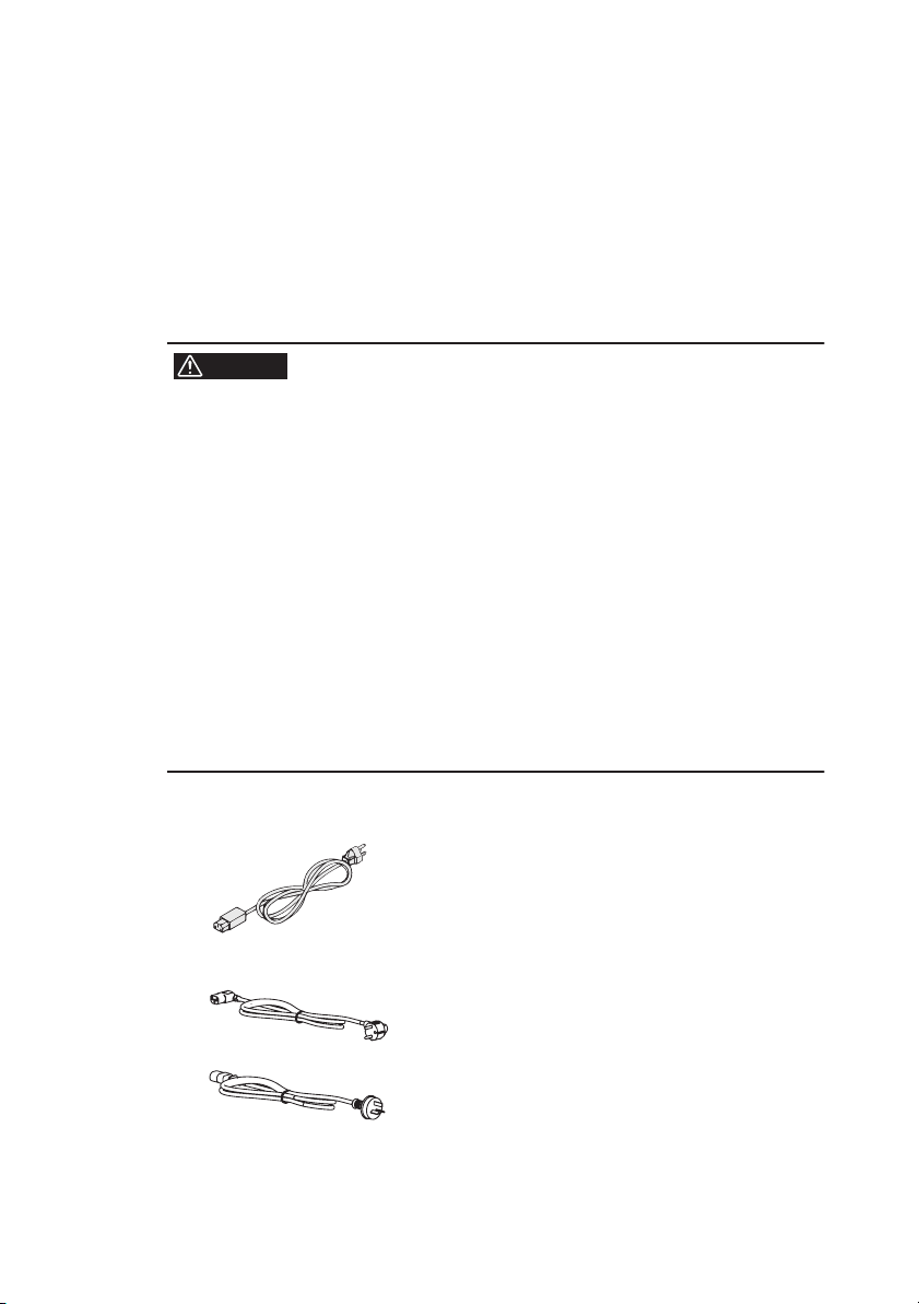
1.4 Connecting the AC power cord
The A C po wer cord pro vided with the product v aries depending on
the type.
or the connection procedure, see the respecti v e section for each type.
350W and 700W types
The A C po wer cord that is pro vided v aries depending on the destina tion for the product at the f actory-shipment.
WARNING
The power supply is designed to operate from the
overvoltage category II. Do not operate it from the
overvoltage category III or IV.
• The AC power cord for 100 V system shown in Fig.13 has a rated voltage of 125 VAC. If this AC power
cord is used at the line voltage of a 200 V system,
replace the AC power cord with that satisfying that
line voltage.
An appropriate AC power cord must be selected by
qualified personnel. If it is difficult to obtain the AC
power cord, consult your Kikusui distributor/agent.
• Secure adequate space around the power plug.
Do not insert the power plug to an outlet where
accessibility to the plug is poor. And, do not place
objects near the outlet that would result in poor
accessibility to the plug.
Do not use the AC power cord provided with the product as a AC
power cord for other instruments.
[85-AA-0004]
PLUG:NEMA5-15
Power cord for 100 V system
Rated voltage: 125 VAC
Rated current: 10 A
PAS SERIES
F
[85-AA-0005]
•
•
PLUG:CEE7/7
[85-10-0790]
PLUG:GB1002
Fig.1-3 AC power cord
Power cord for 200 V system
Rated voltage: 250 VAC
Rated current: 10 A
Setup 1-5

Connection procedure
Chec k that the supply v oltage is within the line v oltage
1.
r
ange of the po w er supply .
Input v oltage range: 100 V to 240 V A C
Frequenc y range: 50 Hz to 60 Hz
2.
T ur
n OFF the PO WER s witch.
Connect the A C po w er cord to the A C INPUT connector on
3.
the rear panel.
Use the pro vided po wer code or po wer code that is selected by qualifi ed
personnel.
Plug in the A C po w er cord.
4.
•
Direct connection to a s witchboard of 350W and 700W types
When directly connecting the product to a switchboard, k eep in mind
that the product is designed for Ov erv oltage Cate gory II.
Attach crimp terminals to the wires of the A C po wer cord when
directly connecting to a switchboard without using a plug.
WARNING
1-6 Setup
Connection of the AC power cord to the switchboard
must be carried out by qualified personnel.
• To prevent electric shock, turn OFF the switch on the
switchboard (to cut off the power feed from the
switchboard) and then connect the AC power cord.
• Install the AC power cord such that the distance
between the power supply and the switch on the
switchboard is within 3 m. This procedure facilitates
operation of the switch on the switchboard in the
event of emergency.
If the distance to the switch on the switchboard is to
be 3 m or more, install the AC power cord with a separate switch provided within 3 m from the power supply. For such a switch, use one with two poles that
can be disconnected simultaneously.
• For termination, attach crimp terminals that conform
to the terminal screws of the switchboard.
• Even if you cut the plug off the AC power cord,
observe the rated voltage of the AC power cord.
PAS SERIES

1000W type
The A C po wer cord that is included with the 1000W type can be used
on either a 100-V A C or 200-V A C system.
eep in mind that the product is designed for Ov erv oltage Cate gory II.
WARNING
CAUTION
Connection of the AC power cord to the switchboard
must be carried out by qualified personnel.
• To prevent electric shock, turn OFF the switch on the
switchboard (to cut off the power feed from the
switchboard) and then connect the AC power cord.
• Install the AC power cord such that the distance
K
•
between the power supply and the switch on the
switchboard is within 3 m. This procedure facilitates
operation of the switch on the switchboard in the
event of emergency.
If the distance to the switch on the switchboard is to
be 3 m or more, install the AC power cord with a separate switch provided within 3 m from the power supply. For such a switch, use one with two poles that
can be disconnected simultaneously.
• For termination, attach crimp terminals that conform
to the terminal screws of the switchboard.
• Inside the unit, protective circuits including input
fuses are connected to match the input terminal.
Make sure the colors of the wires connected to the
corresponding input terminals (L, N, and
(GND))
are correct.
Connection procedure
Chec k that the supply v oltage is within the line v oltage
1.
r
ange of the po w er supply .
Input v oltage range: 100 V to 240 V A C
Frequenc y range: 50 Hz to 60 Hz
2.
T ur
n OFF the PO WER s witch.
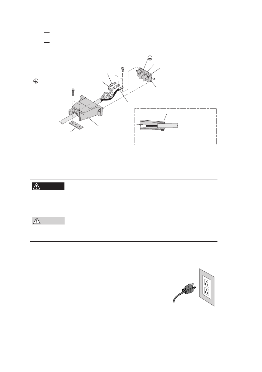
3.
Connect the pro vided A C po w er cord to the A C INPUT ter
minal board as sho wn in Fig.1-4 .
Attach cr imp ter minals to the A C po w er source side of the
A
4.
C po w er cord.
PAS SERIES
-
Setup 1-7
n OFF the s witchboard.
5.
T ur
6.
Connect the A C po w er cord to match the L, N, and GND of
the s witchboard.
N: White or blue
(GND): Green or green/yellow
Fastening plate
Fig.1-4 Connection of the AC power cord on the unit side
1.5 Grounding
•
Cable clamper
(GND)
N
L
AC INPUT terminal board
L: Black or brown
Fastening plate
Fix the covered part of the AC power
cord with the fastening plate.
WARNING
Electric shock may occur, if proper grounding is not
furnished.
• Connect the ground terminal to an electrical ground
(safety ground).
CAUTION
• If you do not ground the unit, malfunction may occur
due to external noise, or the noise generated by the
unit may become large.
Mak e sure to ground the unit for your safety.
350W and 700W types
Mak e sure to ground the unit.
Connect the 3-pin plug to a grounded 3-pin
receptacle.
1000W type
Mak e sure to connect the GND terminal of the A C INPUT terminal
block to the GND terminal of the switchboard.
1-8 Setup
PAS SERIES

Chapter . 2 Before Using the Unit
Before using the unit, users are requested to thoroughly understand
the follo wing matters.
F
fi
1.
2.1 Inrush Current
An inrush current fl o ws when the PO WER switch is turned on. If you
are planning to use se v eral sets of the unit in a system and turn on
their PO WER switches simultaneously , check that the A C po wer
source or the switchboard is of suf fi cient capacity .
or details on the inrush current of each model, see Chapter8 " Speci cations " .
•
CAUTION
Allo w at least 10 seconds between power cycles.
Repeated on/off of the POWER switch at short intervals can cause malfunction of the inrush current limiting circuit and shorten the service life of the input
fuse and POWER switch.
2.2 Load
Note that the output will become unstable if the follo wing types of
loads are connected.
When Load Current Has Peaks or Is Pulse-Shaped
When the Load Generates a Re v erse Current to the Po wer Supply
When the Load Has Accumulated Ener gy Such as Batteries
2.
3.
2.2.1 When Load Current Has Peaks or Is PulseShaped
The current meter on the unit indicates only mean v alues. Ev en when
the indicated v alue is less than the preset current v alue, the peak v al ues may actually e xceed the preset current v alue. In such case, the
unit is instantaneously put into constant-current operation mode, and
the output v
F
or these types of loads, you must increase the preset current v
increase the current capacity
PAS SERIES
oltage drops accordingly
.
.
Before Using the Unit 2-1
alue or
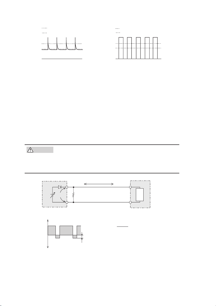
Preset constant current value
Meter indication value (mean value)
Preset constant current value
Meter indication value (mean value)
Fig.2-1
Load current with peaks
Fig.2-2 Pulse-shaped load cur-
rent
2.2.2
When the Load Generates a Reverse Current to the Power Supply
The unit cannot absorb a reverse current from a re
such as an inverter
po
wer supply
output will fl
F
or these types of loads, connect a resistor RD as sho
bypass the reverse current. However, the current capacity to the load
decreases by Irp.
•
CAUTION
F
for the power (allowing sufficient margin).
If a resistor with insufficient rated power for the circuit
is used, it may burn out.
EO
Equivalent circuit of the unit
+IO
0
Output current
waveform
-IO
Fig.2-3 Remedy for regenerative load
, converter
. Consequently
, or transformer that supplies current to a
, the output v
oltage will increase and the
uctuate.
or resistor RD, select an appropr
−
RD
Reverse current
IO
Irp
+
Regenerative load
RD[Ω] ≤
I
EO[V]
[A]
rp
R
D: Reverse current bypass dummy load
EO: Output voltage
Irp: Max. reverse current
wn in
iate resistor rated
Load
generative load
Fig.2-3
to
2-2 Before Using the Unit
PAS SERIES
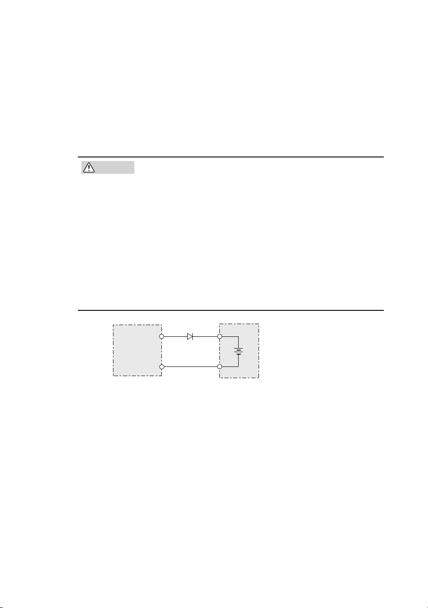
2.2.3
y
When the Load Has Accumulated Energy Such as Batteries
Connecting a load with accumulated energy, such as a battery
, to the
unit may cause current to flow from the load to the internal circuit of
the unit. This current may damage the unit or reduce the life of the
load.
For this type of loads, connect a reverse-current-prevention diode
(DRP) between the unit and the load in series as shown in Fig.2-4.
CAUTION
• To protect the load and the unit, select DRP according
to the following criteria.
1. Reverse voltage withstand capacity: At least twice
the rated output voltage of the unit.
2. Forward current capacity: Three to ten times the
rated output current of the unit.
3. A diode with small loss.
• Be sure to take into account the heat generated by
DRP. DRP may burn out with inadequate heat dissipa-
tion.
• Cannot be used in combination with remote sensing.
DRP
DRP: Reverse-current-prevention diode
PAS SERIES
Unit
Load with accumulated energ
Fig.2-4 Remedy against load with accumulated energy
Before Using the Unit 2-3

2.3 CV Power Supply and CC Power Supply
This unit is capable of both constant voltage and constant current
operation. This section describes these operations.
An ideal constant voltage power supply has zero output impedance at
all frequencies and maintains a constant voltage against all types of
load current variations. An ideal constant current power supply has
infinite output impedance at all frequencies and maintains constant
current by absorbing the load resistance variations by changing the
voltage.
Constant
Eo
OutputvoltageEo
00
Fig.2-5
Ideal constant voltage
power supply
Io
OutputcurrentIo OutputcurrentIo
Constant
Eo
OutputvoltageEo
Fig.2-6
Ideal constant current
power supply
Io
However, the output impedance of an actual constant voltage or constant current power supply is neither zero nor infinite and has a frequency response. In addition, since the output has limitations in terms
of maximum voltage and maximum current, power supplies are
unable to maintain a constant voltage or current for all types of load
current variations and load resistance variations. The following
describes the relationship between the basic operations in constant
voltage (CV) and constant current (CC) modes and the limit setting of
the unit.
The following description assumes a power supply with a DC output
of 100 V and 10 A (maximum rated output voltage of 100 V and maximum rated output current of 10A) as an example.
A resistive load of 10 Ω is connected to the output terminals of the
power supply, and the output current limit is set to 5 A. In this condition, the output voltage is raised gradually from 0 V. At this point, the
power supply is operating in the constant voltage (CV) mode. The
2-4 Before Using the Unit PAS SERIES
output current increases as the output voltage increases. When the
output voltage reaches 50 V (that is, the output current has reached 5
A), the output voltage no longer increases even if you attempt to raise
it. This is because the output current is limited to 5 A specified initially, causing the power supply to switch to the constant current (CC)
operation mode. In this way, the power supply automatically switches
from the constant voltage to constant current operation to prevent an
overcurrent from flowing. (The point at which the operation mode
switches is called the "crossover point".) If the current limit is raised
in this condition, the power supply returns to the previous constant
voltage operation, allowing you to increase the output voltage further.
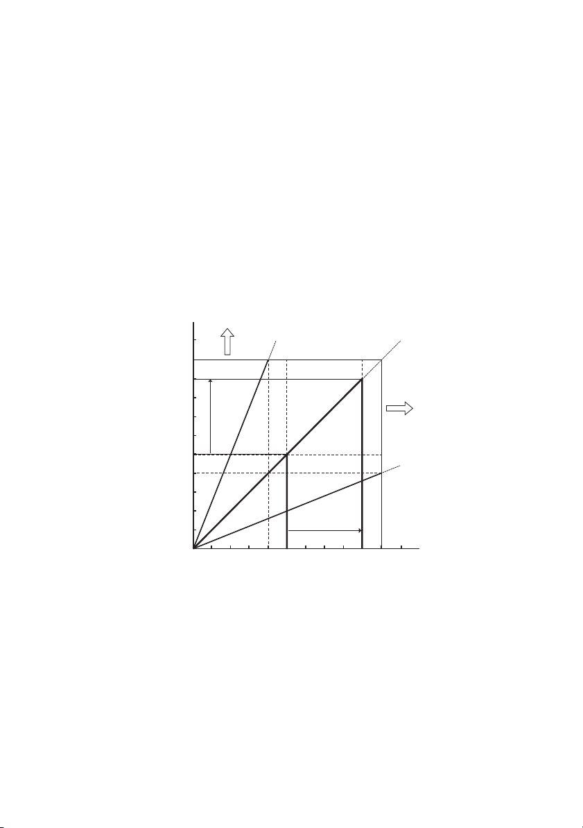
If the current limit is increased from 5 A to 9 A in Fig.2-7, a voltage
of up to 90 V can be output.
Areawherevoltage
needstobeincreased
Load line of RL = 25 Ω
100 V
90 V
Load line of RL = 10 Ω
Areawherecurrent
capacityneedstobe
increased
50 V
40 V
OutputvoltageEo
0 5 A 10 A9 A4 A
OutputcurrentIo
Load line of RL = 4 Ω
Fig.2-7 Constant voltage operation and constant current
operation
Next, let's assume the case in which a load resistance of 4 Ω is used.
The output current limit is considered to be the rated maximum output current. If you increase the output voltage from 0 V, the output
current reaches the output current limit when the output voltage
reaches 40 V; the power supply cannot output a voltage above 40 V.
This is the limit even though the power supply is generating less than
PAS SERIES Before Using the Unit 2-5

half its output capacity in terms of power. If you wish to increase the
output voltage further, the unit needs to be replaced by a model having larger current capacity. Particularly for loads into which a transient peak current flows, the current must be set such that its peak
does not reach (or exceed) the current limit. If the unit enters constant
current operation mode even when the current is set to the rated output current, the current capacity needs to be raised.
Next, we consider a case in which a load resistance of 25 Ω is used.
In this case, if the output current limit is set to 4 A or more, the power
supply can output voltages from 0 V to the rated maximum output
voltage in the constant voltage operation mode. The output voltage
limit is set to the rated maximum output voltage under this load condition, and the output current is gradually increased from 0 A. At this
point, the power supply is operating in the constant current (CC)
mode. The output voltage increases as the output current increases.
When the output voltage reaches 100 V, the output current no longer
increases even if you attempt to raise it. If you wish to increase the
current flow further in this condition, the unit needs to be replaced by
a model having higher output voltage. Particularly for loads that generate transient surge voltage, the voltage must be set so that the surge
voltage does not reach (or exceed) the voltage limit.
2-6 Before Using the Unit PAS SERIES

2.4 Alarm
The unit is equipped with the following protection function. When the
protection function is activated, "ALM" on the front panel display
lights, and the OUTPUT is turned off or the POWER switch is shut
down. However, the only action available when OHP is activated is
turning off the OUTPUT. (See Fig.2-8.)
In addition, an ALARM signal is output to pin 20 of the J1 connector
when the protection function is activated. (See Fig.2-9.)
For details on selecting whether to turn off the OUTPUT or shut
down the POWER switch when an alarm is activated, see "3.2.4 Unit
Configuration (CONFIG)".
When POWER switch shutdown is selected, the illumination of
"ALM" and the ALARM signal output is held for approximately 0.5 s.
Recovery from an alarm
• When POWER switch shut down is selected
After clearing the abnormal condition that caused the alarm, turn
on the POWER switch.
• When OUTPUT OFF is selected
Turn off the POWER switch, clear the abnormal condition that
caused the alarm, and turn on the POWER switch.
Protection Function
■
•
F
OVP (overvoltage protection)
The o v erv oltage protection function protects a load from une xpect edly high v oltage. The function is acti v ated when the v oltage e xceeds
a preset v oltage (O VP trip point).
Selectable range: 10 % to 110 % of the rated output v oltage.
If the O VP function is acti v ated when CONFIG is set to OUTPUT
OFF , the v oltage display sho ws "O VP ."
or details, see "3.2.2 Setting the O VP (Ov erv oltage Protection) T rip
Point " .
PAS SERIES Before Using the Unit 2-7

OCP (overcurrent protection)
CV
OUTPUT
OFF
ALM
V/
W
A/
W
CC
ON
The o v ercurrent protection function protects a load from une xpect edly high current. The function is acti v ated when the current e xceeds
a preset current (OCP trip point).
Selectable range: 10 % to 110 % of the rated output current.
If the OCP function is acti v ated when CONFIG is set to OUTPUT
OFF , the v oltage display sho ws "OCP ."
or details, see "3.2.3 Setting the OCP (Ov ercurrent Protection) T rip
Point " .
OHP (Overheat Protection)
This function is acti v ated when the internal temperature of the unit
raises abnormally .
This function protects the unit from the follo wing conditions.
When the unit is used in an environment exceeding the operation temperature range
• When the unit is used with the inlet or exhaust port blocked
• When the fan motor stops
If the OHP function is activated, the voltage display shows "OHP".
If the condition that caused the OHP to be activated is not corrected,
the OHP function is activated again when the POWER switch is
turned on.
•
F
•
•
CV
CC
Fig.2-8 ALARM indication example (OHP)
2-8 Before Using the Unit
ON
OUTPUT
OFF
V/
ALM
A/
PAS SERIES
 Loading...