

Kikusui PAS 10-70, PAS 160-2, PAS 20-36, PAS 40-18, PAS 20-18 User Manual
...
Part No. IA005084
Jan. 2017
USER’S MANUAL
Regulated DC Power Supply
PAS Series
PAS 10-35
PAS 20-18
PAS 40-9
PAS 60-6
PAS 80 -4.5
PAS 160-2
PAS 320-1
PAS 500-0.6
PAS 10-70
PAS 20-36
PAS 40-18
PAS 60-12
PAS 80 -9
PAS 160-4
PAS 320-2
PAS 500-1.2
PAS 10-105
PAS 20-54
PAS 40-27
PAS 60-18
PAS 80 -13.5
PAS 160-6
PAS 320-3
PAS 500-1.8
350W Type
700W Type
1000W Type

About the Documentation
These manuals are intended for users of the
Regulated DC Power Supply and their
instructors. It is assumed that the r ea der has
knowledge about electrical aspects of
regulated DC power supplies.
Documentation Structure
User’s manual (This manual, PDF)
This manual is intended for first-time users of
this product. It provides an overview of the
product and notes on usage. It also explains
o configure the product, operate the
how t
product, perform maintenance on the product,
and so on.
To effectively use the product features, read
this man
ual from beginning to end.
This manual is designed to be read from
beginning to end. We recommend that you
read it thoroughly before using this product for
the first time.
If you forget how to use the product or if a
problem occurs, we recommend that you refer
to this manual again.
Setup Guide
This guide is intended for first-time users of
the product. It gives an overview of the
product, connecting procedures, etc. Please
read through and understand this guide
before operating the product.
Quick Reference
The quick reference briefly explains the panel
description and the basic operation of the
product.
Connecting & Programming Guide
(HTML, PDF)
This manual contains details about remote
control.
This is written for readers with sufficient basic
knowledge of how to control instruments
using a personal computer.
Safety information
This document contains general safety
precautions for this product. Keep them in
mind and make sure to observe them.
If you find any misplaced or missing pages in
the manuals, they will be replaced. If the
manual gets lost or soiled, a new c op y ca n be
provided for a fee. To replace or purchase a
manual, please contact your Kikusui agent or
distributor. At that time, inform your agent or
distributor of the “Part No.” written on the front
cover of this manual.
Every effort has been made to ensure the
racy of this manual. However, if you have
accu
any ques
please contact your Kikusui agent or
distributor.
After you have finished reading this manual,
store it
any time.
tions or find any errors or omissi on s,
so that you can use it for reference at
Firmware versions that this manual
covers
This manual covers firmware versions 1.0X.
When contacting us about the product, please
provide us with:
The model (marked in the top section of
the front panel)
The firmware version (see page P-1)
The serial number (marked on the rear
panel)
Trademarks
Microsoft, Windows, and Visual Basic are
registered trademarks of Microsoft
Corporation in the United States and/or other
countries.
All company names and product names used
s manual are trademarks or registered
in thi
trademarks of their respective companies.
Copyrights
The contents of this manual may not be
reproduced, in whole or in part, without the
prior consent of the copyright holder.
The specifications of this product and the
content
s of this manual are subject to change
without prior notice.
PDF and HTML are included on attached CD-
ROM.
Adobe Reader is required to view the PDF
files. Microsoft Internet Explorer or Google
Chrome is required to view the HTML files.
© 2011 Kikusui Electronics Corporation
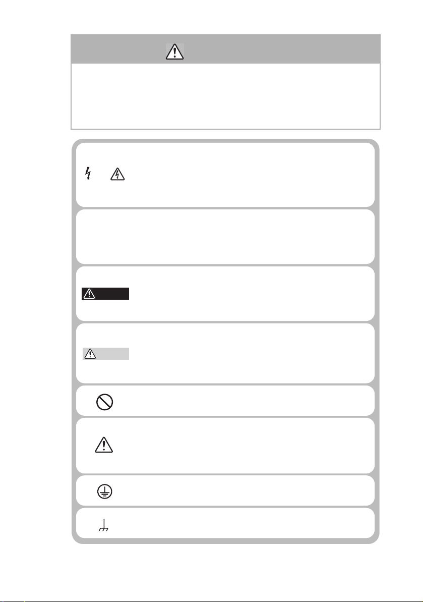
Indicates that a high voltage (over 1,000 V) is used here.
Touching the part causes a possibly fatal electric shock. If
physical contact is required by your work, start work only
after you make sure that no voltage is output here.
Indicates an imminently hazardous situation which, if
ignored, will result in death or serious injury.
Indicates a potentially hazardous situation which, if
ignored, could result in death or serious injury.
Indicates a potentially hazardous situation which, if
ignored, may result in damage to the product and other
property.
Shows that the act indicated is prohibited.
Is placed before the sign “DANGER,” “WARNING,” or
“CAUTION” to emphasize these. When this symbol is
marked on the product, see the relevant sections in this
manual.
Indicates a protective conductor terminal.
Indicates a chassis(frame) terminal.
OR
WARNING
COUTION
DANGER
Safety Symbols
For the safe use and safe maintenance of this product, the
following symbols are used throughout this manual and on
the product. Understand the meanings of the symbols and
observe the instructions they indicate (the choice of symbols
used depends on the products).
PASSERIES SafetySymbols I
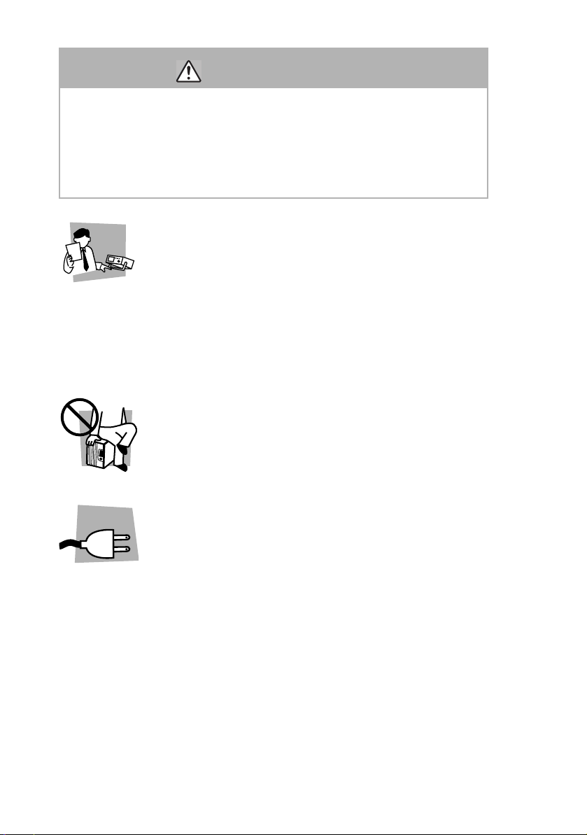
Safety Precautions
Operation
Manual
Line
Voltage
The following safety precautions must be observed to avoid
fire hazard, electrical shock, accidents, and other failures.
Keep them in mind and make sure that all of them are
observed properly. Using the product in a manner that is not
specified in this manual may impair the protection functions
provided by the product.
Users
• This product must be used only by qualified
personnel who understand the contents of this
manual.
• If it is handled by disqualified personnel, personal
may result. Be sure to handle it under
injury
supervision of qualified personnel (those who have
electrical knowledge.)
• This product is not designed or produced for home-
use or use by
Purposes of use
• Do not use the product for purposes other than
those described in the manual.
general consumers.
Input power
• Use the product with the specified input power
voltage.
• For applying power, use the AC power cord
prov
ided. Note that the provided power cord is not
use with some products that can switch among
different input power voltages or use 100 V and 200
V without switching between them. In such a case,
use an appropriate power cord. For details, see the
relevant page of this manual.
II SafetyPrecautions PASSERIES

Cover
GNL
• There are parts inside the product which may cause
physical hazards. Do not remove the external cover.
Installation
• When installing products be sure to observe "1.2
Precautions for installation" described in this
manual.
• To avoid electrical shock, connect the protective
nd terminal to electrical ground (safety ground).
grou
• When applying power to the products from a
switch
board, be sure work is performed by a
qualified and licensed electrician or is conducted
under the direction of such a person.
• When installing products with casters, be sure to
lock the casters.
Relocation
• Turn off the power switch and then disconnect all
cables when relocating the product.
• Use two or more persons when relocating the
pro
duct which weights more than 18 kg. The weight
of the products can be found on the rear panel of the
product and/or in this manual.
• Use extra precautions such as using more people
when re
including inclines or steps. Also handle carefully
when relocating tall products as they can fall over
easily.
• Be sure the manual be included when the product is
reloca
locating into or out of present locations
ted.
PAS SERIES Safety Precautions III

Operation
Check?
• Check that the AC input voltage setting and the fuse
rating are satisfied and that there is no abnormality
on the surface of the AC power cord. Be sure to
unplug the AC power cord or stop applying power
before checking.
• If any abnormality or failure is detected in the
products
, stop using it immediately. Unplug the AC
power cord or disconnect the AC power cord from
the switchboard. Be careful not to allow the product
to be used before it is completely repaired.
• For output wiring or load cables, use connection
es with larger current capacity.
cabl
• Do not disassemble or modify the product. If it must
be modif
ied, contact Kikusui agent/distributor.
Maintenance and checking
• To avoid electrical shock, be absolutely sure to
unplug the AC power cord or stop applying power
before performing maintenance or checking.
• Do not remove the cover when performing
maintena
nce or checking.
• To maintain performance and safe operation of the
product,
it is recommended that periodic
maintenance, checking, cleaning, and calibration be
performed.
Service
• Internal service is to be done by Kikusui service
engineers. If the product must be adjusted or
repaired, contact Kikusui agent/distributor.
IV Safety Precautions PAS SERIES

Contents
Safety Symbols - - - - - - - - - - - - - - - - - - - - - - - - - - - - - - - - - - - - - - - - - - -I
Safety Precautions - - - - - - - - - - - - - - - - - - - - - - - - - - - - - - - - - - - - - - - - II
Preface
About this manual - - - - - - - - - - - - - - - - - - - - - - - - - - - - - - - P-1
Outline of the PAS series - - - - - - - - - - - - - - - - - - - - - - - - - - - P-2
Options - - - - - - - - - - - - - - - - - - - - - - - - - - - - - - - - - - - - - - - P-3
Chapter1 Setup
1.1 Checking at unpacking - - - - - - - - - - - - - - - - - - - - - - - - - - - - - - - - 1-1
1.2 Precautions for installation - - - - - - - - - - - - - - - - - - - - - - - - - - - - - 1-3
1.3 Connecting the AC power cord- - - - - - - - - - - - - - - - - - - - - - - - - - - 1-3
Chapter2 Before Using the Unit
2.1 Inrush Current - - - - - - - - - - - - - - - - - - - - - - - - - - - - - - - - - - - - - - 2-1
2.2 Load - - - - - - - - - - - - - - - - - - - - - - - - - - - - - - - - - - - - - - - - - - - - 2-1
2.2.1 When Load Current Has Peaks or Is Pulse-Shaped- - - - - - - - - - 2-1
2.2.2 When the Load Generates a Reverse Current to the Power Supply2-2
2.2.3 When the Load Has Accumulated Energy Such as Batteries - - - 2-3
2.3 CV Power Supply and CC Power Supply - - - - - - - - - - - - - - - - - - - - 2-4
2.4 Alarm- - - - - - - - - - - - - - - - - - - - - - - - - - - - - - - - - - - - - - - - - - - - 2-7
2.5 Grounding the Output Terminal - - - - - - - - - - - - - - - - - - - - - - - - - 2-10
Chapter3 Basic Operation
3.1 Turning on the Power - - - - - - - - - - - - - - - - - - - - - - - - - - - - - - - - - 3-1
3.2 Basic Operation - - - - - - - - - - - - - - - - - - - - - - - - - - - - - - - - - - - - - 3-2
3.2.1 Setting the Output- - - - - - - - - - - - - - - - - - - - - - - - - - - - - - - - 3-3
3.2.2 Setting the OVP (Overvoltage Protection) Trip Point - - - - - - - - 3-4
3.2.3 Setting the OCP (Overcurrent Protection) Trip Point - - - - - - - - 3-6
3.2.4 Unit Configuration (CONFIG) - - - - - - - - - - - - - - - - - - - - - - - 3-7
3.2.5 Using the Unit as a Constant Voltage Power Supply- - - - - - - - 3-11
3.2.6 Using the Unit as a Constant Current Power Supply- - - - - - - - 3-12
3.3 Connecting the Load- - - - - - - - - - - - - - - - - - - - - - - - - - - - - - - - - 3-13
3.3.1 Load Cable - - - - - - - - - - - - - - - - - - - - - - - - - - - - - - - - - - - 3-13
3.3.2 Connecting to the Output Terminals - - - - - - - - - - - - - - - - - - 3-15
3.4 Switching the Power Display - - - - - - - - - - - - - - - - - - - - - - - - - - - 3-18
3.5 LOCK Function - - - - - - - - - - - - - - - - - - - - - - - - - - - - - - - - - - - - 3-19
3.6 Remote Sensing - - - - - - - - - - - - - - - - - - - - - - - - - - - - - - - - - - - - 3-19
PASSERIES V

Chapter4 Remote Control
4.1 Analog Remote Control - - - - - - - - - - - - - - - - - - - - - - - - - - - - - - - -4-1
4.1.1 About the J1 Connector - - - - - - - - - - - - - - - - - - - - - - - - - - - - 4-2
4.1.2 Controlling the Output Voltage Using External Voltage - - - - - -4-5
4.1.3 Controlling the Output Voltage Using External Resistance- - - - -4-8
4.1.4 Controlling the output current using external voltage - - - - - - - 4-11
4.1.5 Controlling the Output Current Using External Resistance- - - - 4-14
4.1.6 Controlling the Output ON/OFF Using External Contact - - - - - 4-17
4.1.7 Controlling the Output Shutdown Using External Contact - - - - 4-19
4.2 Remote Monitoring - - - - - - - - - - - - - - - - - - - - - - - - - - - - - - - - - - 4-21
4.2.1 External Monitoring of the Output Voltage and Output Current 4-21
4.2.2 External Monitoring of the Operation Mode - - - - - - - - - - - - - 4-22
4.3 Digital Remote Control - - - - - - - - - - - - - - - - - - - - - - - - - - - - - - - 4-23
4.3.1 Connecting of the Power Supply Controller and Device messages
- - - - - - - - - - - - - - - - - - - - - - - - - - - - - - - - - - - - - - - - - - 4-23
Chapter5 Parallel and Series Operation
5.1 Master-Slave Series Operation - - - - - - - - - - - - - - - - - - - - - - - - - - -5-2
5.1.1 Functions during Master-Slave Series Operation - - - - - - - - - - -5-2
5.1.2 J1 Connector Connection (Series Operation) - - - - - - - - - - - - - - 5-4
5.1.3 Load Connection for Series Operation - - - - - - - - - - - - - - - - - -5-5
5.1.4 Master-Slave Series Operation Setup - - - - - - - - - - - - - - - - - - -5-6
5.1.5 Master-Slave Series Operation Procedure - - - - - - - - - - - - - - - - 5-7
5.2 Master-Slave Parallel Operation - - - - - - - - - - - - - - - - - - - - - - - - - - 5-8
5.2.1 Functions during Master-Slave Parallel Operation - - - - - - - - - -5-8
5.2.2 J1 Connector Connection (Parallel Operation) - - - - - - - - - - - - 5-10
5.2.3 Load Connection for Parallel Operation - - - - - - - - - - - - - - - - 5-11
5.2.4 Master-Slave Parallel Operation Setup - - - - - - - - - - - - - - - - - 5-13
5.2.5 Master-slave parallel Operation Procedure - - - - - - - - - - - - - - 5-14
Chapter6 Names and Functions of Controls
6.1 Front Panel - - - - - - - - - - - - - - - - - - - - - - - - - - - - - - - - - - - - - - - - 6-1
6.2 Rear Panel - - - - - - - - - - - - - - - - - - - - - - - - - - - - - - - - - - - - - - - - - 6-5
Chapter7 Maintenance
7.1 Cleaning - - - - - - - - - - - - - - - - - - - - - - - - - - - - - - - - - - - - - - - - - - 7-1
7.1.1 Cleaning the Panels - - - - - - - - - - - - - - - - - - - - - - - - - - - - - - - 7-1
7.1.2 Cleaning the Dust Filter - - - - - - - - - - - - - - - - - - - - - - - - - - - - 7-2
7.2 Inspection - - - - - - - - - - - - - - - - - - - - - - - - - - - - - - - - - - - - - - - - - 7-8
7.3 Calibration- - - - - - - - - - - - - - - - - - - - - - - - - - - - - - - - - - - - - - - - -7-8
7.3.1 Test Equipment Required - - - - - - - - - - - - - - - - - - - - - - - - - - - 7-8
VI PAS SERIES

7.3.2 Environment - - - - - - - - - - - - - - - - - - - - - - - - - - - - - - - - - - - 7-9
7.3.3 Calibration Mode - - - - - - - - - - - - - - - - - - - - - - - - - - - - - - - 7-10
7.3.4 Calibration Procedure - - - - - - - - - - - - - - - - - - - - - - - - - - - - 7-11
7.4 Malfunctions and Causes- - - - - - - - - - - - - - - - - - - - - - - - - - - - - - 7-17
Chapter8 Specifications
Common Specifications- - - - - - - - - - - - - - - - - - - - - - - - - - - - 8-2
350W Type Specifications - - - - - - - - - - - - - - - - - - - - - - - - - - 8-8
700W Type Specifications - - - - - - - - - - - - - - - - - - - - - - - - - 8-14
1 000W Type Specifications - - - - - - - - - - - - - - - - - - - - - - - - 8-20
Index
PAS SERIES VII

This page has been intentionally left blank.
VIII PAS SERIES
Preface
V W
A W
OUTPUT
OUTPUT
VOLTAGE
CURRENT
CONFIG
SET
ADDRESS
LOCK
COARSE/FINE
OVP
PWR DSPL
PWR DSPL
OCP
SHIFT
ON
CC
CV
OFF
ALM
REGULATED DC POWER SUPPLY
PAS10-35
0-10V 35A
V W
A W
OUTPUT
OUTPUT
VOLTAGE
CURRENT
CONFIG
SET
ADDRESS
LOCK
COARSE/FINE
OVP
PWR DSPL
PWR DSPL
OCP
SHIFT
O N
CC
CV
OFF
ALM
REGULATED DC POWER SUPPLY
PAS10-70
0-10V70A
V W
A W
OUTPUT
OUTPUT
VOLTAGE
CURRENT
CONFIG
SET
ADDRESS
LOCK
COARSE/FINE
OVP
PWR DSPL
PWR DSPL
OCP
SHIFT
O N
CC
CV
OFF
ALM
REGULATED DC POWER SUPPLY
PAS80-13.5
0-80V13.5A
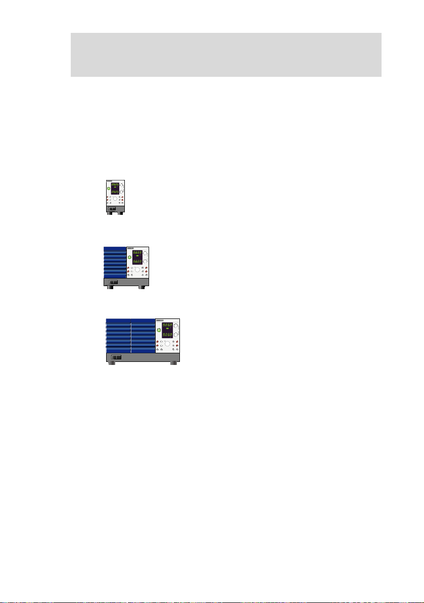
About this manual
The PAS series is classified into three types depending on the output
capacity.
This manual describes the following models.
350W type
PAS10-35, PAS20-18, PAS40-9, PAS60-6, PAS80-4.5
PAS 1 6 0-2 , PAS3 2 0- 1, PA S 500 - 0 .6
700W type
PAS10-70, PAS20-36, PAS40-18, PAS60-12, PAS80-9
PAS160-4, PAS320-2, PAS500-1.2
1000W type
PAS10-105, PAS20-54, PAS40-27, PAS60-18,
PAS80-13.5, PAS160-6, PAS320-3,
PAS500-1.8
For details on the Power Supply Controller, see the operation manual
of the respective product. For connection to a Power Supply Controller and device messages. refer to the “Connecting & Programming
Guide” [Index.html] in the CD-ROM.
Applicable firmware version of the PAS
This manual applies to PASs with firmware version 1.0x.
When contacting us about the product, please provide us the version
number and the manufacturing number that is affixed to the rear
panel.
For the procedure for checking the version, see "3.1 Turning on the
Power" .
PAS SERIES Preface P-1

Outline of the PAS series
The PAS series is a regulated DC power supply with a constant voltage/current automatic crossover function utilizing a switching regulator system. It is equipped with communication functions.
■ Features
wer-factor improvement circuit
Po
The power-factor improvement circuit reduces the effects of har-
nic current
mo
High efficiency
The high power conversion efficiency reduces the cost of power and
the cost of heat radi
Communication functions
Equipped with a digital remote control function through TP-BUS
wist Pa
(T
By combining with Kikusui's PIA4800 Series Power Supply Controller, systemization for applications such as an automatic tester is possible.
Master-slave operation
Output voltage or output current can be expanded by connecting mul-
ple power su
ti
controlling them with a single master device.
s on the power line.
ation design du
ir-BUS) communication. (Total length of TP-BUS is 200 m.)
pplies of the same model in series or in parallel and
ring system configuration.
P-2 Preface PAS SERIES
Options
KRA150
Milli rack JIS standard
460
480
460(18.11)
482(18.98)
149
24.5
100
57(2.24)
260(10.24)
260
37.75
(1.49)
KRA3
Inch rack EIA standard
Unit: mm (inch)
NOTE
Below are options available for the PAS series.
For details on the options, contact your Kikusui agent or distributor.
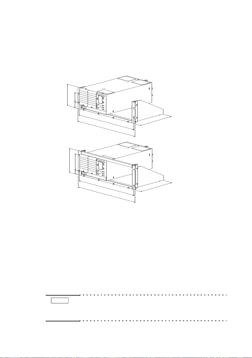
Rack adapter
132.5(5.22)
Fig.P-1 Rack adapter
For information on rack adapter mounting, see the KRA3 or KRA150
operation manual.
Remove the handle and rubber feet before you mount the PAS series
to a rack.
We recommend that you keep all pieces that you have removed from
the PAS series. You will need these pieces if you remove the PAS
series from the rack adapter.
If you remove the PAS series from the rack, re-attach the original rubber feet.
• To reinstall the handle that has been removed, use screw
locking agent (e.g., 1401B by ThreeBond International, Inc.)
to prevent screws from loosening.
PASSERIES Preface P-3

Analog Remote Control Connector Kit (OP01-PAS)
Component Quantity
Socket 1 pc.
Pins 10 pcs.
Protection cover 1 set
Chassis connection wire 1 pc.
A kit for connecting to the J1 connector on the rear panel.
Fig.P-2 Analog remote control connector kit
P-4 Preface PAS SERIES
Chapter. 1 Setup
Operation Manual
Accessories
AC power cord
NOTE
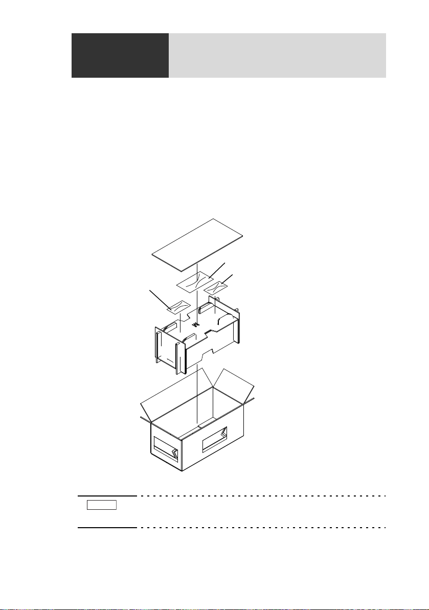
This chapter describes the necessary procedure from unpacking to
preparation before use.
1.1 Checking at unpacking
When you receive the product, check that all accessories are included
and that the accessories have not been damaged during transportation.
If any of the accessories are damaged or missing, contact your Kikusui agent /distributor.
Fig.1-1 Packing/Unpacking (example for 700W type)
• We recommend that all packing materials be saved, in case
the product needs to be transported at a later date.
PAS SERIES Setup 1-1
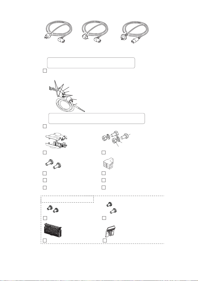
Plug:NEMA5-15
Rating:125 Vac/10A
[85-AA-0003]
Pulg: CEE7/7
Rating: 250 Vac/10A
[85-10-1070]
Pulg: GB1002
Rating: 250 Vac/10A
[85-10-0790]
or or
Power cord for the 350W/700W type (approx. 2.5 m)
The power cord that is provided varies depending on
the destination for the product at the factory-shipment.
Power cord for the 1000W type (with cable clamp, no plug and approx. 2.5 m)
Cable clamp: [P1-000-055] 1 pc.
Fastening plate: [D6-750-001] 1 pc.
Cable: [85-10-1010] 1 pc.
EMI core: [96-01-0180] 1 pc.
Accompanying screws B: [M3-112-017] 2 pcs.
Accompanying screws A: [M3-112-015] 2 pcs.
Accompanying nuts: [M8-500-003] 2 pcs.
For products with CE Marking (CE mark on the top cover),
an EMI core [96-01-0180] is embedded in the AC power cord.
M8 output terminal screws
2 sets
OUTPUT terminal cover
[M1-100-011]
[M5-101-007]
[M4-100-007]
1 set
[Q1-500-077]
M4 output terminal screws
2 pcs.
[M3-112-026]
TP-BUS connector
CD-ROM (1 pc.)
Safety information (1 pc.)
Setup Guide (1 pc.) Quick Reference
English 1 pc. , Japanese 1 pc.
M3 sensing terminal screws
M3 screws for chassis connection wire
2 pcs.
[M3-112-012]
1 pc. [M3-112-012]
1 pc. [M3-112-015]
These parts are installed in body.
J1protection socket
1 pc.
[84-49-0110]
J1 lock lever
1 pc.
[83-06-5060]
1 pc.
[84-61-5102]
Fig.1-2 Accessories
1-2Setup PAS SERIES

1.2 Precautions for installation
WARNING
NOTE
When installing this product, be sure to observe the precautions provided in the Safety information manual. Items specific to this product
are given below.
■ When installing this product, be sure to observe the
perature and humidity ranges indicated below.
tem
Operating temperature range: 0 °C to +50 °C (+32 °F to +122 °F)
h
Operating
■ When storing this product, be sure to observe the
perature and humidity ranges indicated below.
tem
Storage temperature range: -25 °C to +70 °C (-13 °F to +158 °F)
orage hu
St
umidity range: 20 % to 85 % RH
(no dew condensation is allowed)
midity range: 90 % RH or less
(no dew condensation is allowed)
1.3 Connecting the AC power cord
The AC power cord provided with the product varies depending on
the type.
For the connection procedure, see the respective section for each type.
350W and 700W types
Risk of electric shock.
• The PAS series conforms to IEC Safety Class I
(equipment that has a protective conductor terminal).
Be sure to earth ground the product to prevent electric shock.
• The PAS series is grounded through the power cord
roun
d wire. Connect the protective conductor termi-
g
nal to earth ground.
• Use the supplied power cord to connect to the AC line. If the supplied power cord cannot be used because the rated voltage or the
plug shape is incompatible, have a qualified engineer replace it with
an appropriate power cord that is 3 m or less in length. If obtaining a
power cord is difficult, contact your Kikusui agent or distributor.
PAS SERIES Setup 1-3

• Do not use the AC power cord provided with the product as a AC
power cord f
• The power cord with a plug can be used to disconnect the PAS
series from the AC po
an easily accessible power outlet so that the plug can be removed
from the outlet at any time.
• Secure adequate space around the po
power plug to an outlet where accessibility to the plug is poor. And,
do not place objects near the outlet that would result in poor accessibility to the plug.
or other instruments.
wer line in an emergency. Connect the plug to
wer plug
. Do not insert the
Connection procedure
1. Check that the supply voltage is within the line voltage
ra
nge of the power supply.
Input voltage range: 100 VAC to 240 VAC
Frequency range: 50 Hz to 60 Hz
2. Turn OFF the POWER switch.
3. Connect the AC power cord to the AC INPUT connector on
the rear panel.
Use the provided power code or power code that is selected by qualified
personnel.
4. Plug in the AC power cord.
1-4Setup PAS SERIES

1000W type
WARNING
CAUTION
NOTE
The AC power cord that is included with the 1000W type can be used
on either a 100-VAC or 200-VAC system.
Risk of electric shock.
• Before you connect the power cord, turn off the
switchboard breaker (a switch that cuts off the power
supply from the switchboard).
• The PAS series is an IEC Safety Class I equipment
quipme
(e
sure to ground the product to prevent electric shock.
• Connect the ground terminal to earth ground.
• Be sure to have a qualified engineer connect the
we
po
• The switchboard breaker must meet the requirements
sho
• Inside the power supply, an appropriate protective circuit is connected to the input terminal. Be sure to
connect th
and (GND) between the switchboard and the PAS
series.
nt with a protective conductor terminal). Be
r cable to the switchboard.
wn belo
w.
e wires correctly by matching the U, V, W,
• Use the supplied power cord to connect to the AC line.
• In an emergency, turn off the switchboard breaker to disconnect the
PAS series from the AC power line.
The PAS series is a piece of equipment that conforms to IEC Overvoltage Category II (equipment that consumes energy supplied from a
fixed installation).
■ Switchboard breaker requirements
• Rated current: 20 A (100 V system)/ 10 A (200 V system)
For safety, breakers whose rated current exceeds the specified current cannot be used.
• Only use the breaker with the PAS series.
• Keep the breaker readily accessible at all times.
fo
• Indicate that the breaker is dedicated
and that it is used to disconnect the product from the AC power line.
PAS SERIES Setup 1-5
r use with the PAS series
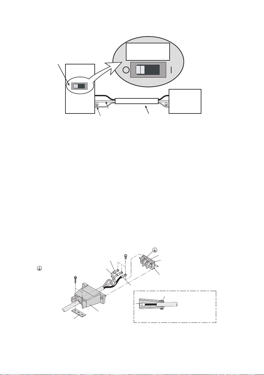
Fig.1-3 Connecting to the switchboard (Example: PAS10-105)
PAS10-105
N
L
N
Example:
PAS10-105
Switchboard
(whiteofblue)
L
(blackorbrown)
Examplecircuitbreakerlabel
ForPAS10-105
exclusiveuse
Suppliedpowercord
ForPAS10-105
exclusiveuse
(greenorgreen/yellow)
Cable clamper
N
L
(GND)
AC INPUT terminal board
N: White or blue
L: Black or brown
Fastening plate
Fastening plate
(GND): Green or green/yellow
Fix the covered part of the AC power
cord with the fastening plate.
Connection procedure
1. Chec
k that the supply voltage is within the line voltage
ra
nge of the power supply.
Input voltage range: 100 VAC to 240 VAC
Frequency range: 50 Hz to 60 Hz
2. Turn OFF the POWER switch.
3. Connect the provided AC power cord to the AC INPUT ter-
minal board as shown in Fig.1-4.
4. Attach crimp terminals to the AC power source side of the
AC power cord.
5. Turn OFF the switchboard.
6. Connect the AC power cord to match the L, N, and GND of
the switchboard.
1-6Setup PAS SERIES
Fig.1-4 Connection of the AC power cord on the unit side

Chapter. 2 Before Using the Unit
CAUTION
Before using the unit, users are requested to thoroughly understand
the following matters.
2.1 Inrush Current
An inrush current flows when the POWER switch is turned on. If you
are planning to use several sets of the unit in a system and turn on
their POWER switches simultaneously, check that the AC power
source or the switchboard is of sufficient capacity.
For details on the inrush current of each model, see Chapter8 "Specifications".
• Allow at least 10 seconds between power cycles.
Repeated on/off of the POWER switch at short intervals can cause malfunction of the inrush current limit-
circuit and shorten the service life of the input
ing
fuse and POWER switch.
2.2 Load
Note that the output will become unstable if the following types of
loads are connected.
1. When Load Current Has Peaks or Is Pulse-Shaped
2. When the Load Generates a Reverse Current to the Power Supply
3. When the Load Has Accumulated Energy Such as Batteries
2.2.1 When Load Current Has Peaks or Is Pulse-
Shaped
The current meter on the unit indicates only mean values. Even when
the indicated value is less than the preset current value, the peak values may actually exceed the preset current value. In such case, the
unit is instantaneously put into constant-current operation mode, and
the output voltage drops accordingly.
For these types of loads, you must increase the preset current value or
increase the current capacity.
PAS SERIES Before Using the Unit 2-1
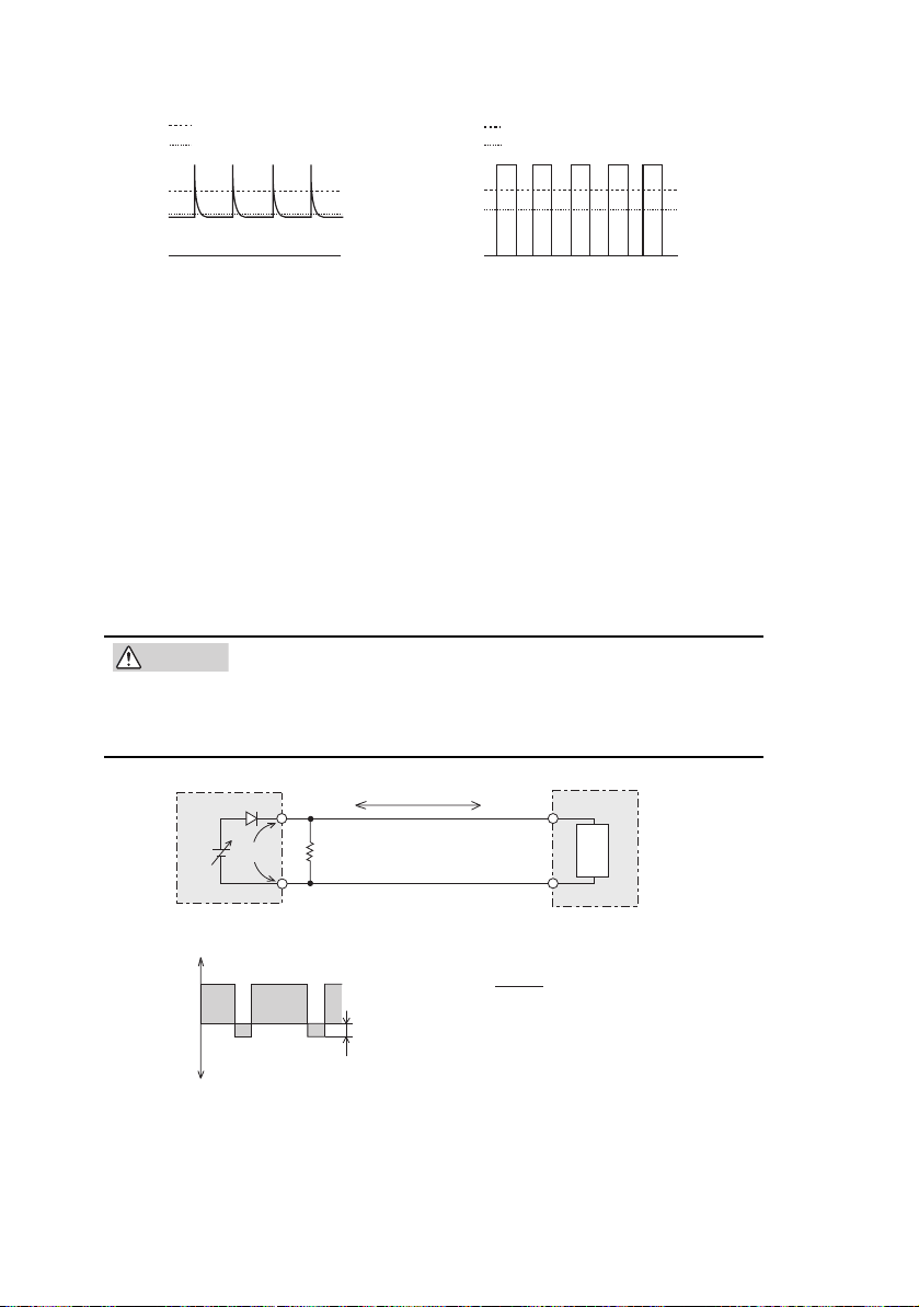
Fig.2-1 Load current with peaks
Preset constant current value
Meter indication value (mean value)
Preset constant current value
Meter indication value (mean value)
CAUTION
IO
RD
EO
Equivalent circuit of the unit
Regenerative load
Load
+
0
Reverse current
Output current
waveform
-I
O
+IO
Irp
RD[ȍ]
E
O
[V]
I
rp
[A]
RD: Reverse current bypass dummy load
E
O: Output voltage
I
rp: Max. reverse current
Fig.2-2 Pulse-shaped load cur-
rent
2.2.2 When the Load Generates a Reverse Current to the Power Supply
The unit cannot absorb a reverse current from a regenerative load
such as an inverter, converter, or transformer that supplies current to a
power supply. Consequently, the output voltage will increase and the
output will fluctuate.
For these types of loads, connect a resistor R
bypass the reverse current. However, the current capacity to the load
decreases by Irp.
• For resistor RD, select an appropriate resistor rated
for the power (allowing sufficient margin).
If a resistor with insufficient rated power for the circuit
is used, it may burn out.
D as shown in Fig.2-3 to
2-2 Before Using the Unit PAS SERIES
Fig.2-3 Remedy for regenerative load
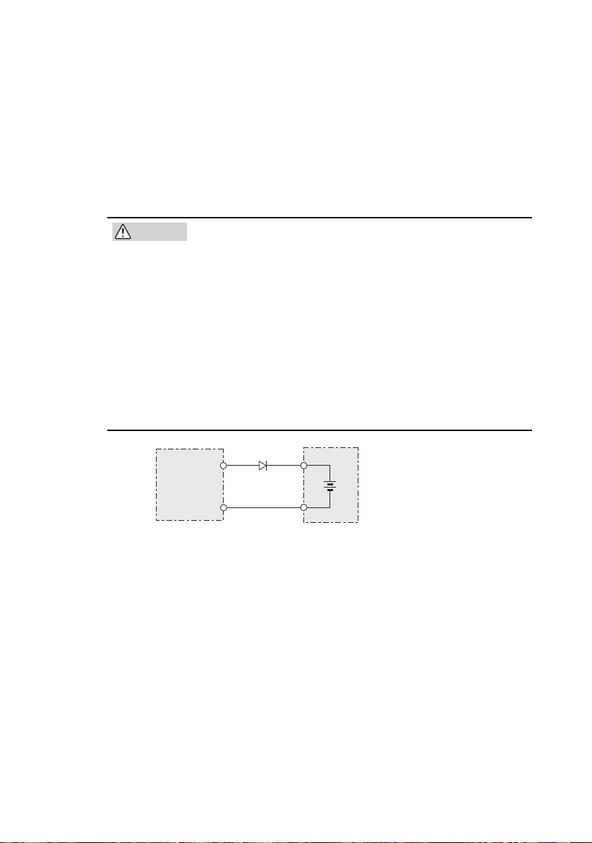
2.2.3 When the Load Has Accumulated Energy Such
CAUTION
Unit
Load with accumulated energy
DRP: Reverse-current-prevention diode
DRP
as Batteries
Connecting a load with accumulated energy, such as a battery, to the
unit may cause current to flow from the load to the internal circuit of
the unit. This current may damage the unit or reduce the life of the
load.
For this type of loads, connect a reverse-current-prevention diode
RP) between the unit and the load in series as shown in Fig.2-4.
(D
• To protect the load and the unit, select DRP according
to the following criteria.
1. Reverse voltage withstand capacity: At least twice
ed output voltage of the unit.
the rat
2. Forward current capacity: Three to ten times the
ate
d output current of the unit.
r
3. A diode with small loss.
• Be sure to take into account the heat generated by
RP. DRP may burn out with inadequate heat dissipa-
D
tion.
• Cannot be used in combination with remote sensing.
Fig.2-4 Remedy against load with accumulated energy
PAS SERIES Before Using the Unit 2-3

2.3 CV Power Supply and CC Power Supply
Output current Io Output current Io
0
0
Constant
Constant
Output voltage Eo
Output voltage Eo
Eo
Io
Io
Eo
This unit is capable of both constant voltage and constant current
operation. This section describes these operations.
An ideal constant voltage power supply has zero output impedance at
frequen
all
load current variations. An ideal constant current power supply has
infinite output impedance at all frequencies and maintains constant
current by absorbing the load resistance variations by changing the
voltage.
cies and maintains a constant voltage against all types of
Fig.2-5
Ideal constant voltage power
supply
However, the output impedance of an actual constant voltage or constant
current po
wer supply is neither zero nor infinite and has a frequency response. In addition, since the output has limitations in terms
of maximum voltage and maximum current, power supplies are
unable to maintain a constant voltage or current for all types of load
current variations and load resistance variations. The following
describes the relationship between the basic operations in constant
voltage (CV) and constant current (CC) modes and the limit setting of
the unit.
The following description assumes a power supply with a DC output
of 100 V and 10 A (maximum rated output voltage of 100 V and maximum rated output current of 10A) as an example.
A resistive load of 10 Ω is connected to the output terminals of the
power supply, and the output current limit is set to 5 A. In this condition, the output voltage is raised gradually from 0 V. At this point, the
power supply is operating in the constant voltage (CV) mode. The
2-4 Before Using the Unit PAS SERIES
Fig.2-6
Ideal constant current
power supply
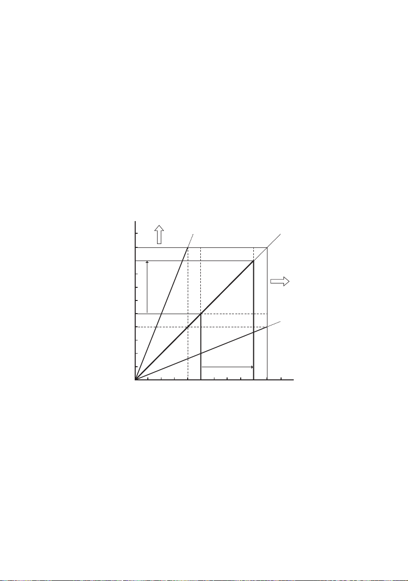
output current increases as the output voltage increases. When the
Load line of RL = 4 ȍ
Load line of RL = 10ȍ
Load line of RL = 25 ȍ
Area where current
capacity needs to be
increased
Area where voltage
needs to be increased
0 5 A 10 A9 A4 A
50 V
90 V
100 V
40 V
Output current Io
Output voltage Eo
output voltage reaches 50 V (that is, the output current has reached
5 A), the output voltage no longer increases even if you attempt to
raise it. This is because the output current is limited to 5 A specified
initially, causing the power supply to switch to the constant current
(CC) operation mode. In this way, the power supply automatically
switches from the constant voltage to constant current operation to
prevent an overcurrent from flowing. (The point at which the operation mode switches is called the "crossover point".) If the current
limit is raised in this condition, the power supply returns to the previous constant voltage operation, allowing you to increase the output
voltage further. If the current limit is increased from 5 A to 9 A in
Fig.2-7, a voltage of up to 90 V can be output.
Fig.2-7 Constant voltage operation and constant current
Next, let's assume the case in which a load resistance of 4 Ω is used.
The output current limit is considered to be the rated maximum output current. If you increase the output voltage from 0 V, the output
per
ion
at
o
current reaches the output current limit when the output voltage
reaches 40 V; the power supply cannot output a voltage above 40 V.
This is the limit even though the power supply is generating less than
half its output capacity in terms of power. If you wish to increase the
PAS SERIES Before Using the Unit 2-5

output voltage further, the unit needs to be replaced by a model having larger current capacity. Particularly for loads into which a transient peak current flows, the current must be set such that its peak
does not reach (or exceed) the current limit. If the unit enters constant
current operation mode even when the current is set to the rated output current, the current capacity needs to be raised.
Next, we consider a case in which a load resistance of 25 Ω is used. In
this case, if the output current limit is set to 4 A or more, the power
supply can output voltages from 0 V to the rated maximum output
voltage in the constant voltage operation mode. The output voltage
limit is set to the rated maximum output voltage under this load condition, and the output current is gradually increased from 0 A. At this
point, the power supply is operating in the constant current (CC)
mode. The output voltage increases as the output current increases.
When the output voltage reaches 100 V, the output current no longer
increases even if you attempt to raise it. If you wish to increase the
current flow further in this condition, the unit needs to be replaced by
a model having higher output voltage. Particularly for loads that generate transient surge voltage, the voltage must be set so that the surge
voltage does not reach (or exceed) the voltage limit.
2-6 Before Using the Unit PAS SERIES

2.4 Alarm
The unit is equipped with the following protection function. When
the protection function is activated, "ALM" on the front panel display
lights, and the OUTPUT is turned off or the POWER switch is shut
down. However, the only action available when OHP is activated is
turning off the OUTPUT. (See Fig.2-8.)
In addition, an ALARM signal is output to pin 20 of the J1 connector
when the protection function is activated. (See Fig.2-9.)
For details on selecting whether to turn off the OUTPUT or shut
down the POWER switch when an alarm is activated, see "3.2.4 Unit
Configuration (CONFIG)".
When POWER switch shutdown is selected, the illumination of
"ALM" and the ALARM signal output is held for approximately 0.5 s.
Recovery from an alarm
• When POWER switch shut down is selected
After clearing the abnormal condition that
on the PO
• When OUTPUT OFF is selected
Turn off the POWER switch, clear the abnormal condition that
caused the alarm,
WER switch.
and turn on the POWER switch.
caused the alarm, turn
■ Prot
PAS SERIES Before Using the Unit 2-7
ection Function
VP (overvoltage protection)
• O
The overvoltage protection function protects a load from unexpect-
high vo
edly
a preset voltage (OVP trip point).
Selectable range: 10 % to 110 % of the rated output voltage.
If the OVP function is activated when CONFIG is set to OUTPUT
OFF, the voltage display shows "OVP."
For details, see "3.2.2 Setting the OVP (Overvoltage Protection) Trip
Point".
ltage. The function is activated when the voltage exceeds

• OCP (overcurrent protection)
CV
OUTPUT
OFF ALM
V/
W
A/
W
CC
ON
The overcurrent protection function protects a load from unexpectedly high current. The function is
activated when the current exceeds
a preset current (OCP trip point).
Selectable range: 10 % to 110 % of the rated output current.
If the OCP function is activated when CONFIG is set to OUTPUT
OFF, the voltage display shows "OCP."
For details, see "3.2.3 Setting the OCP (Overcurrent Protection) Trip
Point".
• OHP (Overheat Protection)
This function is activated when the
es abnormally.
rais
internal temperature of the unit
This function protects the unit from the following conditions.
• When the unit is used in an environment exceeding the operation temperature range
• When the unit is used with the inlet or exhaust port blocked
• When the fan motor stops
ltage display shows "OHP".
If the OHP function is activated, the
vo
If the condition that caused the OHP to be activated is not corrected,
the OHP function is activated again when the POWER switch is
turned on.
Fig.2-8 ALARM indication example (OHP)
2-8 Before Using the Unit PAS SERIES
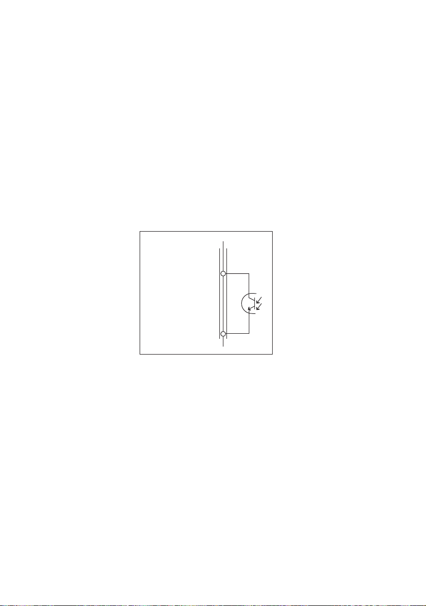
• SHUT (Shutdown)
20
17
J1 connector
ALARM STATUS
ALARM COMMON
Inside
the unit
The OUTPUT or the POWER switch can be turned OFF by applying
a shutdown
signal to the J1 connector on the rear panel. If the shutdown signal is applied when CONFIG is set to OUTPUT OFF, the
voltage display shows "SHUT."
For details, see "4.1.7 Controlling the Output Shutdown Using External Contact".
■ Alar
m Signal
Since the alarm signal output uses an open-col
is isolated from other terminals.
Maximum voltage: 30 V
Maximum current: 8 mA
Fig.2-9 ALARM signal
lector photocoupler, it
PAS SERIES Before Using the Unit 2-9

2.5 Grounding the Output Terminal
WARNING
• For safety reasons, even if the output terminal is
grounded, make sure the insulation capacity of the
output terminal (including the sensing terminal) is
greater than the isolation voltage of the unit.
If you cannot obtain a cable with sufficient rated voltage, secure adequate withstand voltage such as by
assing t
p
withstand voltage greater than the isolation voltage of
the unit.
If adequate insulation measures are not taken
ga
a
may occur when grounding is poor.
• If the unit is to be remotely controlled through an
xt
e
output (leave it floating). If the Vext output is
grounded in the example shown in Fig.2-11, the output is short-circuited (which can cause accidents).
The output terminal of the unit is isolated from the protective grounding terminal. By connecting the GND wire of the AC power cord to
the ground termi
ground potential (see Fig.2-10).
Consequently, the cable and load that are connected to
mi
nal (including the sensing terminal) must have an insulation capacity that is greater than the isolation voltage of the unit with respect to
the chassis.
In addition, pins 3 through 9 of the J1 connector on the rear panel (for
analog remote control and output monitoring) are at approximately
the same potential as the - (neg.) output terminal of the unit. Therefore, cables and devices that are connected to these pins must also
have an insulation capacity that is greater than the isolation voltage of
the unit.
he cable through an insulation tube with a
inst the isolation voltage of the unit, electric shock
ernal voltage source (Vext), do not ground the Vext
nal of the switchboard, the chassis of the unit is set to
the output ter-
2-10 Before Using the Unit PAS SERIES
 Loading...