

Kikusui PAN 160-1A, PAN 110-1.5A, PAN 60-3A, PAN 70-2.5A, PAN 16-18A Operation Manual
...
Part No. Z1-002-322, IA003474
OPERATION MANUAL
Regulated DC Power Supply
PAN-A Series
175W MODEL
PAN 16-10A
PAN 60-3A
PAN 110-1.5A
350W MODEL
PAN 16-18A
PAN 60-6A
PAN 110-3A
700W MODEL
PAN 16-30A
PAN 60-10A
PAN 110-5A
PAN 250-2.5A
1000W MODEL
PAN 16-50A
PAN 60-20A
PAN 110-10A
PAN 250-4.5A
PAN 600-2A
PAN 35-5A
PAN 70-2.5A
PAN 160-1A
PAN 35-10A
PAN 70-5A
PAN 160-2A
PAN 35-20A
PAN 70-8A
PAN 160-3.5A
PAN 35-30A
PAN 70-15A
PAN 160-7A
PAN 350-3.5A
Apr. 2009

About This Manual
If you find any incorrectly arranged or missing pages in this manual, they will be
replaced. If the manual gets lost or soiled, a new copy can be provided for a fee. In
either case, please contact Kikusui agent/distributor, and provide the "Part No." given
on cover.
This manual has been prepared with the utmost care; however, if you have any questions, or note any errors or omissions, please contact Kikusui agent/distributor.
All or any parts of this manual may not be reproduced in any forms, without express
written permission of Kikusui Electronics Corporation.
The contents of this manual are subject to change without notice.
© 2004-2009 Copyright Kikusui Electronics Corporation.
All rights reserved.

Power Requirements of this Product
Power requirements of this product have been changed and the
relevant sections of the Operation Manual should be revised
accordingly. (Revision should be applied to items indicated by a
check mark .)
Input voltage
The input voltage of this product is _______________ VAC,
and the voltage range is __________ to
Use the product within this range only.
Input fuse
The rating of this product's input fuse is
___________ A, ___________ .___________ VAC, and
WARNING
3
To avoid electrical shock, always disconnect the
•
AC power cord or turn off the switch on the
switchboard before attempting to check or replace
the fuse.
•
Use a fuse element having a shape, rating, and
characteristics suitable for this product. The use of
a fuse with a different rating or one that short
circuits the fuse holder may result in fire, electric
shock, or irreparable damage.
______________ VAC.
PAN-A
I

II PAN-A
Safety Symbols
For the safe use and safe maintenance of this product, the
following symbols are used throughout this manual and on
the product. Understand the meanings of the symbols and
observe the instructions they indicate (the choice of symbols used depends on the products).
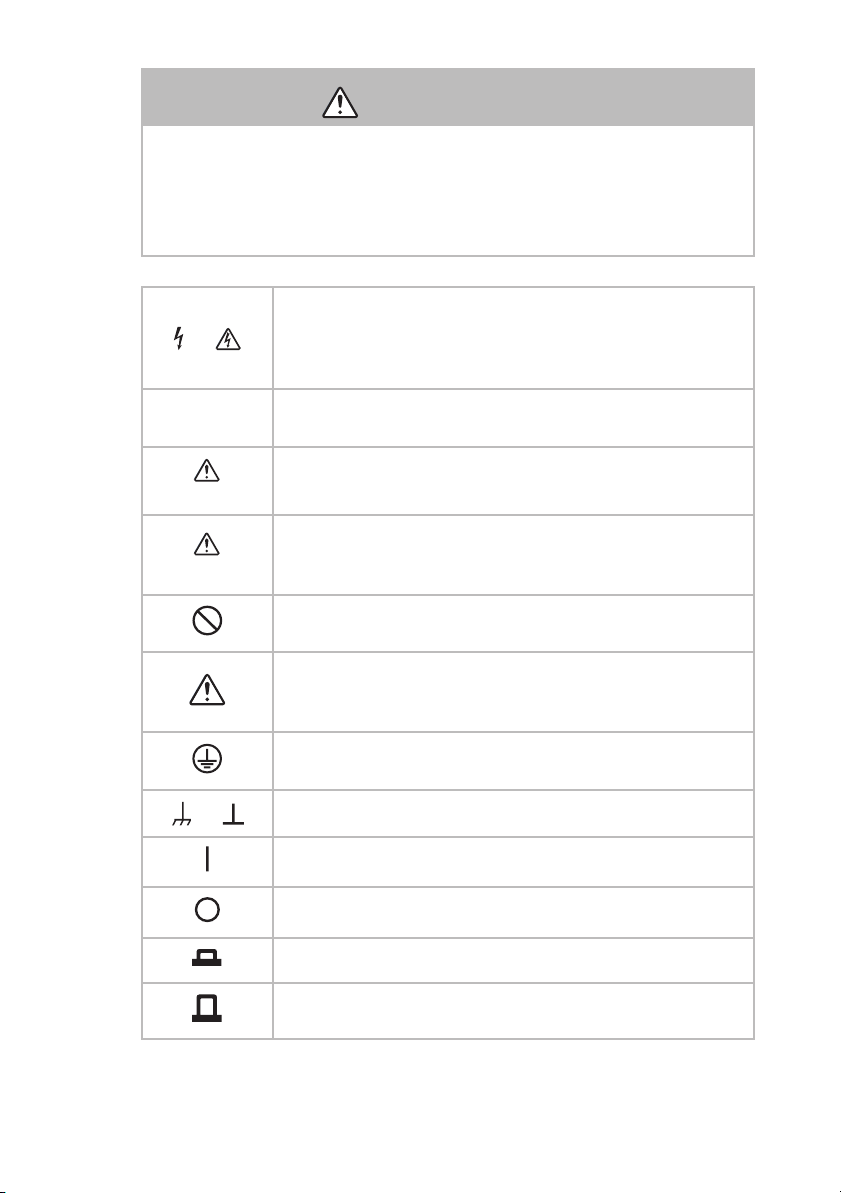
Indicates that a high voltage (over 1000 V) is used here.
or
Touching the part causes a possibly fatal electric shock. If
physical contact is required by your work, start work only
after you make sure that no voltage is output here.
DANGER
WARNING
CAUTION
or
Indicates an imminently hazardous situation which, if
ignored, will result in death or serious injury.
Indicates a potentially hazardous situation which, if
ignored, could result in death or serious injury.
Indicates a potentially hazardous situation which, if
ignored, may result in damage to the product and other
property.
Shows that the act indicated is prohibited.
Indicates a general danger, warning, or caution.
When this symbol is marked on the product, see the relevant sections in this manual.
Protective conductor terminal.
Chassis (frame) terminal.
On (supply)
Off (supply)
In position of a bi-stable push control
Out position of a bi-stable push control
PAN-A III
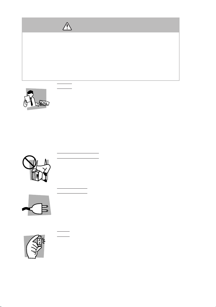
Safety Precautions
The following safety precautions must be observed to avoid
fire hazard, electrical shock, accidents, and other failures.
Keep them in mind and make sure that all of them are
observed properly.
Using the product in a manner that is not specified in this
manual may impair the protection functions provided by the
product.
Users
Operation
Manual
• This product must be used only by qualified
personnel who understand the contents of this
operation manual.
• If it is handled by disqualified personnel, personal
injury may result. Be sure to handle it under
supervision of qualified personnel (those who
have electrical knowledge.)
• This product is not designed or produced for
home-use or use by general consumers.
Purposes of use
• Do not use the product for purposes other than
those described in the operation manual.
Line
Voltage
Input power
• Use the product with the specified input power
voltage.
• For applying power, use the AC power cord
provided. For details, see the relevant page of this
operation manual.
Fuse
• With products with a fuse holder on the exterior
surface, the fuse can be replaced with a new one.
When replacing a fuse, use the one which has
appropriate shape, ratings, and specifications.
IV PAN-A
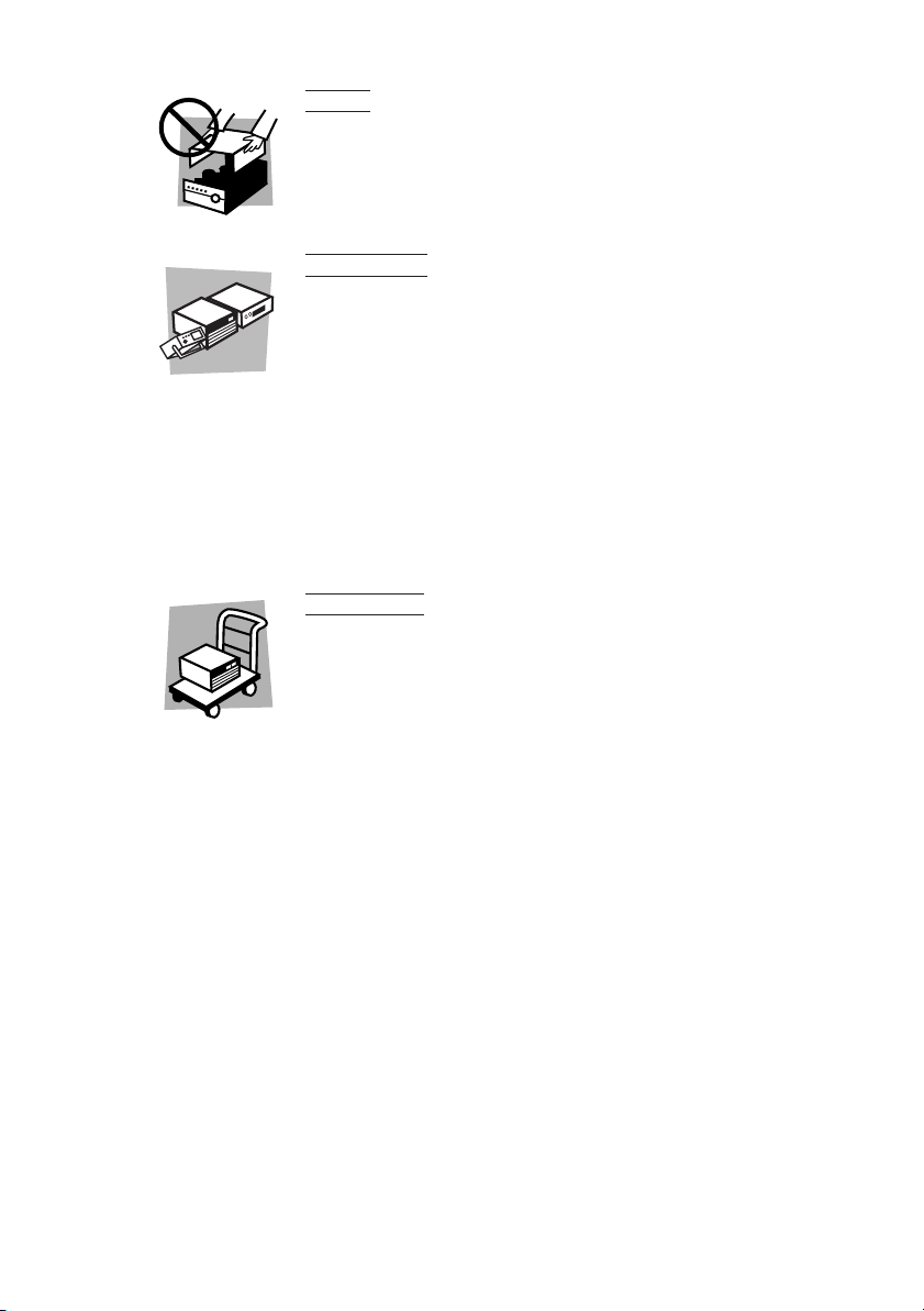
Cover
• There are parts inside the product which may
cause physical hazards. Do not remove the
external cover.
Installation
• When installing products be sure to observe "1.3
Precautions for installation" described in this
manual.
• To avoid electrical shock, connect the protective
ground terminal to electrical ground (safety
ground).
• When applying power to the products from a
switchboard, be sure work is performed by a
qualified and licensed electrician or is conducted
under the direction of such a person.
Relocation
• Turn off the power switch and then disconnect all
cables when relocating the product.
• Use two or more persons when relocating the
product which weights more than 20 kg. The
weight of the products can be found on the rear
panel of the product and/or in this operation
manual.
• Use extra precautions such as using more people
when relocating into or out of present locations
including inclines or steps. Also handle carefully
when relocating tall products as they can fall over
easily.
• Be sure the operation manual be included when
the product is relocated.
PAN-A V
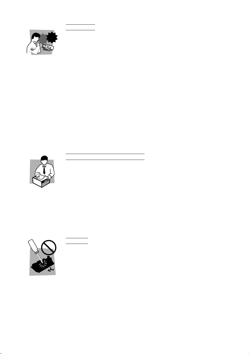
Check?
Operation
• Check that the AC input voltage setting and the
fuse rating are satisfied and that there is no
abnormality on the surface of the power cord. Be
sure to unplug the power cord or stop applying
power before checking.
• If any abnormality or failure is detected in the
products, stop using it immediately. Unplug the
power cord or disconnect the power cord from the
switchboard. Be careful not to allow the product to
be used before it is completely repaired.
• For output wiring or load cables, use connection
cables with larger current capacity.
• Do not disassemble or modify the product. If it
must be modified, contact Kikusui distributor/
agent.
Maintenance and checking
• To avoid electrical shock, be absolutely sure to
unplug the power cord or stop applying power
before performing maintenance or checking.
• Do not remove the cover when performing
maintenance or checking.
• To maintain performance and safe operation of
the product, it is recommended that periodic
maintenance, checking, cleaning, and calibration
be performed.
Service
• Internal service is to be done by Kikusui service
engineers. If the product must be adjusted or
repaired, contact Kikusui distributor/agent.
VI PAN-A

Arrangement of this manual
This Operation Manual is made up of the following sections.
Preface
Describes all the models covered by this manual, as well as outlines the features of each model.
Chapter 1 "Setup"
This chapter describes the necessary procedure from unpacking
to preparation before use. Since details on installation location
and power supply are provided, be sure to read this chapter
before using the unit for the first time.
Chapter 2 "Before Using the Unit"
Before using the power supply, users are requested to thoroughly
understand the following units.
Chapter 3 "Basic Operation"
Describes the unit’s start-up function, protection circuit, and the
basic operations managed from the front panel of the unit.
Chapter 4 "Applied Operation"
Explains the remote control of the unit, and use of multiple number of power supply in combination to increase output capacity.
Chapter 5 "Names and Functions of Controls"
Provides an outline of the switches and terminals on the panels,
including their names and functions.
Read this chapter to learn the meanings of the caution
marks indicated on the panels of the unit.
Chapter 6 "Maintenance"
Describes the daily inspection procedures and the adjustment
conducted when necessary. To remote-control the unit, such
adjustment is necessary. Follow the adjustment procedures
detailed in this chapter. The chapter also describes some symptoms of possible problems encountered during use of the unit,
along with appropriate remedies.
PAN-A VII

Chapter 7 "Specifications"
Describes the electrical, mechanical and general specifications of
the unit.
VIII PAN-A

CONTENTS
Safety Symbols- - - - - - - - - - - - - - - - - - - - - - - - - - - - - - - - - - - - - III
Safety Precautions - - - - - - - - - - - - - - - - - - - - - - - - - - - - - - - - - - IV
Arrangement of this manual - - - - - - - - - - - - - - - - - - - - - - - - - - VII
Preface - - - - - - - - - - - - - - - - - - - - - - - - - - - - - - - - - - - - - - - - - P-1
Outline of the manual - - - - - - - - - - - - - - - - - - - - - - - - - - - - - - - - - - - - - P-1
Introduction of the products - - - - - - - - - - - - - - - - - - - - - - - - - - - - - - - - - P-2
Option- - - - - - - - - - - - - - - - - - - - - - - - - - - - - - - - - - - - - - - - - - - - - - - - P-3
Chapter 1 Setup- - - - - - - - - - - - - - - - - - - - - - - - - - - - - - - - - - - 1-1
1.1 Checks during unpacking - - - - - - - - - - - - - - - - - - - - - - - - - - - - - - 1-1
1.2 Precautions for moving - - - - - - - - - - - - - - - - - - - - - - - - - - - - - - - - 1-5
1.3 Precautions for installation - - - - - - - - - - - - - - - - - - - - - - - - - - - - - 1-8
1.4 Checking the input fuse- - - - - - - - - - - - - - - - - - - - - - - - - - - - - - - - 1-9
1.5 Connecting the AC power code - - - - - - - - - - - - - - - - - - - - - - - - - 1-10
1.6 Grounding- - - - - - - - - - - - - - - - - - - - - - - - - - - - - - - - - - - - - - - - 1-14
Chapter 2 Before Using the Unit - - - - - - - - - - - - - - - - - - - - - - - 2-1
2.1 Inrush current - - - - - - - - - - - - - - - - - - - - - - - - - - - - - - - - - - - - - - 2-1
2.2 Negative voltage - - - - - - - - - - - - - - - - - - - - - - - - - - - - - - - - - - - - 2-1
2.3 Output terminals on the front panel - - - - - - - - - - - - - - - - - - - - - - - - 2-2
2.4 Load - - - - - - - - - - - - - - - - - - - - - - - - - - - - - - - - - - - - - - - - - - - - 2-2
2.4.1 When load current has peaks or is pulse-shaped- - - - - - - - - - - - 2-2
2.4.2 When a load generates a reverse current to the power supply - - - 2-3
2.4.3 In case of load with accumulated energy, such as batteries - - - - 2-4
2.5 CV power supply and CC power supply- - - - - - - - - - - - - - - - - - - - - 2-5
2.6 Output Terminal Isolation - - - - - - - - - - - - - - - - - - - - - - - - - - - - - - 2-8
Chapter 3 Basic Operation - - - - - - - - - - - - - - - - - - - - - - - - - - - 3-1
3.1 Turning on the power - - - - - - - - - - - - - - - - - - - - - - - - - - - - - - - - - 3-1
3.2 Basic operation - - - - - - - - - - - - - - - - - - - - - - - - - - - - - - - - - - - - - 3-4
3.2.1 OVP(Over Voltage Protection) trip point presetting - - - - - - - - - 3-4
3.2.2 Using as a constant voltage power supply- - - - - - - - - - - - - - - - 3-6
3.2.3 Using as a constant current power supply - - - - - - - - - - - - - - - - 3-7
3.3 Connecting load- - - - - - - - - - - - - - - - - - - - - - - - - - - - - - - - - - - - - 3-8
3.4 Mounting the auxiliary output terminal cover - - - - - - - - - - - - - - - - 3-13
3.5 Fixing output presetting - - - - - - - - - - - - - - - - - - - - - - - - - - - - - - 3-14
PAN-A IX

Chapter 4 Applied Operation - - - - - - - - - - - - - - - - - - - - - - - - - 4-1
4.1 CONTROL terminal board - - - - - - - - - - - - - - - - - - - - - - - - - - - - - - 4-1
4.2 Remote sensing - - - - - - - - - - - - - - - - - - - - - - - - - - - - - - - - - - - - -4-5
4.3 Analog remote control - - - - - - - - - - - - - - - - - - - - - - - - - - - - - - - -4-10
4.3.1 Controlling output voltage with external resistor - - - - - - - - - - 4-12
4.3.2 Controlling output voltage with external voltage - - - - - - - - - - 4-14
4.3.3 Controlling output current with external resistor- - - - - - - - - - - 4-18
4.3.4 Controlling output current with external voltage- - - - - - - - - - - 4-20
4.3.5 Output ON/OFF control - - - - - - - - - - - - - - - - - - - - - - - - - - - 4-24
4.4 Master-slave-control parallel operation- - - - - - - - - - - - - - - - - - - - - 4-26
4.5 Master-slave-control series operation - - - - - - - - - - - - - - - - - - - - - -4-35
Chapter 5 Names and Functions of Controls - - - - - - - - - - - - - - 5-1
5.1 Front panel- - - - - - - - - - - - - - - - - - - - - - - - - - - - - - - - - - - - - - - - -5-1
5.2 Rear panel - - - - - - - - - - - - - - - - - - - - - - - - - - - - - - - - - - - - - - - - -5-7
Chapter 6 Maintenance - - - - - - - - - - - - - - - - - - - - - - - - - - - - - 6-1
6.1 Cleaning - - - - - - - - - - - - - - - - - - - - - - - - - - - - - - - - - - - - - - - - - -6-1
6.2 Inspection - - - - - - - - - - - - - - - - - - - - - - - - - - - - - - - - - - - - - - - - - 6-1
6.3 Adjustment - - - - - - - - - - - - - - - - - - - - - - - - - - - - - - - - - - - - - - - -6-2
6.3.1 Test equipment required - - - - - - - - - - - - - - - - - - - - - - - - - - - -6-2
6.3.2 Adjustment procedure - - - - - - - - - - - - - - - - - - - - - - - - - - - - -6-2
6.4 Malfunctions and Causes - - - - - - - - - - - - - - - - - - - - - - - - - - - - - - -6-9
Chapter 7 Specifications - - - - - - - - - - - - - - - - - - - - - - - - - - - - 7-1
Common Specifications - - - - - - - - - - - - - - - - - - - - - - - - - - - - - - - - - - - -7-1
Specifications of PAN-A Series Model 175W - - - - - - - - - - - - - - - - - - - - -7-2
Specifications of PAN-A Series Model 350W - - - - - - - - - - - - - - - - - - - - -7-8
Specifications of PAN-A Series Model 700W - - - - - - - - - - - - - - - - - - - -7-14
Specifications of PAN-A Series Model 1000W - - - - - - - - - - - - - - - - - - - 7-20
INDEX- - - - - - - - - - - - - - - - - - - - - - - - - - - - - - - - - - - - - - - - - - - I-1
X PAN-A
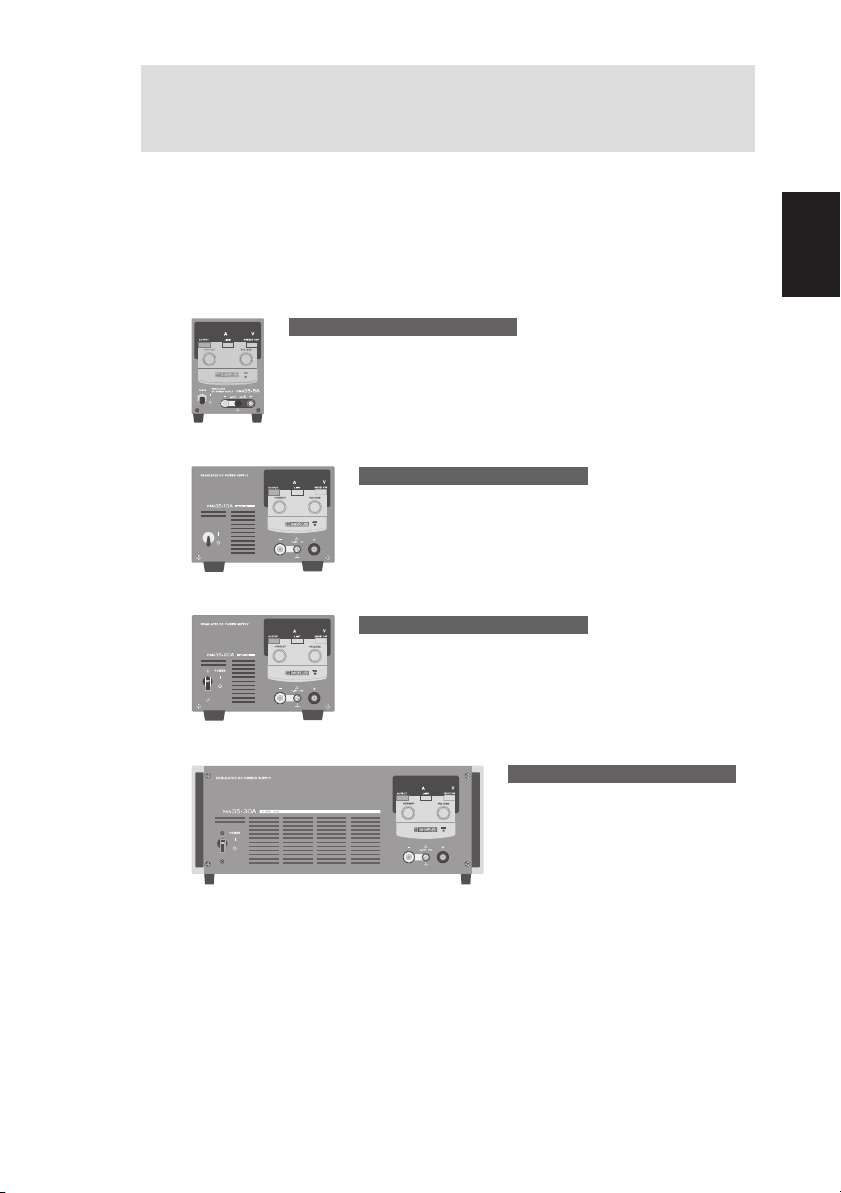
Preface
Outline of the manual
The PAN-A series is classified depending on output capacity. This
Operation Manual describes the PAN-A series, including the specific
types named below.
PAN-A SERIES MODEL 175W
PAN16-10A, PAN35-5A,
PAN60-3A, PAN70-2.5A,
PAN110-1.5A, PAN160-1A
PAN-A SERIES MODEL 350W
1
POWER
1
PAN16-18A, PAN35-10A,
PAN60-6A, PAN70-5A,
PAN110-3A, PAN160-2A
PAN-A SERIES MODEL 700W
PAN16-30A, PAN35-20A,
PAN60-10A, PAN70-8A,
PAN110-5A, PAN160-3.5A,
PAN250-2.5A
Preface
PAN-A SERIES MODEL 1000W
PAN16-50A, PAN35-30A,
PAN60-20A, PAN70-15A,
PAN110-10A, PAN160-7A,
PAN250-4.5A,PAN350-3.5A
PAN600-2A
Fig.P-1 Models and types covered by this manual
PAN-A P-1

Introduction of the products
The PAN-A series is an automatic constant voltage/constant current
shifting regulated DC power supply equipped with the phase control
pre-regulator. A series regulator system is used to assure low-noise
and stable output.
The PAN-A series are featured with the following points.
• The two distinctly visible LED display units on the front panel display output voltage, output current and various preset data.
• The output control potentiometer (for voltage and current presetting) is of a 10-turns wire-wound design, and allows precise setting.
• For both the front and rear panels, the output terminals can be
equipped with a cover for safety.
• Using external voltage or external resistor, output voltage and current can be remote-controlled.
For remote-control operations using an external voltage, you can
also perform adjustments output using the knob on the front panel.
• The remote control and remote sensing terminals use screwless terminal boards, which facilitates wiring.
• Using the Kikusui power supply controller with the control board
allows you to construct an automatic tester and other systems.
• The PAN-A series uses a choke input smoothing circuit in the phase
control pre-regulator; input apparent power is less than for capacitor input smoothing circuits, improving the power factor at low outputs.
• High-speed transient response of 50μs allows it to follow a sudden
load change.
• Carefully selected parts, improved circuit, and forced air cooling
heat dissipation combine to produce an excellent low temperature
drift of 100 ppm/˚C (TYP value).
P-2 PAN-A
• To protect a load from unexpectedly excessive voltage, the unit
includes a built-in OVP (over-voltage protection) circuit capable of
handling voltages 10 % - 110 % of the rated output voltage.
The OVP (over-voltage protection) circuit has a preset feature,
allowing you to check the OVP set voltage even when the unit is
being used.
With the above-mentioned features, PAN-A series units offers a wide
range of applications to laboratory experimental equipment, test
equipment for mass-production lines, power supply for aging, etc.
Preface
NOTE
• Since this unit uses a phase control circuit for the pre-regulator, output is superimposed with pulsive noise. Although the
noise level is kept a few tens of mV, it may still cause some
problem with certain types of applications. Please study this
issue carefully before choosing which unit to use.
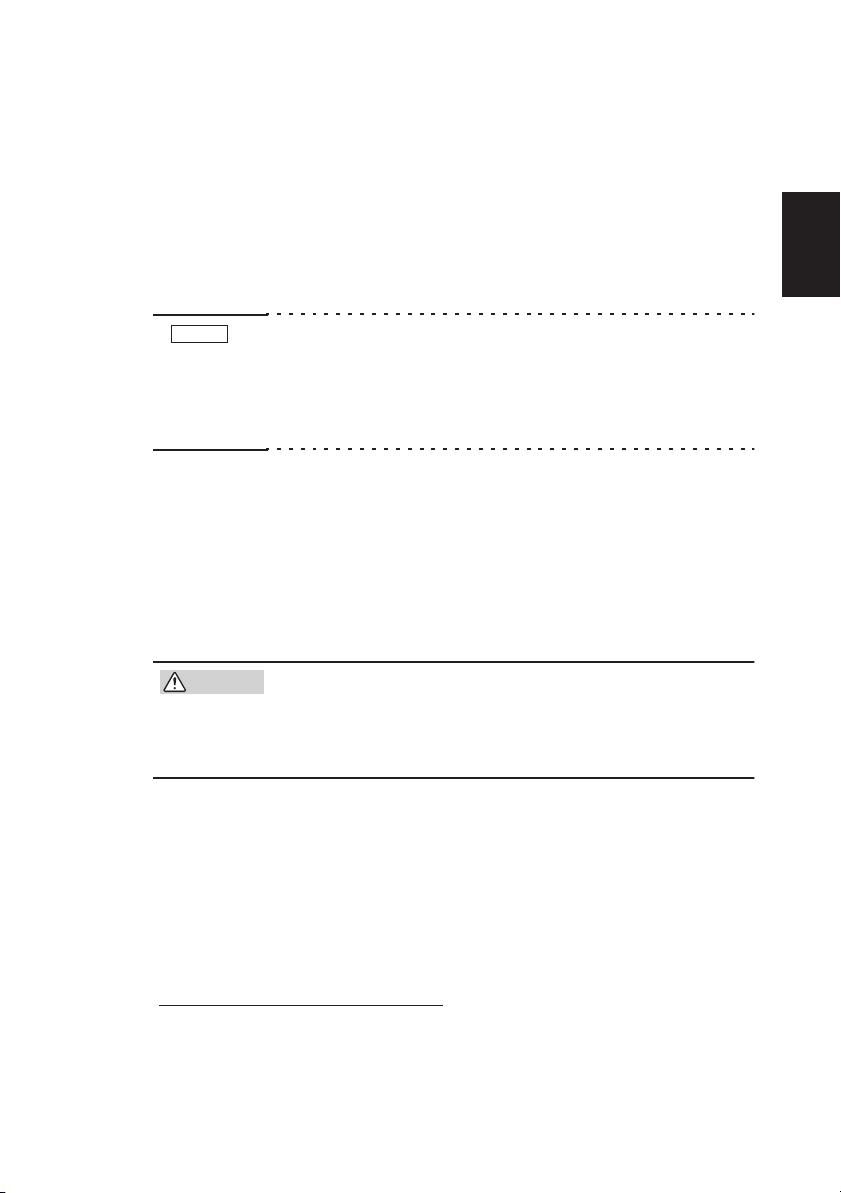
Option
The following optional accessories are available for rack mounting.
• Rack mount frame RMF4M (Metric rack conforming to JIS standards)
RMF4 (Inch rack conforming to EIA standards)
• Blank panel BP2, BP4
• Bracket B22, B42, BH4M, BH4
•
CAUTION
For details on optional accessories, contact your Kikusui agent.
The unit is furnished with air intake ports for forced air
cooling. For rack mounts, therefore, we request that
you mount a blank panel of at least one panel wide
on the rack.
*1
*1. One panel wide; JIS standard: 50 mm, EIA standard: 44.45
mm
PAN-A P-3
MODEL 175W
177 (6.67)
102 (4.02)
37.5
(1.48)
Blank panel BP2
Blank panel BP4
50505024.5
199
Rack mount frame
RMF4
465 (18.3)
482 (19.0)
Bracket B42
Unit: mm (inch)
Rack mount frame
RMF4M
Blank panel BP2
Blank panel BP4
465
480
Bracket B42
Unit: mm
Fig.P-2 Model 175W mounted into RMF4M/RMF4
P-4 PAN-A
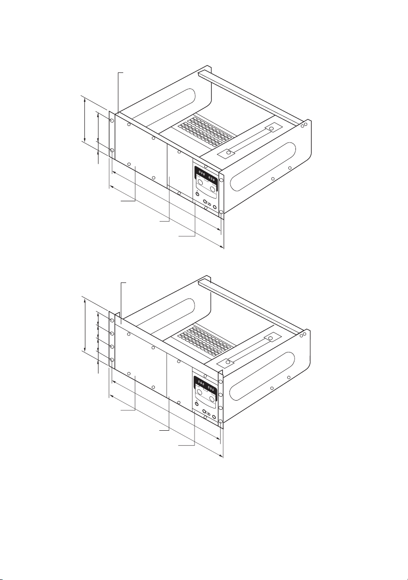
MODEL 350W/700W
Rack mount frame
RMF4
177 (6.67)
102 (4.02)
37.5
(1.48)
Blank panel BP2
50505024.5
199
Blank panel BP2
465 (18.3)
482 (19.0)
Bracket B22
Rack mount frame
RMF4M
465
480
Preface
Unit: mm (inch)
Bracket B22
Unit: mm
Fig.P-3 Model 350W/700W mounted into RMF4M/
RMF4
PAN-A P-5

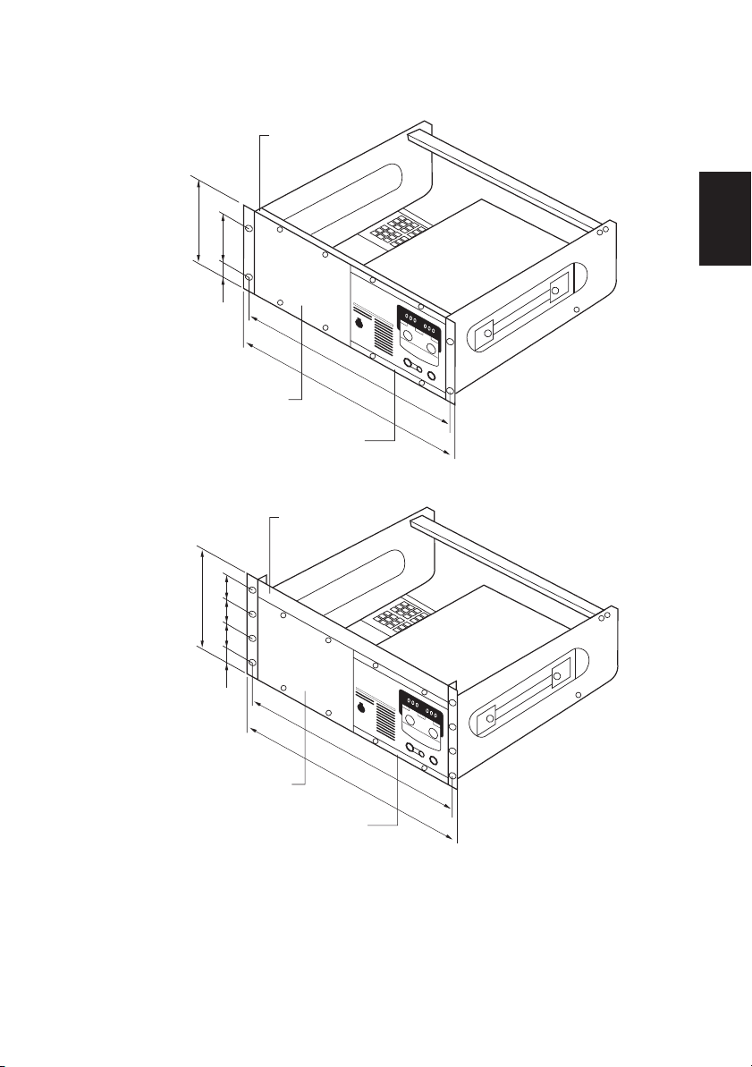
MODEL 1000W
160 (6.30)
102 (4.02)
21.5
(0.85)
462 (18.2)
482 (19.0)
Bracket BH4
Unit: mm (inch)
505050
199
24.5
460
480
Bracket BH4M
Unit: mm
Fig.P-4 Model 1000W with BH4M/ BH4 mounted on it
P-6 PAN-A
Chapter 1 Setup
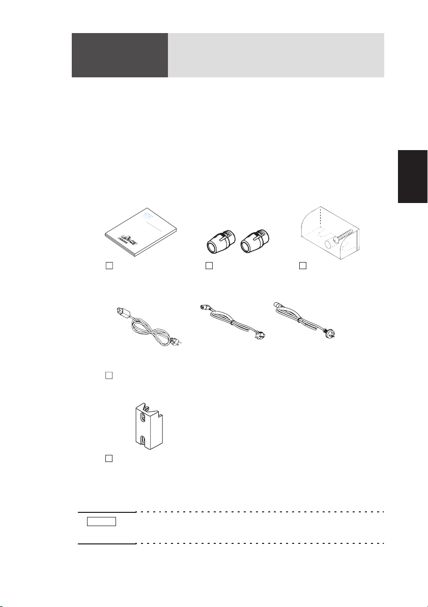
1.1 Checks during unpacking
When you unpack the product, make sure that you have all the parts
and that none have been damaged during transportation. If any parts
is damaged or missing, contact your Kikusui agent/distributor.
Accessories vary depending on the model.
MODEL 175W
P
A
1
7
5
P
W
A
M
P
N
A
P
1
N
A
6
3
6
-
N
5
0
0
W
P
1
3
1
A
M
A
P
0
N
O
A
-
D
1
P
1
N
E
.5
A
6
L
7
6
A
-
N
0
1
0
0
8
W
P
1
6
A
1
A
M
A
P
0
N
O
-
A
D
3
P
1
N
E
A
A
6
L
P
6
-
N
3
A
0
0
1
1
-
N
1
A
0
1
0
0
0
2
0
P
P
A
W
-
5
A
5
0
P
MO
A
P
N
-
A
2
A
P
1
D
N
.
N
5
A
E
6
A
P
L
6
-
N
P
5
A
0
A
0
P
1
-
N
P
2
N
A
A
1
A
0
0
2
N
P
3
N
A
-
5
A
1
5
6
0
7
0
-
N
0
2
0
A
4
0
1
-
.
5
8
6
2
A
A
0
A
P
-
A
3
P
N
.
5
A
A
P
3
N
A
5
P
7
-
N
3
A
0
0
1
-
N
1
A
6
5
3
0
A
5
7
0
A
3
.
5
A
Operation manual
[Z1-002-322]
Plug: NEMA5-15
[85-AA-0006]
AC power cable
Rear output terminal cover
(Mount on the unit. )
[Q5-000-160]
Chap.1
O
PE
R
e
R
P
g
a
rt
u
A
N
N
l
o
a
T
.
-
Z
t
A
e
IO
1
0
d
O
0
S
2
D
N
D
-3
e
E
2
L
r
C
2
MA
i
,
e
1
I
P
J
A
0
s
u
003
A
l
o
.
3
2
w
6
N
0
1
e
0
UA
4
r
S
u
P
L
p
A
p
P
N
A
l
y
P
3
N
A
5
7
-
N
5
0
A
P
1
2
A
6
.
0
5
N
A
A
1
3
N
A
5
7
1
0
0
1
5
A
6
A
0
2
A
0
A
Guard cap 2 pcs.
GP01-PMC
[83130]
Auxiliary output
terminal cover
Cover:[P1-000-048]
1
Setup
Screw:[M3-112-019]
or
Plug: CEE7/7
[85-AA-0005]
The power cord that is provided varies
depending on the destination for the product
at the factory-shipment.
or
Plug: CB1002
[85-10-0790]
Fig.1-1 Accessories (model 175W)
NOTE
• We recommend that all packing materials be saved, in case
the product needs to be transported at a later date.
PAN-A 1-1
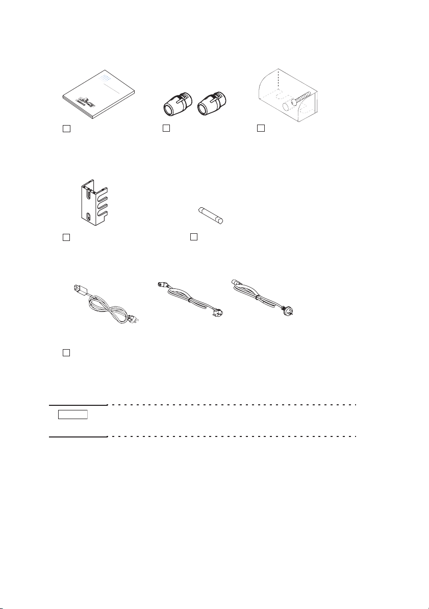
MODEL 350W
O
PE
R
e
R
P
gu
A
AT
1
N
l
7
at
5
P
W
A
ed
IO
A
M
P
N
O
S
A
D
N
P
D
1
e
N
E
A
6
L
r
C
3
M
6
i
-
N
5
e
1
P
0
0
0
W
s
P
1
3
A
A
1
A
o
M
A
P
0
N
w
O
N
A
-
D
1
P
e
1
N
E
.5
U
A
6
L
r
7
S
A
6
-
N
0
1
A
0
0
8
W
P
1
u
6
P
A
L
1
A
p
M
A
A
P
0
N
O
p
P
-
A
N
D
3
A
l
P
1
y
N
E
A
P
3
A
N
6
L
A
P
5
6
-
N
3
7
A
-
N
0
5
0
0
1
1
-
N
A
P
1
A
0
1
-
1
2
0
0
A
6
0
2
0
P
.5
P
A
0
W
-
5
N
A
5
A
A
0
P
M
1
A
P
N
3
N
-
A
A
O
2
AN
5
P
1
D
N
.
7
-
5
A
E
6
1
0
A
P
L
6
0
-
N
P
1
-
5
A
0
5
A
A
6
0
P
1
-
A
N
P
0
2
N
A
A
1
A
-
0
0
2
2
N
P
3
N
A
-
5
A
AN
1
5
6
0
7
0
-
0
2
0
A
4
0
0
1
-
.
5
8
A
6
2
A
A
0
A
P
-
A
3
P
N
.
5
A
A
P
3
N
AN
5
P
7
3
A
0
0
1
-
N
1
A
6
5
3
0
A
5
7
0
A
3
.
5
A
P
a
r
t
N
o
.
Z
1
0
0
2
3
2
2
,
I
J
A
u
0
l
0
.
3
3
2
6
0
1
0
4
Operation manual
[Z1-002-322]
Rear output terminal cover
(Mount on the unit. )
[Q5-000-170]
Plug: NEMA5-15
[85-AA-0006]
AC power cable
Fig.1-2 Accessories (model 350W)
NOTE
• We recommend that all packing materials be saved, in case
the product needs to be transported at a later date.
Guard cap 2 pcs.
GP01-PMC
[83130]
Fuse
[99-00-0112]
or
Plug: CEE7/7
[85-AA-0005]
The power cord that is provided varies
depending on the destination for the product
at the factory-shipment.
or
Plug: CB1002
[85-10-0790]
Auxiliary output terminal
cover
Cover:[P1-000-047]
Screw:[M3-112-019]
1-2 PAN-A
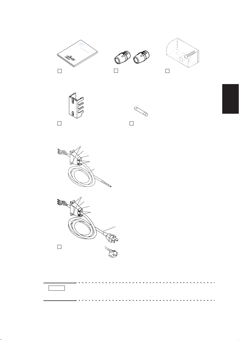
MODEL 700W
O
R
e
P
gu
A
1
N
7
5
P
W
A
A
M
P
N
O
S
A
D
P
1
N
E
A
6
L
3
6
-
N
5
1
0
0
0
W
P
1
3
A
1
A
M
A
P
0
N
O
A
-
D
1
P
1
N
E
.5A
A
6
L
7
6
-
N
0
1
0
0
8
W
P
1
6
A
1
A
M
A
P
0
N
O
-
A
D
3
P
1
N
E
A
A
6
L
P
6
-
N
3
A
0
0
1
1
-
N
P
1
A
0
1
0
0
A
0
2
0
P
P
A
W
-
5
N
A
5
A
0
P
M
A
P
N
N
-
A
O
2
AN
P
1
D
N
.
7
5
A
E
6
0
A
P
L
6
-
N
P
1
5
A
0
A
6
0
P
1
-
N
P
0
2
N
A
A
1
A
-
0
0
2
2
N
P
3
N
A
-
5
AN
1
5
6
0
7
0
-
0
2
0
A
4
0
0
1
-
.
-
5
8
A
6
2
A
A
0
A
P
-
A
3
P
N
.
5
A
A
P
3
N
AN
5
P
7
3
AN
0
0
1
1
A
6
5
3
0
A
5
7
0
A
3
.
5
A
P
E
R
P
a
r
t
AT
N
l
o
a
.
Z
ted
IO
1
0
0
2
N
D
-
e
3
2
r
C
2
M
i
,
es
IA
P
J
u
0
l
A
0
o
.
3
3
2
w
6
N
0
1
e
0
U
4
r
S
A
u
P
L
p
A
p
P
N
A
l
y
P
3
N
A
5
7
-
N
5
0
A
1
2
6
.5
0
A
1
3
A
5
10
-
5
A
A
A
Operation manual
[Z1-002-322]
Rear output terminal cover
(Mount on the unit. )
[Q5-000-170]
Guard cap 2pcs.
GP01-PMC
[83130]
Fuse
[99-00-1409]
(PAN35-20A:[99-00-0437])
Accompanying screwA:[M8-600-013]
Cable clamp:[P1-750-001]
Fastening plate:[D6-750-001]
Accompanying screwB:[M3-112-017]
Cable:[85-10-0630]
Accompanying screwA:[M8-600-013]
Cable clamp:[P1-750-001]
Fastening plate:[D6-750-001]
Accompanying screwB:[M3-112-017]
Cable with plug
Plug: NEMA5-15
[85-10-0660]
AC power cable
(with cable clamp)
Plug: CEE7/7
[85-10-0660]
Plug: CB1002
Fig.1-3 Accessories (model 700W)
Auxiliary output
terminal cover
Cover:[P1-000-047]
Screw:[M3-112-019]
Chap.1
1
Setup
PAN35-20A
(with no plug)
PAN16-30A
PAN60-10A
PAN70-8A
PAN110-5A
PAN160-3.5A
PAN250-2.5A
The power cord that is
provided varies depending
on the destination for the
product at the
factory-shipment.
NOTE
• We recommend that all packing materials be saved, in case
the product needs to be transported at a later date.
PAN-A 1-3
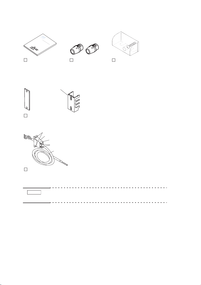
MODEL 1000W
O
P
R
E
e
R
P
P
g
a
A
r
u
t
AT
1
N
N
l
7
o
a
5
.
W
P
-A
Z
t
e
1-
IO
AN
M
P
0
d
O
0
S
AN
2
D
N
P
D
-
1
er
3
E
AN
2
6
L
C
2
3
M
6
i
-
,
50
e
1
I
0
J
A
Po
0
W
s
u
P
11
-3
0
A
A
l.
0
AN
M
3
A
P
0
3
2
w
O
6
N
AN
-
0
1
D
1
P
e
1
0
E
.
U
A
5
6
4
L
r
7
6
A
-1
N
00
Sup
A
0
8
W
P
11
6
P
A
L
AN
M
A
AN
P
0
O
pl
P
-
AN
D
3
AN
P
1
y
E
A
P
3
AN
6
L
A
P
5
6
-3
7
AN
-5
N
0
0
0
1
11
-1
A
P
A
00
1
-2
0
AN
6
0
2
0
P
.
P
A
0
W
5
-
5
AN
5
AN
A
0
P
M
1
A
P
3
-
AN
A
O
2.
A
5
P
1
D
7
-
N
5
AN
E
1
6
0
A
P
L
6
-5
0
P
1
-5
AN
0
A
AN
6
0
P
11
-
A
P
0
2
A
AN
AN
-2
0
0
2
P
3
A
-
5
A
A
1
5
6
0
7
0
-
N
0
2
0
A
4.
0
0
1
-
5
8
A
6
2
A
A
0
A
P
-3
AN
P
.
5
AN
A
P
3
A
5
P
7
-
N
3
A
0
0
1
-1
N
A
6
5
3
0
A
5
-7
0
A
-3
.5
A
Operation manual
[Z1-002-322]
[Q5-000-170]
PAN16-50A
Rear output terminal cover
(Mount on the unit.)
Accompanying screwA:[M8-600-013]
Cable clamp:[P1-750-001]
Fastening plate:[D6-750-001]
Accompanying screwB:[M3-112-017]
Cable:[85-10-0630]
AC power cable
(with cable clamp)
Fig.1-4 Accessories (model 1000W)
NOTE
• We recommend that all packing materials be saved, in case
the product needs to be transported at a later date.
Guard cap 2 pcs.
GP01-PMC
[83130]
PAN35-30A
PAN60-20A
PAN70-15A
PAN110-10A
PAN160-7A
PAN250-4.5A
PAN350-3.5A
PAN600-2A
Auxiliary output terminal cover
(Not included for the PAN16-50A.)
Cover:[P1-000-047]
Screw:[M3-112-019]
1-4 PAN-A
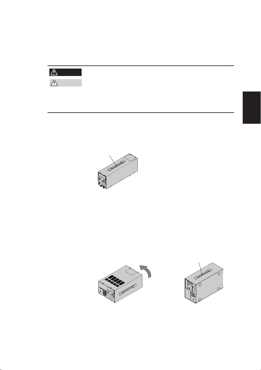
1.2 Precautions for moving
To carry the unit, hold the handle as shown below. When moving the
unit for a short distance, to the next room, for example, carry it on a
wagon whenever available.
WARNING
CAUTION
• For safety, check that the power switch is turned off.
• When transporting the product, be sure to use the
original packing materials.
• When packing the product, remove the power cable
and all other connection cables.
MODEL 175W
In the case of the model 175W, hold the handle located on the top.
Hold the handle.
Fig.1-5 Precaution for moving (model 175W)
MODEL 350W
In the case of the model 350W, the power transformer is located on
the left seen from the front, and the center of gravity of the unit is
deviated to the left. For carrying the unit, position the left side to be
bottom first as shown in Fig.1-6, and carry it with the handle.
Chap.1
Setup1
Hold the handle.Position the left side to the bottom.
Fig.1-6 Precaution for moving (model 350W)
PAN-A 1-5
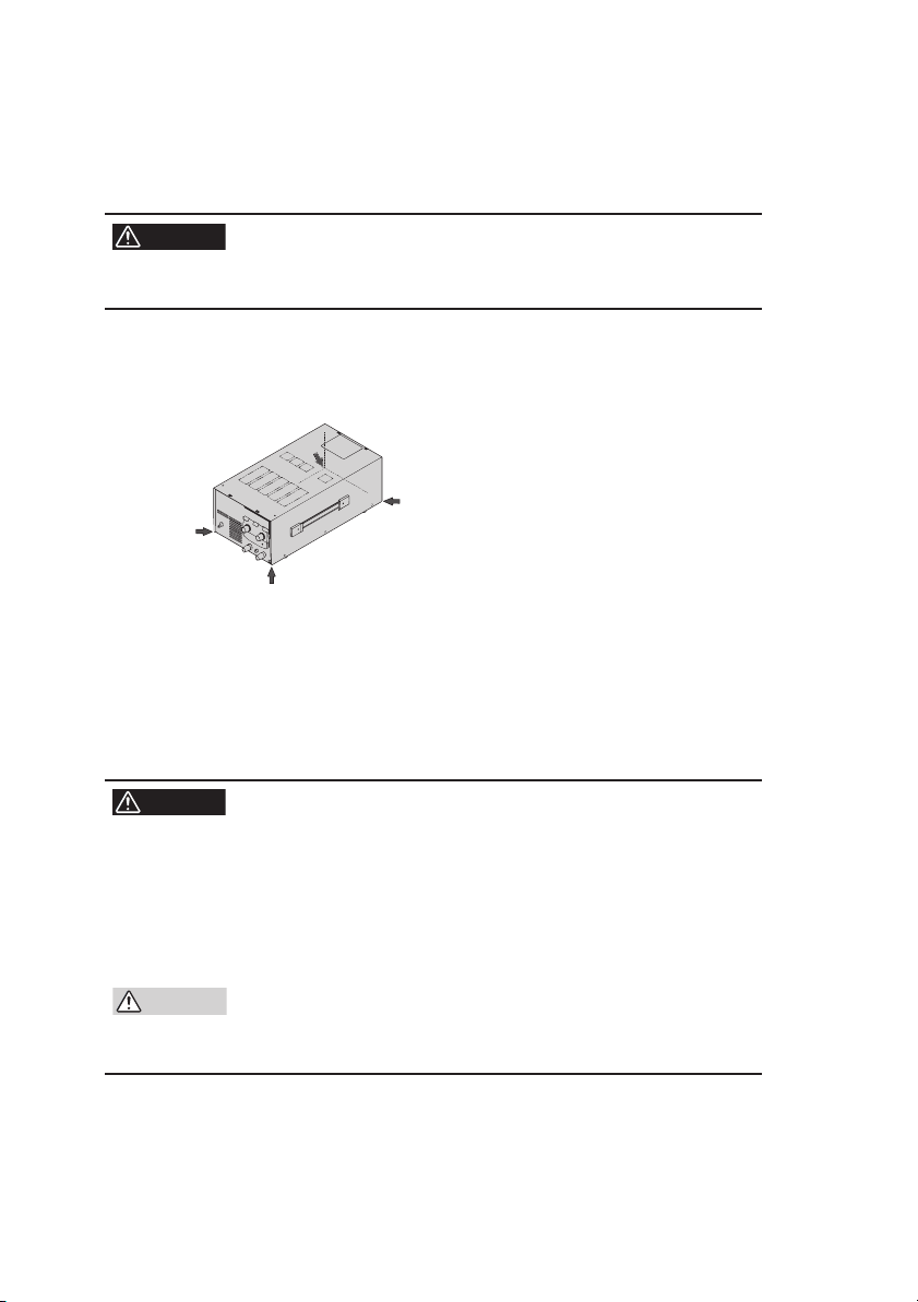
MODEL 700W
In the case of the model 700W, the power transformer is located on
the left seen from the front, and the center of gravity of the unit is
deviated to the left. For carrying the unit, take sufficient care.
WARNING
• The weight of the model 700W exceeds 20 kg. To
prevent any danger, never carry the unit by one person.
When moving the unit, two persons should hold the two locations at
the rear and front of the unit, respectively, as shown in Fig.1-7.
Two persons should hold the two locations
at the rear and front of the unit.
Fig.1-7 Precaution for moving (model 700W)
MODEL 1000W
In the case of the model 1000W, the power transformer is located on
the left seen from the front, and the center of gravity of the unit is
deviated to the left. For carrying the unit, take sufficient care.
WARNING
• The weight of the model 1000W exceeds 30 kg. To
prevent any danger, never carry the unit by one person.
• Holding the handles of the unit with the cable clamp
mounted can be difficult. Therefore, when moving
the unit, always remove the cable clamp and disconnect the AC power code.
CAUTION
• Before placing the unit upright, always remove the
cable clamp and AC power code; otherwise, the
clamp may be damaged.
1-6 PAN-A
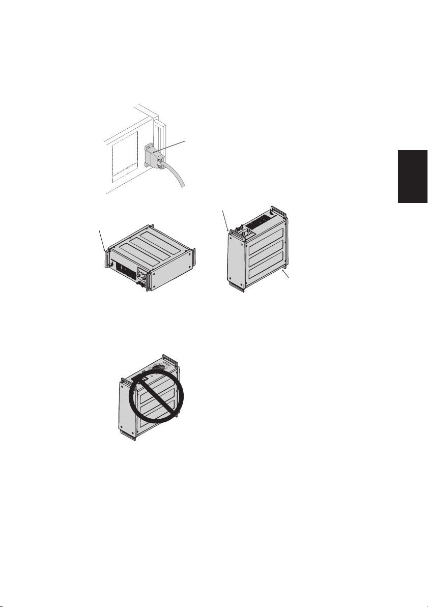
To carry the unit, hold handles on the front panel and rear panel with
two persons or more, or stand the unit as shown in Fig.1-8, and hold
handles on the front panel with two persons. After moving, quickly
place the unit with its bottom underneath.
Remove the cable clamp and AC
power cable from the rear panel
before moving the unit.
Hold the handles.
Hold the handles.
Remove the cable clamp and AC
power cable from the rear panel.
To carry the unit in a
horizontal position, two or
more persons should hold
the handles in four places.
O
N
S
S
E
S
N
S
1
2
7
8
1
3
O
U
T
P
U
T
S
E
R
I
E
S
S
C
I
V
G
-
V
C
V
-
R
C
C
C
1
-
O
V
W
0
N
C
1
I
R
C
T
1
-
R
E
1
R
2
O
S
1
O
L
T
C
3
U
R
T
O
1
T
I
E
S
M
4
P
O
L
R
1
-
(
N
A
G
C
S
M
5
/
V
O
L
O
A
1
I
E
A
N
S
M
F
6
G
2
V
L
F
A
1
(
E
E
A
M
S
7
L
2
V
L
A
F
)
1
E
A
M
S
8
O
C
1
V
T
A
1
R
E
O
E
N
9
S
N
9
1
R
C
m
C
T
N
)
A
I
E
N
C
O
N
m
N
R
L
C
O
N
T
P
E
O
M
N
H
U
T
T
U
C
E
E
T
E
O
T
T
C
C
P
O
R
E
P
O
T
P
O
A
B
M
N
I
D
R
N
O
V
O
W
O
IN
C
O
T
T
O
W
N
T
E
A
R
A
A
H
T
S
O
I
W
E
R
D
R
O
L
E
B
E
E
S
R
I
D
L
G
C
T
L
C
C
E
R
E
H
D
E
R
C
T
L
A
U
B
R
E
O
I
O
E
A
B
R
V
E
F
V
A
C
B
U
R
E
L
F
E
I
N
R
C
T
L
N
E
O
O
L
O
E
I
R
Y
P
E
.
D
N
R
M
T
A
A
O
.
G
D
E
O
R
N
R
A
N
I
R
T
H
S
T
E
E
C
I
C
H
O
C
A
L
M
G
O
O
N
S
T
O
M
N
Q
U
D
E
N
H
V
D
U
U
T
R
L
N
N
O
E
A
S
L
T
I
M
E
C
N
L
T
E
C
E
C
I
K
I
G
T
O
R
N
F
B
T
,
V
I
M
A
O
E
I
E
L
N
I
E
L
N
R
I
D
-
P
R
P
O
S
U
P
S
U
F
W
T
E
,
T
R
R
I
T
P
E
S
C
O
F
O
H
E
W
N
-
R
N
E
E
R
L
.
A
C
I
N
To carry the unit in an upright
position, the front panel handles
should be held by two persons.
Do not leave the unit in the
upright position.
To prevent damage to the
auxiliary terminal cover, avoid
placing on the front panel.
Chap.1
Setup1
Fig.1-8 Precaution for moving (model 1000W)
PAN-A 1-7

1.3 Precautions for installation
Be sure to observe the following precautions when installing the unit.
■ Do not use the unit in a flammable atmosphere.
To prevent explosion or fire, do not use the unit near alcohol or thinner, or in an atmosphere containing such vapors.
■ Avoid locations where the unit is exposed to high temperature or direct sunshine.
Do not locate the unit near a heater or in areas subject to drastic temperature changes.
Operation temperature range: 0 ˚C to 40 ˚C (32 ˚F to 104 ˚F)
Storage temperature range: -10 ˚C to 60 ˚C (14 ˚F to 140 ˚F)
■ Avoid locations of high humidity.
Do not locate the unit in high-humidity locations, i.e., near a boiler,
humidifier, water supply, etc.
Operation humidity range: 10 % to 90 % RH
Storage humidity range: 0 % to 90 % RH
Dew condensation may take place even in the operation humidity
range. In such a case, do not use the unit until the dew dries up completely.
■ Do not place the unit in a corrosive atmosphere.
Do not install the unit in a corrosive atmosphere or one containing
sulfuric acid mist, etc. This may cause corrosion of various conductors and imperfect contact with connectors, malfunction and failure,
or in the worst case, a fire.
Modification may allow the unit to cope with such an atmosphere. If
the unit is to be used in such an atmosphere, contact your Kikusui
agent.
■ Do not locate the unit in a dusty location.
Otherwise, this may result in electrical shock or fire.
■ Do not use the unit where ventilation is poor.
The unit employs a forced air cooling system. Air is taken in from
intake ports located on the unit's sides and front, and is exhausted
from the rear. Prepare sufficient space around the unit so that the
intake ports and exhaust port are always completely unobstructed.
Do not install the unit with its front panel positioned upward or downward.
1-8 PAN-A

■ Do not install the unit along a tilted section of floor or in a
location subject to vibrations.
If placed on a non-level surface or in a location subject to vibration,
the unit may fall, resulting in damage and injury.
■ Do not use the unit in locations affected by strong magnetic and/or electric fields.
Operation in a location subject to magnetic or electric fields may
cause the unit to malfunction resulting in electrical shock or fire.
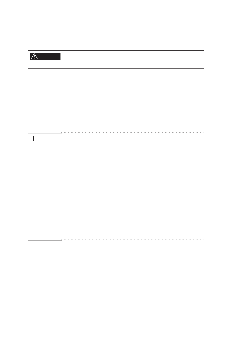
1.4 Checking the input fuse
MODEL 350W/700W
Use an input fuse element suitable for the AC power source. A seal is
attached to the rear panel indicating suitable fuse ratings. See Fig.1-9.
Chap.1
Setup1
WARNING
CAUTION
• To avoid electric shock, always disconnect the AC
power code or turn off the switch on the switchboard.
• Select a fuse element of external design, rating and
characteristics suitable for the unit. Use of a fuse of
different rating or a short circuit of the fuse holder
may damage the unit.
Fuse holder
CONTROL
19
14
13
8
7
OUTPUT
2
1
S
S
SENS
ON
OFF
AC IN
FUSE
10A 125V/250V
WARNING
REPLACE ONLY WITH
SAME
TYPE AND
RATINGS OF FUSE.
WEIGHT Kg
AC INPUT
100V 50/60Hz
MAX VA
AC IN connector
Fig.1-9 Rear panel (model 350W)
PAN-A 1-9
MODEL 175W/1000W
The input fuses of the models 175W and 1000W are located inside,
and users are not able to check or replace them.
WARNING
• Users are requested to never remove the cover and
check or replace the fuse.
1.5 Connecting the AC power code
Connect the AC power code to an AC power source specified for the
unit. A seal is attached to the rear panel indicating the rated input. See
Fig.1-9.
This product is an equipment of IEC Overvoltage Category II
(energy-consuming equipment supplied from the fixed installation).
NOTE
• Do not use the AC power code provided with the product as a
AC power code for other instruments.
MODEL 175W/350W
• In an emergency, the AC power cord with a plug may be used
to disconnect the product from the AC line in an emergency.
Connect the plug to an easily accessible outlet so that the plug
can be removed from the outlet at any time. Be sure to allow
enough space around the outlet.
MODEL 700W/1000W
• In an emergency, the POWER switch of the models 175W
and 1000W may be used to disconnect the product from the
AC line in an emergency. Be sure to allow enough space
around the outlet so that the POWER switch can be turned off
at any time.
Connecting procedure of PAN-A series side
MODEL 175W/350W
1. Insert the supplied AC power code into the AC IN connector on the rear panel.
1-10 PAN-A
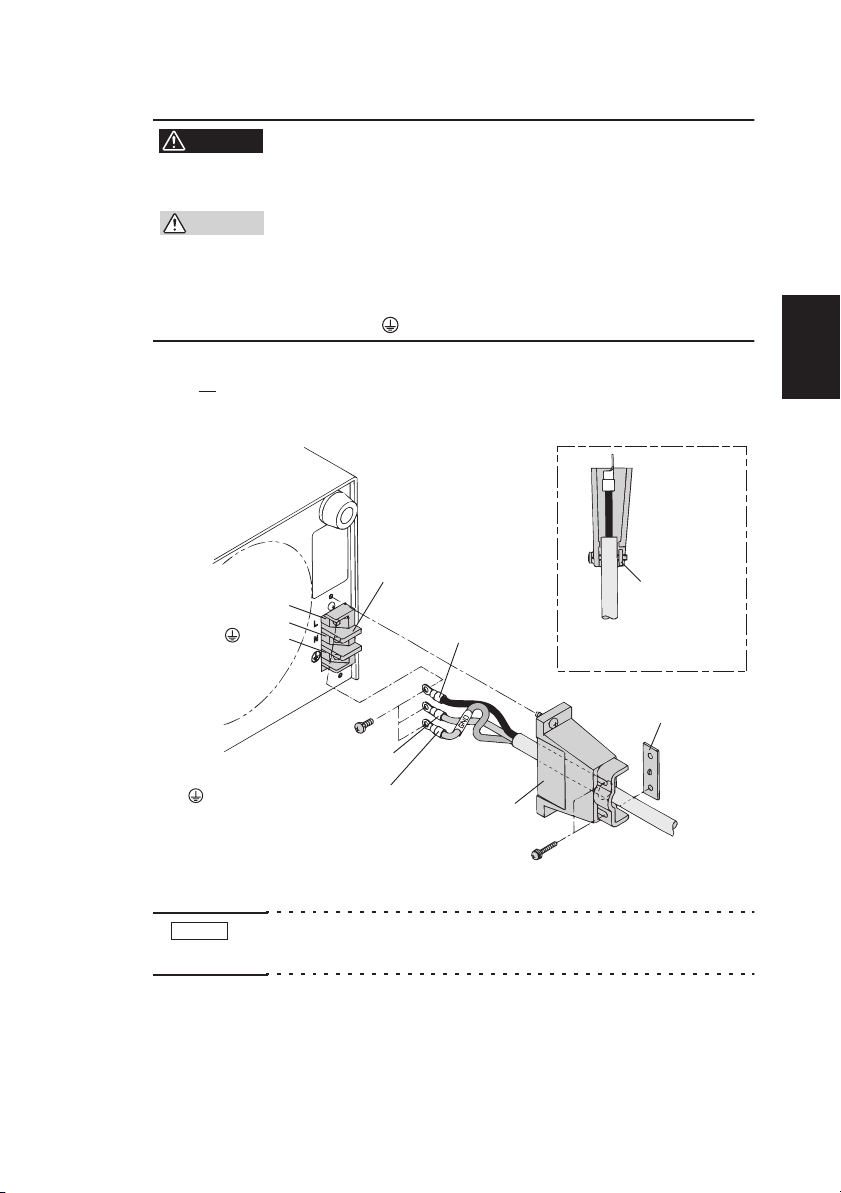
MODEL 700W/1000W
WARNING
• To avoid electric shock, first connect the cable to the
AC IN terminal board before connecting it to the
power source.
CAUTION
• Inside the unit, protective circuits including input
fuses are connected in order to meet the input terminal rating. Confirm that the wires of the specified
color are connected to the corresponding terminals
(L, N, and (GND)).
1.
Connect the supplied AC power code to the terminal board
as shown in Fig.1-10.
(GND)
N
AC IN
L
terminal board
L: Black or Brown
Attach a covered part of
the AC power cable with
a fastening plate.
Fastening plate
Fastening plate
Chap.1
Setup1
N: White or Blue
(GND): Green or Green/Yellow
(Not included for Model
Cable clamper
175W and 350W.)
Fig.1-10 Connection of AC power code
NOTE
• Fig.1-10 shows the connections on the model 700W. Connections on model 1000W can be performed in the same manner.
PAN-A 1-11
Connecting procedure of AC power source side
MODEL 175W/350W/700W(Except PAN35-20A)
1. Insert the plug of the AC power code into an outlet.
■ If the supplied AC power code has no plug:
Models that have had their rated inputs changed according to a factory option, i.e., those other than 100 V AC input models, may come
with no plugs. Attach a suitable plug to the AC power code, then connect the cable to the outlet.
CAUTION
• Inside the unit, protective circuits including input
fuses are connected in order to meet the input terminal rating. When attaching a plug to the AC power
code, refer to Fig.1-11 and confirm that the wires of
the specified color are connected to the correspond-
ing terminals (L, N, and (GND)). (This connection
must be performed by qualified personnel.)
1-12 PAN-A
 Loading...