

Kikusui OT01-PCR4000LA/2, OT01-PCR8000LA/2, OT01-PCR12000LA/2 Operation Manual
Part No. Z1-002-892, IB004473
Feb. 2008
OPERATION MANUAL
OUTPUT EXPANSION KIT
PCR-LA Series
OT01-PCR4000LA/2
OT01-PCR8000LA/2
OT01-PCR12000LA/2

Use of Operation Manual
Please read through and understand this Operation Manual before operating the product. After reading,
always keep the manual nearby so that you may refer to it as needed. When moving the product to another
location, be sure to bring the manual as well.
If you find any incorrectly arranged or missing pages in this manual, they will be replaced. If the manual
gets lost or soiled, a new copy can be provided for a fee. In either case, please contact Kikusui distributor/
agent, and provide the “Kikusui Part No.” given on the cover.
This manual has been prepared with the utmost care; however, if you have any questions, or note any
errors or omissions, please contact Kikusui distributor/agent.
Reproduction and reprinting of this operation manual, whole or partially, without our permission is prohibited.
Both unit specifications and manual contents are subject to change without notice.
Copyright© 2003-2008 Kikusui Electronics Corporation
Safety Symbols
For the safe use and safe maintenance of this product, the following
symbols are used throughout this manual and on the product. Understand the meanings of the symbols and observe the instructions they
indicate (the choice of symbols used depends on the products).
Indicates that a high voltage (over 1000 V) is used here. Touch-
OR
ing the part causes a possibly fatal electric shock. If physical
contact is required by your work, start work only after you make
sure that no voltage is output here.
DANGER
WARNING
CAUTION
Indicates an imminently hazardous situation which, if ignored,
will result in death or serious injury.
Indicates a potentially hazardous situation which, if ignored,
could result in death or serious injury.
Indicates a potentially hazardous situation which, if ignored, may
result in damage to the product and other property.
Shows that the act indicated is prohibited.
Is placed before the sign “DANGER,” “WARNING,” or “CAUTION” to emphasize these. When this symbol is marked on the
product, see the relevant sections in this manual.
Indicates a protective conductor terminal.
Indicates a chassis (frame) terminal.
OT01-PCR-LA/2 Safety Symbols I
Operation
Manual
Line
Voltage
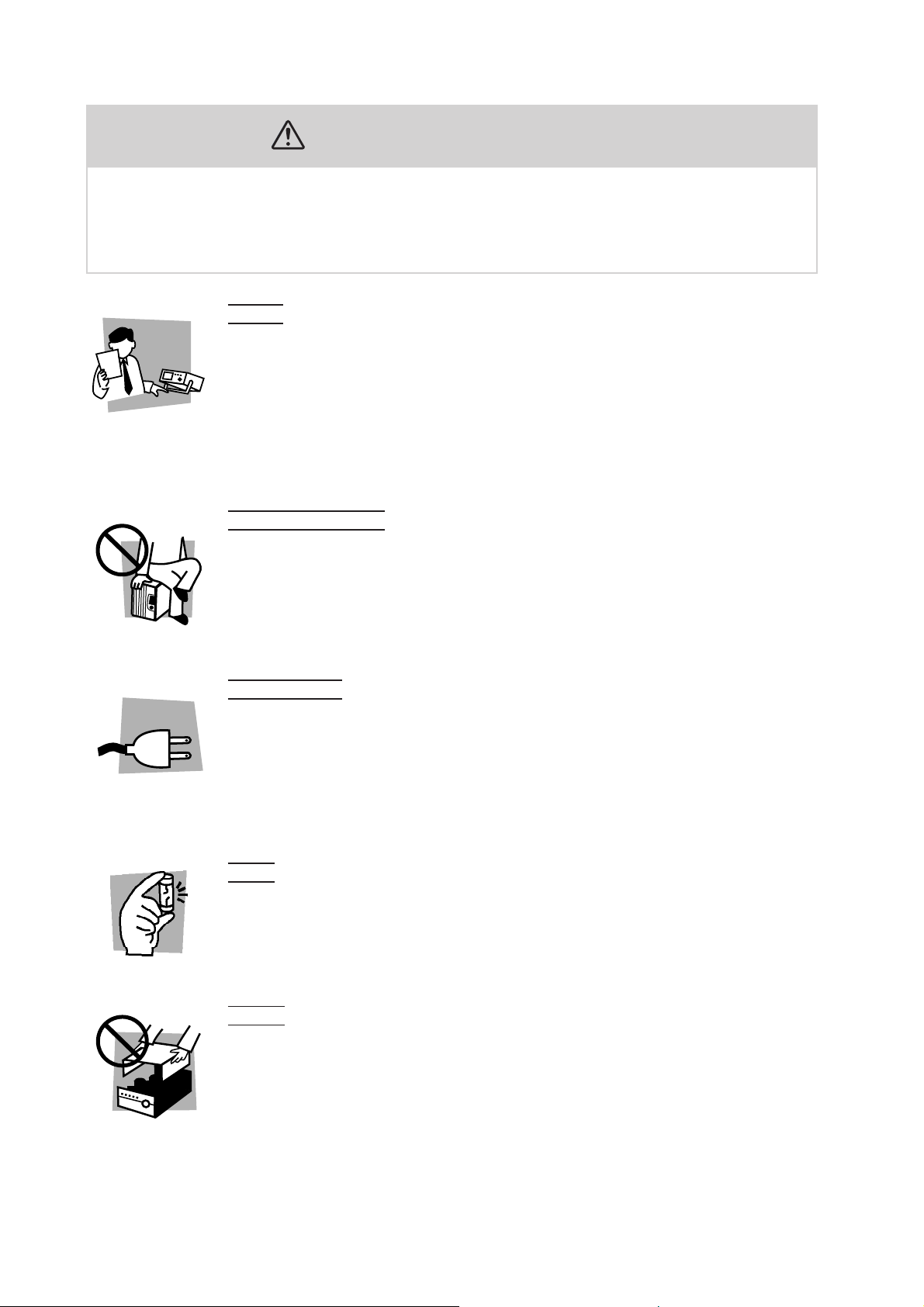
Safety Precautions
The following are safety precautions to be observed in order to avoid fire hazard,
electric shock, accidents, and other failures. It is not possible to predict all potential hazards; however, the following describes all known possible hazardous conditions. Keep them in mind and make sure that all of them are observed properly.
User
s
• This product must be used only by qualified personnel who understand the contents of this operation manual.
• If it is handled by disqualified personnel, personal injury may result. Be sure to handle it under supervision of qualified personnel (those who have electrical knowledge.)
• This product is not designed or manufactured for general home or consumer use.
Purposes of use
• Do not use the product for purposes other than those described in the operation
manual.
Input po
• Use the product with the specified input power voltage.
• For applying power, use the power cable provided. Note that the provided power
cable is not use with some products that can switch among different input power
voltages or use 100 V and 200 V without switching between them. In such a case,
use an appropriate power cable.
wer
Fuse
• With products with a fuse holder on the exterior surface, the fuse can be replaced
with a new one. When replacing a fuse, use the one which has appropriate shape,
ratings, and specifications.
ver
Co
• There are parts inside the product which may cause physical hazards. Do not
remove the external cover.
II Safety Precautions OT01-PCR-LA/2
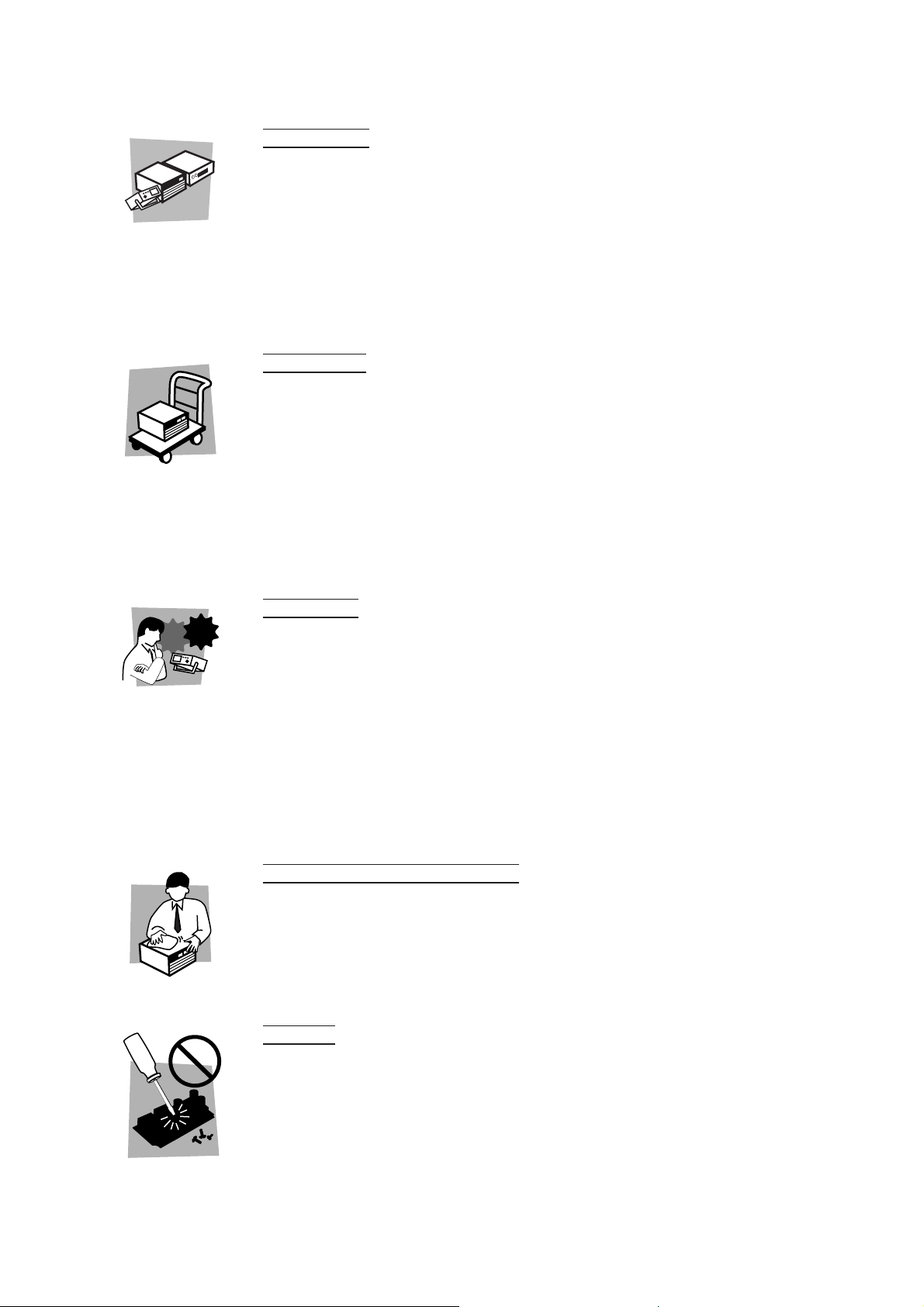
Installation
• When installing products be sure to observe “Installation” described in this manual.
• To avoid electrical shock, connect the protective ground terminal to electrical
ground (safety ground).
• When connecting the power cable to a switchboard, be sure work is performed by
a qualified and licensed electrician or is conducted under the direction of such a
person.
• When installing products with casters, be sure to lock the casters.
Relocation
• Turn off the power switch and then disconnect all cables when relocating the
product.
• Use two or more persons when relocating the product which weights more than
20 kg. The weight of the products can be found on the rear panel of the product
and/or in this operation manual.
• Use extra precautions such as using more people when relocating into or out of
present locations including inclines or steps. Also handle carefully when relocating tall products as they can fall over easily.
• Be sure the operation manual be included when the product is relocated.
Check?
Operation
• Check that the AC input voltage setting and the fuse rating are satisfied and that
there is no abnormality on the surface of the power cable. Be sure to unplug the
power cable or stop applying power before checking.
• If any abnormality or failure is detected in the products, stop using it immediately.
Unplug the power cable or disconnect the power cable from the switchboard. Be
careful not to allow the product to be used before it is completely repaired.
• For output wiring or load cables, use connection cables with larger current capacity.
• Do not disassemble or modify the product. If it must be modified, contact Kikusui
distributor/agent.
Maintenance and c
• To avoid electrical shock, be absolutely sure to unplug the power cable or stop
applying power before performing maintenance or checking.
• Do not remove the cover when performing maintenance or checking.
• To maintain performance and safe operation of the product, it is recommended
that periodic maintenance, checking, cleaning, and calibration be performed.
vice
Ser
hecking
• Internal service is to be done by Kikusui service engineers. If the product must be
adjusted or repaired, contact Kikusui distributor/agent.
OT01-PCR-LA/2 Safety Precautions III

Arrangement of this manual
This Operation Manual is made up of the following sections.
Chapter 1 General
Provides an overview and describes the features of the Single-phase/Single-phase,
Three-wire Output Expansion Kits.
Chapter 2 Installation and Preparation for Use
Describes the procedures necessary for unpacking the product for preparation prior
to use.
Chapter 3 Output Switching (Operation of the Output Terminal)
Describes output-switching operations of the Output Terminal configured as a single phase/Single-phase, three-wire switching system.
Chapter 4 Part Names and Functions (Output Terminal)
Denotes the names of switches, displays, terminals, and other parts on the front and
rear panels of the Output Terminal. Also describes their functions.
Chapter 5 Single-phase Parallel Operation (Operations of PCR-LA
AC Power Supplies)
Describes the procedure for operation of the PCR-LA power supplies in singlephase parallel operation. For the method of operating a PCR-LA power supply singly, see the PCR-LA AC Power Supply Operation Manual.
Chapter 6 Single-phase, Three-wire Operation (Operations of PCR-
LA AC Power Supplies)
Describes the procedure for operation of the PCR-LA power supplies in singlephase, three-wire operation. For the method for operating a PCR-LA power supply
singly, see the PCR-LA AC Power Supply Operation Manual.
Chapter 7 Maintenance
Describes the maintenance procedure for the system, including the PCR-LA AC
power supplies. Also explains the remedies against possible malfunctions encountered during use of the system.
Chapter 8 Specifications
Shows the specifications and accessories for the Output Expansion Kits.
IV Arrangement of this manual OT01-PCR-LA/2

Contents
Safety Symbols ____________________________________________ I
Safety Precautions ________________________________________ II
Arrangement of this manual ________________________________ IV
Chapter 1 General 1-1
1.1 Outline of the Product - - - - - - - - - - - - - - - - - - - - - - - - - - - - - - - - - - - 1-2
1.2 Features - - - - - - - - - - - - - - - - - - - - - - - - - - - - - - - - - - - - - - - - - - - - - 1-3
1.3 Outline of the Operating Sections - - - - - - - - - - - - - - - - - - - - - - - - - - - 1-4
1.4 The Applicable ROM Version of the PCR-LA - - - - - - - - - - - - - - - - - - - - 1-5
1.5 Combination of Options - - - - - - - - - - - - - - - - - - - - - - - - - - - - - - - - - - 1-5
Chapter 2 Installation and Preparation for Use 2-1
2.1 Check at Unpacking - - - - - - - - - - - - - - - - - - - - - - - - - - - - - - - - - - - - - 2-2
2.2 Precautions on Installation - - - - - - - - - - - - - - - - - - - - - - - - - - - - - - - - 2-6
2.3 Moving Precautions - - - - - - - - - - - - - - - - - - - - - - - - - - - - - - - - - - - - - 2-7
2.4 Grounding - - - - - - - - - - - - - - - - - - - - - - - - - - - - - - - - - - - - - - - - - - - 2-8
2.5 Connections for a Single-phase/
Single-phase, Three-wire Switching System - - - - - - - - - - - - - - - - - - - - 2-8
2.5.1 Input Power of PCR-LA Power Supplies (Two Units) - - - - - - - - 2-9
2.5.2 Connection of Power Connection Cables - - - - - - - - - - - - - - - - - 2-12
2.5.3 Signal Connection Cables - - - - - - - - - - - - - - - - - - - - - - - - - - 2-15
2.5.4 Parallel Operation Driver - - - - - - - - - - - - - - - - - - - - - - - - - - - 2-17
2.5.5 Single-phase, Three-wire Output Driver - - - - - - - - - - - - - - - - - 2-19
2.5.6 Summary of System Connections - - - - - - - - - - - - - - - - - - - - - 2-20
2.6 Power ON - - - - - - - - - - - - - - - - - - - - - - - - - - - - - - - - - - - - - - - - - - 2-22
2.7 Operation Check - - - - - - - - - - - - - - - - - - - - - - - - - - - - - - - - - - - - - - 2-24
2.7.1 Single-phase Parallel Operation - - - - - - - - - - - - - - - - - - - - - - - 2-24
2.7.2 Single-phase, Three-wire Operation - - - - - - - - - - - - - - - - - - - - 2-25
2.8 Connecting a Load - - - - - - - - - - - - - - - - - - - - - - - - - - - - - - - - - - - - 2-26
Chapter 3 Output Switching
(Operation of the Output Terminal) 3-1
3.1 Panel Operation - - - - - - - - - - - - - - - - - - - - - - - - - - - - - - - - - - - - - - - 3-2
3.1.1 Single-phase Parallel Operation - - - - - - - - - - - - - - - - - - - - - - - - 3-2
3.1.2 Single-phase, Three-wire Operation - - - - - - - - - - - - - - - - - - - - - 3-3
3.1.3 Shutting Down the Power in an Emergency - - - - - - - - - - - - - - - - 3-3
3.2 External Control - - - - - - - - - - - - - - - - - - - - - - - - - - - - - - - - - - - - - - - 3-4
Chapter 4 Part Names and Functions
(Output Terminal) 4-1
4.1 OT01-PCR4000LA/2 - - - - - - - - - - - - - - - - - - - - - - - - - - - - - - - - - - - - 4-2
4.1.1 Front Panel - - - - - - - - - - - - - - - - - - - - - - - - - - - - - - - - - - - - - - 4-2
OT01-PCR-LA/2 Contents V

4.1.2 Rear Panel - - - - - - - - - - - - - - - - - - - - - - - - - - - - - - - - - - - - - 4-3
4.2 OT01-PCR8000LA/2 or OT01-PCR12000LA/2 - - - - - - - - - - - - - - - - - - 4-5
4.2.1 Front Panel - - - - - - - - - - - - - - - - - - - - - - - - - - - - - - - - - - - - - 4-5
4.2.2 Rear Panel - - - - - - - - - - - - - - - - - - - - - - - - - - - - - - - - - - - - - - 4-6
Chapter 5 Single-phase Parallel Operation
(Operations of PCR-LA AC Power Supplies) 5-1
5.1 Basic Operations - - - - - - - - - - - - - - - - - - - - - - - - - - - - - - - - - - - - - - - 5-2
5.2 Setting Limit Values - - - - - - - - - - - - - - - - - - - - - - - - - - - - - - - - - - - - 5-2
5.3 Steps to be Taken in the Event of an Alarm - - - - - - - - - - - - - - - - - - - - - 5-3
5.4 Ammeter’s Zero Calibration Function - - - - - - - - - - - - - - - - - - - - - - - - - 5-6
5.4.1 Zero Calibration Procedure When Using RC04-PCR-LA - - - - - - 5-6
5.4.2 Messages Available When Using the RS-232C or GPIB Interface 5-7
Chapter 6 Single-phase, Three-wire Operation
(Operations of PCR-LA AC Power Supplies) 6-1
6.1 Basic Operations - - - - - - - - - - - - - - - - - - - - - - - - - - - - - - - - - - - - - - - 6-2
6.2 Switching of Output Voltage Display - - - - - - - - - - - - - - - - - - - - - - - - - 6-2
6.3 Output Voltage Setting - - - - - - - - - - - - - - - - - - - - - - - - - - - - - - - - - - - 6-3
6.4 Limit Value Setting - - - - - - - - - - - - - - - - - - - - - - - - - - - - - - - - - - - - - 6-4
6.5 Current/Power Display Mode - - - - - - - - - - - - - - - - - - - - - - - - - - - - - - 6-4
6.6 Memory Function - - - - - - - - - - - - - - - - - - - - - - - - - - - - - - - - - - - - - - 6-5
6.7 Key-lock Function - - - - - - - - - - - - - - - - - - - - - - - - - - - - - - - - - - - - - - 6-5
6.8 Steps to be Taken in the Event of an Alarm - - - - - - - - - - - - - - - - - - - - - 6-6
6.9 Limitations on the PCR-LA Power Supplies - - - - - - - - - - - - - - - - - - - - 6-9
6.10 Using the Remote Controller - - - - - - - - - - - - - - - - - - - - - - - - - - - - - - - 6-9
6.10.1 Switching between Phase Voltage and Line Voltage Displays - - - 6-10
6.10.2 Displaying the V-Phase Current and Voltage - - - - - - - - - - - - - - 6-10
6.10.3 Switching to the Current or Power Display Mode - - - - - - - - - - - 6-11
6.10.4 Sequence Operation - - - - - - - - - - - - - - - - - - - - - - - - - - - - - - - 6-11
6.10.5 Harmonic Current Analysis Function - - - - - - - - - - - - - - - - - - - 6-11
6.11 Using the GPIB/RS-232C Interface - - - - - - - - - - - - - - - - - - - - - - - - - 6-12
6.11.1 Phase Voltage/Line Voltage Display Messages - - - - - - - - - - - - - 6-12
6.11.2 Output Voltage Setting Messages - - - - - - - - - - - - - - - - - - - - - 6-13
6.11.3 Output Measurement Messages - - - - - - - - - - - - - - - - - - - - - - - 6-15
6.11.4 Harmonic Current Analysis Messages - - - - - - - - - - - - - - - - - - - 6-17
Chapter 7 Maintenance 7-1
7.1 Maintenance - - - - - - - - - - - - - - - - - - - - - - - - - - - - - - - - - - - - - - - - - - 7-2
7.1.1 Cleaning the Panel Surface - - - - - - - - - - - - - - - - - - - - - - - - - - 7-2
7.1.2 Cleaning the Air-intake Filters in the PCR-LA Power Supplies - - 7-2
7.1.3 Inspecting the Power Connection Cables - - - - - - - - - - - - - - - - - 7-2
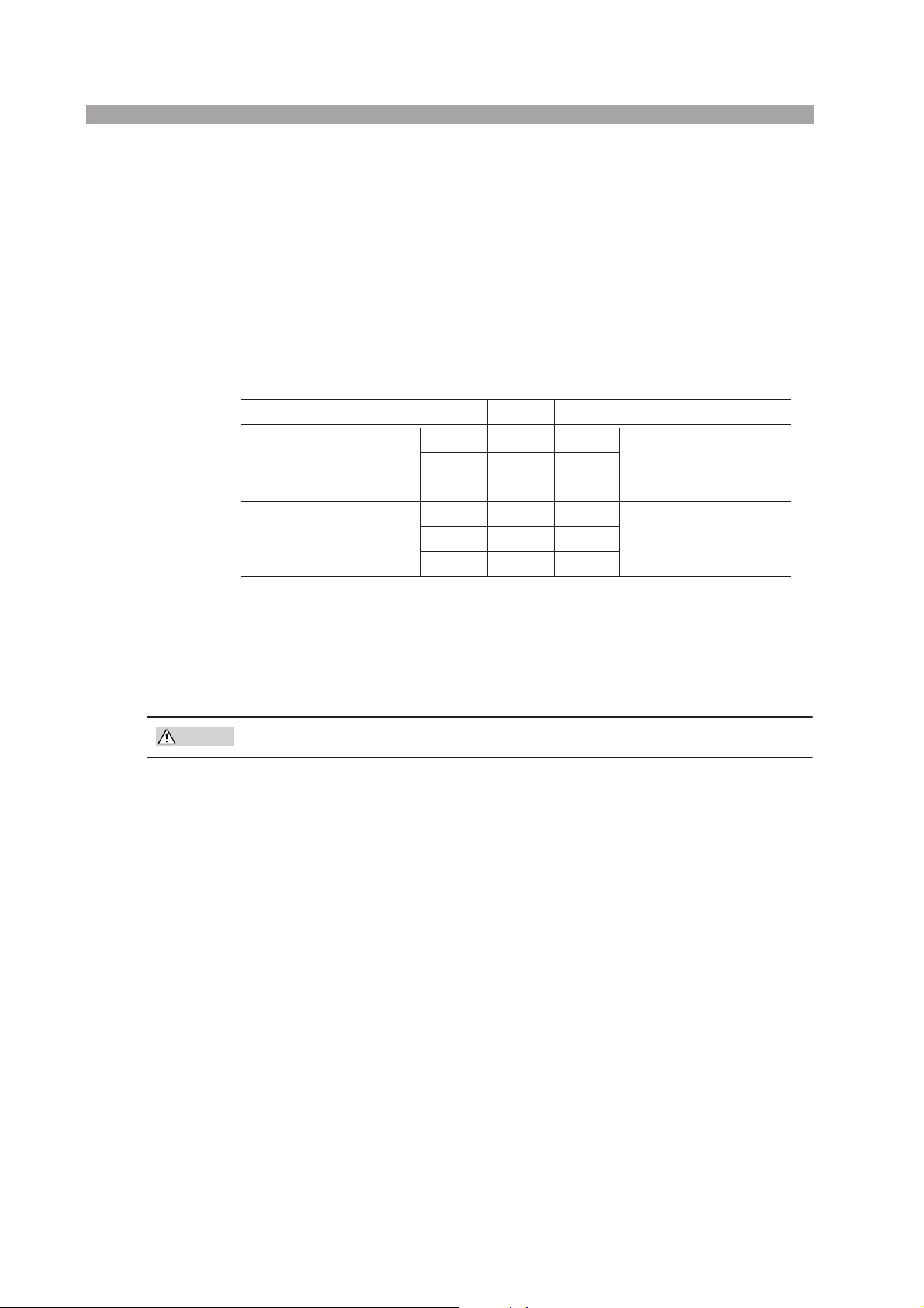
7.2 Malfunctions and Causes - - - - - - - - - - - - - - - - - - - - - - - - - - - - - - - - - 7-3
7.2.1 Single-phase Parallel Operation - - - - - - - - - - - - - - - - - - - - - - - 7-3
7.2.2 Single-phase, Three-wire Operation - - - - - - - - - - - - - - - - - - - - - 7-5
VI Contents OT01-PCR-LA/2

Chapter 8 Specifications 8-1
8.1 Specifications - - - - - - - - - - - - - - - - - - - - - - - - - - - - - - - - - - - - - - - - - 8-2
8.1.1 Output Expansion Kits (Single-phase/Single-phase, Three-wire Switch-
ing) - - - - - - - - - - - - - - - - - - - - - - - - - - - - - - - - - - - - - - - - - - 8-2
8.1.2 Parallel Operation - - - - - - - - - - - - - - - - - - - - - - - - - - - - - - - - - 8-2
8.1.3 Single-phase, Three-wire Operation - - - - - - - - - - - - - - - - - - - - - 8-3
8.2 Dimensions - - - - - - - - - - - - - - - - - - - - - - - - - - - - - - - - - - - - - - - - - - 8-4
Index 1- 1
OT01-PCR-LA/2 Contents VII

VIII Contents OT01-PCR-LA/2

1
1
Chapter 1 General
Provides an overview and describes the features of the Single-phase/Single-phase,
Three-wire Output Expansion Kits.
OT01-PCR-LA/2 General 1-1
■
1.1 Outline of the Product
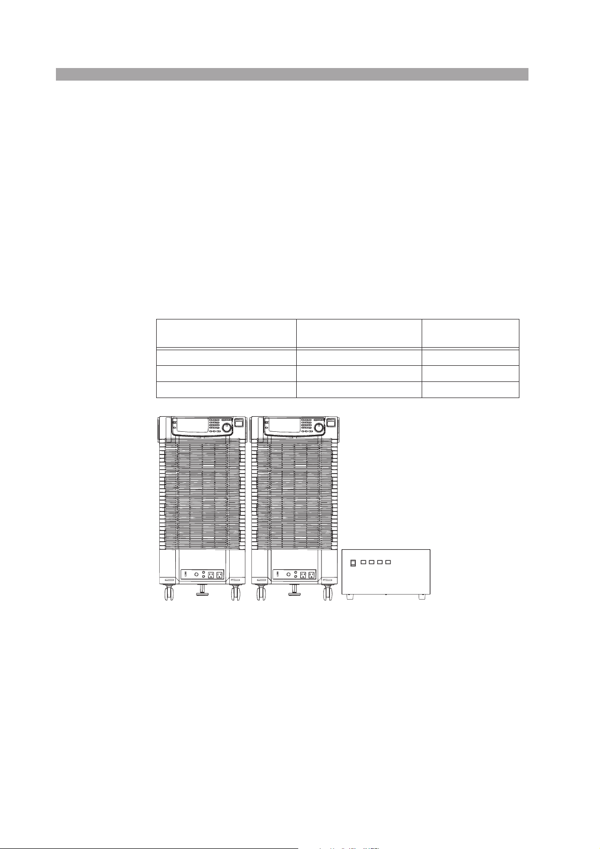
These products are Output Expansion Kits for the PCR-LA series AC power supplies. An output expansion kit enables configuration of a system capable of switching the outputs of multiple PCR-LA power supplies to obtain single- or singlephase, three-wire outputs. Output switching is performed at the Output Terminal
section. The customer should make connections between the respective units. All of
the cables required for connections are provided with the Output Expansion Kits.
A system is configured on the basis of the PCR-LA series single-phase output
power supplies. In single-phase parallel operations, two power supplies are operated
in parallel. In single-phase, three-wire operations, two power supplies generate outputs in respective phases.
List of the Output Expansion Kits
Model name
OT01-PCR4000LA/2 Two PCR2000LAs 4 kVA
OT01-PCR8000LA/2 Two PCR4000LAs 8 kVA
OT01-PCR12000LA/2 Two PCR6000LAs 12 kVA
Number of PCR-LA
power supplies
Rated output capacity
Two PCR4000LAs Output Terminal section
Fig. 1-1 Example of the Configuration of a Single-phase/Single-
phase, Three-wire Switching System, OT01-PCR8000LA/2
1-2 General OT01-PCR-LA/2

1.2 Features
Single-phase/single-phase, three-wire switching system
Single-phase/single-phase, three-wire switching can be achieved without modifying cable connections. The Output Terminal has dedicated output terminals
for single-phase and single-phase, three-wire, respectively, which is convenient for connecting and disconnecting a load.
Single-phase parallel operation
Control
A system of AC power supplies capable of generating high-quality, largecapacity output can be realized. The two PCR-LA power supplies are operated
in parallel, one slave unit of which is controlled by the master unit.
■
■
■
Single-phase, three-wire operation
Control
For single-phase, three-wire outputs, two AC power supplies are assigned to
the U- and V-phases, respectively. The U-phase unit controls the V-phase unit.
Phase voltage unbalance
Generally, all phase voltages are set in one operation, but it is also possible to
set phase voltages on a phase basis.
Line voltage measurements
The system is capable of measuring not only phase voltages but also line voltages.
Single-phase, three-wire power
The power and apparent power of a load can be displayed as the total value of
those measured by the two PCR-LA power supplies. The total power factor for
the single-phase three-wire is also calculated from the total of measured values. (Note that the measurement of apparent power or the power factor
requires the RS-232C Control, the optional RC04-PCR-LA, or the optional
IB03-PCR-LA.)
RC04-PCR-LA: Remote Controller
IB03-PCR-LA: GPIB Interface
OT01-PCR-LA/2 General 1-3
■
■
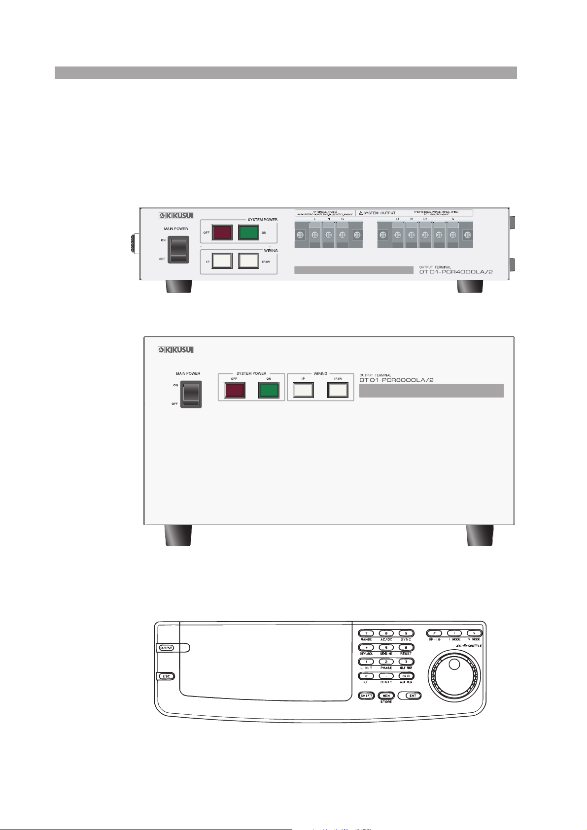
1.3 Outline of the Operating Sections
The operating sections are the front panel of the Output Terminal and the PCR-LA
AC power supply’s control panel.
Output Terminal’s front panel operating section
Fig. 1-2 OT01-PCR4000LA/2
Fig. 1-3 OT01-PCR8000LA/2 or OT01-PCR12000LA/2
PCR-LA power supply’s control panel operating section
Fig. 1-4 PCR-LA Power Supply’s Control Panel
1-4 General OT01-PCR-LA/2

1.4 The Applicable ROM Version of the PCR-LA
This Operation Manual applies to cases in which the expansion kit is connected to
PCR-LA AC power supplies with ROM of
version 3.35 or later.
When using above options with the PCR-LA in single-phase three-wire operation,
the PCR-LA must be required with the ROM version of 3.35 or later. If the ROM
version of the PCR-LA is 3.34 or previous version, the PCR-LA is required for the
ROM update.
To check the ROM version of the PCR-LA, refer to the operation manual of the
PCR-LA series.
In case, the PCR-LA needs the ROM update, contact your Kikusui agent or distributor.
When making an inquiry about the product, please provide us with the following
information:
• Model name of the PCR-LA power supplies
• ROM version of the PCR-LA power supplies
• Serial numbers and revision numbers of the PCR-LA power supplies (indicated
at the lower rear of the products)
• Model name of this expansion kit
• Serial number and revision number of the expansion kit (indicated at the rear of
the Output Terminal)
1.5 Combination of Options
The table below shows a combination of the options available. They can be installed
in the PCR-LA AC power supply in which the U-phase card has been installed.
Option name Model name
Remote Controller RC04-PCR-LA
GPIB Interface IB03-PCR-LA
OT01-PCR-LA/2 General 1-5

1-6 General OT01-PCR-LA/2

2
2
Chapter 2 Installation and
Preparation for Use
Describes the procedures necessary for unpacking the product for preparation prior
to use.
OT01-PCR-LA/2 Installation and Preparation for Use 2-1
2.1 Check at Unpacking
Upon receiving the product, confirm that the package contains the necessary accessories and has not been damaged during transportation.
If the output expansion kit is damaged or any accessory is missing, notify your
Kikusui distributor/agent.
■
■
NOTE
• We recommend that all packing materials be saved, in case the product needs to
be transported at a later date.
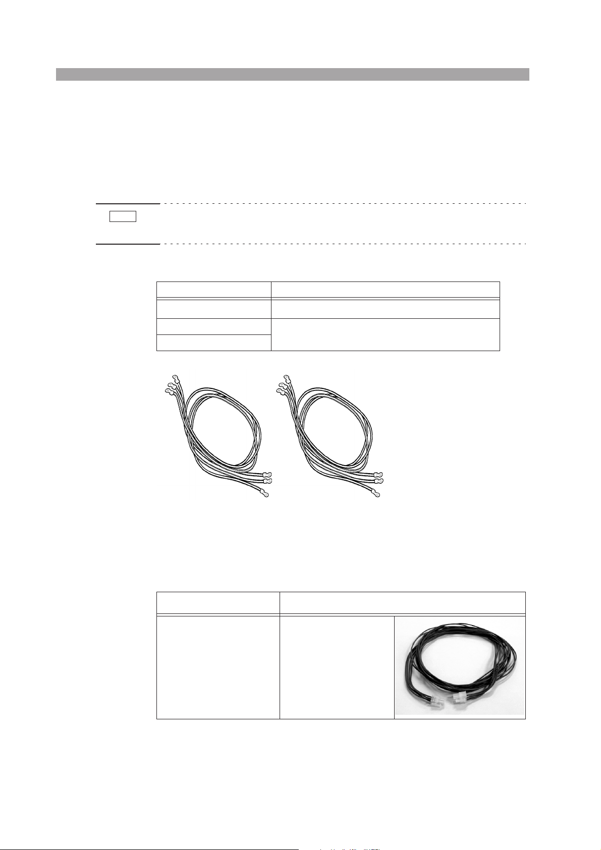
Power connection cables
Model name Description
14 mm
2
/2.5 m, 6 pcs. [91-80-7377 (three pcs.)x2]
2
/2.5 m, 6 pcs. [91-80-7524 (three pcs.)x2]
OT01-PCR4000LA/2
OT01-PCR8000LA/2
OT01-PCR12000LA/2
5.5 mm
Fig. 2-1 Power Connection Cables, Six
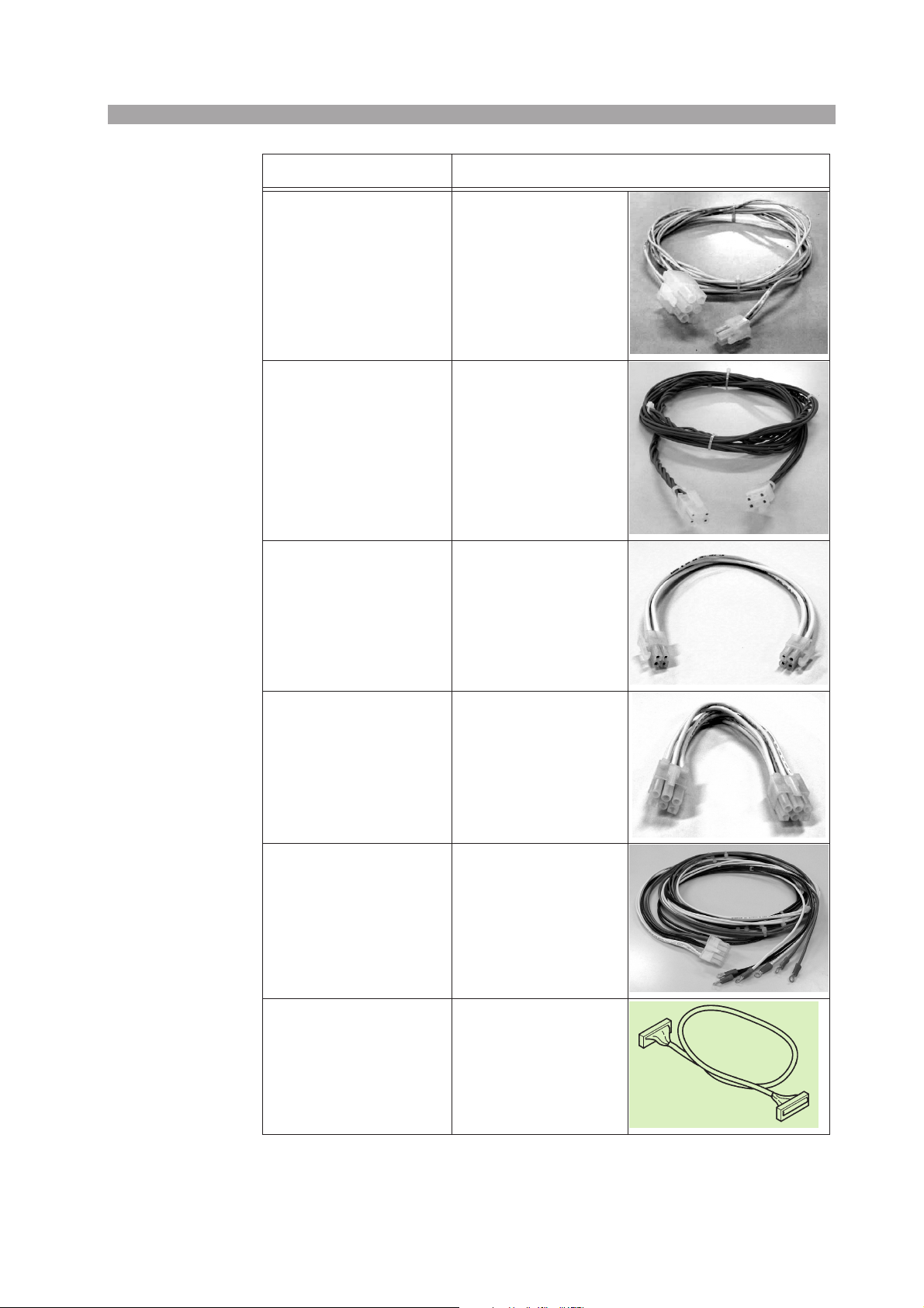
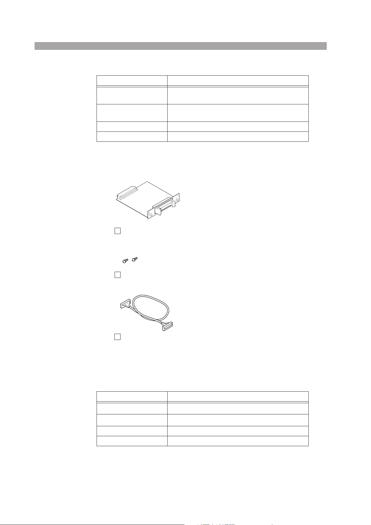
Signal connection cables
Part name Description
Signal connection cable 1
For OT01-PCR4000LA/2
[91-87-8154]
For master J1
(4 poles – 4 poles),
one
2-2 Installation and Preparation for Use OT01-PCR-LA/2
Part name Description
Signal connection cable 1
For OT01-PCR8000LA/2
For OT01-PCR12000LA/2
[91-87-8155]
Signal connection cable 2
(Common to each model)
[91-87-8156]
Signal connection cable 3
For OT01-PCR4000LA/2
[91-80-6900]
For master J1
(4 poles – 6 poles),
one
For J4
(6 poles – 6 poles),
two
For J3 to J1
(4 poles – 4 poles),
one
Signal connection cable 3
For OT01-PCR8000LA/2
For OT01-PCR12000LA/2
[91-80-6901]
Signal connection cable 4
(Common to each model)
[91-87-8167]
Signal connection cable 5
(Common to each model)
[91-88-4453]
For J3 to J1
(6 poles – 6 poles),
one
For sensing
(10 poles – 2 crimp
terminals),
one
For the parallel-operation
master
With connectors at both
ends
(26 poles; length: 2.5 m),
one
OT01-PCR-LA/2 Installation and Preparation for Use 2-3
■
■
Parallel Operation Driver: (common to each model)
Part name Description
Master-unit card
PD03M-OT01-PCR-LA
Slave-unit card
PD03S-OT01-PCR-LA
Drive-signal cable With drive-signal connectors (26 poles), one pc.
Mounting screw (M3) 4
*1 These boards are dedicated for the expansion kits and are used when the PCR-LA AC power
supplies are used in combination with the Output Terminal. They cannot be used for parallel
or single-phase, three-wire operations of PCR-LA power supplies only.
Master-unit card/slave-unit card (one each, total of two boards)
1
1
*1
M3x6
Card-mounting screws (two pcs. for each card, total of 4 pcs.)
[M3-101-001]
Drive-signal cable (26 poles; one pc.; length: 0.7 m)
[91-87-6330]
Fig. 2-2 Complete Set of Parallel Operation Drivers
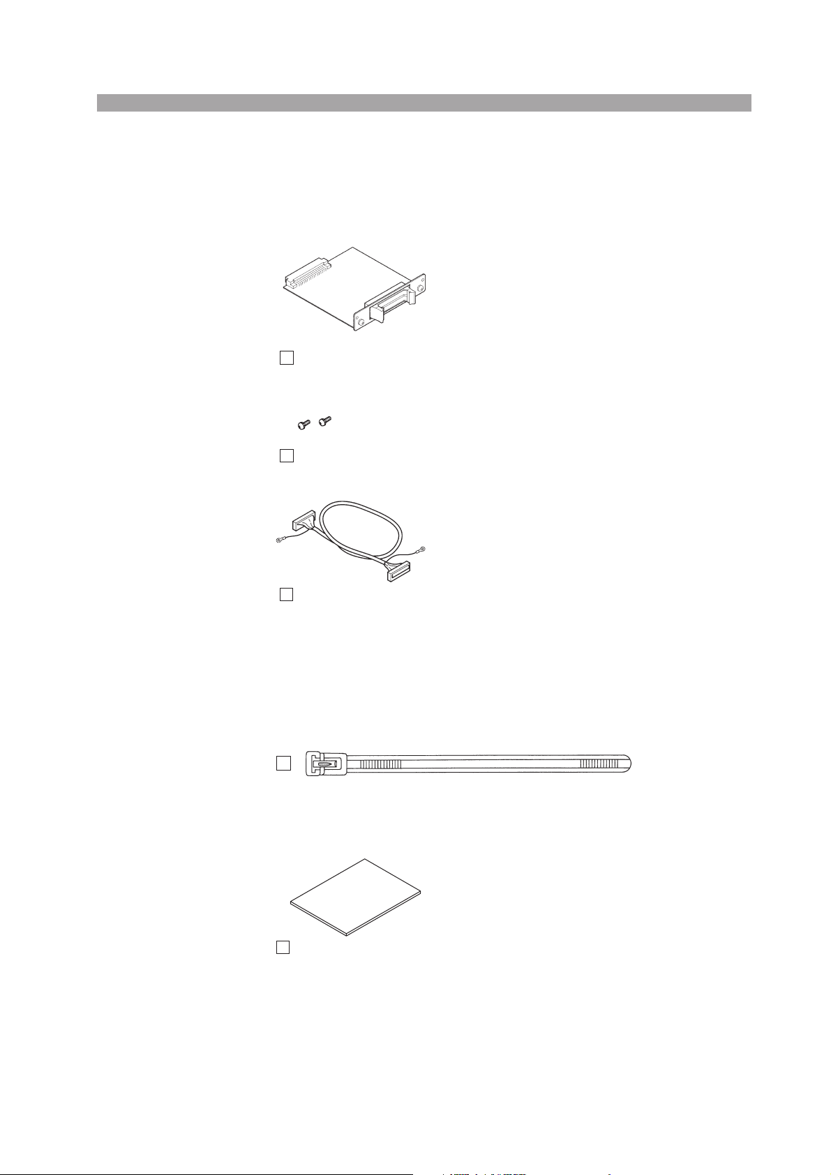
Single-phase, Three-wire Output Driver: 2P03-OT01-PCR-LA
(common to each model)
Part name Description
U-phase card
V-phase card
Drive-signal cable With drive-signal connectors (34 poles), one pc.
Mounting screw (M3) 4
*2
*2
*1
1
1
2-4 Installation and Preparation for Use OT01-PCR-LA/2
*1 These boards are dedicated for the expansion kits and are used when the PCR-LA AC
power supplies are used in combination with the Output Terminal. They cannot be
used for parallel or single-phase, three-wire operations of PCR-LA power supplies
only.
*2 The U- and V-phase cards have the indications “U” and “V” on the panel part of each
card.
The U- and V-phase cards have
the indications “U ” and “V”
on the panel part of each card.
U- and V-phase cards (one each, total of two cards)
■
M3x6
Card-mounting screws (two pcs. for each card, total of 4 pcs.)
[M3-101-001]
Drive-signal cable (34 poles, one pc., length: 0.7 m)
[91-88-4452]
Fig. 2-3 Complete Set of Single-phase, Three-wire Output Drivers
Plastic tie for signal connection cables and Operation Manual
(common to each model)
[P4-200-001]
Fig. 2-4 Plastic Tie for Signal Connection Cables, one pc.
Operation Manual, one copy
[Z1-002-892]
Fig. 2-5 Operation Manual (This Manual)
OT01-PCR-LA/2 Installation and Preparation for Use 2-5

2.2 Precautions on Installation
Be sure to observe the following precautions when installing the product.
Do not use the product in a flammable atmosphere.
To prevent explosion or fire, do not use the product near combustible materials such
as alcohol or thinner, or in an atmosphere containing such vapors.
■ Avoid locations subject to high temperatures or exposed to
direct sunlight.
Do not locate the product near a heater or in areas subject to drastic temperature
fluctuations.
Operating temperature range: 0 °C to 40 °C
■
■ Avoid humid locations.
Do not locate the product in a high-humidity location such as near a boiler, humidifier, or water supply.
Operating humidity range: 20 % to 80 % RH (no condensation allowed)
Storage humidity range: 90 % RH or less (no condensation allowed)
Condensation may occur even within the operating humidity range. In such a case,
do not start using the product until it is completely dry.
■ Do not install the product in a corrosive atmosphere.
Do not install the product in a corrosive atmosphere or one containing sulfuric-acid
mist or the like, as doing so may cause corrosion of conductors or improper connector contacts in the product, resulting in a malfunction or failure that could potentially lead to a fire.
However, modification may allow the product to cope with such an atmosphere. If
the product is to be used in such an atmosphere, consult your Kikusui distributor/
agent.
■ Do not locate the product in a dusty environment.
Dirt and dust in the product may result in electric shock or fire.
■ Do not place any object on the Output Terminal.
Heavy objects, in particular, placed on the product could lead to a malfunction.
■ Do not install the product on a tilted surface or in a location
subject to vibration.
The product may fall, resulting in damage or injury.
■ Do not use the product in locations affected by strong mag-
netic or electric fields, or where it will be exposed to waveform
distortion or noise in the input power.
Placing the product in such a location may result in a malfunction.
2-6 Installation and Preparation for Use OT01-PCR-LA/2

■ Do not use the product in locations where there is a sensitive
measuring instrument or receiver.
■ Handling of the driver cards
Always observe the following precautions when handling the driver card, as its PCB
is not protected. Otherwise, a problem may occur.
Never touch any of the electronic parts installed in the PCB.
Never handle the driver cards under conditions in which static electricity may
accumulate.
After unpacking the product carton, promptly install the driver cards in the
PCR-LA power supplies.
When storing the driver cards, always take anti-electrostatic measures such as
storing them in the bag in which they were packaged.
Do not drop the driver cards or subject them to other impact.
Do not place the driver cards where they could be exposed to water or other
liquid.
■ Handling of the drive-signal cables
Never damage the cables.
Do not pull, bend, or apply any other stress to the cables.
2.3 Moving Precautions
When moving or transporting the product to an instillation site, observe the following precautions.
■ Turn OFF the Output Terminal’s MAIN POWER switch and the
PCR-LA AC power supplies’ POWER switches.
Moving the Output Terminal or an AC power supply with the MAIN POWER or
POWER switch turned ON may result in an electric shock or breakage.
■ Disconnect all wiring connected.
Moving the Output Terminal or an AC power supply with cables connected may
cause a break in the cables or cause the respective units to fall, resulting in physical
injury.
OT01-PCR-LA/2 Installation and Preparation for Use 2-7
2.4 Grounding
The Output Terminal can be grounded by the following two methods. One of or
both of the methods can be employed to ground the Output Terminal. However, we
recommend the method in which power connection cables are employed.
1.
Use the supplied power connection cables to connect the Output Terminal to the PCR-LA AC power supplies. This enables grounding to be
provided for the Output Terminal. For the cable connection method,
“2.5.2 Connection of Power Connection Cables”.
Connecting a power connection cable to the terminals marked “G” provides
grounding for the Output Terminal.
2.
Connect the protective conductor terminal of the Output Terminal
to an electrical ground (safety ground) directly.
WARNING
• Failure to ground the Output Terminal may cause electric shock.
• There is a possibility of physical injury or death. Be sure to provide grounding.
• Connect the ground terminal to an electrical ground (safety ground).
For grounding of the PCR-LA AC power supplies, see the PCR-LA AC Power Supply Operation Manual.
2.5 Connections for a Single-phase/ Single-phase, Three-wire Switching System
Connecting cables between the Output Terminal and the two PCR-LA AC power
supplies completes the system connections. The main cabling work consists of the
following five items:
1. PCR-LA power supplies’ input power
2. Power connection cables (to the outputs of the PCR-LA power supplies)
3. Signal connection cables
4. Parallel Operation Driver
5. Single-phase, Three-wire Output Driver
Always use the cables provided with the expansion kit.
NOTE
2-8 Installation and Preparation for Use OT01-PCR-LA/2
• The Output Terminal has no input power cables. Completing the system connections allows power to be supplied to the Output Terminal.

2.5.1 Input Power of PCR-LA Power Supplies (Two Units)
WARNING
• The PCR2000LA, PCR4000LA, and PCR6000LA are permanently
installed AC power supplies. Be sure to connect these power supplies to
the switchboard.
• There is a possibility of electric shock, which could result in injury or death.
To prevent electric shock, turn OFF the switch on the switchboard (to cut
off the power feed from the switchboard) and then connect the input power
cables.
• Connection of the input power cables to the switchboard must be carried
out by a qualified personnel.
• Install the input power cable such that the distance between the PCR-LA
power supply and the switch on the switchboard is within 3 m. This procedure facilitates operation of the switch on the switchboard in the event of
emergency.
If the distance to the switch on the switchboard is to be 3 m or more, install
the input power cables with a separate switch provided within 3 m from the
Output Terminal. For such a switch, employ one of two poles that allows
both the L and N poles to be simultaneously disconnected.
Be sure to match the polarity of the input terminals with that of the switchboard (L,
N, and (GND)), and connect the cables securely. If the polarity (L, N, and ) of
the switchboard is unknown, always have it inspected by a qualified personnel or
chief electrical technician.
If the input power cables provided cannot be used due to conditions at the installation site or for any other reason, please consult with a qualified personnel or chief
electrical technician, and select the wire size (nominal conductor cross section) of
the cable to be used in accordance with the indoor wiring regulations.
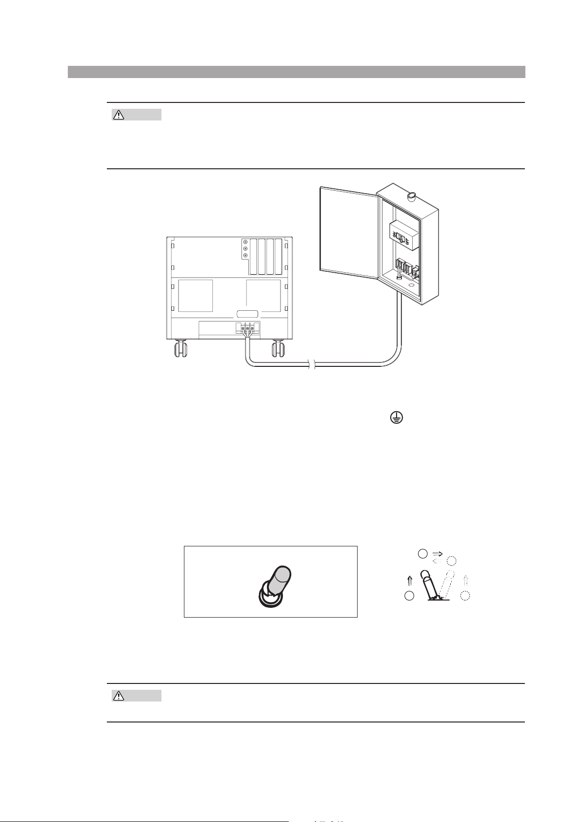
Connecting the input power cables
1. Remove the terminal-box cover from the rear of an AC power supply,
and connect the provided input power cable(s) to the INPUT terminal
board as shown in Fig. 2-6.
2.
Turn off the switch on the switchboard.
Connect the input power cable(s) to the switchboard.
3.
The switchboard ends of the input power cable(s) provided do not have terminals. For termination, attach a crimp terminal to each wire (cable) that meets
the terminal screws of the switchboard to be connected, then securely connect
the wires (cables) to the terminal screws (connection must be carried out by a
qualified personnel).
4.
Set the INPUT VOLTAGE SELECTOR to 170 V AC-250 V AC.
This system is designed especially for 200-V AC input. This step is not necessary for the PCR6000LA, as it is a power supply designed exclusively for 200V AC input.
OT01-PCR-LA/2 Installation and Preparation for Use 2-9
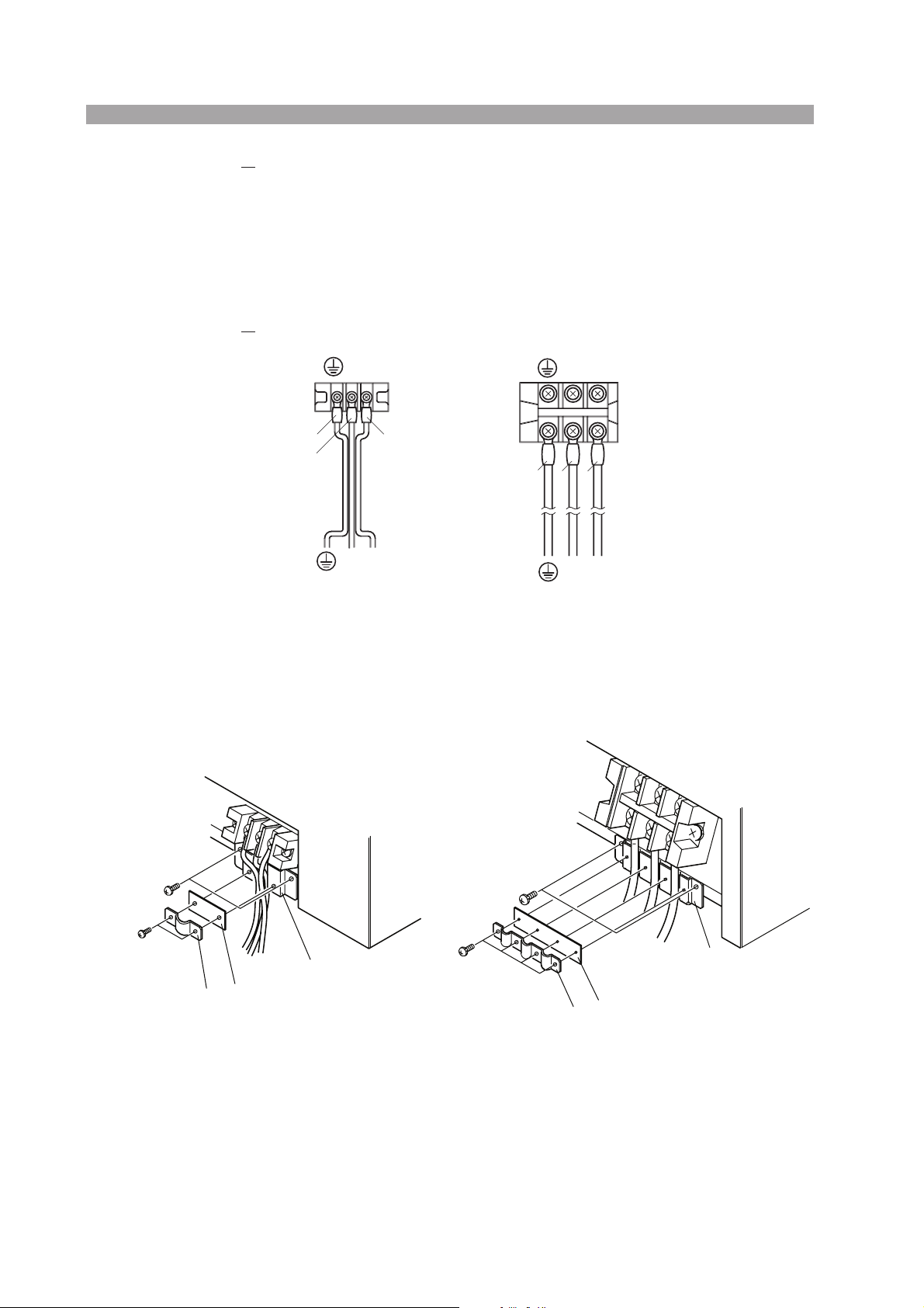
5. Install the cable clamper provided, and fix the input power cable(s)
White Black
securely (Fig. 2-7).
Using the provided M4 screws, attach part (A) to the power supply.
In this case, place the wires of the provided input power cable or the provided
input cables in the groove(s) of part (A).
Using the provided M3 screws, install parts (B) and (C) to fix the individual
wires or the cables.
6.
Put the cover removed in step 1 back on.
(GND)
Fig. 2-6 Connecting the Input Power Cable(s) to the INPUT Terminal
Cable Clampers
NL
Green
White
NL
PCR2000LA
Board
Black
NL
Green
White Black
(GND)
PCR4000LA, PCR6000LA
NL
(A)
(A)
(B)
(C)
PCR2000LA
(C)
(B)
PCR4000LA
PCR6000LA
Fig. 2-7 Installing a Cable Clamper
• For crimp terminals to be installed on the PCR-LA power supply side, always use
those matching the size of the terminal screws for the PCR-LA power supply’s
INPUT terminal board.
• For the wire sizes of the cables to be used, see the instructions in the PCR-LA AC
Power Supply Operation Manual.
2-10 Installation and Preparation for Use OT01-PCR-LA/2
CAUTION
• Improper tightening of a terminal screw may cause cable disconnection or
an overheated connection, resulting in danger.
• Never attempt to connect the input power cable(s) to the OUTPUT terminal board of a PCR-LA power supply. Otherwise, a breakdown may result.
Switchboard
INPUT
Fig. 2-8 Input Power Cable (on the Switchboard Side)
For the PCR2000LA, PCR4000LA, and PCR6000LA, connect the input power
cable(s) securely so that the symbols “L,” “N,” and (GND) on an output terminal board of the switchboard correspond to those symbols on the INPUT terminal
board of an AC power supply.
INPUT VOLTAGE SELECTOR
For the PCR2000LA and PCR4000LA, always set this selector switch to the 170 V
AC-250 V AC position.
For 170 V to 250 V input voltage
INPUT VOLTAGE SELECTOR
AC85V
~
AC132V
Fig. 2-9 INPUT VOLTAGE SELECTOR
The INPUT VOLTAGE SELECTOR is located at the center of the terminal box. It is
a lock-type toggle switch. Pull the knob to select the input voltage.
AC170V
~
AC250V
2
2
1
[Side view of the switch]
1
CAUTION
• Do not switch the INPUT VOLTAGE SELECTOR while power is fed to the
power supply. Otherwise, a malfunction may occur.
OT01-PCR-LA/2 Installation and Preparation for Use 2-11
2.5.2 Connection of Power Connection Cables
Connection of PCR-LA power supply outputs
Use the supplied power connection cables. Connect the cables from the two TO
PCR-LA OUTPUT terminals of the Output Terminal to the OUTPUT terminal
boards of the two PCR-LA AC power supplies. Be sure to confirm correspondence
of the symbols “L,” “N,” and “G” between the TO PCR-LA OUTPUT terminals and
the OUTPUT terminal boards.
OT01-PCR-LA/2 PCR-LA power supplies
CAUTION
PCR-LA-1
(MASTER)
PCR-LA-2
(SLAVE)
L1 ←→ L
N1 ←→ N
G1 ←→ G
L2 ←→ L
N2 ←→ N
G2 ←→ G
■ Cable types
5.5 mm2/2.5 m for OT01-PCR4000LA/2
2
8 mm
/2.5 m for OT01-PCR8000LA/2
14 mm
• Always use the supplied power connection cables.
2
/2.5 m for OT01-PCR12000LA/2
Master-unit OUTPUT
terminal board
Slave-unit OUTPUT
terminal board
2-12 Installation and Preparation for Use OT01-PCR-LA/2

Top rear of Output Terminal
OT01-PCR4000LA/2
Rear of the PCR2000LA
slave unit
J2J3
Rear of the PCR2000LA
master unit
J2J3
Fig. 2-10 Connection of the Power Connection Cables for
OT01-PCR4000LA/2
OT01-PCR-LA/2 Installation and Preparation for Use 2-13
 Loading...