

Kikusui 3P05-PCR-LE Setup Manual
PART NO. Z1-006-060, IA005173
Oct. 2016
Setup Guide
PCR-LE Series
Three-phase Output Driver
3P05-PCR-LE
Thank you for purchasing the PCR-LE Series Three-phase output driver.
Connecting the outputs of PCR-LE Series in star connection
and installing the Three-phase Output Driver in these power
supplies allows them to be used as three-phase system power
supplies.
Features
Use of this device allows the PCR-LE series to provide the following enhanced functions, in addition to the PCR-LE’s standard functions.
• Three-phase Output
Use of the device allows the three PCR-LE to generate three-
phase output, in which the U-phase unit of the three power
supplies acts as a master and their V and W phase units acts
as slaves.
• Setting of Either the Line Voltage or Phase Voltage
• Independent Phase Voltage Setting
The individual phase voltage setting is possible on a phase
basis.
• Line Voltage Measurement
• Measurements of the Total Power, Total Apparent Power, and
Total Power Factor of Three Phases
Use of the device allows the totals of power and apparent
power obtained through measurement using the three PCRLE to be displayed. The total power factor of the three phases can also be calculated from these total values.
• Variable Phase Difference
KIKUSUI ELECTRONICS CORP.
1-1-3, Higashiyamata, Tsuzuki-ku, Yokohama, 224-0023, Japan
TEL: +81-45-593-7570 Fax: +81-45-593-7571
WEBSITE
http://www.kikusui.co.jp/en
PCR-LE Manual
Check at Unpacking
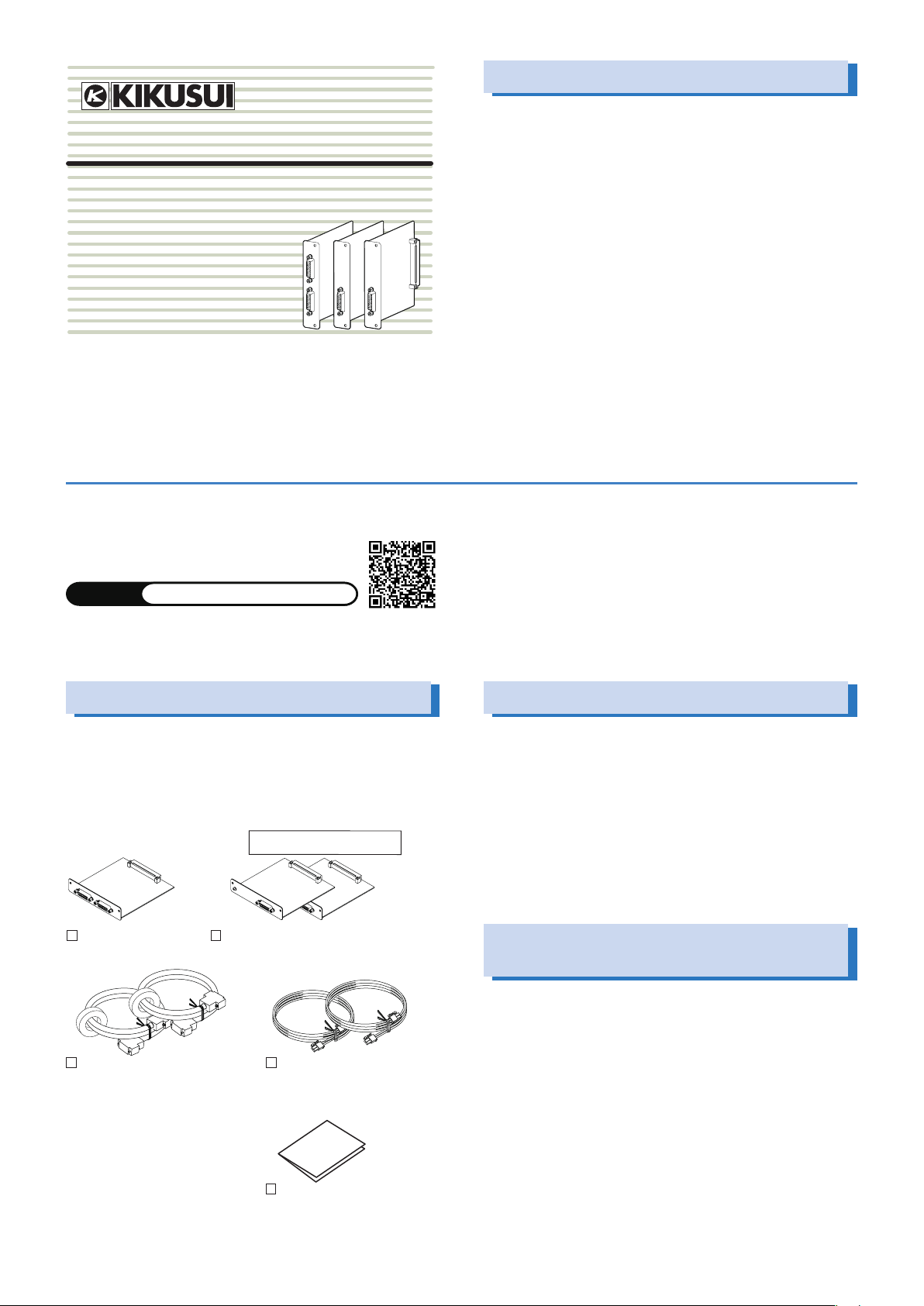
Upon reception of the product, confirm that the package contains the necessary accessories and that the device and accessories have not been damaged during transportation. If the
device is damaged or any accessory is missing, notify Kikusui
distributor/agent.
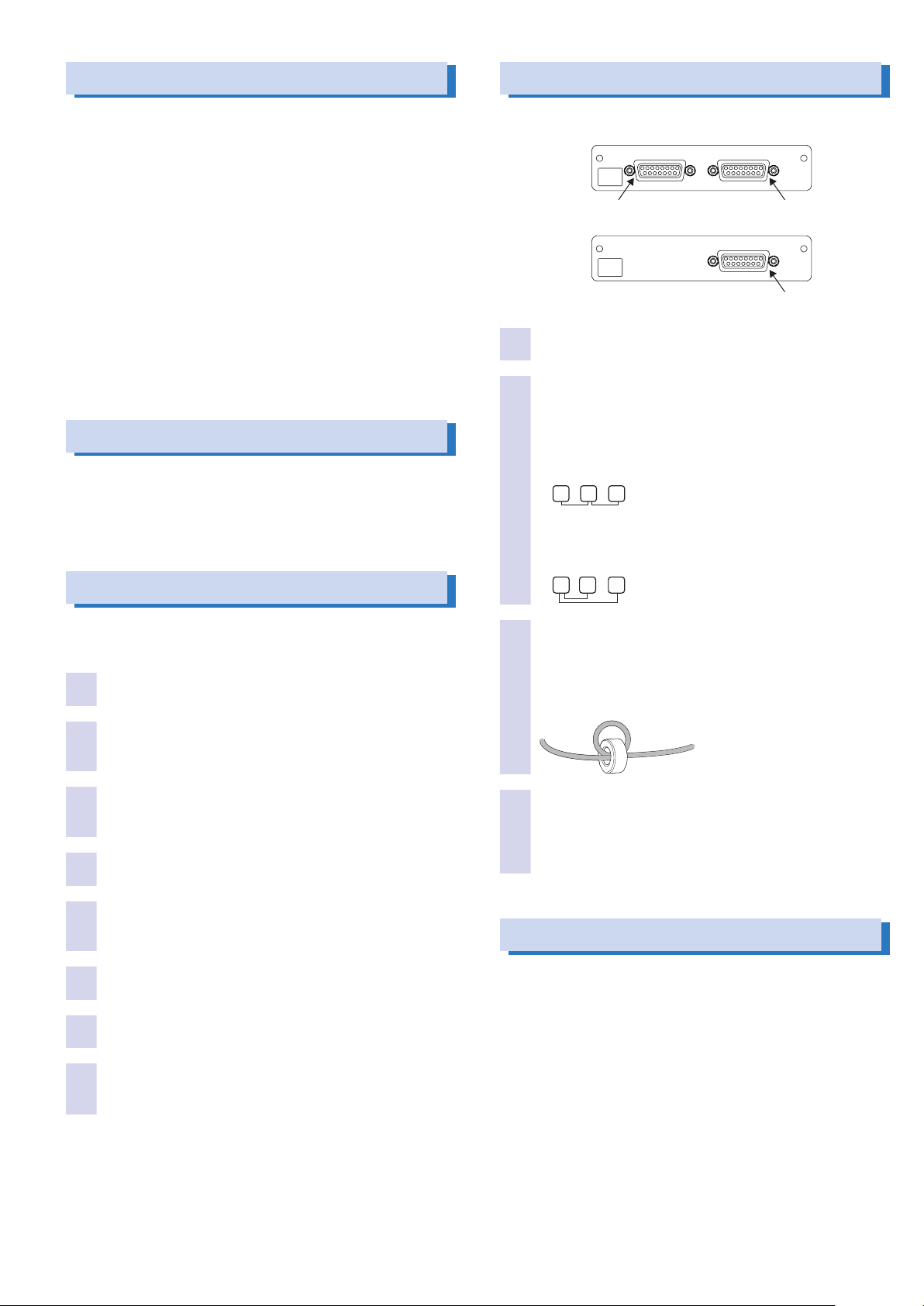
The indications “V” and “W” on the
panel part of each board.
U phase boards
(1 pc.)
V and W phase boards
(one each)
The 3P05-PCR-LE is subject to export control laws.
The newest version of the operation manual can be downloaded from
Download service of Kikusui website.
The contents of this manual may not be reproduced, in whole or in part,
without the prior consent of the copyright holder.
The specifications of this product and the contents of this manual are
subject to change without prior notice.
© 2012
Firmware version of PCR-LE
When using the 3P05-PCR-LE, the PCR-LE must be required
with the firmware version of 2.00 or later. If the firmware version of the PCR-LE is 1.99 or previous version, the PCR-LE is
required for the firmware update.
When using the 3P05-PCR-LE, the firmware of all the PCR-LE
series that make up the system must be the same.
To check the firmware version of the PCR-LE, refer to the operation manual of the PCR-LE series. In case, the PCR-LE needs
update, contact your Kikusui agent or distributor.
Functional Restrictions during
Three-phase Operation
Use of the 3P05-PCR-LE allows the PCR-LE series to generate
three-phase outputs. The following functions are not available
when the device is installed in the power supplies.
Connecting cable (75 cm; 2 pcs.)
Cable: [91-80-9919]
Core: [96-00-0530]
3P05-PCR-LE 1
Power-sync cable
(1 m; 2 pcs.)
[91-80-5099]
Setup Guide
(This guide)(1 pc.)
DC mode
Regulation adjustment
High-speed response
You cannot use the 3P05-PCR-LE with the 2P05-PCR-LE SinglePhase Three-Wire Output Driver Option.
Handling Precautions
V U W
U V W
Connecting the bords
Handling of the U, V, and W phase Boards
• Ground yourself by touching a grounded metal object before
touching the board.
• Avoid handling the interface board in an environment subject to
strong static electricity.
• For storage, provide electrostatic protection measures such as
the anti-static bag accompanying the interface board.
• Do not drop a board or subject it to other impact.
• Do not install or uninstall the interface board with the power ON
of the PCR-LE Series.
Handling of the connecting and power-sync cable
• Do not damage the cable.
• Do not pull, bend, or apply any other stress to the cable.
Precautions When Moving the PCR-LE
Disconnect the cable(s) when moving the PCR-LE series to the
installation location or when transporting the PCR-LE. Moving a
PCR-LE series with a cable connected to the phase board may
result in breakage of the cable or connector.
Use the connecting cable to connect the boards.
3
U-phase board
Connect the V-phase
V-Phase board/
W-phase board
Check that the POWER switch of PCR-LE is off.
1
Place the three PCR-LE as close to each other as
2
possible.
Arrange them so that no stress is applied to the connecting cable. A PCR-LE power supply with the U phase board
installed plays the role of the master unit that controls other
power supplies.
For the connection as shown below, you need the optional
connecting cable (150 cm/ 280 cm). To perform parallel threephase operation, place the U phase to the center.
PHASE DRIVER
TO V PHASE TO V PHASE
3
PHASE DRIVER
-
3P05
PCR-LE
Connect the W-phase
-
3P05
PCR-LE
FROM U PHASE
Connect the U-phase
Installing the board on the PCR-LE
The 3P05-PCR-LE can be installed by inserting the U, V, and W
phase boards into SLOT1 of the three PCR-LE series, respectively.
Check that the POWER switch of PCR-LE is off.
1
Touch a grounded metal object (for example, the
2
metal parts of the PCR-LE rear panel) to discharge
any static electricity from your body.
Remove the screws that are holding the SLOT 1
3
cover in place on the rear panel, and remove the
cover from the panel.
Hold the panel parts of the board so that the printed
4
circuit board side is facing up.
Insert the board into the slot so that the printed cir-
5
cuit board's connector is inserted into the connector at the back of the slot.
Insert the board all the way into the slot.
6
Use the screws that you removed in step 3 to x the
7
board in place in the panel.
Follow the same procedure to install the other two
8
boards.
This completes installation of the phase board.
When a 3P05-PCR-LE has been inserted into the slot1 of a PCRLE series, that power supply can be used only in a three-phase
system. To use the power supply in a single-phase system, the
phase board must be removed from the slot1.
Connect the “TO V PHASE“ of U-phase unit and the
3
“FROM U PHASE“ of V-phase unit firmly with the
connecting cable using a screwdriver.
Do not remove the attached core from the cable. If you do,
reattach it (be sure to wrap the cable around the core once (2
turns)).
Follow the same procedure to connect the “TO W
4
PHASE“ of U-phase unit and the “FROM U PHASE“
of W-phase unit with the connecting cable.
Do not remove the attached core from the cable.
This completes connection of the bords.
Operation Check
Check the operation of the PCR-LE series before you perform
three-phase operation.
Check the following items with no load connected. For detail of
settings, see the PCR-LE series operation manual.
POWER switch ON
Voltage setting
OUTPUT ON/OFF
Voltage-range switching
If a trouble is occurring on even one unit, you will not be able to
perform three-phase operation.
2 3P05-PCR-LE
 Loading...