

Page 1
Operating instructions
5093 xxx 000-xxx
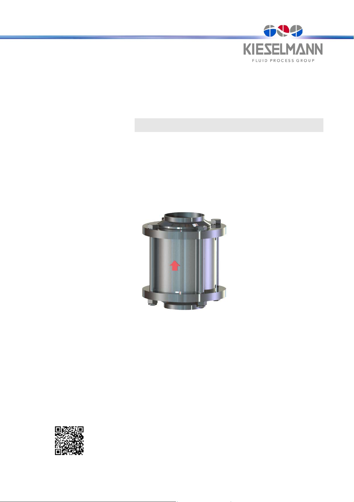
Check valve
DN 25 - DN 100
OD 1inch - OD 4inch
EPDM O-Ring-design
Intermediate flanged with welding ends
- Translation of the original -
19.2.16
English
GBR
KIESELMANN GmbH
Paul-Kieselmann-Str.4-10
D - 75438 Knittlingen
+49 (0) 7043 371-0Fax: +49 (0) 7043 371-125
www.kieselmann.desales@kieselmann.de
1
Page 2

1. List of contents
1. List of contents ..............................................................................................................................1
2. General Information......................................................................................................................2
3. Safety instructions .........................................................................................................................3
4. Function.........................................................................................................................................3
5. Installation informations.................................................................................................................3
6. Maintenance..................................................................................................................................4
2.1 Information for your safety .................................................................................................2
2.2 Marking of security instructions in the operating manual ...................................................2
2.3 Designated use ..................................................................................................................2
2.4 Personnel...........................................................................................................................2
2.5 Modifications, spare parts, accessories .............................................................................2
2.6 General instructions ...........................................................................................................2
3.1 Field of application .............................................................................................................3
3.2 General safety instructions ................................................................................................3
3.3 General notes ....................................................................................................................3
4.1 Description of function .......................................................................................................3
5.1 Installation instructions.......................................................................................................3
5.2 Welding guidelines.............................................................................................................3
6.1 Maintenance ......................................................................................................................4
6.2 Cleaning.............................................................................................................................4
7. Technical Data ..............................................................................................................................4
8. Disassembly and assembly...........................................................................................................5
8.1 Disassembly.......................................................................................................................5
8.2 Assembly ...........................................................................................................................5
9. Drawings .......................................................................................................................................5
10. Dimensions....................................................................................................................................6
11. Wearing parts ................................................................................................................................6
12. Valve size ......................................................................................................................................6
19.2.16
Check valve Type: 5093xxx000-xxx
1
Page 3
2. General Information
2.1 Information for your safety
We are pleased that you have decided for a high-class KIESELMANN product. With correct application
and adequate maintenance, our products provide long time and reliable operation.
Before installation and initiation, please carefully read this instruction manual and the security advices
contained in it. This guarantees reliable and safe operation of this product and your plant respectively.
Please note that an incorrect application of the process components may lead to great material damages and personal injury.
In case of damages caused by non observance of this instruction manual, incorrect initiation,
handling or external interference, guarantee and warranty will lapse!
Our products are produced, mounted and tested with high diligence. However, if there is still a reason
for complaint, we will naturally try to give you entire satisfaction within the scope of our warranty. We
will be at your disposal also after expiration of the warranty. In addition, you will also find all necessary
instructions and spare part data for maintenance in this instruction manual. If you don't want to carry
out the maintenance by yourself, our KIESELMANN service team will naturally be at your disposal.
2.2 Marking of security instructions in the operating manual
Hints are available in the chapter "safety instructions" or directly before the respective operation
instruction. The hints are highlighted with a danger symbol and a signal word. Texts beside these symbols have to be read and adhered to by all means. Please continue with the text and with the handling
at the valve only afterwards.
Symbol Signal word Meaning
Imminent danger which may cause severe
personal injury or death.
DANGER
Dangerous situation which may cause slight
personal injury or material damages.
Marks application hints and other information which is particularly useful.
ATTENTION
NOTE
2.3 Designated use
The fitting is designed exclusively for the purposes described below. Using the fitting for purposes
other than those mentioned is considered contrary to its designated use. KIESELMANN cannot be held
liable for any damage resulting from such use. The risk of such misuse lies entirely with the user. The
prerequisite for the reliable and safe operation of the fitting is proper transportation and storage as well
as competent installation and assembly.
Operating the fitting within the limits of its designated use also involves observing the operating, inspection and maintenance instructions.
2.4 Personnel
Personnel entrusted with the operation and maintenance of the tank safety system must have the suitable qualification to carry out their tasks. They must be informed about possible dangers and must
understand and observe the safety instructions given in the relevant manual. Only allow qualified personnel to make electrical connections.
2.5 Modifications, spare parts, accessories
Unauthorized modifications, additions or conversions which affect the safety of the fitting are not permitted. Safety devices must not be bypassed, removed or made inactive. Only use original spare parts
and accessories recommended by the manufacturer.
2.6 General instructions
The user is obliged to operate the fitting only when it is in good working order. In addition to the instructions given in the operating manual, please observe the following:
• relevant accident prevention regulations
• generally accepted safety regulations
• regulations effective in the country of installation
• working and safety instructions effective in the user's plant.
General Information
2
Page 4

3. Safety instructions
3.1 Field of application
The check valve is suitable for use as a reflux - check valve for gas and fluid in plants in the food and
beverage, in pharmaceutical, biotechnological and chemical industries.
ATTENTION
• To avoid danger and damage, the fitting must be used in accordance with the safety instructions and technical
data contained in the operating instructions.
3.2 General safety instructions
DANGER
• Dismantling the valve or valve assemblies from the plant can cause injuries from fluids or gases flowing out.
Dismantle the valve or valve assembly only when the plant has been rendered pressure-less and
free of liquid and gas.
3.3 General notes
NOTE
All data are in line with the current state of development. Subject to change as a result of technical
progress.
4. Function
4.1 Description of function
The valve open against spring power with flow pressure > X bar in flow direction “A“ (see Tab.).
The valve close added by spring power with flow pressure > 0,1 bar in flow direction “B“.
Flow pressure*
NOTE
A pressure from min 0,8 bar is necessary for a leakproof shut off in flow direction "B".
5. Installation informations
5.1 Installation instructions
Fitting position
Check valve be installed preferably vertically, with the flow direction from bottom to top.
5.2 Welding guidelines
Sealing elements integrated in weld components must generally be removed prior to welding. To prevent
damage, welding should be undertaken by certified personnel (EN287). Use the TIG (tungsten inert gas)
welding process.
NOTE
Impurities can cause damage to the seals.
Clean inside areas prior to assembly.
DIN
INCH
Nominal Diameter DN / OD
25
1“
0,11 0,09 0,14 0,15 0,16 0,15 0,07
32
-
*) measured in installation position and flow direction from bottom to top
40
1½“
50
2“
65
2½“
80
3“
100
4“
ak 12.1.11
Check valve Type: 5093xxx000-xxx
3
Page 5

6. Maintenance
6.1 Maintenance
The maintenance intervals depend on the operating conditions "temperature, temperature-intervals,
medium, cleaning medium, pressure and opening frequency". We recommend replacing the seals every
1 years. The user, however should establish appropriate maintenance intervals according to the con dition
of the seals.
6.2 Cleaning
The cleaning of the valve takes place during the pipe cleaning.
7. Technical Data
NOTE
Lubricant recommendation
EPDM; Viton; K-flex; NBR; HNBR
Silicone
Thread
*) It is only permitted to use approved lubricants, if the respective fitting is used for the production of food or drink. Please observe the rel-
evant safety data sheets of the manufacturers of lubricants.
Valve size: DIN: DN 25 - DN 100
Connections: Intermediate flanged with welding end DIN11850
INCH: OD 1inch - OD 4inch
Klüber Paraliq GTE703*
Klüber Sintheso pro AA2*
Interflon Food*
Temperature range: • Product temperature: +0° to +95°C medium-dependent
Operating pressure: DN 25 - DN 65
Vacuum: 1,5 - 10-6 mbar x L/S
Material in product contact: Stainless steel: • 1.4301 / AISI304
DIN
INCH
25
1“
• Sterilization temperature: EPDM +140°C (SIP 30 min)
OD 1“ - OD 2½“ = 16 bar
DN 80 - DN 100
OD 3“ - OD 4“ = 10 bar
(test pressure 0,5mbar)
• 1.4404 / AISI316L
Surfaces: • Ra < 0,8µm e-polished
Seal material: • EPDM (FDA)
Nominal diameter DN / OD
32
-
40
1½“
• k-flex (FDA)
50
2“
65
2½“
80
3“
100
4“
ak 12.1.11
KV-value (m³/h)
18 28,5 36 60 104 150 230
Check valve Type: 5093xxx000-xxx
4
Page 6

8. Disassembly and assembly
8.1 Disassembly
see Fig. 1 /page 5
• Unscrew the nuts (8).
• Remove axially the screws / threat bolts (9).
• Dismantle housing (11) and cramp it axially in a vise.
• Unscrew the headless pin (10).
NOTE
The tightly seats (3) sit close by feather tension to the vise chop. Open the vise and the spring is thereby
relaxed.
• Unscrew the union nuts at both ends and dismantle valve.
• Take all parts out of out of the housing (11).
Dismantle the
•
O-Rings (4) and (7).
8.2 Assembly
• Thoroughly clean and slightly lubricate mounting areas and running surfaces. (see “6.1 Maintenance” on page 4).
• Assemble in reverse order.
NOTE
In part by alternating sides, push and roll the O-Ring (7) into the groove with a round component.
• Check the valve function.
9. Drawings
1) Flange
2) Seal
3) Tightly seat
4) O-Ring
5) Guidance
6) Pressure spring
7) O-Ring
8) Hexagon nut
self-locking
9) Screw / Threat bolt
10) Headless pin
11) Housing
12) Plate
DN25 - 80 DN100
ak 12.1.11
Fig. 1
Check valve Type: 5093xxx000-xxx
5
Page 7

10. Dimensions
DN / OD D1 D2 L X
25 29x1,5 80 104 50
32 35x1,5 86 104 51
40 41x1,5 92 113 59
50 53x1,5 108 119 71
65 70x2 130 127 79
80 85x2 146 145 96
100 104x2 166 159 111
1 INCH 25,4x1,65 80 104 50
1½ INCH 38,1x1,65 92 113 59
2 INCH 50,8x1,65 108 119 71
2½ INCH 63,5x1,65 130 127 79
3 INCH 76,1x2,00 146 145 96
4 INCH 101,6x2,00 166 159 111
11. Wearing parts
Seal kit - EPDM
DN / OD
DIN
INCH
25
1‘‘
32
-
40
1½‘‘
50
2‘‘
65
2½‘‘
80
3‘‘
100
4‘‘
(incl. Pos. 2,4,6,7)
5095 025 029-054
5095 026 029-054
5095 032 029-054
5095 040 029-054
5095 038 029-054
5095 050 029-054
5095 051 029-054
5095 065 029-054
5095 064 029-054
5095 080 029-054
5095 076 029-054
5095 100 029-054
5095 101 029-054
Seal kit
O-Ring-type
EPDM
-
O-Ring - type:
Gasket seal - type:
Pos. 2 Pos. 4 Pos. 6 Pos. 7 Pos. X
Seal
k-flex
2353 035 026-114
2353 032 024-114
2353 041 032-114
-
2353 047 038-114
2353 044 036-114
2353 059 050-114
2353 057 049-114
2353 076 066-114
2353 071 061-114
2353 090 081-114
2353 083 073-114
2353 109 100-114
2353 107 099-114
2304 031 035-159 8150 117 060-031 2304 020 030-170 2355 027 004-054
2304 041 035-159 8150 117 060-031 2304 024 035-170 2355 032 004-054
2304 047 025-159 8150 181 000-031 2304 028 035-170 2355 028 005-054
2304 062 035-159 8150 182 000-031 2304 041 035-170 2355 049 005-054
2304 085 040-170 8150 209 000-031 2304 057 035-170 2355 066 005-054
2304 100 040-159 8150 236 000-031 2304 069 035-170 2355 079 005-054
2304 118 045-170 8150 236 000-031 2304 088 035-170 2355 103 008-054
5095 DN 029-054 (incl. Pos. 2, 4, 6, 7)
5095 DN 000-054 (incl. Pos. 2, 4, 6, X)
O-Ring
EPDM
Spring Valve plate
O-Ring
EPDM
Fig. 2
Valve plate
Gasket seal EPDM
(design up to 09/2010)
12. Valve size
ak 12.1.11
DIN
INCH
025
026
= DN25
= OD 1“
040
038
= DN40
= OD 1½“
050
051
= DN50
= OD 2“
065
= DN65
064
= OD 2½“§
DN / OD = Nominal diameter = e.g. 5093 051 000-041
080
076
= DN80
= OD 3“
Check valve Type: 5093xxx000-xxx
100
101
= DN100
= OD 4“
6
 Loading...