

KIESELMANN 402 Series, 422 Series, 412 Series, 406 Series, 416 Series Operating Instruction
...Page 1
Translation of the original
Operating instruction
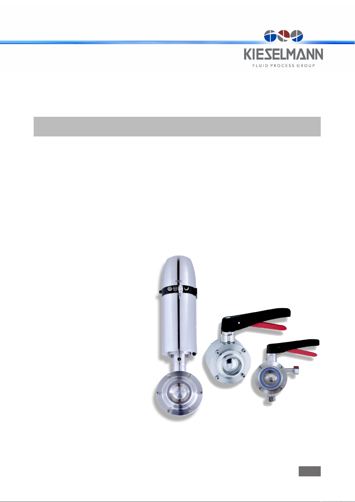
Straight-way ball valve
pneumatic und manual operation
Types 402x
412x
422x
P DF • a k • 1 8 /0 7/ 20 19
ENGLISH
GB
Page 2

K I E S E L M A N N G m b H
Pa u l- Ki e se l ma nn - St r . 4- 1 0
75 4 38 K n it t li ng e n
( + 49 ( 0 ) 7 0 43 3 7 1- 0 • 7 +4 9 (0 ) 7 04 3 3 7 1 - 12 5
ww w .k ie s el m an n. d e • i nf o @k i es el m an n . d e
Copyright: © KIESELMANN FLUID PROCESS GROUP
Page 3

KIESELMANN GmbH Table of contents
Ta ble of c o nte n ts
1 General informations ....................................................................................................................................................4
1.1 Informations for your safety ............................................................................................................................................... 4
1.2 Marking of security instructions......................................................................................................................................... 4
1.3 General designated use ......................................................................................................................................................4
1.4 Personnel ............................................................................................................................................................................. 4
1.5 Modifications, spare parts, accessories ............................................................................................................................ 5
1.6 General instructions ............................................................................................................................................................5
2 Safety instructions........................................................................................................................................................6
2.1 Intended use ........................................................................................................................................................................6
2.2 General notes....................................................................................................................................................................... 6
2.3 General safety instructions.................................................................................................................................................6
3 Delivery, transport and storage .....................................................................................................................................8
3.1 Delivery................................................................................................................................................................................. 8
3.2 Transport..............................................................................................................................................................................8
3.3 Storage.................................................................................................................................................................................8
4 Specification.................................................................................................................................................................9
4.1 Modular system...................................................................................................................................................................9
5 Function and operation ...............................................................................................................................................10
5.1 Description of function......................................................................................................................................................10
5.2 Control system and position indication ...........................................................................................................................11
6 Commissioning, service and maintenance ..................................................................................................................12
6.1 Commissioning..................................................................................................................................................................12
6.1.1 Installation instructions....................................................................................................................................... 12
6.1.2 General welding guidelines ................................................................................................................................. 12
6.1.3 ATEX - Guidelines ................................................................................................................................................ 12
6.2 Service................................................................................................................................................................................13
6.3 Cleaning .............................................................................................................................................................................13
7 Technical data ............................................................................................................................................................14
8 Disassembly and assembly .........................................................................................................................................15
8.1 Disassembly.......................................................................................................................................................................15
8.2 Assembly ...........................................................................................................................................................................16
9 Drawings and dimensions ...........................................................................................................................................17
9.1 Control units ......................................................................................................................................................................17
9.2 Drawings ............................................................................................................................................................................18
9.3 Dimensions ........................................................................................................................................................................19
10 Wearing parts .............................................................................................................................................................20
10.1 Wear parts kit.....................................................................................................................................................................20
10.2 Spare parts list...................................................................................................................................................................21
11 Classification..............................................................................................................................................................22
11.1 Structure of Order Number ...............................................................................................................................................22
12 Appendix ....................................................................................................................................................................24
12.1 Declaration of incorporation.............................................................................................................................................24
4x2x_SWBV_EN III
Page 4
Operating instruction | KIESELMANN GmbH1 | General informations
1 Gener a l i n for m ati o ns
1.1 Informations for your safety
We are pleased that you have decided for a high-class KIESELMANN GmbH product. With correct
application and adequate maintenance, our products provide long time and reliable operation.
Before installation and initiation, please carefully read this instruction manual and the security advices contained in it. This guarantees reliable and safe operation of this product and your plant respectively. Please note that an incorrect application of the process components may lead to great
material damages and personal injury.
In case of damages caused by non observance of this instruction manual, incorrect initiation, handling or external interference, guarantee and warranty will lapse!
Our products are produced, mounted and tested with high diligence. However, if there is still a
reason for complaint, we will naturally try to give you entire satisfaction within the scope of our warranty. We will be at your disposal also after expiration of the warranty. In addition, you will also find
all necessary instructions and spare part data for maintenance in this instruction manual. If you
don't want to carry out the maintenance by yourself, our KIESELMANN GmbH - service team will
naturally be at your disposal.
1.2 Marking of security instructions
Hints are available in the chapter "safety instructions" or directly before the respective operation instruction. The hints are highlighted with a danger symbol and a signal word. Texts beside these
symbols have to be read and adhered to by all means. Please continue with the text and with the
handling at the valve only afterwards.
Symbol Signal word Meaning
DANGER Imminent danger which will result severe personal injury or
death.
WARNING Imminent danger which may result severe personal injury or
death.
CAUTION Dangerous situation which may cause slight personal injury or
material damages.
NOTICE An harmful situation which may result in damages of the product
itself or of adjacent vicinity.
INFORMATION Marks application hints and other information which is particu-
larly useful.
1.3 General designated use
The fitting is designed exclusively for the purposes described below. Using the fitting for purposes
other than those mentioned is considered contrary to its designated use. KIESELMANN GmbH cannot be held liable for any damage resulting from such use. The risk of such misuse lies entirely with
the user. The prerequisite for the reliable and safe operation of the fitting is proper transportation
and storage as well as competent installation and assembly. Operating the fitting within the limits
of its designated use also involves observing the operating, inspection and maintenance instructions.
1.4 Personnel
Personnel entrusted with the operation and maintenance of the tank safety system must have the
suitable qualification to carry out their tasks. They must be informed about possible dangers and
must understand and observe the safety instructions given in the relevant manual. Only allow qualified personnel to make electrical connections.
4 / 24 4x2x_SWBV_EN
Page 5

KIESELMANN GmbH | Operating instruction General informations | 1
1.5 Modifications, spare parts, accessories
Unauthorized modifications, additions or conversions which affect the safety of the fitting are not
permitted. Safety devices must not be bypassed, removed or made inactive. Only use original spare
parts and accessories recommended by the manufacturer.
1.6 General instructions
The user is obliged to operate the fitting only when it is in good working order. In addition to the instructions given in the operating manual, please observe the relevant accident prevention regulations, generally accepted safety regulations, regulations effective in the country of installation,
working and safety instructions effective in the user's plant.
4x2x_SWBV_EN 5 / 24
Page 6
Operating instruction | KIESELMANN GmbH2 | Safety instructions
2 Safet y in s tru c tio n s
2.1 Intended use
Straight-way ball cocks are used as a shut-off valve in units of the beverage and food industry, the
pharmacy, the biotechnology as well as the chemical industry.
2.2 General notes
NOTICE - observe the operating instructions
To avoid danger and damage, the fitting must be used in accordance with the safety instructions
and technical data contained in the operating instructions.
NOTICE
All data are in line with the current state of development. Subject to change as a result of technical progress.
2.3 General safety instructions
WARNING
Risk of injury by outflowing medium
Dismantling the valve or valve assemblies from the plant can cause injuries.
– Medias flowing through the leakage drain outlet are to be drained off without splashing
into a discharge arrangement.
– Carry the disassembling only if when the plant has been rendered pressure-less and free
of liquid and gas.
WARNING
Risk of injury by moving parts
Do not grab into the valve when the actuator is pressurized. Limbs can be crushing or amputating.
– Remove the control air line before dismantling.
– Ensure that the actuator is unpressurized.
WARNING
Risk of injury by pre-stressed pressure spring.
The pneumatic-mechanical actuator is spring-loaded. When disassembling the actuator, components that jump out may cause injuries.
– Multiturn actuator are maintenance-free and therefore do not need to be opened!
WARNING
ATEX - Guidelines
If the valve or the plant is operated in a potentially explosive atmosphere, the valid ATEX directive of
the EC and the installation instructions in this operating manual must be observed.
CAUTION
To avoid air leaking, only use pneumatic connection parts that have an O-ring seal facing the even
surface.
6 / 24 4x2x_SWBV_EN
Page 7

KIESELMANN GmbH | Operating instruction Safety instructions | 2
CAUTION
Before starting the system, the entire pipeline system must be thoroughly cleaned.
CAUTION
Steps should be taken to ensure that no external forces are exerted on the fitting.
4x2x_SWBV_EN 7 / 24
Page 8
Operating instruction | KIESELMANN GmbH3 | Delivery, transport and storage
3 Deliv e ry, tra n spo r t a n d s t ora g e
3.1 Delivery
• Immediately after receipt check the delivery for completeness and transport damages.
• Remove the packaging from the product.
• Retain packaging material, or expose of according to local regulations.
3.2 Transport
CAUTION
Risk of injury and damage to the product
During the transport the generally acknowledged rules of technology, the national accident prevention regulationsand company internal work and safety regulations must be observed.
3.3 Storage
NOTICE
Damage to the product due to improper storage!
Observe storage instructions
avoid a prolonged storage
INFORMATION
Recommendation for longer storage
We recommend regularly checking the product and the prevailing storage conditions during long
storage times.
• To avoid damage to seals and bearings,
– products up to DN 125 / OD 5 inch should be stored horizontally for maximum 6 months.
– products larger than DN 125 / 5 inch, should be stored in the upright position with the actu-
ator on top.
• Don't store any objects on the products.
• Protect the products for wetness, dust and dirt.
• The product should be stored in a dry and well ventilated room at a constant temperature (optimal indoor temperature: 25 C ±5; indoor humidity data 70% ±5%).
• Protect seals, bearings and plastic parts for UV light and ozone.
8 / 24 4x2x_SWBV_EN
Page 9

KIESELMANN GmbH | Operating instruction Specification | 4
4 Speci f ica t ion
4.1 Modular system
KI-Top control head Feedback unit
Stainless steel hood: Transparent hood
drive systems
pneumatical electrical
PDA 90/75
Ø 75
PDA 90/100
Ø 100
PDA 90/125
Ø 125
4040
manual
Hand lever Hand lever
with sensor mounting
Model
Standard
PTFE - Thrust collar
Seal material
connection flanges
S G K/M Fl Cl
Hand lever
stainless steel
Filling element
Hand lever
continuously adjustable
PTFE - shell
EPDM
NBR
FKM
VMQ
4x2x_SWBV_EN 9 / 24
Page 10

Operating instruction | KIESELMANN GmbH5 | Function and operation
A B A B
90°
5 Funct i on a nd o per a tio n
5.1 Description of function
Straight-way ball cocks are used as a piggable shut-off valve.
Open or close the valve by turning the pneum. controlled rotary drive by 90°.
Functional description for valves with manual operation
When actuating a fitting manually, the respective switching position will be locked in place in the final position. The manually operated lever is positioned at an angle of 90°in transverse direction to
the conduit axis in closed position The lever is positioned in the direction of the conduit axis in
open position.
Before operation, unlock the final position lock by lifting the notch lever against the hand lever. By
letting go of the notch lever in the respective final position the spring-loaded notch lever will latch
back by itself to the final position lock. The position of the hand lever indicates whether the valve is
opened or closed. It will be opened, if the valve points in the direction of the pipe axle – it will be
closed, if the valve is positioned crosswise to the pipe axle. The possible assembly-line ways in dependence of the stop functions linked with it are shown in the as valve positions.
Valve positions
Valve position 1
Connection A - B open
Valve position 2
Connection A - B closed
Description of function for pneum. valves
The valve opens and closes by way of a pneum. multiturn actuator with a rotary movement of 90°.
normal closed (NC)
• pneum. OPERATED
• not pneum. OPERATED
normal open (NO)
• pneum. OPERATED
• not pneum. OPERATED
double acting (DA)
• pneum. OPERATED the valve opens or closes according to control
opens the valve
spring force closes the valve
closes the valve
spring force opens the valve
10 / 24 4x2x_SWBV_EN
Page 11

KIESELMANN GmbH | Operating instruction Function and operation | 5
5.2 Control system and position indication
Retrofitting to end position feedback for manually operated valves
By replacing the hand lever and the catch disc the valve can be retrofitted for end position feedback
(proximity switch).
Conversion from manual operation to pneumatic actuation
By a simple retrofitting operation the valve can be converted to pneumatic actuation. The rotary actuator for this purpose is supplied complete with fitting device. The following actuators are available, depending on the desired actuating function.
Nominal diameter
DN25 - DN80
1“ - 3“
DN 100
DN 4“
Pneum. actu-
ator
PDA 90/100 4100 080 100-022 4200 080 100-022
PDA 90/125 4100 100 125-022 4200 100 125-022
air open - air close (DA) Normally closed (NC)
Position indicator with sensor mounting for feedback signal.
The actuator is equipped with a proximity switch mounting (sensor mounting) and a position indication. When inductive proximity initiators M 12x1 are installed, the current "Open" or "Shut" position
can be interrogated. By screwing the proximity initiator to the limit position the required switching
gap for the signal transmission is established.. When the valve is closed the position indication is
oriented vertically to the direction of valve passage. When the valve is open it is oriented parallel to
the valve passage.
Feedback unit -optional-
Optionally, modular valve control head systems can be installed to the actuator for reading and actuating valve positions. The standard version is a closed system with SPS or ASI-bus switch-on
electronics, and integrated 3/2-way solenoid valves. For tough operating conditions we recommend
employing a high-grade steel cover.
4x2x_SWBV_EN 11 / 24
Page 12

Operating instruction | KIESELMANN GmbH6 | Commissioning, service and maintenance
6 Commi s sio n ing , se r vic e an d ma i nte n anc e
6.1 Commissioning
6.1.1 Installation instructions
For ball valves without leakage outlet, the installation position is without importance.
Ball valves with leakage outlet must always be installed vertically to ensure that outflow of leakage,
or of cleaning medium, from the valve is such that no residue will remain inside the valve.
For valves which are to be welded in on both sides, a releasable connection has to be fitted into the
pipework to allow dismounting (maintenance).
6.1.2 General welding guidelines
Sealing elements integrated in weld components must generally be removed prior to welding. To
prevent damage, welding should be undertaken by certified personnel (EN ISO 9606-1). Use the TIG
(Tungsten Inert Gas) welding process.
CAUTION
Damage and injuries due to high temperature supply
To avoid a distortion of the components, all welding parts must be welded to stress-relieved.
Allow all components to cool before assembling.
NOTICE
Damage due to impurities
Impurities can cause damage to the seals and seals area.
Clean inside areas prior to assembly.
6.1.3 ATEX - Guidelines
For valves or plants/installations that are operated in the ATEX area, sufficient bonding (grounding)
must be ensured (see valid ATEX Guidelines EG).
12 / 24 4x2x_SWBV_EN
Page 13

KIESELMANN GmbH | Operating instruction Commissioning, service and maintenance | 6
6.2 Service
RECOMMENDATION
Replacement of seals
To achieve optimal maintenance cycles, the following points must be observed!
– When replacement of seals, all product-contacting seals should be replaced.
– Only original spare parts may be installed.
Maintenance interval
The maintenance intervals depend on the operating conditions "temperature, temperature-intervals,
medium, cleaning medium, pressure and opening frequency". We recommend replacing the seals
half-yearly cycle The user, however should establish appropriate maintenance intervals according
to the condition of the seals.
Lubricant recommendation
EPDM; HNBR; NBR; FKM; k-flex - Klüber Paraliq GTE703*
Silicone - Klüber Sintheso pro AA2*
Thread - Interflon Food*
*) It is only permitted to use approved lubricants, if the respective fitting is used for the production of food or drink. Please observe the relevant safety data sheets of the manufacturers of lubricants.
6.3 Cleaning
In order to ensure continuous hygienic conditions during operation, the surfaces between the valve
body and the ball must be cleaned.
Open and close the valve several times from the open position. With an angle of rotation of ≥
20°, cleaning fluid flows into the area between the ball and casing. A time-dependent actuation in
the angle of rotation range 20°-45° makes the cleaning process more efficient. The duration and the
number of actuations should be adjusted according to the type of dirtying and the degree of dirtying.
4x2x_SWBV_EN 13 / 24
Page 14

7 Techn i cal dat a
Model: Straight-way ball valve
Valve size: DIN: DN 25 - DN 100
Connections: Welded end (S) DIN EN 10357
Temperature range: Ambient (air) +4° to +45°C
Operating instruction | KIESELMANN GmbH7 | Technical data
Inch: DN 1“ - DN 4“
Thread (G) DIN 11851
Flange connection (Fl)
Clamp connection (Cl)
Liner/nut (K/M) DIN11581
Operating (medium dependent)
Sterilization (SIP 30 min) EPDM +140°C
+0° to +95°C
PTFE +130°C
NBR +100°C
FKM +140°C
VMQ +90°C
Pressure range: Working pressure:
Cleaning pressure:
Leak rate: A (DIN EN 12266-1)
Control air: Control air pressure:
5,5 - 8,0 bar
Materials:
(in product contact)
Stainless steel: 1.4301 / AISI304
Surfaces: Ra < 0,8µm e-polished
Sealing material: EPDM / PTFE
16 bar
3 bar
Quality of control air:
ISO 8573-1 : 2001 quality class 3
1.4404 / AISI316L
NBR / PTFE
FKM / PTFE
VMQ / PTFE
14 / 24 4x2x_SWBV_EN
Page 15

KIESELMANN GmbH | Operating instruction Disassembly and assembly | 8
M
10
11
9
8
7
8 Disas s emb l y a n d a s sem b ly
8.1 Disassembly
NOTICE
All threaded joint have right-hand thread.
Unscrew and remove control air, steam resp. cleaning lines and electrical lines, complete feedback
unit or control head.
Remove the ball valve completely from the housing.
Replacing the housing seals (12), (13), (14)
• Unscrew the flange (2).
• Dismantle the O-rings (13), (14) and thrust collar (12).
• Put the ball cock in the closed position and remove the ball (3) out of the housing (1).
Replacing the sealing package (6) - (10)
Ball valve - manual operation
• Unscrew the screw (18) and remove the hand lever (19).
• Unscrew the screw (16) and remove the locking disc (5).
• Remove the plain bearing (10) and the pressure spring (11) from the axis (4).
• Dismantle the axis (4) with sliding ring (6) out of the housing (1) downwards.
• Take the sealing package (7/8/9) out of the housing (1).
Replacing the sealing package (6) - (10)
Ball valve - pneum. operation
• Unscrew the screws (20) and remove the pneum. actuator (24) with the square boss (23).
• Unscrew the screws (22) and remove the angle bracket (21).
• Remove the plain bearing (10) and the pressure spring (11) from the axis (4).
• Dismantle the axis (4) with sliding ring (6) out of the housing (1) downwards.
• Take the sealing package (7/8/9) out of the housing (1).
4x2x_SWBV_EN 15 / 24
Page 16

Operating instruction | KIESELMANN GmbH8 | Disassembly and assembly
MP
M
10
11
9
8
7
8.2 Assembly
• Before installation, thoroughly clean and slightly lubricate mounting areas and running surfaces.
• Assemble in reverse order.
NOTICE
Instructions d'installation
Mount the sealing package (7/8/9) in the sequence shown under view.
b) Push the bearing ring (7), the V-rings (8) (3x) and the thrust collar (9) with the mounting sleeve
(M) into the limit stop.
c) When mounting the ball (3) and the axis (4), regards for exact match from the marks on the axis
(4) and the position of the ball (3).
d) The mark points (MP) on the switch axis correspond to the respective ball openings.
e) Mount the hand lever or the pneumatic actuator according of the valve functions.
16 / 24 4x2x_SWBV_EN
Page 17

KIESELMANN GmbH | Operating instruction Drawings and dimensions | 9
129
Ø 105
25,5
9 Drawi n gs a nd d ime n sio n s
9.1 Control units
Control head KI-TOP Position indication
with sensor mounting
Plastic hood
transparent
Stainless steel hood
Position indication with sensor mounting (R)
• R1 = dog
• R1.1 = Straight pin
• R2 = Position indication
• R3 = O-ring
• R4 = Screw
• R5 = Sensor mounting
• R6 = Cap
• R7 = Screw
• LA = air supply
4x2x_SWBV_EN 17 / 24
Page 18

9.2 Drawings
24
18a 19a
16
5
A
23
22
21
20
17 2 13 12a 14 1 4
6
12b 1721212a1412b3
15
M
10
11
9
8
7
A
1 = Housing
2 = Flange
3 = Ball
4 = Axis
5 = Locking disc
6 = Sliding ring
7 = Backup ring
8 = V-ring package
9 = Thrust collar
10 = Plain bearing
11 = Pressure spring
12a) = Thrust collar
12b) = Filling element
14 = O-ring
15 = Straight pin
16 = Screw
17 = Screw
18 = Saucer-head screw
19 = Hand lever
20 = Screw
21 = Holding flange
22 = Screw
23 = Square boss
24 = Actuator
Operating instruction | KIESELMANN GmbH9 | Drawings and dimensions
• Example: ball cock with welding end (Standard version)
A = Sealing package
M = Mounting sleeve
18 / 24 4x2x_SWBV_EN
Page 19

KIESELMANN GmbH | Operating instruction Drawings and dimensions | 9
9.3 Dimensions
DN d d1 d2 d3 d4 d5 d6 d■ h1 h2 h3 L1 L2 L3 L4 L5 L6 L7 L8
251“104 26
32-104 32-35 86 50.5 Rd58x1/6 85 10 311 121 13 38 55.5 53 31.5 31.5 56.5 165 180
40
104 38
1½“
502“104 50
65
104 66
2½“
803“104 81
1004“129 100
29 80 50.5 Rd52x1/6 74 10 307 117 13 34 53.5 51 29.5 29.5 51.5 165 180
22.1
41 92 50.5 Rd65x1/6 95 10 315 125 13 40 55.5 53 31.5 31.5 57.5 165 180
34.8
53 108 64 Rd78x1/6 110 10 324 134 13 50 55.5 53 31.5 31.5 59.5 165 180
47.5
70 130 91 Rd95x1/6 130 10 335 145 13 56 58.5 62.5 34.5 34.5 66.5 165 180
60.2
85 146 106 Rd110x1/4 159 14 346 156 13 70 70.5 74.5 46.5 46.5 83.5 - 285
72.1
104 166 119 Rd130x1/4 195 14 412 206 20 100 84 88 60 50 104 - 285
97.6
4x2x_SWBV_EN 19 / 24
Page 20

10 Wear i ng p art s
10.1 Wear parts kit
Wear parts kit Pos. (6)-(10), (12), (13), (14), (M)
DN NBR/PTFE EPDM/PTFE VITON/PTFE
25 - 100
1“ - 4“
Seal kit - in product contact Pos. (12), (13), (14)
DN NBR/PTFE EPDM/PTFE VITON/PTFE
25 - 100
1“ - 4“
Seal kit switch axis Pos. (6)-(10), (M)
DN
25 - 80
1“ - 3½“
100 / 4“ 4084 100 020-000
4084 DN 000-055 4084 DN 000-000 4084 DN 000-051 - Seal kit - in product contact
4084 DN 010-055 4084 DN 010-000 4084 DN 010-051 - Seal kit - in product contact
4084 080 020-000
Operating instruction | KIESELMANN GmbH10 | Wearing parts
- Seal kit switch axis
- Mounting sleeve
Pos. (12),(13), (14)
Seal kit switch axis
Pos. (12) - (10), (M)
Mounting sleeve Pos. (M)
DN
25 - 80
1“ - 3½“
100 / 4“ 4084 100 021-057
*) DN = nominal diameter = e.g. 4084 050 000-055
4084 080 021-057
- Mounting sleeve (M)
20 / 24 4x2x_SWBV_EN
Page 21

KIESELMANN GmbH | Operating instruction Wearing parts | 10
10.2 Spare parts list
Pos. Designation Material:
1 Housing 1.4301 / 1.4404
2 Flanges
Welding flange (S)
- Male flange (G)
- Small flange (Fl)
- Clamp flange (Cl)
- Liner/nut - flange (K/M)
3 ball 1.4301 / 1.4404
4 axis 1.4301 / 1.4404
5 locking disc 1.4308
6 sliding ring PTFE
7 Backup ring PTFE
8 V-ring package PTFE
9 Thrust collar PTFE
10 Plain bearing PTFE
11 Compression spring 1.4310
12 Model
a) Standard = Thrust collar
b) Filling element
13 O-ring NBR, EPDM, FKM
14 O-ring NBR, EPDM, FKM
15 Straight pin DIN7 1.4301
16 Screw DIN912 1.4301
17 Screw DIN912 1.4301
18 a) Saucer-head screw
b) Screw DIN912
19 Hand lever
a) Standard
b) Stainless steel
20 Screw DIN912 1.4301
21 Holding flange 1.4301
22 Screw DIN912 1.4301
23 Square boss 1.4301
24 Actuator:
- (air / spring)
- (air / air)
1.4301 / 1.4404
PTFE
PTFE
1.4301
1.4301
GFK
1.4301
1.4301
1.4301
4x2x_SWBV_EN 21 / 24
Page 22

11 Clas s ifi c ati o n
40X122X3X4X5X6X7X8X9-10X11X12X13X
14
Connection variants
Control system
External surface
Separator
- Material of seals
- Construction modification
Valve size DN/OD
Variations of actuation
Product name
11.1 Structure of Order Number
Product name
Operating instruction | KIESELMANN GmbH11 | Classification
4 x 2 x xxx xxx-xxx
Product name Pos. 0 Pos. 2
Straight-way ball valve 4 2
e.g. Type 4225 - Straight way ball cock pneumatic operation, air open - spring close, with weld
flange
Kind of actuators
4 x 2x xxx xxx-xxx
Kind of actuation Pos. 1
Manual operation 0
Pneumatic actuator (air / air) 1
Pneumatic actuator (air / spring) 2
Connection variants
4x2 x xxx xxx-xxx
Combination of flange connection Pos. 3 Pos. 7 Pos. 8 Pos. 9
(G - G) male - male 1
(K/M - G) Liner/nut - Male 2
(S - S) Welded end - Welded end 5
(G - S) Male - Welded end [EPDM] 1 1 7 0
Valve size
4x2x xxx xxx-xxx
22 / 24 4x2x_SWBV_EN
Nominal diameterDNPos. 4 Pos. 5 Pos. 6 OD Pos. 4 Pos. 5 Pos. 6
DN 25 0 2 5 OD 1" 0 2 6
DN 40 0 4 0 OD 1 1/2" 0 3 8
DN 50 0 5 0 OD 2 " 0 5 1
DN 65 0 6 5 OD 2 1/2" 0 6 4
DN 80 0 8 0 OD 3 " 0 7 6
Page 23

KIESELMANN GmbH | Operating instruction Classification | 11
4x2x xxx xxx-xxx
Nominal diameterDNPos. 4 Pos. 5 Pos. 6 OD Pos. 4 Pos. 5 Pos. 6
DN 100 1 0 0 OD 4 " 1 0 1
Sealing material / construction modification
4x2x xxx xxx -xxx
Sealing material - in product contact: EPDM; NBR; FKM; VMQ
Construction modification: Filling element; heatable; flushable
Separator
4x2x xxx xxx - xxxx Pos. 10
Separator -
Control system, External surface
4x2x xxx xxx- xxx x
Control system and position indicator Pos. 11 Pos. 12 Pos. 13 Pos. 14
Control head SPS (old version) 5 x x
Control head ASi-Bus (old version) 6 x x
Control head KI-Top SPS K 5 x x
Control head KI-Top ASi-Bus K 6 x x
External surface Pos. 11 Pos. 12 Pos. 13 Pos. 14
Valve with position indication
External surface: AISI304, blank
Valve with position indication
External surface: AISI316L, blank
Valve with position indication
External surface AISI304, E-polished
Valve with position indication
External surface AISI316L, E-polished
Valve with position indication
External surface: AISI304, mat glass-bead blasted
Valve with position indication
External surface: AISI316Lat glass-bead blasted
0 2 0
0 4 0
0 2 1
0 4 1
0 2 2
0 4 2
4x2x_SWBV_EN 23 / 24
Page 24

12 Appe n dix
i.V. Uwe Heisswolf
Head of Development
Knittlingen, 21.07.2017
12.1 Declaration of incorporation
Declaration of incorporation
Translation of the original
Manufacturer / authorised representative: KIESELMANN GmbH
Authorised representative: Achim Kauselmann
(for compiling technical documents) Paul-Kieselmann-Str. 4-10
Product name Function
pneum. Lift actuators Stroke movement
pneum. Rotary actuators Rotary movement
Ball valves Media cutoff
Butterfly valves Media cutoff
Single seat valves Media cutoff
Flow control valves Control of liquefied media
Throttle valve Control of liquefied media
Overflow valve Definition of fluid pressure
Double seat valve Media separation
Bellow valves Sampling of liquids
Sampling valves Sampling of liquids
Two way valves Media cutoff
Tankdome fitting Prevention of overpressure and vacuum, Tank cleaning
Safety valve Prevention of overpressure
The manufacturer hereby states that the above product is considered as an incomplete machine in
the sense defined in the Directive 2006/42/EC on Machinery. The above product is exclusively intended to be installed into a machine or an incomplete machine. The said product does not yet conform to all the relevant requirements defined in the Directive on Machinery referred to above for this
reason.
The specific technical documents listed in Appendix VII, Part B, have been prepared. The Authorized
Agent empowered to compile technical documents may submit the relevant documents if such a
request has been properly justified.
Commissioning of an incomplete machine must not only carried out if it has been determined that
the respective machine into which the incomplete machine is to be installed conforms to the regulations set out in the Directive on Machinery referred to above.
The above product conforms to the requirements of the directives and harmonized standards specified below:
• Directive 2014/68/EU
• DIN EN ISO 12100 Safety of machinery
Operating instruction | KIESELMANN GmbH12 | Appendix
Paul-Kieselmann-Str. 4-10
75438 Knittlingen
Germany
75438 Knittlingen
Germany
24 / 24 4x2x_SWBV_EN
 Loading...