

Kiepe Elektrik HES Series, HES 22 Series, SEL 21 Series, SEL 22 Series, SEL Series Operating Instructions Manual
...Page 1
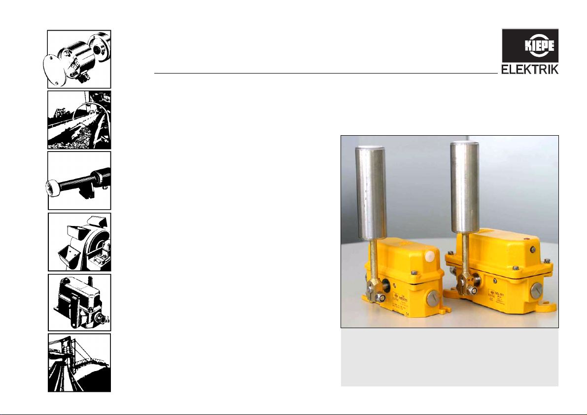
Belt misalignment switch
Type HES and SEL
OPERATING INSTRUCTIONS
Page 2

Legal Notice
CE conformity certificate
Operating instructions (Translation of original)
Document No.: 94.063 388.191
Belt misalignment switch, Type HES and SEL
Equipment identification no.: various
Date of Issue: 27.10.2008
Update Status: Index 0
The device complies with the relevant European and
national regulations.
CE conformity has been certified; the relevant records
and documents are in the hands of the manufacturer.
Protective note (as per DIN ISO 16016:2002-5)
Forwarding and duplicating this document, as well as
using or revealing its contents are prohibited without
written approval. Noncompliance is subject to
compensatory damages. All rights reserved with regard
to patent claims or submission of design or utility patent.
CONFIDENTIAL
www.kiepe-elektrik.com
Vossloh Kiepe GmbH
Kiepe-Platz 1
D–40599 Düsseldorf
Germany
Tel.: +49(0)211/7497–0
Fax: +49(0)211/7497–420
Page 3

Table of contents
1 For your safety..................................................................................................................5
1.1 Intended use .................................................................................................................................................5
1.2 Design of warnings .......................................................................................................................................5
2 Transport, storage and disposal .......................................................................................7
2.1 Transport and packaging ..............................................................................................................................7
2.2 Storage .........................................................................................................................................................7
2.3 Disposal ........................................................................................................................................................7
3 Description........................................................................................................................8
CONFIDENTIAL
4 Technical data ................................................................................................................10
4.1 General technical data................................................................................................................................10
4.2 Device identification....................................................................................................................................11
4.3 Device variants ...........................................................................................................................................12
4.4 Dimensions .................................................................................................................................................13
Table of contents
3
Operating instructions HES and SEL
Page 4

Table of contents
4
5 Mounting and dismounting .............................................................................................15
5.1 Scope of delivery........................................................................................................................................ 15
5.2 Mounting .................................................................................................................................................... 16
5.2.1 Mechanical mounting ................................................................................................................................. 16
5.2.2 Electrical connection .................................................................................................................................. 18
5.2.3 Adjusting the switch points......................................................................................................................... 21
5.2.4 Commissioning........................................................................................................................................... 23
5.3 Dismounting ............................................................................................................................................... 24
6 Maintenance...................................................................................................................25
7 Repairs ...........................................................................................................................26
7.1 Replacing the roller lever ........................................................................................................................... 26
8 Ordering devices, replacement parts and accessories ..................................................27
8.1 Ordering devices ........................................................................................................................................ 27
8.2 Ordering replacement parts and accessories ............................................................................................ 28
HES and SEL Operating instructions
CONFIDENTIAL
Page 5
1 For your safety
!
1 For your safety
5
1.1 Intended use
The belt misalignment switches HES and SEL are used
for monitoring the true running of continuous conveyors.
The switches serve to protect the belts from being damaged or destroyed if the belt deviates from its designed
running line. The device is intended for use in stationary
installations and vehicles.
The documentation at hand is to be considered part of
the product and must be retained and be available to the
respective owner/user for the entire service life of the
product. The documentation must be passed on to each
subsequent owner of the product.
CONFIDENTIAL
The manufacturer is not liable for personal injury and
property damage arising from non-intended use of the
device or unauthorized modifications to the device and
its components. Make sure that the intended use is not
impaired in any way even after unexpected outside influence on the device.
Intended use refers specifically to the operation of the
device in accordance with these operating instruc-
tions. Work on this device may only be carried out by
qualified personnel who are familiar with accident prevention regulations as well as other generally recog-
nized safety regulations.
By using the equipment as intended, you protect
yourself and prevent damage to the equipment and
its components.
1.2 Design of warnings
Risks are classified in accordance with ISO 3864-2 and
ANSI Z535.6 using the keywords
• “Danger,” “Warning,” and “Caution” in the case of
bodily injury,
• “Beware” in the case of property damage, and
• “Note” to convey general information.
In this documentation, the Risks and Notes are classified
and presented as follows:
Danger!
indicates the immediate threat of danger. Not avoiding
this danger will result in death or extremely serious injury (crippling).
Operating instructions HES and SEL
Page 6
1 For your safety
!!!
6
Warning!
indicates a possibly dangerous situation. Not avoiding
this dangerous situation could result in death or extremely serious injury (crippling).
Caution!
Icons
The following icons are used to more clearly define the
sources of danger. The icons can appear in reference to
any level of danger.
Icon Type of danger
Dangers of all types, except those that are
labeled with the following icon
indicates a possibly dangerous situation. Failure to
avoid this dangerous situation can result in light or minor injuries.
Beware!
indicates a possibly harmful situation. If this harmful situation is not avoided, the product or something in its vicinity could be damaged.
Note!
“Note” indicates advice on use and other especially helpful information.
HES and SEL Operating instructions
Table 1-1: Icons for general sources of danger
Injuries caused by dangerous voltages and
currents.
Damage caused by electrostatic
discharges (ESD protection)
CONFIDENTIAL
Page 7

2 Transport, storage and disposal
!
2.1 Transport and packaging
Select suitable packaging when sending the device or
components of the device to Vossloh Kiepe GmbH, e.g.
for repairs. In particular, ensure that the components are
kept clean and protected from shock and moisture. This
prevents damage to the components that may occur during transport, for which the manufacturer accepts no liability.
2.2 Storage
Avoid major temperature fluctuations, as these can lead
to condensation that can cause damage to the device
CONFIDENTIAL
and its components.
Permissible storage temperature: see Chapter 4: „Tech-
nical data", page 10
2 Transport, storage and disposal
Damage caused by storage
Dirt or water getting into the device and exposure to
weather (e.g. buildup of condensation in the device,
sunlight) damage the device and lead to faster deterioration.
Protect the device by storing it in a clean, dry place under stable ambient conditions. If possible, store the device in its original packaging.
2.3 Disposal
Only materials that are not considered hazardous according to current engineering practice are used for
Vossloh Kiepe GmbH products. Furthermore, we develop products that can be recycled after intended use. In
our selection of raw materials and components, we favor
reusable materials. This choice of materials used does
not compromise product safety in any way.
7
Operating instructions HES and SEL
Page 8
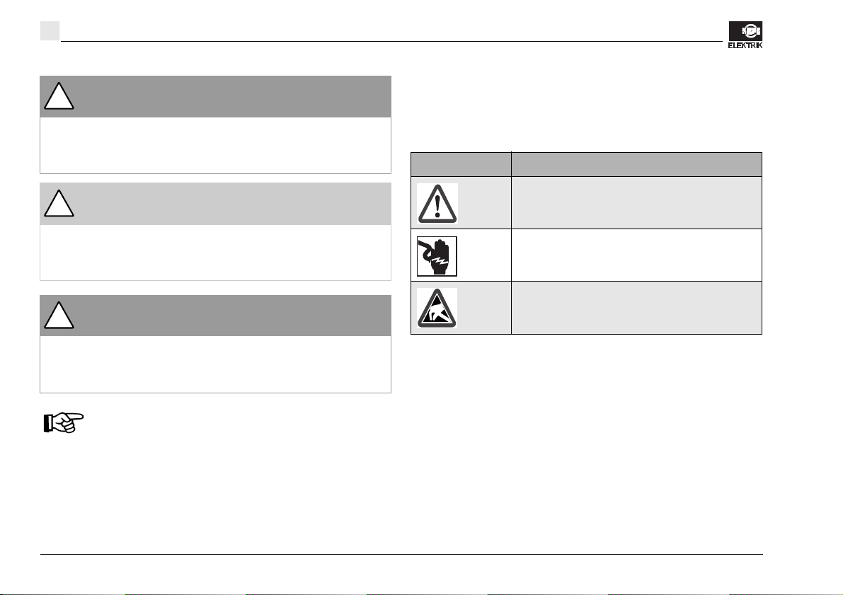
3 Description
Roller lever (3)
0
0: Basic position
1: Switch point at a deflection of 5° to 15°
2: Switch point at a deflection of 15° to 35°
3: Maximum deflection at 75°
1
1
2
2
3
3
8
3 Description
Belt misalignment switches are used in conveyor belt
systems subjected to especially severe operating conditions for monitoring the true running of continuous conveyors (see section 1.1: „Intended use“, page 5). The
belt misalignment switches serve to protect the belts
from being damaged or destroyed if the belt deviates
from its designed running line. Upstream systems can be
stopped in time to avoid material spillage or operational
malfunctions.
The roller lever (3) of the belt misalignment switch is
made of stainless steel and contains ball bearings for improved handling of lateral forces and impacts. The
48 mm roller diameter means the device can be used at
high belt speeds. All external parts are either made of
stainless steel or have a special galvanized coating.
The roller lever (3) of the belt misalignment switches can
be moved in both directions (see fig. 3-1). By moving the
roller lever (3) the cam discs (11) are turned (see fig. 3-
2). The cam discs (11) operate the switches (7). The cam
discs (11) are adjustable and make it possible to adapt
the switch points to local conditions.
CONFIDENTIAL
HES and SEL Operating instructions
Fig. 3-1: Belt misalignment switch - switch points (adjust-
able)
Page 9

3 Description
Fig. 3-2: Belt misalignment switch – view with roller lever re-
moved
Cam disc (11)Switch (7)
Fig. 3-3: Paired belt misalignment switches mounted on the
conveyor
Upper or lower belt of the
conveyor
Roller lever (3)
* Belt edge must actuate the roller lever (3) in the lower half of
the roller.
Distance between belt edge and
roller lever (3): 10…20 mm
*
9
The belt misalignment switch, for example, can be adjusted in such a way that when it reaches the first switch
point, an advance warning (adjustment range: 5° to 15°)
is triggered and when it reaches the second switch point,
the conveyor belt system is switched off (adjustment range: by prying out a cam by 15° to 35°). The mechanical
stop of the roller lever (3) is reached at a deflection of
75°.
CONFIDENTIAL
Belt misalignment switches are mounted in pairs on the
upper belt in front of the drive roller, on the lower belt in
front of the deflection roller and also on critical spots
where the axis distances are larger or material is
transferred (see fig. 3-3).
Operating instructions HES and SEL
Page 10

4 Technical data
10
4 Technical data
4.1 General technical data
In compliance with the following
standards and regulations
Suitable for Controls and installations according to EN 60204
Casing HES: Aluminum, SEL: Gray cast iron
Mounting HES: two slotted holes for M 8 screws
Permissible ambient temperature -25°C to +70°C, see also Section 4.3, page 12
Permissible storage temperature - 25 °C to + 70 °C, see also Section 4.3, page 12
Max. altitude above sea level 2.000 m (contact manufacturer for installation on sites at higher altitudes)
Protection standard IP 67 according to EN 60529
Switching system Snap-acting switch, max. four positive-opening change-over contacts, see also
Type of drive Cylindrical roller made from stainless steel, Ø 48 mm
Switch points Adjustable: 5° to 15° and 15° to 35°
Deflection of the roller lever Max. 75°
Rated insulation voltage U
Conventional thermal current I
Breaking capacity AC-15: Ue = AC 230 V, Ie = 1.5 A
i
th
EN 60947-5-1
VDE 0110 – Pollution degree 2 (inside), 4 (outside)
SEL: two slotted holes for M 10 screws
Section 4.3, page 12
Default setting: 2 x 10°
AC 380 V, DC 250 V
6A
DC 24 V, t = 2 ms to 3 ms, to 3 A
CONFIDENTIAL
HES and SEL Operating instructions
Page 11

Conductor infeed Tapped hole for 2 x M25 x 1.5
Fig. 4-1: Printed impression
Type identification
Product number: Basic
number and variant
number
Line connection cross-section 0,75 mm2 to 1.5 mm
Protective conductor connection In the casing, M4, protective conductor cross-section max. 2.5 mm
Weight HES: approx. 1820 g
4.2 Device identification
The devices are marked with a device identification number consisting of an 8-digit basic number and a 3-digit
variant number:
Type Basic number Variant number
CONFIDENTIAL
HES 92.057020. see section 4.3, page 12
SEL 92.056979. see section 4.3, page 12
You will find the exact type and variant number on the rating plate on the exterior of the casing.
4 Technical data
1 x screwed cable gland M25 x 1.5; sealing area Ø 11 mm to Ø 16 mm
1 x dummy plug M25 x 1.5
2
SEL: approx. 5500 g
11
Operating instructions HES and SEL
Page 12

12
4 Technical data
4.3 Device variants
Variant number Type Technical data (see section 4.1)
0xx, 1xx Basic device without/with signal lamp –
2xx Basic device with DUPLINE module also see the "DUPLINE module for belt
3xx Basic device additional screwed cable gland
4xx Basic device additional switch configuration
5xx Basic device with UL approval UL approval
6xx Roller lever limit switch See operating instructions 94.062556.191
7xx Basic device with expanded temperature range HES711: -40°Cto+80°C
8xx – –
9xx Special devices –
1
misalignment switches" operating instructions:
HES 21x: 94.063896.191
HES 22x, HES 23x: 94.063897.191
SEL 21x: 94.063898.191
SEL 22x, SEL 23x: 94.063899.191
CONFIDENTIAL
1. Deviations are possible for certain types.
HES and SEL Operating instructions
Page 13

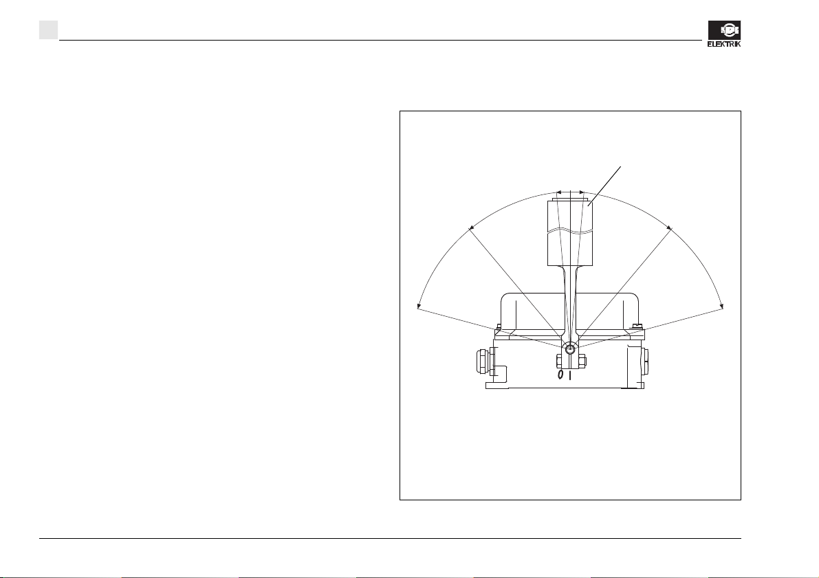
M8
98
8,5
Ø 48
54
284
111
M 25 x 1,5
7
M25 x 1,5
176
162
4.4 Dimensions
CONFIDENTIAL
4 Technical data
13
Fig. 4-2: HES dimensions
Operating instructions HES and SEL
Page 14

14
119,5
291
124
70
M10
M25 x 1,5
M25 x 1,5
205
177
11
Ø 48
12
4 Technical data
Fig. 4-3: SEL dimensions
HES and SEL Operating instructions
CONFIDENTIAL
Page 15

5 Mounting and dismounting
Fig. 5-1: Scope of delivery
Dummy plug (25)
Screwed cable gland (6)
!
5.1 Scope of delivery
The belt misalignment switches are delivered ready to
operate. The screws for mechanical fastening are not included in the scope of delivery.
One screwed cable gland (6) and one dummy plug (25)
are included in the scope of delivery (see fig. 5-1).
CONFIDENTIAL
5 Mounting and dismounting
Beware!
The device must only be operated when all three holes
are closed with the supplied cable gland (6) and the
dummy plug (25). Only use the supplied screwed cable
gland (6) and dummy plugs (25), otherwise the seal can
no longer be guaranteed.
15
Operating instructions HES and SEL
Page 16

5 Mounting and dismounting
!
!
!
Fig. 5-2: Mounting paired belt misalignment switches on the
conveyor
Upper or lower belt of the
conveyor
Roller lever (3)
* Belt edge must actuate the roller lever (3) in the lower half of
the roller.
Distance between belt edge and
roller lever (3): 10…20 mm
*
16
5.2 Mounting
Danger of fatal electric shock
Work on the device may be performed only by a qualified electrical technician.
Prior to working, switch off the power supply to the system. Ensure that the system cannot be accidentally
switched on. Mask any neighboring components that
may be live to prevent contact.
Beware!
The belt misalignment switches are to be used in control circuits only.
Beware!
The device must only be operated when all three holes
are closed with the supplied cable gland (6) and the
dummy plug (25). Only use the supplied screwed cable
gland (6) and dummy plugs (25), otherwise the seal can
no longer be guaranteed.
5.2.1 Mechanical mounting
Beware!
Make sure to mount the belt misalignment so that the
belt edge actuates the roller lever (3) in the lower half of
the roller when the belt deviates from its designed running line. This prevents the belt from sliding over the
roller lever (3) (see fig. 5-2).
Belt misalignment switches are mounted in pairs on the
upper belt in front of the drive roller, on the lower belt in
front of the deflection roller and also on critical spots
CONFIDENTIAL
HES and SEL Operating instructions
Page 17

5 Mounting and dismounting
Fig. 5-3: Mounting the belt misalignment switch onto the con-
veyor
Long hole (10)
Fig. 5-4: Mounting the roller lever on the belt misalignment
switch
Nut (9)
The roller lever (3) must not
come into contact with the
cover (2) when moving.
Shaft (14)
17
where the axis distances are larger or material is transferred (see fig. 5-2).
1. Prior to working, switch off the power supply to the
2. Secure the belt misalignment switches on the con-
CONFIDENTIAL
system. Ensure that the conveyor system cannot be
accidentally switched on. Mask any neighboring
components that may be live to prevent contact.
veyor structure (see section 4.4: „Dimensions“, page
13). Secure the belt misalignment switches by
screwing two screws through the long holes (10)
(see fig. 5-3).
In order to minimize roller lever (3) wear, mount the roller
lever (3) in such a way that it is located approximately 10
to 20 mm in front of the belt edge (see figures 5-2 and 5-
4).
3. Fit the roller lever (3) onto the shaft (14).
Operating instructions HES and SEL
Page 18

5 Mounting and dismounting
Fig. 5-5: Mounting the roller lever on the belt misalignment
switch
Nut (9)
The roller lever (3) must not
come into contact with the
cover (2) when moving.
Shaft (14)
!
!
!
18
Beware!
When tightening the nut (9), make sure the distance to
the cover (2) is sufficient enough so that the roller lever
(3) will not come into contact with the cover (2) when the
roller lever (3) is moving.
4. Set the roller lever (3) to the required position and
retighten the self-locking nut (9).
5.2.2 Electrical connection
Danger of fatal electric shock
Work on the device may be performed only by a qualified electrical technician.
Prior to working, switch off the power supply to the system. Ensure that the system cannot be accidentally
switched on. Mask any neighboring components that
may be live to prevent contact.
Danger!
Only use connection cables with a diameter of at least
11 mm up to a maximum of 16 mm. The permissible
conductor cross-sections can be found in Chapter 4:
„Technical data", page 10.
Penetration of dirt and water when gaskets
are damaged
If gaskets are damaged, dirt and water can penetrate
into the device and damage the device and its components.
Check gaskets for damage before assembling. If the
gasket is damaged, exchange the device cover.
CONFIDENTIAL
HES and SEL Operating instructions
Page 19

5 Mounting and dismounting
Fig. 5-6: View of the belt misalignment switch connections
Switch (7)
Screwed cable gland (6)
Protective conductor
connection M4 (8)
Cover (2)
Gasket (22)
Cam disc (11)
Casing (1)
Fig. 5-7: Connection diagram in the belt misalignment switch
cover
19
CONFIDENTIAL
1. Prior to working, switch off the power supply to the
system. Ensure that the conveyor system cannot be
accidentally switched on. Mask any neighboring
components that may be live to prevent contact.
2. Open the cover (2) of the belt misalignment switch
by loosening the two screws (5).
3. Loosen the nut on the screwed cable gland (6) and
thread the connection cable (Ø 11 mm to Ø 16 mm)
through it (see fig. 5-6).
4. Connect the connection cable to the terminals of the
switch (7) in the cover (2) of the belt misalignment
switch according to the connection diagram (see
fig. 5-7).
5. Attach the protective conductor (max. 2.5 mm
protective conductor connection M4 (8) (conductor
cross-sectional area depending on supply line, subject to a maximum of 2.5 mm
The factory setting for the switch points of the belt misalignment switches is 10° in both directions. The switch
points of the belt misalignment switches can be adjusted
as required.
6. Adjust the switch point of the roller lever (3) on the
cam disc (11), if a different switch point is required
2
).
X1 X2
2
) to
Operating instructions HES and SEL
Page 20

5 Mounting and dismounting
Fig. 5-8: Mounting the belt misalignment switch onto the con-
veyor
Screw (5)
Screw (5)
Cover (2)
Screwed cable gland (6)
Dummy plug (25)
!
20
(see section 5.2.3: „Adjusting the switch points“,
page 21).
7. Tighten the nuts of the screwed cable gland (6) with
a tightening torque of 6.7 Nm.
Beware!
A device with a damaged gasket (22) must not be used.
Remove any dust that may have entered the casing (1).
8. Check the gasket (22) of the cover (2) for damage.
9. Close the cover (2) of the belt misalignment switch.
10. Secure the cover (2) with the screws (5).
Tighten the screws (5) evenly with a tightening
torque of 1.5 Nm.
11. Put the belt misalignment switch into operation (see
section 5.2.4: „Commissioning“, page 23).
CONFIDENTIAL
HES and SEL Operating instructions
Page 21

5.2.3 Adjusting the switch points
Fig. 5-9: Adjusting the switch points
Roller lever (3)
0
0: Basic position
1: Switch point at a deflection of 5° to 15°
2: Switch point at a deflection of 15° to 35°
3: Maximum deflection at 75°
1
1
2
2
3
3
The factory setting for the switch points of the belt misalignment switches is 10° in both directions. The "Advance Warning" and "Switch Off" switch points can be
adjusted as required.
CONFIDENTIAL
Operating instructions HES and SEL
5 Mounting and dismounting
Danger of fatal electric shock
Work on the device may be performed only by a qualified electrical technician.
Prior to working, switch off the power supply to the system. Ensure that the system cannot be accidentally
switched on. Mask any neighboring components that
may be live to prevent contact.
1. Prior to working, switch off the power supply to the
system. Ensure that the conveyor system cannot be
accidentally switched on. Mask any neighboring
components that may be live to prevent contact.
2. Open the cover (2) of the belt misalignment switch
by loosening the two screws (5) (see fig. 5-8).
Note
There are two screws (15) in each of the two
cams (11) (see figure 5-10, page 22). With one
screw (15), the cam (11) is fixed in its basic setting. The second screw (15) is screwed into the
cam (11).
To adjust the cam (11), the first screw (15) is
loosened just enough that the cam (11) can be
turned. The screw (15) can remain in the device. After being adjusted, the cam (11) is fixed
with the second screw (15).
21
Page 22

5 Mounting and dismounting
Fig. 5-10: Adjusting the switch points – Loosening screws in
the cam disc
Cam discs (11)
Screws (15)
Roller lever (3)
Fig. 5-11: View of the belt misalignment switch connections
Cam (12)
Switch (7)
Screwed cable gland (6)
Cover (2)
Gasket (22)
Casing (1)
Cam disc (11)
Dummy plug (25)
22
Especially with small changes in the setting, this
prevents the cam (11) from being turned back to
its original position when the screw (15) is tightened.
3. Adjust the switch point 1 (advance warning) (see
figures 5-9 and 5-10).
Adjustment range: 5° to 15°
a. Loosen the screw (15) in the cam (11) enough
that you can turn the cam (11).
b. Adjust the switch point 1 (advance warning) by
turning the cam (11).
c. Tighten the second screw (15) so that the cam
(11) is fixed in the newly set position.
4. Adjust the switch point 2 (switch off).
Adjustment range: 15° to 35°
a. Pry the cam (11) out of the cam disc (12) to
obtain a larger adjustment range.
b. Loosen the screw (15) in the cam (11) enough
that you can turn the cam (11).
c. Adjust the switch point 2 (switch off) by turning
the cam (11).
CONFIDENTIAL
HES and SEL Operating instructions
Page 23

5 Mounting and dismounting
!
Fig. 5-12: Commissioning the belt misalignment switch
Screw (5)
Screw (5)
Cover (2)
Screwed cable gland (6)
Dummy plug (25)
!
23
5. Check the set switch points (see figure 5-9, page
A device with a damaged gasket (22) must not be used.
Remove any dust that may have entered the casing (1).
6. Check the gasket (22) of the cover (2) for damage.
7. Close the cover (2) of the belt misalignment switch.
8. Secure the cover (2) with the screws (5) (see
CONFIDENTIAL
9. Put the belt misalignment switch into operation (see
5.2.4 Commissioning
1. Before putting the belt misalignment switch into
d. Tighten the second screw (15) so that the cam
(11) is fixed in the newly set position.
21).
Beware!
figure 5-12, page 23).
Tighten the screws (5) evenly to a tightening
torque of 1.5 Nm.
section 5.2.4: „Commissioning“, page 23).
operation, ensure that it is sealed (see fig. 5-12):
– Ensure that the screws (5) on the cover (2) are
tightened with a tightening torque of 1.5 Nm.
– Check that the screwed cable gland (6) is
tightened with a tightening torque of 6.7 Nm.
– Check that the dummy plug (25) is fastened
tightly.
2. Check the entire belt misalignment switch and its
components for damage.
Danger!
Always replace damaged belt misalignment switches.
Operating instructions HES and SEL
Page 24

5 Mounting and dismounting
Fig. 5-13: Removing the belt misalignment switch from the
conveyor
Switch (7)
Screwed cable gland (6)
Protective conductor
connection M4 (8)
Cover (2)
Cam disc (11)
Casing (1)
!
24
5.3 Dismounting
Danger!
Danger of fatal electric shock
Work on the device may be performed only by a qualified electrical technician.
Prior to working, switch off the power supply to the system. Ensure that the system cannot be accidentally
switched on. Mask any neighboring components that
may be live to prevent contact.
Open the belt misalignment switch only after it is de-energized.
1. Prior to working, switch off the power supply to the
system. Ensure that the conveyor system cannot be
accidentally switched on. Mask any neighboring
components that may be live to prevent contact.
2. Open the cover (2) by loosening the two screws (5)
(see figure 5-12, page 23).
3. Release the screwed cable gland (6) (see fig. 5-13).
4. Disconnect all electrical connections and pull the
cables out of the screwed cable gland (6).
5. Loosen both screws that fasten the belt misalignment switch through the long holes to the conveyor
system (see figure 5-3, page 17) and remove the
belt misalignment switch.
CONFIDENTIAL
HES and SEL Operating instructions
Page 25

6 Maintenance
Fig. 6-1: Checking the belt misalignment switch
Switch (7)
Screwed cable gland (6)
Protective conductor
connection M4 (8)
Cover (2)
Gasket (22)
Cam disc (11)
Casing (1)
!
Check the belt misalignment switch at regular intervals
(approximately every three months) for proper status and
trouble-free functionality.
CONFIDENTIAL
6 Maintenance
Danger!
Damaged belt misalignment switches or damaged components (e.g. bolted connections, gaskets) must not to
be used.
Always replace damaged belt misalignment switches.
25
Operating instructions HES and SEL
Page 26

7 Repairs
!
Fig. 7-1: Replacing the roller lever
Nut (9)
The roller lever (3) must not
come into contact with the
cover (2) when moving.
Shaft (14)
26
7Repairs
7.1 Replacing the roller lever
Danger of fatal electric shock
Work on the device may be performed only by a qualified electrical technician.
Prior to working, switch off the power supply to the system. Ensure that the system cannot be accidentally
switched on. Mask any neighboring components that
may be live to prevent contact.
Beware!
When tightening the nut (9), make sure the distance to
the cover (2) is sufficient enough so that the roller lever
(3) will not come into contact with the cover (2) when the
roller lever (3) is moving.
4. Set the roller lever (3) to the required position and
tighten the self-locking nut (9) using an 16 mm openend wrench.
1. Prior to working, switch off the power supply to the
system. Ensure that the conveyor system cannot be
accidentally switched on. Mask any neighboring
components that may be live to prevent contact.
2. Loosen the nuts (9) using a 16 mm open-end
wrench and remove the roller lever (3) from the shaft
(14) (see fig. 7-1).
In order to minimize wear of the roller lever (3), mount the
roller lever (3) in such a way that it is located approximately 10 to 20 mm in front of the belt edge (see figure 5-
2, page 16).
3. Fit the new roller lever (3) onto the shaft (14).
HES and SEL Operating instructions
CONFIDENTIAL
Page 27

8 Ordering devices, replacement parts and accessories
Fig. 8-1: HES printed impression
Type identification
Product number: Basic
number and variant
number
Fig. 8-2: SEL printed impression
Type identification
Product number: Basic
number and variant
number
8.1 Ordering devices
Please provide the following data with every order (see
legal notice for company address):
1. Belt misalignment switch model
2. Product number (see rating plate on casing cover):
CONFIDENTIAL
(see rating plate on casing): e.g. HES 011
e.g. 92.057020.011.
8 Ordering devices, replacement parts and accessories
27
Operating instructions HES and SEL
Page 28

8 Ordering devices, replacement parts and accessories
Fig. 8-3: Replacement parts
Roller lever (3)
Screwed cable gland (6)
Dummy plug (25)
28
8.2 Ordering replacement parts and
accessories
Please provide the following data with every order (see
legal notice for company address):
1. Belt misalignment switch model
(see rating plate on casing): e.g. HES 011
2. Product number (see rating plate on casing cover):
e.g. 92.057020.011.
3. Order information and order number (see table):
Item Order information Order number
3 Control lever with roller (roller
lever)
6 Screwed cable gland 113.52.02.20.01
25 Closure screw (dummy plug) 113.52.87.20.02
93.058650.001
CONFIDENTIAL
HES and SEL Operating instructions
Page 29

CONFIDENTIAL
29
Operating instructions HES and SEL
Page 30

Vertrieb Schweiz
APS systems AG Tel. +41 (0) 62 389 88 88
Neumatt 4 Fax. +41 (0) 62 389 88 80
Schweiz Web www.kiepe-elektrik.ch
4626 Niederbuchsiten Mail info@kiepe-elektrik.ch
 Loading...