

Kiefer INDULVENT ec Installation, Operation And Maintenance Instructions

Installation, Operation and Maintenance Instructions
Comfort Ceiling Fan Coil System
INDULVENT ec
• Draught-free ambient air distribution with up to 2600 W cooling capacity
• Low sound power level
• Only electrical, cooling water and condensate connections required
• Energy-saving EC technology
• Stepless power regulation
• Integral condensate pump
• Open BUS architecture
Kiefer Luft- und Klimatechnik Comfort Ceiling Fan Coil System INDULVENT ec Page 2 / 22
www.kieferklima.de Technical modifications reserved
CONTENTS
Features 2
Safety instructions 3
Function 4
Functions and dimensions 5
Technical data 6
Technical data and maintenance 15
Maintenance 16
Technical data 17
Specification text 20
EC declaration of conformity 21
F
EATURES
Local ceiling fan coil systems allow the flexible use
of available space. For high comfort requirements,
INDULVENT ec ensures draught-free ambient air
flow with high cooling capacity and low sound power
levels. The compact unit employs a fan with energysaving EC technology. Cooling capacities of up to 2600
W can be accommodated. Only electrical, cooling water
and condensate connections are required. Suitable for
the installation in all prevalent modular ceilings.
INDULVENT ec performance features
Compact design
Fan, heat exchanger, dust protection, ambient air
temperature sensor and controller are all integrated in a
single housing.
Up to 2600 W cooling capacity (sensible + latent)
per unit for high cooling loads.
Only a cold-water supply and mains voltage
are needed for operation.
Draught-free air circulation
according to DIN EN 13 779, results from the highinduction, integrated, ceiling air diffuser. Average local
air velocities of less than 0.15 m/s can be achieved.
Housing with internal insulation
using halogen-free closed-cell insulation material.
Fire-resistance classification (BKZ) B2.
Simple operation and maintenance
The folding hinge fitted as standard to the front panel
makes servicing easy.
Easy to clean (VDI 6022)
because all internal parts are easily accessible. Just a few
simple operations and the housing, ventilator, heat exchanger, condensate dish etc. are accessible for maintenance and cleaning.
Integral cooling regulation
adapts the cooling capacity to the load situation in a room
by changing the recirculation air flow rate.
Vent-BUS
is an internal communication system which can conect
up to 32 subscribers to a common BUS. Any desired
combination of individual units and master/slave groups is
possible.
Comfortable operation, parameterisation and monitoring
using a PC or a laptop via the USB socket in the front
panel. With the VENT-BUS, any connected unit can be
addressed and parameterised from the USB interface of
any convenient subscriber.
Flexible
Because parameterisation is simple, the works control
parameters can be changed to individual settings when
required. If usage changes, new master/slave groups can
be set up at any time.
Comprehensive equipment
The basic unit includes signal contacts for operation and
fault messages. An external control using a 0-10V DC
control voltage is possible. Condensate pump is fitted as
standard to ensure the reliable removal of any condensate
for construction height 335 mm.
Accessories
● Remote switching point with the functions:
OFF – STAGE 1 – STAGE 2 – AUTOMATIC
● Through valve (¾“) with thermal actuator to cut off cold
water during standstill periods
● Coupler to incorporate the Vent-BUS in an in-house
BUS system
Please note:
Before commissioning the INDULVENT ec, please read the
following operating instructions carefully! Non-compliance
with instructions can result in danger to persons and the
environment, and the invalidation of claims.
T
ABLE OF
C
ONTENTS
/ FEATURES
Kiefer Luft- und Klimatechnik Comfort Ceiling Fan Coil System INDULVENT ec Page 3 / 22
www.kieferklima.de Technical modifications reserved
Proper use
The INDULVENT ec ceiling fan cooling unit is intended
for cooling rooms and indoor spaces. When the temperature in the heat exchanger is below the dew point,
the ambient air entering the unit is dehumidified as well
as cooled. The unit incorporates electronic power regulation. The ceiling fan cooling unit must not be used as
a safety component, nor used in situations where it
must provide safety-relevant functions.
Operating location
The unit is intended for use in dry indoor rooms with
ambient temperatures in the range 10-40 °C. The uni t is
designed for use in locations where the air quality is
typical of that found in offices from the points of view of
dust concentrations and the presence of corrosive and
oily substances.
Safety instructions
• Work on the unit shall only be carried out by qualified personnel, and only when the mains plug has
been disconnected (power supply switched off).
• The unit shall only be operated when the front plate
is closed.
• When the front plate is open there is a risk of injuries from rotating parts (fan).
• Assembly and installation of the units and components shall only be carried out by qualified personnel.
• Installation, connection and operation of the units
and components must be within the conditions for
application and operation as specified in the operating instructions, and comply with valid regulations.
• The operational safety of the units and components
is only guaranteed for proper use for units in their
fully assembled state.
• Do not operate units or components with evident
defects or damage.
• Installation, repairs and maintenance shall be carried out exclusively by authorised specialist personnel; visual inspections and cleaning can be undertaken by the user. When working on the fan, even
after the mains plug has been disconnected, there
may still be dangerous voltages present due to residual charge in the capacitors in the motor unit. For
this reason wait at least five minutes after disconnecting before performing any work on the motor
unit.
• Before carrying out maintenance or repair work on
the fan, allow time (at least five minutes) for the
electronics housing to cool sufficiently; it is located
directly above the fan. Danger of burns!
• The units and components must not be subjected to
mechanical loads, extreme humidity or direct sunlight.
• It is forbidden to operate the units in areas in which
explosive atmospheres may occur.
• Installation in aircraft or railcars is forbidden without
approval from the manufacturer.
Environmental protection and recycling
Disposal of packing materials
All products are carefully packed for transport in environmentally-friendly materials. You make a valuable contribution to the reduction of waste and conservation of raw materials when you dispose of the packing materials only at
an appropriate collection point.
Transport and packing
The units are supplied in sturdy transport packages. Please
check the units immediately they are delivered and make a
note of any signs of damage or missing parts on the delivery note. Inform the forwarding agent and your contract
partner. We provide no guarantee for complaints made
later.
For packaged goods the following conditions apply:
• They must not be stored outdoors
• They must be stored in a dry, dust-free place
• They must be protected against moisture
• They must not be subjected to corrosive or aggressive
media
• They must be protected from direct sunlight
• Storage temperature: 5 °C to 40 °C
• Relative humidity: 20 % to 90 %
Please note:
All instructions in these Operation and Maintenance Instructions are given on the basis of the currently valid
standards and regulations, and the current state of the art.
The manufacture accepts no liability for damage due to:
• Improper use
• Non-compliance with these instructions
• Installation and operation by qualified personnel who
have not been properly instructed
• Technical modifications / tampering with the unit
• Failure to observe maintenance periods
• Use of unauthorised spare parts
S
AFETY
I
NSTRUCTIONS
Kiefer Luft- und Klimatechnik Comfort Ceiling Fan Coil System INDULVENT ec Page 4 / 22
www.kieferklima.de Technical modifications reserved
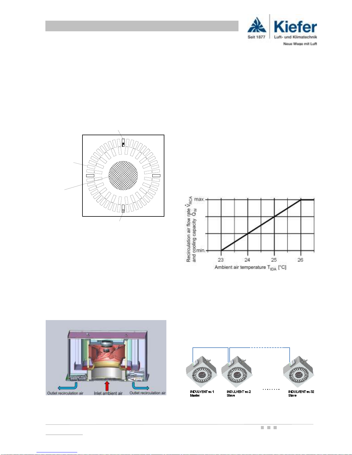
Front plate
The front plate is divided into two guide zones. In the
centre of the front plate there is a round air-inlet opening with a dust-protection filter behind it. In the outer
region, there is a rotationally symmetrical hole pattern,
which incorporates proven, highly inductive INDULCLIP
air guide elements.
Air flow paths
A radial fan draws warm room air into the unit through
the central air inlet in the front plate. This air flows in the
inlet port through a dust filter to protect the internal
parts against the build up of dust and dirt.
The annular heat exchanger cools the recirculation air
drawn in to a temperature which is determined by the cooling water. The outer part of the front plate guides the
cooled recirculation air back into the room through highly
inductive elements to ensure draught-free comfort.
Below the heat exchanger there is a dish for any condensate that collects; the condensate either drains away down
natural gradients or is removed by an integral condensate
pump.
The temperature of the ambient air entering the unit is
recorded by an internal room temperature sensor. The
integrated electronic controller reacts to this ambient air
temperature or to an external control signal. By changing
the speed of rotation, and so the volume flow of recirculation air, the cooling capacity is continually adapted to the
cooling load of a room.
Example of parameter setting
Function of the integral electronic controller in standard automatic operation
If several units are operated in the same control zone, one
master unit can control up to 31 slaves units on the twowire BUS (Vent-BUS). The master sets the speed of rotation of all connected slave units on the basis of the ambient
air temperature it measures.
F
UNCTION
Air outlet zone
with INDULCLIP
air guide
elements
Recirculation
Front plate fastener
Signal diodes, red/green
air inlet
Kiefer Luft- und Klimatechnik Comfort Ceiling Fan Coil System INDULVENT ec Page 5 / 22
www.kieferklima.de Technical modifications reserved
A USB interface with two signal diodes for monitoring
and parameterisation of the unit is integrated into the
front plate. The current operating state can thus be
determined from within the room. In addition the ceiling
fan cooler has an operation and fault-signal relay.
The hinged front plate makes servicing especially easy.
It allows quick opening and closing for cleaning and
maintenance. The front plate is made of zinc-plated
steel sheet and powder-coated; its colour is RAL 9010.
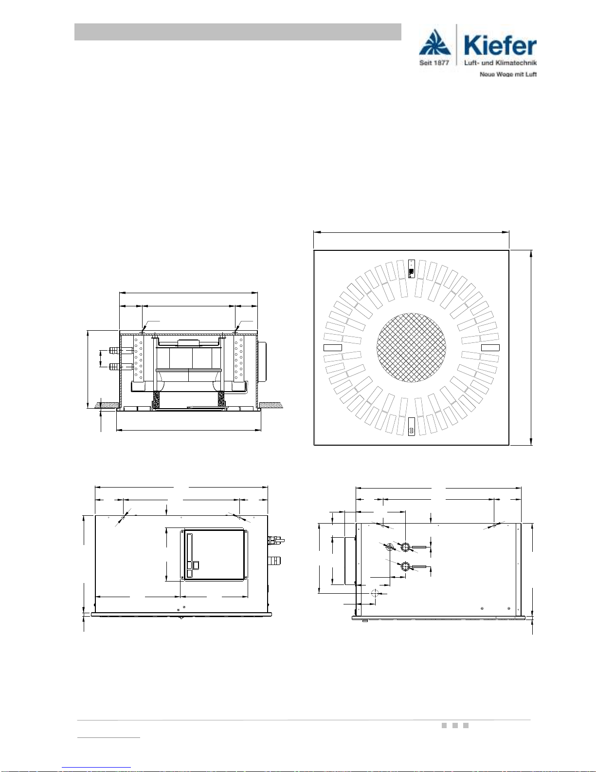
Sectional view with major dimensions
Side view showing electrical connection
* 335 mm with condensate pump
* 375 mm with gravity condensate drain
Other RAL colours are available on request. The air guide
elements and grille covers of the front plate can be supplied in black or light grey at the buyer's choice. Here too,
other colours are available on request.
The housing is made from zinc-plated steel sheet. The heat
exchanger is manufactured from AlCu, and the condensate
dishes from flame-retarded, impact-resistant ABS plastic.
Operating weight ca. 31 kg
View from the room (front plate)
Side view showing cold-water and condensate connections
All dimensions in mm
F
UNCTION AND
D
IMENSIONS
623
623
623
12
70
Ø9
Ø9
400
596 x 594
98 98
623
335 (375)*
12
70
Ø9
Ø9
400
596 x 59
98 98
596
98 400 98
Ø
9
Ø
9
295 233
184 43
335 (375)*
12
594
97 97
Ø
9
Ø
9
400
40
Ø
9
Ø
3
/
4
"
Ø
9
69
253
170 50
122
86
179
335 (375)*
12
57
Ø
3
/
4
"
70
Feed line
Return line
Kiefer Luft- und Klimatechnik Comfort Ceiling Fan Coil System INDULVENT ec Page 6 / 22
www.kieferklima.de Technical modifications reserved
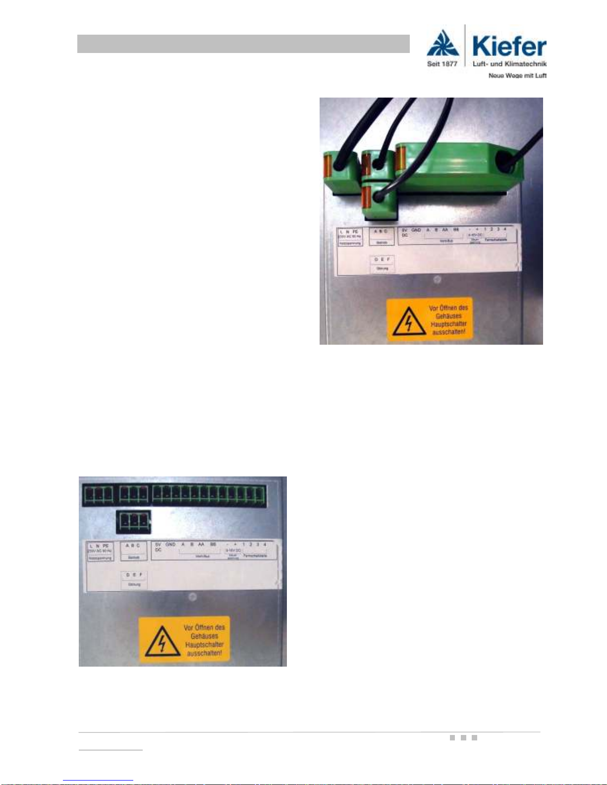
E
LECTRICAL CONNECTION BOX
The electrical connections and the internal electronics
are located on the central controller PCB in the terminal
box.
For starting up, the INDULVENT ec ceiling fan cooler
requires an overload protection circuit breaker Type C
to EN 60898, DIN VDE 0641 Part 11. The maximum
power requirement during operation is 70 W per unit.
We recommend that not more than ten units are connected to any one circuit breaker, so as to prevent the
circuit breaker tripping out when starting up.
For power supply, for connecting remote switching
points, operation and fault-message contacts, and for
communication, there are coded connection sockets.
The appropriate mains connection plug is included in
the scope of supply.
The electrical connection of a unit shall only be carried
out by a qualified electrical specialist.
When commissioning a unit and when carrying out any
service operations that may be needed, access to the
electrical connection box is not necessary. All desired
settings can be carried out via the USB interface on the
front plate using a laptop computer. A software CD with
installation and operating instructions is included with
every delivery (the software can also be downloaded at
www.kieferklima.de).
Electrical terminal box in as-supplied condition
Electrical terminal box completely connected (only the
mains plug is supplied as standard)
I
NSTALLATION
Installation / suspension from the bare ceiling is by means
of a sufficient number of adequately dimensioned threaded
rods or rapid hangers. Units must be mounted so that they
are freely suspended and not preloaded, and there must be
provision for thermal expansion. The transmission of vibrations and structure-borne noise to the building must be
avoided; they can lead to acoustic problems. There must
be a space of at least 25 mm between the upper surface of
the unit and the lower surface of the bare ceiling.
T
ECHNICAL DATA
Kiefer Luft- und Klimatechnik Comfort Ceiling Fan Coil System INDULVENT ec Page 7 / 22
www.kieferklima.de Technical modifications reserved
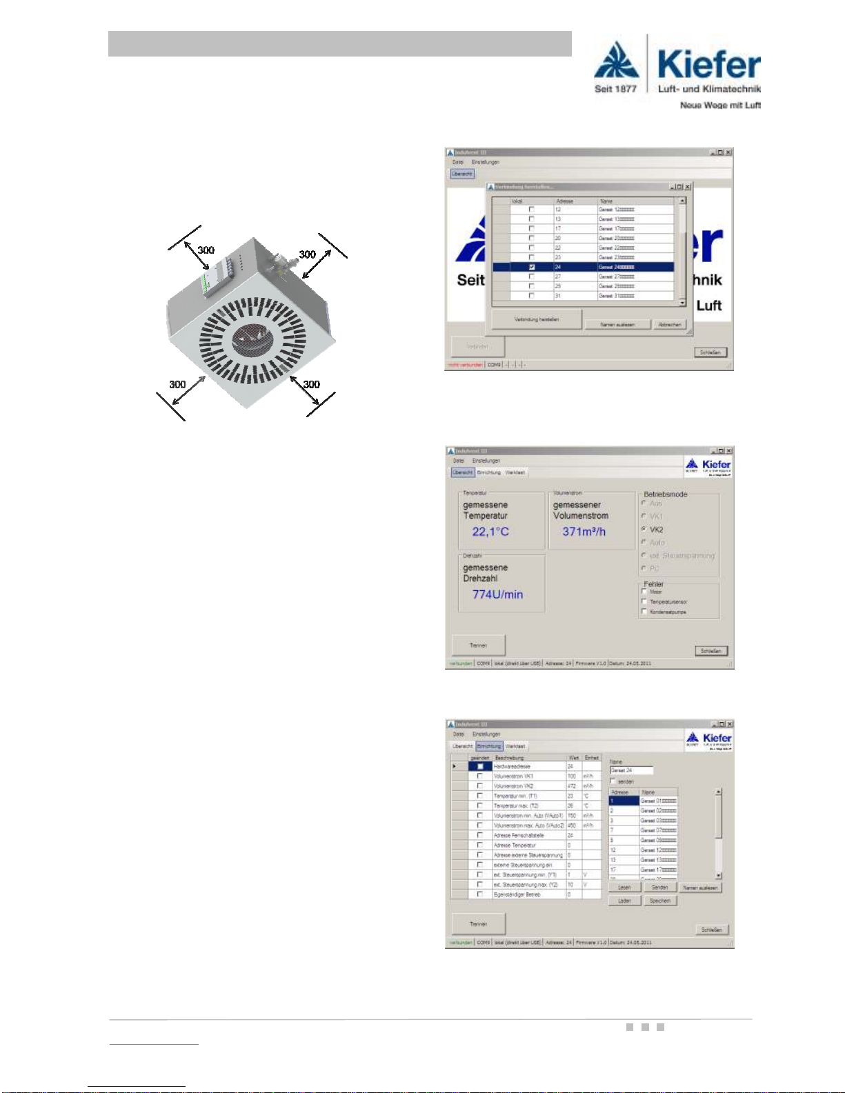
Installation - minimum spacing
The following minimum distances to building features
must be observed to provide space for maintenance
and repair work within the intermediate ceiling.
Access hatches
All regular maintenance work can be carried out without
an opening in the intermediate ceiling. For replacement
of the controller or the heat exchanger, however, a
suitable access hatch must be provided. The optional
through valve is supplied loose. It is therefore not possible to make a recommendation regarding where an
access hatch should be provided.
D
ISPLAY AND PARAMETERISATION
The INDULVENT ec comfort ceiling fan coil system has
an internal BUS, which is based on an RS 485 two-wire
interface. Every unit on the BUS can be called up, interrogated, and parameterised from any other BUS subscriber.
Via the USB socket on the front plate, you can connect
an INDULVENT to a laptop without opening the unit.
The necessary operating and parameterisation software
and a description are on a CD supplied with the unit. An
installation assistant helps set up the program. Once a
connection has been made, the unit can be parameterised using the graphic user interface. All the settings
necessary for operation of the unit can be read and
changed. When necessary an updated version of the
operating software (firmware) can also be installed.
For more information about INDULVENT ec PC software, please see our detailed software description at
www.kieferklima.de. On request we will send you the
software description by post.
Screenshot showing selection of a unit connected to
the Vent-BUS after activation of the USB connection
Screenshot in overview mode
Screenshot showing adjustable parameters
T
ECHNICAL DATA
 Loading...