

Page 1

Technical data sheet 1.10-51.010-01-en
j
g
Device Description TQF10, TQF12, TQF14, TQF16 Room Service Module
TQF10, TQF12, TQF14, TQF16
Room Service Module
The Room Service Modules TQF10, TQF12, TQF14,
TQF16 and the technolon
FBR100-L form a device unit in the LON network.
They are designed to record room temperatures in
living and business premises.
The room setpoint is set with the setpoint adjustor.
The TQF12 Room Service Module additionally also
has a user button for the switchover to day /night.
The TQF14 Room Service Module additionally also
has a user button for switching to three ventilator
levels.
The TQF16 Room Service Module like the TQF12
additionally also has a user button for switching to
three ventilator levels.
Contents
Notes on the device description
®
Single Room Control
Page 2
e
Safety Instructions
Qualified specialists
ect to chan
Contents sub
Issue date: 04/20/2004
Kieback & Peter GmbH & Co KG
Tempelhofer Weg 50, D-12347 Berlin
Telephone +49 (0) 30 / 600 95-0
Telefax +49 (0) 30 / 600 95 164
E-Mail: info@kieback-peter.de
http://www.kieback-peter.de
Application Page 3
Types Page 3
Technical data Page 4
Assembly Page 5
Installation Page 6
Page 2
Page 2
Technology for building automation
Page 2
Technical data sheet 1.10-51.010-01-en
TQF10, TQF12, TQF14, TQF16 Room Service Module Device Description
Notes on the device description
The description contains references for the deployment and assembly of the Room Service Modules
TQF10, TQF12, TQF14 and TQF16.
In case of questions which cannot be clarified with this device description, please refer to the supplier or
manufacturer for further information.
The indicated installation instructions/regulations are valid in the Federal Republic of Germany.
When utilizing the devices in other countries, the builder or operator of the plant is responsible for the observation
of the respective national regulations.
The operating staff is to be instructed in accordance with the description of the technical data sheet.
Safety Instructions
The currently valid worker’s occupational health regulations and regulations for the prevention of industrial
accidents must be observed when assembling and using the devices.
Any work concerning the assembly, installation or initial operation of the devices shall be exclusively carried out
by qualified specialists, see section “Qualified specialists”.
Every person utilizing the devices shall have read and understood the descriptions in the technical data sheet.
Meaning of the symbols in the technical data sheet:
General warning, strictly observe this notice
Warning
Note
Warning
Note
Further notice to observe
means danger of bodily injuries or material damage in case of non-observance.
indicates an information which is particularly stressed.
Qualified specialists
Qualified specialists for the purposes set out in this technical data sheet are persons who are familiar with the described
devices and possess a qualification for their respective occupation.
These are for instance:
• Authorization to connect the devices according to the VDE rules and local Electricity Board regulations, as
well as the authorization to switch the devices on and off taking the in-house regulations into account.
•
Knowledge of the regulations for prevention of accidents.
Knowledge of the utilization of the devices within the plant system.
•
• etc.
Technology for building automation
Page 2 / 8
Page 3
Technical data sheet 1.10-51.010-01-en
Device Description TQF10, TQF12, TQF14, TQF16 Room Service Module
Application
The Room Service Modules TQF10, TQF12, TQF14 and
TQF16 are employed with the technolon
control FBR100-L.
At every technolon Single room control FBR100-L a Room
®
Service Module TQF10, TQF12, TQF14 or TQF16 can be
connected.
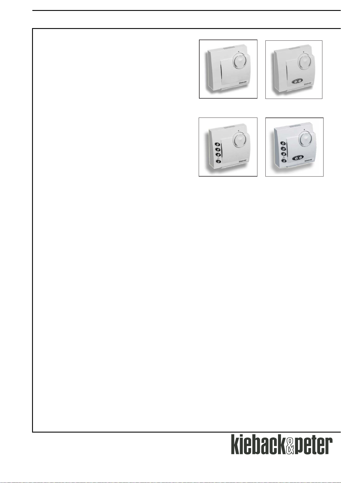
Types
TQF10 Room Service Module with a room
temperature sensor and the manual
adjustment of the room setpoint
TQF12 Room Service Module with a room
temperature sensor and the manual
adjustment of the room setpoint with
user button for switchover to day/night
TQF14 Room Service Module with a room
temperature sensor and the manual
adjustment of the room setpoint with user
button for the switching of three ventilator
speeds
TQF16 Room Service Module with a room
temperature sensor and the manual
adjustment of the room setpoint
with operating key for switchover to day/night
as well as the switching of three ventilator
speeds
®
Single room
TQF10
TQF12
TQF14
TQF16
Page 3 / 8
Technology for building automation
Page 4
Technical data sheet 1.10-51.010-01-en
TQF10, TQF12, TQF14, TQF16 Room Service Module Device Description
Technical data
Measured variable Room temperature in residential and office space
Measuring system Active measuring system KP10, 2.73 V at 0°C, TC 10 mV/C
Set value adjuster digital, regulating knob with trend arrow
Measuring range 0..45°C
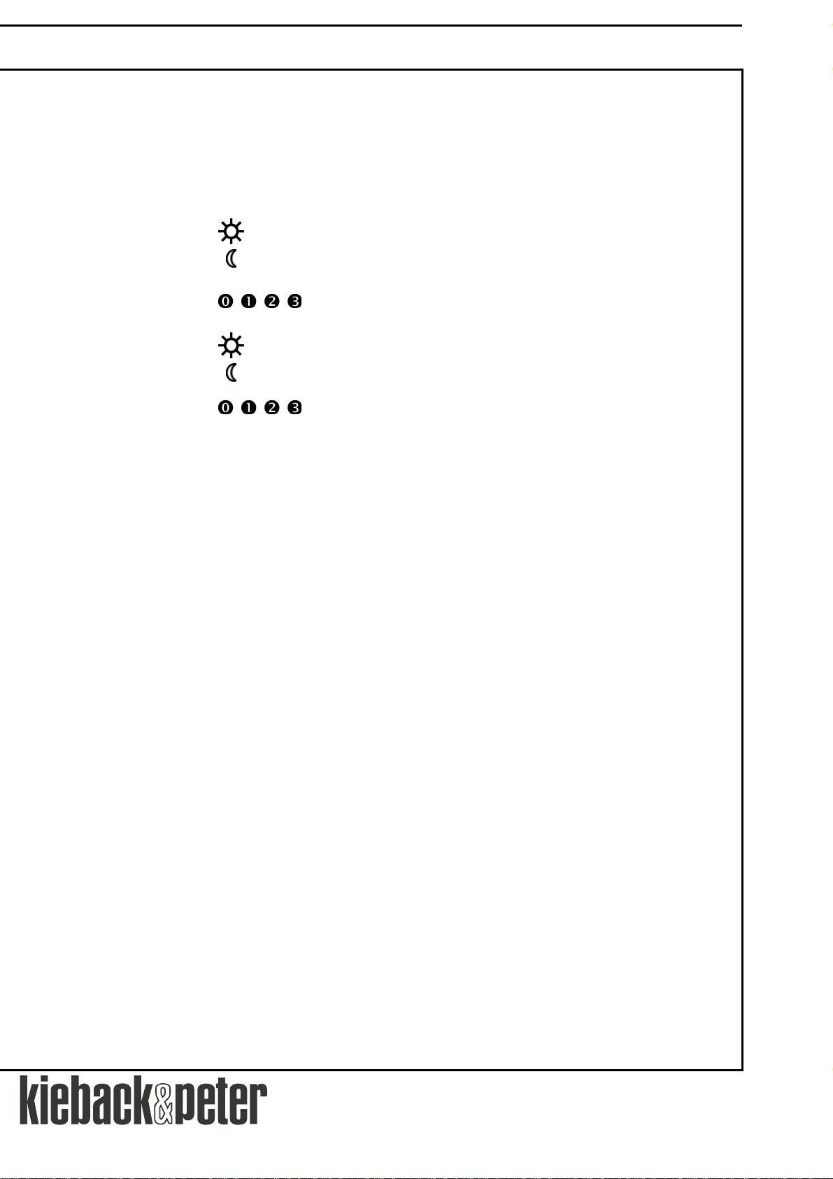
Control buttons
Key Switchover to night or lowering operation,
TQF14 Keys,
Key Switchover to night or lowering operation,
Keys,
Housing Hood, color RAL9010 (pure white)
Ambient conditions Temperature 0..45°C,
QB interface 4-conductor, for the connection of a technolon® Single room control FBR100-L,
protection
Dimensions Width x height x depth: 82.5 x 82.5 x 30 mm
Assembly Wall mounted/assembly in flush-mounted box
Weight 110 g
TQF12 Key Switchover to day operation, automatic for blower
TQF16
as well as automatic for ventilator
setting of the ventilator speeds off, level 1, level 2, level 3
Key Switchover to day operation, automatic for blower
as well as automatic for ventilator
setting of the ventilator speeds off, level 1, level 2, level 3
Backlighting of the keys depending on the configuration:
Steady burning light, on for 5 sec after keystroke or backlighting off
Humidity Non-condensing
line length max. 200m
IP30 Degree of enclosure
Technology for building automation
Page 4 / 8
Page 5
Technical data sheet 1.10-51.010-01-en
Device Description TQF10, TQF12, TQF14, TQF16 Room Service Module
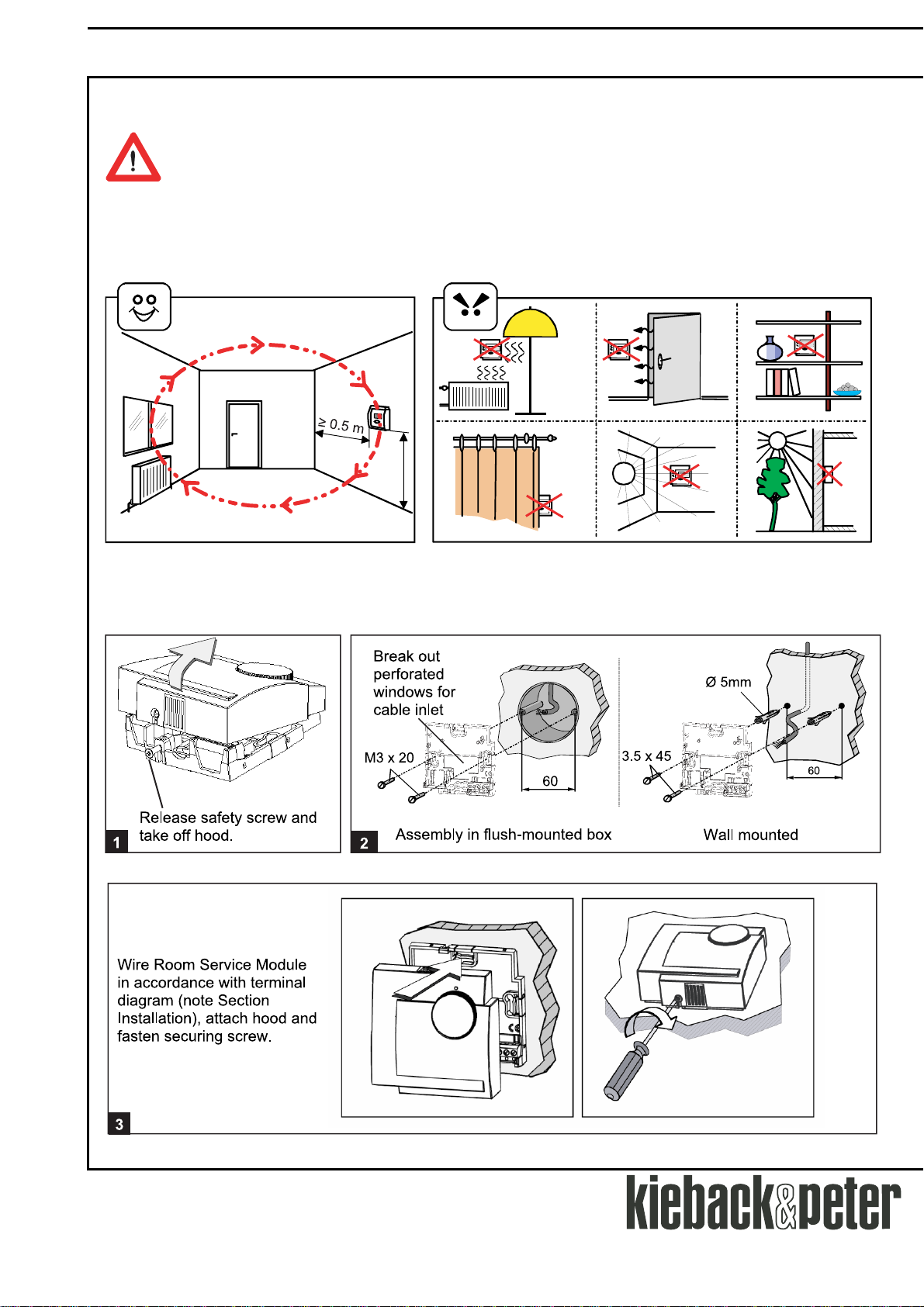
Assembly
The assembly may only be carried out by qualified personnel on voltage-free switched
connecting leads .
Warning The Room Service Modules TQF10, TQF12 and TQF16 can be assembled on the wall or in a flush-
mounted box.
For rapid and correct measurement of the room temperature, the Room Service Module is to be assembled in such
a way that the airflow of the room is included.
Airflow
correct
Assembly
1.5 m
false
Page 5 / 8
Technology for building automation
Page 6

Technical data sheet 1.10-51.010-01-en
TQF10, TQF12, TQF14, TQF16 Room Service Module Device Description
For surface-mounted or flush-mounted wiring, the hood and base have labeled housing parts that can be broken
out depending on the cable leads.
Furthermore, pluggable hood inserts are a part of the delivery which can be exchanged for the standard
inserts :
Note
C1/D1
C1
Inserts without air vents for greater wall influence.
D2
D1
D2
Inserts for cable inlet from below.
The device protection type IP30 is only guaranteed when the air
gap at the cable inlet is ≤ 2.5 millimeters.
Installation
The electrical installation and the Room Module connection may only be carried out by qualified
personnel.
Warning This must be done in accordance with the VDE regulations and local specifications.
Connection
TQF10
01PK
32 2931 30
27
TQF12
CD V0
ataD
12
C
D V21
klC
CD V0
01PK
ataD
12
32 2931 3027
C
D V21
klC
TQF14
01PK
32 2931 30
27
TQF16
CD V0
ataD
12
C
D V21
klC
01PK
322931 30
27
CD V0
ataD
12
C
D V21
klC
Technology for building automation
Page 6 / 8
Page 7

Technical data sheet 1.10-51.010-01-en
Device Description TQF10, TQF12, TQF14, TQF16 Room Service Module
Page 7 / 8
Technology for building automation
Page 8

Technical data sheet 1.10-51.010-01-en
TQF10, TQF12, TQF14, TQF16 Room Service Module Device Description
Technology for building automation
Page 8 / 8
 Loading...