

Kieback&Peter Technolon DDC110-L1, Technolon DDC110-L2, Technolon DDC110-L3, Technolon DDC110-L4 Technical Data Sheet
Page 1
Technical data sheet 1.10-51.110-81-en
j
g
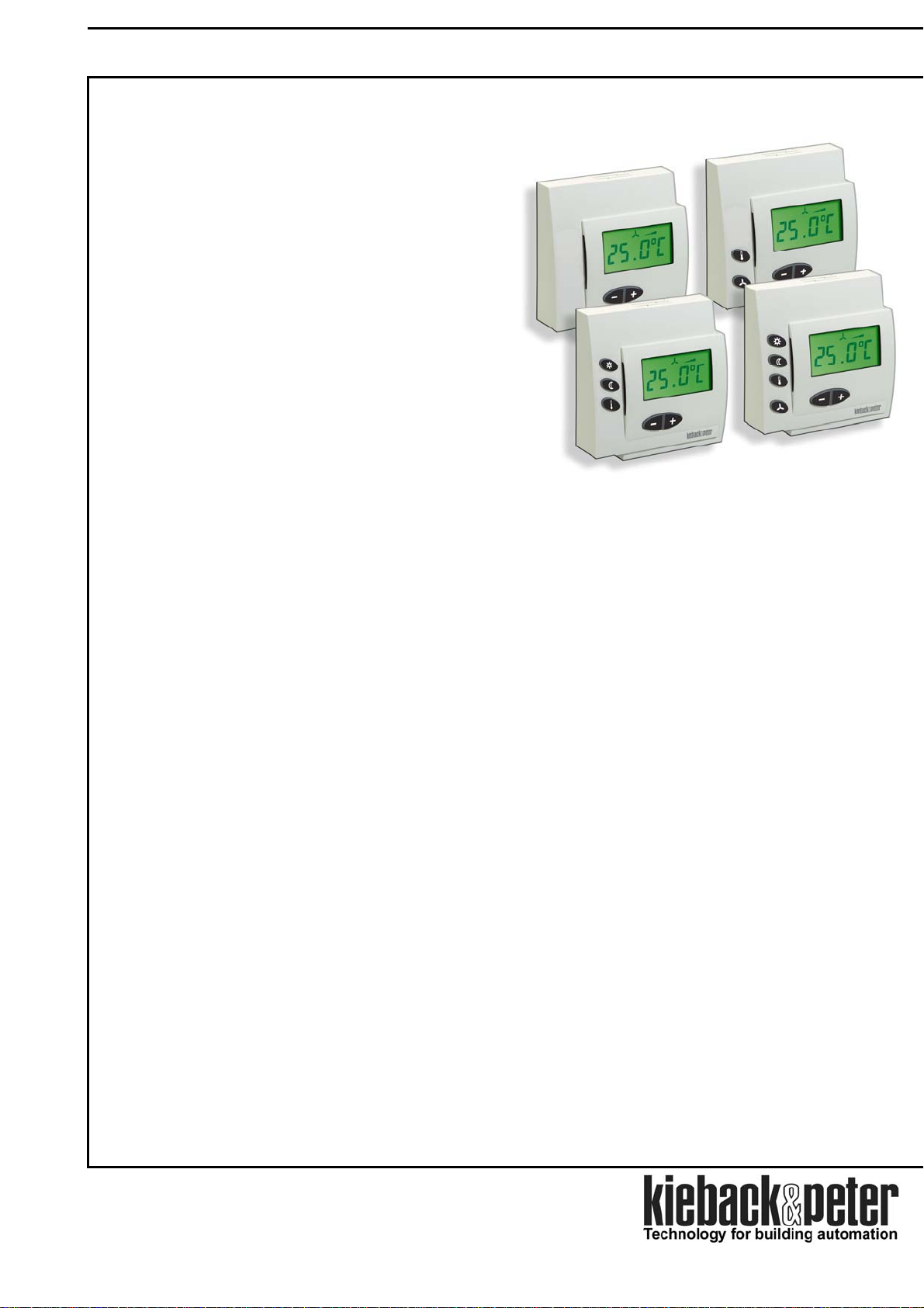
Device Description DDC110-L1 .. DDC110-L4 technolon® Room Module
technolon
DDC110-L2, DDC110-L3 and DDC110-L4
Single room control or room display and service
module for single-room control in the LON network.
With display of the room temperature and manual
adjustment of the room setpoint.
The DDC110-L2 technolon
additional user button for switching
3 ventilator speeds and temperature types.
The DDC110-L3 technolon
additionally has another user button for switching day
/night or standby operation and temperature type.
The DDC110-L4 technolon
DDC110-L3, additionally also has a user button for
switching 3 ventilator speeds.
With an I/O component (accessory), message inputs and servo devices
for heating and cooling as well as 3-level fan control can be directly
connected to a technolon
e
Contents
®
Room Module DDC110-L1,
®
Room Module has an
®
Room Module
®
Room Module, like
®
Room Module .
Notes on the device description
Page 2
Safety Instructions Page 2
Qualified specialists Page 2
ect to chan
Contents sub
Issue date: 02/10/2006
Kieback & Peter GmbH & Co KG
Tempelhofer Weg 50, D-12347 Berlin
Telephone +49 (0) 30 / 600 95-0
Telefax +49 (0) 30 / 600 95 164
E-Mail: info@kieback-peter.de
http://www.kieback-peter.de
Application Page 3
Types Page 3
Technical data Page 3
Operating Page 4
Assembly Page 10
Installation Page 12
Initial operation Page 12
Page 2
Technical data sheet 1.10-51.110-81-en
DDC110-L1 .. DDC110-L4 technolon® Room Module Device Description
Notes on the device description
The description contains references for the deployment and assembly of the technolon
®
Room Module.
In case of questions which cannot be clarified with this device description, please refer to the supplier or
manufacturer for further information.
The indicated installation instructions/regulations are valid in the Federal Republic of Germany.
When using the I/O components in other countries, the builder or operator of the plant is responsible for
compliance with the respective national regulations.
The operating staff is to be instructed in accordance with the description of the technical data sheet.
Safety Instructions
The currently valid worker’s occupational health regulations and regulations for the prevention of industrial
accidents must be observed when assembling and using the devices.
Any work concerning the installation or initial operation of the control devices shall be exclusively carried out by
qualified specialists, see section “Qualified specialists”.
Every person using the devices shall have read and understood the descriptions in the technical data sheet.
If the equipment is not used according to the technical data sheet, the protection might be lower as stated.
Meaning of the symbols in the technical data sheet:
Warning of dangerous electrical voltage
Danger
General warning, strictly observe this notice
Warning
Note
Danger
Further notice to observe
means mortal danger, severe bodily injuries or serious material damage in case of
non-observance.
Warning
Note
means danger of bodily injuries or material damage in case of non-observance.
indicates information which is particularly emphasized.
Qualified specialists
Qualified specialists for the purposes set out in this technical data sheet are persons who are familiar with the described
devices and possess a qualification for their respective occupation.
These are for instance:
• Authorization to connect the devices according to the VDE rules and local Electricity Board regulations, as
well as the authorization to switch the devices on and off taking the in-house regulations into account.
• Knowledge of the regulations for the prevention of industrial accidents.
• Knowledge of the utilization of the devices within the plant system.
• etc.
Page 2 / 12
Page 3
Technical data sheet 1.10-51.110-81-en
Device Description DDC110-L1 .. DDC110-L4 technolon® Room Module
Application
The technolon
DDC110-L3 and DDC110-L4 are employed in the singleroom control of the LON network as Single Room Control
or as room displays and service modules .
An I/O component UP can be connected at the
Room Module as an accessory. The I/O component
provides the direct connection of a presence
detector and a window contact or dew-point detector,
the direct connection of the heating and cooling
circuit as well as the activation of 3-level ventilators.
The I/O component is installed in a double flushmounted box.
Types
DDC110-L1 technolon
DDC110-L2 technolon
DDC110-L3 technolon
DDC110-L4 technolon
Accessories I/O componenets
UP1 2 Digital inputs for the connection of the window contact/dew-point detector and presence
2 Thyristor switching outputs 24 V AC, 1 A (1 x heating, 1 x cooling)
UP2 like UP1, however additionally
3 Relay outputs 250 V AC, 6 A (3-level fan control)
UP3 2 Digital inputs for the connection of the window contact/dew-point detector and presence
2 analog outputs 0..10 V DC, 10 mA (1 x heating, 1 x cooling)
UP4 like UP1, however additionally
3 Relay outputs 250 V AC, 6 A (3-level fan control)
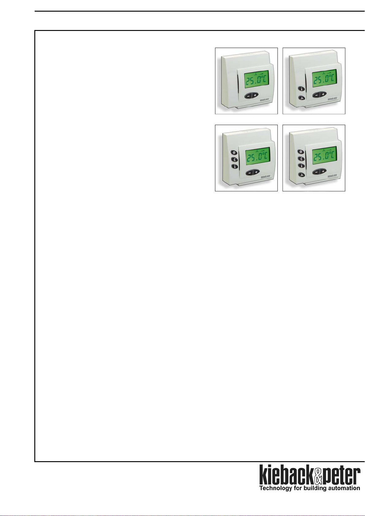
®
Room Modules DDC110-L1, DDC110-L2,
®
Room Module with
display of the room temperature
and manual adjustment of the
room setpoint.
®
Room Module with
display of the room temperature
and manual adjustment of the
room setpoint as well as switching
of three ventilator speeds.
®
Room Module with display of
the room temperature and manual
adjustment of the room setpoint as well
as switchover to
day /night or standby operation
®
Raummodul with
display of the room temperature
and manual adjustment of the
room setpoint as well as
switchover to day /night or
standby operation
detector
detector
DDC110-L1
DDC110-L3
DDC110-L2
DDC110-L4
Page 3 / 12
Page 4
Technical data sheet 1.10-51.110-81-en
DDC110-L1 .. DDC110-L4 technolon® Room Module Device Description
Technical data – Room Module DDC110-L1 to DDC110-L4
Mains 24 V AC/DC ± 10 %, 10 mA (without I/O component UP)
Bus connection - LON FTT10
Application: According to LONMARK standard:
LONMARK profile #8060 for single room control or
LONMARK profile #8090 for room display and service module
- Bus for I/O component UP on plug contact
Measured variable Room temperature in residential and office space
Measuring system integrated digital room sensor
Measuring range 0..45°C
Connection Terminal connection, max, 2.5 mm
Display LCD display
- Rough measured value 0..45.0°C, resolution 0.1 K
- Room setpoint 0..45.0°C, resolution 0.1 K
- Display icon for operating modes
Control buttons DDC110-L1
DDC110-L2
Key, control setting of the room temperature
Key, switchover to temperature type for setting the room setpoint
Key, switchover to ventilator modules for manual switching of the
ventilator speeds
Key, setting the room setpoint or manual switching of the ventilator
speeds backlighting of the keys
configuration:
Steady burning light, on for 5 sec after keystroke, or backlighting off
DDC110-L3
Key, switchover to day operation
Key, switchover to night or standby operation
Key, switchover to temperature type for setting the room setpoint
Backlighting of the keys
Steady burning light, on for 5 sec after keystroke or backlighting off
DDC110-L4
Key, switchover to day operation
Key, switchover to night or standby operation
Key, switchover to temperature type for setting the room setpoint
Key, switchover to ventilator modules for manual switching of the
ventilator speeds
Key, switchover to ventilator modules for manual switching of the
ventilator speeds
Key, setting the room setpoint or manual switching of the ventilator
speeds
Backlighting of the keys
configuration:
Steady burning light, on for 5 sec after keystroke or backlighting off
Housing Hood, color RAL9010 (pure white)
Special colors upon request
Temperature 0..45°C, Ambient conditions
Humidity not condensing
Degree of enclosure
IP30
protection
Dimensions Width x height x depth: 82.5 x 82.5 x 30 mm
Assembly Wall mounted/assembly in flush-mounted box
Weight 110 g
2
depending on the
depending on the configuration:
depending on the
Page 4 / 12
Page 5

Technical data sheet 1.10-51.110-81-en
Device Description DDC110-L1 .. DDC110-L4 technolon® Room Module
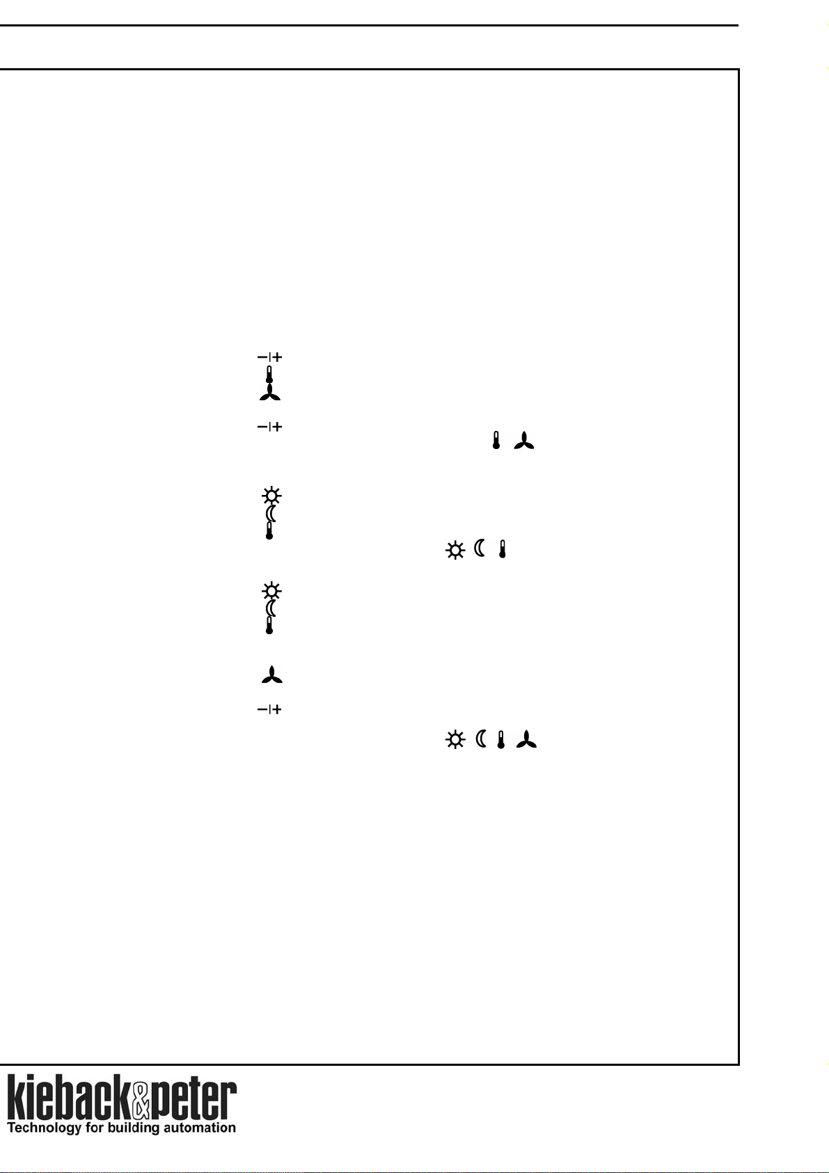
Operation DDC110-L1
Display depending on the configuration:
Room temperature (actual value) with function symbol
or
Room setpoint with function symbol
↕
Other function symbols can be displayed depending on the
configuration:
Day operation
Night operation
Standby operation
Automatic switchover by
Central Program or presence
detector
Function symbols
Digital readout
Room setpoint selection
►
The room setpoint for day, night or standby operation is automatically determined by the program.
Depending on the configuration release, the room setpoint can be raised or lowered by ± 3 K or ± 5 K by manual
adjustment.
The manual adjustment acts as setpoint correction for all operating modes alike:
Example: If the current room setpoint day is raised by 2 K,
then the room setpoint night and the room setpoint standby are raised by 2 K .
Key
Simultaneously, the decimal place of the current control setting blinks .
Now the room setpoint can be increased or lowered with the key in steps of 0.1 K .
Press once : The Room Module switches to temperature type control setting.
Function symbols
↕ or ↕ or ↕ are displayed,
Without pressing a key, the Room Module switches back to the standard after 5 sec display .
The new room setpoint is stored.
Page 5 / 12
Page 6

Technical data sheet 1.10-51.110-81-en
DDC110-L1 .. DDC110-L4 technolon® Room Module Device Description
Operation DDC110-L2
Display depending on the configuration:
Room temperature (actual value) with function symbol
or
Room setpoint with function symbol
↕
Other function symbols can be displayed depending on the
configuration:
Day operation
Night operation
Standby operation
Automatic switchover by
Central Program or presence
detector
Function symbols
Digital readout
Room setpoint selection
►
The room setpoint for day, night or standby operation is automatically determined by the program.
Depending on the configuration release, the room setpoint can be raised or lowered by ± 3 K or ± 5 K by
manual adjustment.
The manual adjustment acts as setpoint correction for all operating modes alike:
Example: If the current room setpoint day is raised by 2 K,
then the room setpoint night and the room setpoint standby are raised by 2 K .
Key
Simultaneously, the decimal place of the current control setting blinks .
Press once : The Room Module switches to temperature type control setting.
Function symbols
↕ or ↕ or ↕ are displayed,
Now the room setpoint can be increased or lowered with the key in steps of 0.1 K .
With the key
, it is immediately possible to switch back to the standard display.
Without pressing a key, the Room Module switches back to the standard after 5 sec
Switching ventilator speeds on and off
►
display . The new room setpoint is stored.
The ventilator speeds are automatically switched on and off by the program .
If required, the ventilator speeds can be switched by manual control.
Key
Simultaneously, the current ventilator setting blinks 0, 1, 2, 3 or auto.
and the Room Module switches to ventilator mode for manual control.
Function symbol
is displayed,
0 Ventilator off, No function symbol
1
2
3
Auto
Ventilator level 1
on
Ventilator level 2
on
Ventilator level 3
on
Automatic
operation:
Function symbol
Function symbol
Function symbol
Function symbol
lights up in seconds beat
The new ventilator level is set with the key
With the key
, it is immediately possible to switch back to the standard display.
.
Without pressing a key, the Room Module switches back to the standard after 5 sec
display . The new room setpoint is stored.
Page 6 / 12
Page 7

Technical data sheet 1.10-51.110-81-en
Device Description DDC110-L1 .. DDC110-L4 technolon® Room Module
Operation DDC110-L3
Display depending on the configuration:
Room temperature (actual value) with function symbol
or
Room setpoint with function symbol
↕
Other function symbols can be displayed depending on the
configuration:
Day operation
Night operation
Standby operation
Automatic switchover by
Central Program or presence
detector
Function symbols
Digital readout
Room setpoint selection
►
The room setpoint for day, night or standby operation is automatically determined by the program.
Depending on the configuration release, the room setpoint can be raised or lowered by ± 3 K or ± 5 K by manual
adjustment.
The manual adjustment acts as setpoint correction for all operating modes alike:
Example: If the current room setpoint day is raised by 2 K,
then the room setpoint night and the room setpoint standby are raised by 2 K .
Key
Simultaneously, the decimal place of the current control setting blinks .
Now the room setpoint can be increased or lowered with the key in steps of 0.1 K .
Press once : The Room Module switches to temperature type control setting.
Function symbols
↕ or ↕ or ↕ are displayed,
Without pressing a key, the Room Module switches back to the standard after 5 sec
Switch on day or standby operation
►
display . The new room setpoint is stored.
The night or standby operation is automatically switched on or off by the Central Program.
The day operation is switched on by the presence detector or manually with the key
Switch on day operation
.
The day operation can only be switched on manually in the operation mode night or standby .
For the manual switching of night to day operation, the day operation
is switched on only for a time period
determined by the program .
After expiration of this time, the Room Module switches back to night operation.
Switch on day operation
Press key
, function symbol is displayed.
When switching over from night to day operation, the time period for switched on
day operation is displayed for 5 sec.
Standby operation
The standby operation can be switched on by a presence detector or manually only in the daytime operation
mode, e.g. upon vacating the room.
Standby operation
Press key
, function symbol is displayed.
The key
switches off the standby operation again .
Page 7 / 12
Page 8

Technical data sheet 1.10-51.110-81-en
DDC110-L1 .. DDC110-L4 technolon® Room Module Device Description
Operation DDC110-L4
Display depending on the configuration:
Room temperature (actual value) with function symbol
or
Room setpoint with function symbol
↕
Other function symbols can be displayed depending on the
configuration:
Day operation
Night operation
Standby operation
Automatic switchover by
Central Program or presence
detector
Function symbols
Digital readout
Room setpoint selection
►
The room setpoint for day, night or standby operation is automatically determined by the program.
Depending on the configuration release, the room setpoint can be raised or lowered by ± 3 K or ± 5 K by
manual adjustment.
The manual adjustment acts as setpoint correction for all operating modes alike:
Example: If the current room setpoint day is raised by 2 K,
then the room setpoint night and the room setpoint standby are raised by 2 K .
Key
Simultaneously, the decimal place of the current control setting blinks .
Press once : The Room Module switches to temperature type control setting.
Function symbols
↕ or ↕ or ↕ are displayed,
Now the room setpoint can be increased or lowered with the key in steps of 0.1 K .
With the key
, it is immediately possible to switch back to the standard display.
Without pressing a key, the Room Module switches back to the standard after 5 sec
Switch on day or standby operation
►
display . The new room setpoint is stored.
The night or standby operation is automatically switched on or off by the Central Program.
The day operation is switched on by the presence detector or manually with the key
Switch on day operation
.
The day operation can only be switched on manually in the operation mode night or standby .
For the manual switching of night
to day operation, the day operation is switched on only for a time period
determined by the program .
After expiration of this time, the Room Module switches back to night operation.
Switch on day operation
Press key
, function symbol is displayed.
When switching over from night to day operation, the time period for switched on
day operation is displayed for 5 sec.
Standby operation
The standby operation can be switched on by a presence detector or manually only in the daytime operation
mode, e.g. upon vacating the room.
Standby operation
Press key
, function symbol is displayed.
The key
switches off the standby operation again .
Page 8 / 12
Page 9

Technical data sheet 1.10-51.110-81-en
Device Description DDC110-L1 .. DDC110-L4 technolon® Room Module
Switching ventilator speeds on and off
►
The ventilator speeds are automatically switched on and off by the program .
If required, the ventilator speeds can be switched by manual control.
Key
Simultaneously, the current ventilator setting blinks 0, 1, 2, 3 or auto.
0 Ventilator off, No function symbol
The new ventilator level is set with the key
Without pressing a key, the Room Module switches back to the standard after 5 sec
and the Room Module switches to ventilator mode for manual control.
Function symbol
1
2
3
Auto
Ventilator level 1
on
Ventilator level 2
on
Ventilator level 3
on
Automatic
operation:
is displayed,
Function symbol
Function symbol
Function symbol
Function symbol
lights up in seconds beat
.
With the key
, it is immediately possible to switch back to the standard display.
display . The new room setpoint is stored.
Page 9 / 12
Page 10

Technical data sheet 1.10-51.110-81-en
DDC110-L1 .. DDC110-L4 technolon® Room Module Device Description
Assembly
The assembly may only be carried out by qualified personnel on voltage-fee switched
connecting leads .
Warning The Room Module can be mounted in the wall or in a flush-mounted box.
For rapid and correct measurement of the room temperature, the Room Module is to be assembled in
such a way that the airflow of the room is included.
Airflow
,1m 5
correct
Assembly
false
Page 10 / 12
Page 11

Technical data sheet 1.10-51.110-81-en
Device Description DDC110-L1 .. DDC110-L4 technolon® Room Module
3
Attach hood and tighten securing screw
For surface-mounted or flush-mounted wiring, the hood and base have labelled housing parts that can be broken out
depending on the cable leads.
Furthermore, pluggable hood inserts are a part of the delivery which can be exchanged for the standard
inserts :
Note
C1/D1 Inserts for higher air throughput.
accessory kit with additional
inserts for the hood
C1
D2 Inserts for cable inlet from below.
D1 D2
The device protection type IP30 is only guaranteed when the
air gap at the cable inlet is ≤ 2.5 millimeters.
Page 11 / 12
In the building phase, the carton box serves
as protective cover.
Please tear off the box top and depress side straps to the
inside .
Page 12

Technical data sheet 1.10-51.110-81-en
DDC110-L1 .. DDC110-L4 technolon® Room Module Device Description
Installation
The electrical installation and the Room Module connection may only be carried out by qualified
personnel.
Warning This must be done in accordance with the VDE regulations and local specifications.
Connection
DDC110-L..
1181920
24 V AC/DC
0 V AC/DC
Mains
LON-Bus
A
B
The bus connection lines
Clamps 1/20 are
mutually exchangeable.
Warning: Supply voltage 230 V for use of I/O components UP2 or UP4!
Note without fail the technical device manual in the Technical Data Sheet 1.10-51.110-91 !
Danger
The I/O component UP with inputs and outputs can be connected at the Room Module .
Room Module and I/O component form a device unit.
The I/O component is employed in a double flush-mounted box with a depth of at least 60 millimeters,
the Room Module is mounted on the flush-mounted box.
The connection between the Room Module and the I/O component UP is carried out on the 5-line
bus line of the I/O component which is connected with a socket plug on the Room Module .
Initial operation
Warning! Warning: Supply voltage 230 V for use of I/O components UP2 or UP4!
Initial startup by switching on the supply voltage may only take place after the configuration
setting and connection testing of the Room Module by the startup technician/engineer.
Danger
– the electric wiring acc. to VDE (Association of German electrotechnicians) regulations and the
te correct mounting location for recording the room temperature,
the competent assembly as well as
the permissible ambient conditions according to the technical data.
the total function of the Room Module (if necessary. including I/O component UP)
• Before mains network has been switched on, check
local regulations,
• The Room Module is configured as a single room control or as display and service module with the
parameter settingson a network management tool (e.g. LonMaker) with the service PC.
• After the network is switched on, check
with the plant components of the room control loop.
Page 12 / 12
 Loading...