

Page 1
Issue 2014-11-19
Datasheet 2.50-40.151-11-EN
Product Description
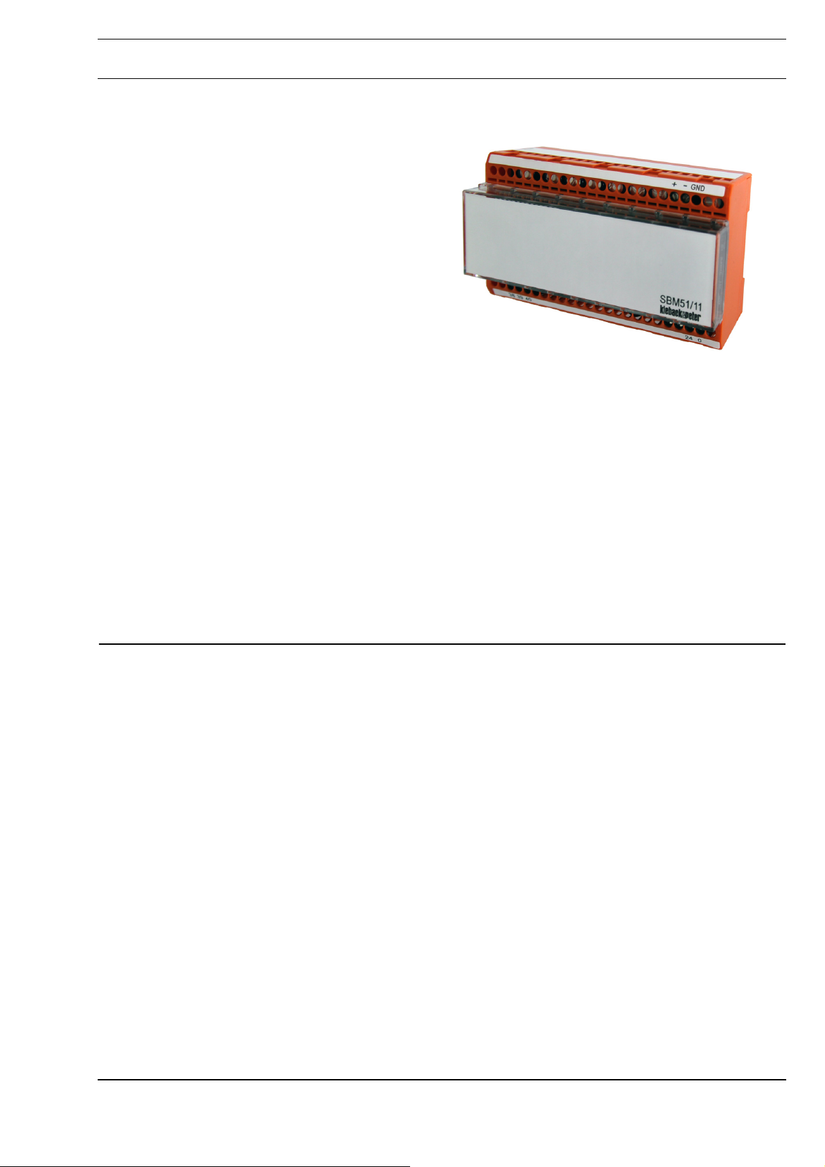
SBM51/11 Switch cabinet bus module
for energy monitoring devices A210/A220 and
A230/A230s with communication module EMMOD
201 from the company Camille Bauer
Application
The switch cabinet bus module SBM51/11 is used to
integrate up to 8 energy monitoring devices into the
DDC3000 or DDC4000 system via Modbus RTU.
SBM51/11
Content Page
Important Information Regarding Product Safety ..................................................................................................2
Item........................................................................................................................................................................3
Technical Data.....................................................................................................................................................3
Dimensions..........................................................................................................................................................3
Connection...........................................................................................................................................................4
Mounting ................................................................................................................................................................5
Removal.................................................................................................................................................................5
Commissioning ......................................................................................................................................................6
Indicators and Controls........................................................................................................................................6
Setting the switch cabinet bus address ...............................................................................................................7
Description of Parameters .....................................................................................................................................8
Parameter List in the DDC3000 System..............................................................................................................8
Parameter List in the DDC4000 System..............................................................................................................8
Assignment of Software Menus / System Objects to the Energy Monitoring Devices.........................................9
Parameter Settings for the Energy Monitoring Devices.......................................................................................9
Points Lists ........................................................................................................................................................11
Reference Lists for Parameters according to Connection Type ........................................................................15
Änderungen vorbehalten - Contents subject to change - Sous réserve de modifications - Reservado el derecho a modificación - Wijzigingen
voorbehouden - Con riserva di modifiche - Innehåll som skall ändras - Zmeny vyhradené - Změny vyhrazeny - Zmiany zastrzeżone - Возможны
изменения - A változtatások jogát fenntartjuk - ֱ⬭㒣䗮ⶹ㗠ᬍࡼⱘᴗ
Kieback&Peter GmbH & Co. KG
Tempelhofer Weg 50, 12347 Berlin/Germany
Telefon: +49 30 60095-0, Telefax: +49 30 60095-164
www.kieback-peter.de, info@kieback-peter.com
A
Page 2
Datasheet 2.50-40.151-11-EN Issue 2014-11-19
Product DescriptionSBM51/11
Important Information Regarding Product Safety
Safety Instructions
This data sheet contains information on installing and commissioning the product "SBM51/11". Each
person who carries out work on this product must have read and understood this data sheet. If you
have any questions that are not resolved by this data sheet, you can obtain further information from
the supplier or manufacturer.
If the product is not used in accordance with this data sheet, the protection provided will be impaired.
Applicable regulations must be observed when installing and using the device. Within the EU, these
include regulations regarding occupational safety and accident prevention as well as those from the
VDE (Association for Electrical, Electronic & Information Technologies). If the device is used in other
countries, it is the responsibility of the system installer or operator to comply with local regulations.
Mounting, installation and commissioning work on the devices may only be carried out by qualified
technicians. Qualified technicians are persons who are familiar with the described product and who
can assess given tasks and recognize possible dangers due to technical training, knowledge and
experience as well as knowledge of the appropriate regulations.
Legend
WARNING
Indicates a hazard of medium risk which can result in death or severe bodily injury if it is not avoided.
!
CAUTION
Indicates a hazard of low risk which can result in minor or medium bodily injury if it is not avoided.
CAUTION
Indicates a hazard of medium risk which can result in material damage or malfunctions if it is not
avoided.
NOTE
Indicates additional information that can simplify the work with the product for you.
Notes on Disposal
For disposal, the product is considered waste from electrical and electronic equipment (electronic
waste) and must not be disposed of as household waste. Special treatment for specific components
may be legally binding or ecologically sensible. The local and currently applicable legislation must be
observed.
A
Page 2 / 16
Page 3
Issue 2014-11-19
Item
SBM51/11 Switch cabinet bus module with Modbus input for a maximum of 8 energy
Technical Data
Nominal voltage ■ For device: AC 24 V ±10% / 230 mA, max. 5.4 VA
Fuse Electronic fuse protection for AC 24 V power
Indicators and controls
Interfaces
Overvoltage category III
Rated impulse voltage 800 V
Level of contamination 2
Automatic action Type 1
Degree of protection IP20
Ambient temperature 0% to 45 °C
Ambient humidity 20% to 80% r.h.; non-condensing
Installation Switch cabinet installed on top hat rail DIN EN 50022 – 35 x 7.5
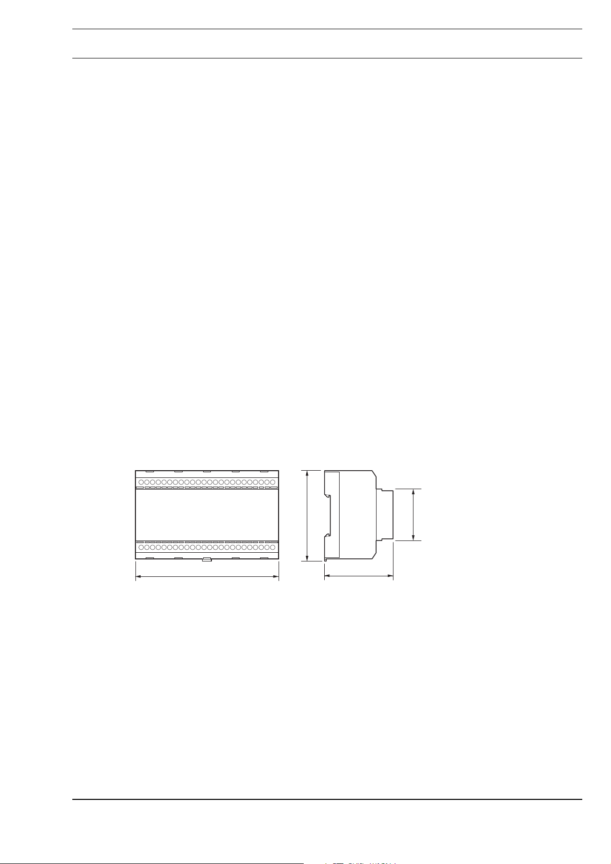
Dimensions
(WxHxD in mm)
Datasheet 2.50-40.151-11-EN
SBM51/11Product Description
monitoring devices
■ 2 LEDs in housing
■ 2 rotary switches in housing, for setting the switch cabinet bus address
■ Switch cabinet bus to DDC system
■ Serial interface/RS485 bus (Modbus RTU)
125 x 77 x 60
Dimensions
125,0
77,0
44,7
60,0
Page 3 / 16
A
Page 4
Datasheet 2.50-40.151-11-EN Issue 2014-11-19
Product DescriptionSBM51/11
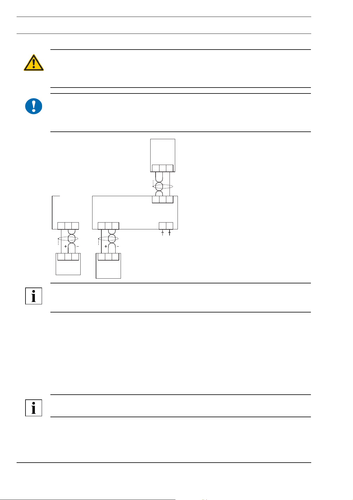
Connection
WARNING
Contact with live parts of electrical domestic installation can cause death due to electric shock.
Only connect the device and switch on the power supply if you are qualified to do so. Be sure to
comply with VDE guidelines and local wiring regulations.
CAUTION
!
Switching on the power supply of unparameterized products can lead to unforeseen consequences
such as malfunctions or material damage.
Switch on the power only after the device has been configured by the commissioning technician.
Camille
Bauer
EMMOD 201
GND
–
+
30
31 32
GND
–
+
RS485
38
39 40
18 19 20
System
DDC4000
38
39 40
38 39 40
System
DDC3000
DDC4000
24 0
24V~
0V~
NOTE
The bus systems of the switch cabinet bus (DDC3000) and the CAN bus (DDC4000) are identical.
Accordingly, the technical information for the switch cabinet bus also applies to the CAN bus.
Switch cabinet bus
When connecting the switch cabinet bus, use a cable of at least type JY(St)Y 2x2x0.8 Lg: two x two
leads stranded into a pair, plastic insulation and an electrostatic shield with a lead diameter of at least
0.8 mm. Use a stranded pair of leads for the data lines (+ and -) and another free lead for the
ground (0).
At the end of the switch cabinet bus (farthest point from the DDC controller), install a terminating
resistor of about 180 ohms between both data lines (+ and -). The terminating resistor is included with
the DDC controller
The maximum cable length for the switch cabinet bus is 200 m.
NOTE
The DDC3000 / DDC4000 system already includes terminating resistors.
Modbus
Modbus RTU is used as the protocol for the foreign bus connection.
A
Page 4 / 16
Page 5
Issue 2014-11-19
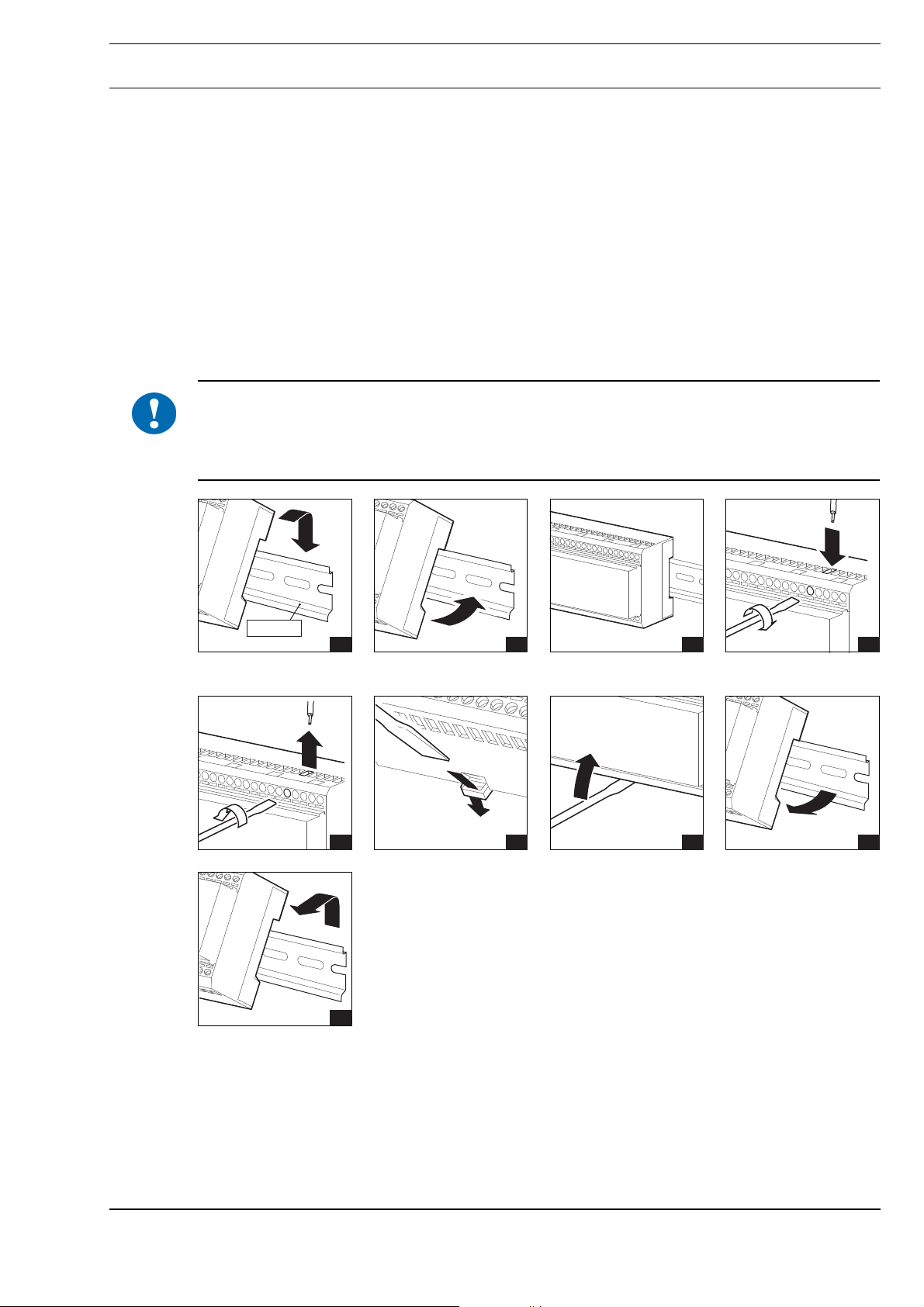
Mounting
!
Datasheet 2.50-40.151-11-EN
SBM51/11Product Description
When connecting the third-party devices, use a cable of at least type JY(St)Y 2x2x0.8 Lg: two leads
stranded into a pair, with plastic insulation and an electrostatic shield with a lead diameter of at least
0.8 mm. Use a stranded pair of leads for the data lines (+ and -).
The maximum cable length for the Modbus is 1000 m.
The SBM51/11 uses the following interface parameters:
■ Baud rate: 9600 baud
■ Data bits: 8
■ Stop bit: 1
■ Parity: even
The energy monitoring devices must use the same settings. These parameters can be entered
directly on the energy monitoring device.
CAUTION
Switching on the power supply of unparameterized products can lead to unforeseen consequences
such as malfunctions or material damage.
Switch on the power only after the device has been configured by the commissioning technician.
Removal
TH 35-7.5
1 2 3 4
1 2 3 4
5
Page 5 / 16
A
Page 6

Datasheet 2.50-40.151-11-EN Issue 2014-11-19
Product DescriptionSBM51/11
Commissioning
CAUTION
!
Indicators and Controls
Power may only be switched on after the DDC controller and device have been configured by the
commissioning technician.
Configuration of the DDC controller is described in the respective project planning documentation.
12
1 Rotary switch for setting the switch cabinet bus address
2 Switch cabinet bus LED
LED Signal Meaning
Switch cabinet bus LED Green SBM51/11 is operating
Switch cabinet bus LED Flashing green Data transmission
Switch cabinet bus LED Red Switch cabinet bus error
Switch cabinet bus LED Flashing red Incorrect or duplicate address
A
Page 6 / 16
Page 7

Issue 2014-11-19
Setting the switch cabinet bus address
► Disconnect the power supply of the SBM51/11.
► Press the lower edge of the front
cover and remove the cover.
The rotary switches for setting the switch
cabinet bus address are located inside
the SBM51/11.
Datasheet 2.50-40.151-11-EN
SBM51/11Product Description
► Set the first rotary switch to the first
digit of the switch cabinet bus
address, and the second rotary
switch to the second digit.
The example shows the address “15”.
Permitted range for the switch cabinet
bus address: 01 to 16
► Insert the front damper along the top
edge and lock it in with the bottom
edge.
► Reconnect the power supply of the SBM51/11.
0
6
5
0
9
1
8
2
3
7
4
6
5
x 10 x 1
1
2
3
4
Page 7 / 16
A
Page 8

Datasheet 2.50-40.151-11-EN Issue 2014-11-19
Product DescriptionSBM51/11
Description of Parameters
Parameter List in the DDC3000 System
Parameter 2202 "Q Bus Mode"
Parameter 2202 turns the communication for the bus system (Modbus) on or off:
■ "0" Modbus OFF
■ "1" Modbus ON
Parameter 2203 "Q cycle"
Parameter 2203 defines the cycle time for reading the energy monitoring devices:
■ "0" The SBM51/11 reads the energy monitoring devices continuously.
■ "1" The SBM51/11 reads the energy monitoring devices every minute.
NOTE
When you change the value from "0" to "1", the SBM51/11 immediately reads all energy monitoring
devices on Modbus. You can use this function to trigger a readout of all energy monitoring devices
on Modbus.
Parameter 2204 "Foreign bus OK"
Parameter 2204 reports malfunctions on Modbus to the SBM51/11:
■ "1" Modbus is working without errors.
■ "0" Errors occurred on Modbus.
Parameter List in the DDC4000 System
Enable parameter: "Enable bus"
The Enable parameter turns the communication for the bus system (Modbus) on or off:
■ "0" Modbus OFF
■ "1" Modbus ON
Cycle parameter: "Readout cycle"
The Cycle parameter defines the cycle time for reading the energy monitoring devices:
■ "0" The SBM51/11 reads the energy monitoring devices continuously.
■ "1" The SBM51/11 reads the energy monitoring devices every minute.
NOTE
When you change the value from "0" to "1", the SBM51/11 immediately reads all energy monitoring
devices on Modbus. You can use this function to trigger a readout of all energy monitoring devices
on Modbus.
Active parameter
The Active parameter reports malfunctions on Modbus to the SBM51/11:
■ "1" Modbus is working without errors.
■ "0" Errors occurred on Modbus.
A
Page 8 / 16
Page 9

Issue 2014-11-19
Assignment of Software Menus / System Objects to the Energy Monitoring Devices
DDC3000 DDC4000
Energy monitoring device
1 1 1 H000.01
2 1 5 H000.05
... Repeating Consecutive Consecutive
8 1 29 H000.29
Phase
2 2 H000.02
3 3 H000.03
Totals menu 4 H000.04
2 6 H000.06
3 7 H000.07
Totals menu 8 H000.08
2 30 H000.30
3 31 H000.31
Totals menu 32 H000.32
Software menu
M090 SBM 51
System object
"H000"
Datasheet 2.50-40.151-11-EN
SBM51/11Product Description
Parameter Settings for the Energy Monitoring Devices
Parameter 2209 "External building complex malfunction"
Parameter 2209 shows the status of a device for the menu group.
DDC4000: Active parameter in system object H000.xx.
■ "0" Device present
■ "1" Device not present
Parameter 2215 (totals menu) - Adjustment frequency
Parameter 2215 shows the adjustment frequency. Possible display values are:
■ 16 2/3 Hz (displayed as 16)
■ 50 Hz
■ 60 Hz
■ 400 Hz
Parameter 2215 is only available for energy monitoring devices A230/A230s.
Parameter 2220 (totals menu) - Set display of performance values (parameters 2254, 2255,
2256)
Parameter 2220 sets the display of the performance values for parameters 2254, 2255, 2256 within
the software menu group.
■ "deleted" (--) or "0" Energy in kWh, kVAh, kVArh
■ "1" Energy in Wh, VAh, VArh
Page 9 / 16
Parameter 2245 (totals menu) - Set display of energy values
Parameter 2245 sets the display of the energy values for parameters 2212, 2251, 2215 and 2252
(phase menu L1 and L2) within the software menu group.
■ "deleted" (--) or "0" Performance in kW, kVA, kVAr
■ "1" Performance in W, VA, VAr
A
Page 10

Datasheet 2.50-40.151-11-EN Issue 2014-11-19
Product DescriptionSBM51/11
Parameter 2251 (totals menu) - Connection type
Parameter 2251 shows the connection type. Possible values and their meaning are listed here:
■ "0" - Single phase system
■ "1" - Three-wire three-phase system, balanced load
■ "2" - Four-wire three-phase system, balanced load
■ "3" - Three-wire three-phase system, unbalanced load, Aron wiring
■ "4" - Four-wire three-phase system, unbalanced load
■ "19" - Three-wire three-phase system, unbalanced load
■ "20" - Four-wire three-phase system, unbalanced load (Open Y)
Depending on the connection type, different parameters are available in the phase menus and in the
totals menu. See chapter “Reference Lists for Parameters according to Connection Type”, page 15.
Parameter 2246 (totals menu) - Rate settings
You can change rates using parameter 2246 or using the digital input on the energy monitoring
device. The rate that currently applies is displayed in parameter 2225 (totals menu).
If the digital input on the energy monitoring device is used for changing the rate, parameter "2246"
must be set to "invalid".
■ Parameter 2246 = "0" High rate
■ Parameter 2246 = "1" Low rate
Parameter 2240 (totals menu) and parameter 2216 (totals menu) - Addressing of the energy
monitoring devices
■ Parameter 2240 = "0" The corresponding device is not read.
If addresses 1 to 8 are used for the energy monitoring devices, then the devices are automatically
recorded. See chapter “Assignment of Software Menus / System Objects to the Energy Monitoring
Devices”, page 9.
Parameter 2216 (totals menu) must contain the value "0".
If different device addresses are to be used, then enter the device addresses (1 to 247) of the energy
monitoring devices in parameter 2240 of the respective totals menu.
Parameter 2216 (totals menu) must contain the value "1".
■ Parameter 2216 = "0" Standard address (1 to 8)
■ Parameter 2216 = "1" Read address from parameter 2240 (1-247)
A
Page 10 / 16
Page 11

Issue 2014-11-19
Points Lists
Datasheet 2.50-40.151-11-EN
SBM51/11Product Description
Phase menu L1
DDC3000: M090 SBM51 Gateway
DDC4000: CD_SB51
Parameter
name
2209 External building com-
2210 Analog actual value 1 Delta voltage U12 V
2211 Analog actual value 2 Phase voltage U1 V
2212 Analog actual value 3 Total energy incoming high rate (k) Wh
2251 Analog actual value 4 Total energy incoming low rate (k) Wh
2215 Analog actual value 5 Total energy outgoing high rate (k) Wh
2252 Analog actual value 6 Total energy outgoing low rate (k) Wh
2253 Analog actual value 7 Phase current I1 A
2254 Analog actual value 8 Effective power P1 (k) W
2255 Analog actual value 9 Apparent power S1 (k) VAr
2256 Analog actual value 10 Idle power Q1 (k) VA
2257 Analog actual value 11 Power factor cos φ
2225 Digital actual value 3 0 – high rate / 1 – low rate
2217 Operating mode Device present - 'Automatic'
NOTE
Due to rounding errors caused by scaling, the values of the parameters 2212, 2251, 2215 and 2252
in the DCC may differ from the display on the device (last digit).
Parameter plain text Parameters provided
Operating mode L1
Participant is logged in
plex malfunction
Device not found - invalid
Unit
Page 11 / 16
A
Page 12

Datasheet 2.50-40.151-11-EN Issue 2014-11-19
Product DescriptionSBM51/11
Phase menu L2
DDC3000: M090 SBM51 Gateway
DDC4000: CD_SB51
Parameter
name
2209 External building com-
2210 Analog actual value 1 Delta voltage U23 V
2211 Analog actual value 2 Phase voltage U2 V
2212 Analog actual value 3 Total reactive energy (inductive / incoming high rate) (k) VArh
2251 Analog actual value 4 Total reactive energy (inductive / incoming low rate) (k) VArh
2215 Analog actual value 5 Total reactive energy (capacitive / outgoing high
2252 Analog actual value 6 Total reactive energy (capacitive / outgoing low rate) (k) VArh
2253 Analog actual value 7 Phase current I2 A
2254 Analog actual value 8 Effective power P2 (k) W
2255 Analog actual value 9 Apparent power S2 (k) VAr
2256 Analog actual value 10 Idle power Q2 (k) VA
2257 Analog actual value 11 Power factor cos φ
2224 Digital actual value 2 2212, 2251, 2215, 2252
2225 Digital actual value 3 0 – high rate / 1 – low rate
2217 Operating mode Device present - 'Automatic'
Parameter plain text Parameters provided
Operating mode L2
Participant is logged in
plex malfunction
rate)
0 – inductive / capacitive
1 – incoming / outgoing
Device not found - invalid
Unit
(k) VArh
NOTE
Due to rounding errors caused by scaling, the values of the parameters 2212, 2251, 2215 and 2252
in the DCC may differ from the display on the device (last digit).
A
Page 12 / 16
Page 13

Issue 2014-11-19
Datasheet 2.50-40.151-11-EN
SBM51/11Product Description
Phase menu L3
DDC3000: M090 SBM51 Gateway
DDC4000: CD_SB51
Parameter
name
2209 External building com-
2210 Analog actual value 1 Delta voltage U31 V
2211 Analog actual value 2 Phase voltage U3 V
2253 Analog actual value 7 Phase current I3 A
2254 Analog actual value 8 Effective power P3 (k) W
2255 Analog actual value 9 Apparent power S3 (k) VAr
2256 Analog actual value 10 Idle power Q3 (k) VA
2257 Analog actual value 11 Power factor cos φ
2217 Operating mode Device present - 'Automatic'
Totals menu
DDC3000: M090 SBM51 Gateway
DDC4000: CD_SB51
Parameter
name
2209 External building com-
2210 Analog actual value 1 Module type
2211 Analog actual value 2 Version number
2212 Analog actual value 3 Device address
2251 Analog actual value 4 Connection type
2215 Analog actual value 5 Adjustment frequency Hz
2252 Analog actual value 6 Voltage V
2253 Analog actual value 7 Current A
2254 Analog actual value 8 Effective power P ∑ (k) W
2255 Analog actual value 9 Apparent power S ∑ (k) VAr
2256 Analog actual value 10 Idle power Q ∑ (k) VA
2257 Analog actual value 11 Power factor cos φ
2258 Analog actual value 12 Power frequency Hz
2240 Q analog setpoint 1 1-247 address, 0 or invalid
2222 Digital actual value 1 0 - Type OK / 1 - no device
2224 Digital actual value 2 0 - no error / 1 - error
2225 Digital actual value 3 0 – high rate / 1 – low rate
2226 Digital actual value 4 Power frequency error: 0 - OK, 1 - error
Parameter plain text Parameters provided
Operating mode L3
Participant is logged in
plex malfunction
Device not found - invalid
Parameter plain text Parameters provided
Operating mode L1 L2 L3
Participant is logged in
plex malfunction
OK = 45 Hz ≤ fN ≤ 65 Hz
Unit
Unit
Page 13 / 16
A
Page 14

Datasheet 2.50-40.151-11-EN Issue 2014-11-19
Product DescriptionSBM51/11
Parameter
name
2216 Q digital setpoint 1 Address specification: deleted (--) or 0 - off / 1 - on
2220 Q digital setpoint 2 Factor for display: Power unit
2245 Q digital setpoint 3 Factor for display: Energy unit
2246 Q digital setpoint 4 0 - high rate / 1 - low rate
2217 Operating mode Device present - 'Automatic'
Parameter plain text Parameters provided
Operating mode L1 L2 L3
Device not found - 'Stop'
Unit
A
Page 14 / 16
Page 15

Issue 2014-11-19
Reference Lists for Parameters according to Connection Type
The following parameters are available depending on the connection type of the energy monitoring
device.
Possible connection types:
■ Single-phase
■ Three-wire connection (3W) balanced load/ unbalanced load
■ Four-wire connection (4W) balanced load / unbalanced load
Menu 1, phase 1
Datasheet 2.50-40.151-11-EN
SBM51/11Product Description
Par.no. Measured quantity Single-phase /
3W balanced load
4W balanced load
2210 Delta voltage U12 -- Present Present
2211 Phase voltage U1N -- -- Present
2212 Total power incoming
high rate
2251 Total power incoming
low rate
2215 Total power outgoing
high rate
2252 Total power outgoing
low rate
2253 Phase current I1 -- Present Present
2254 Effective power P1 -- -- Present
2255 Apparent power S1 -- -- Present
2256 Idle power Q1 -- -- Present
2257 Power factor cos φ1 -- -- Present
Menu 2, phase 2
Par.no. Measured quantity Single-phase /
2210 Delta voltage U23 -- Present Present
2211 Phase voltage U2N -- -- Present
2212 Total reactive energy
inductive or incoming
high rate
2251 Total reactive energy
inductive or incoming
low rate
2215 Total reactive energy
capacitive or outgoing
high rate
2252 Total reactive energy
capacitive or outgoing
low rate
Present Present Present
Present Present Present
Present Present Present
Present Present Present
3W balanced load
4W balanced load
Present Present Present
Present Present Present
Present Present Present
Present Present Present
3W unbalanced load 4W unbalanced load
3W unbalanced load 4W unbalanced load
Page 15 / 16
A
Page 16

Datasheet 2.50-40.151-11-EN Issue 2014-11-19
Product DescriptionSBM51/11
Par.no. Measured quantity Single-phase /
3W balanced load
4W balanced load
2253 Phase current I2 -- Present Present
2254 Effective power P2 -- -- Present
2255 Apparent power S2 -- -- Present
2256 Idle power Q2 -- -- Present
2257 Power factor cos φ2 -- -- Present
Menu 3, phase 3
Par.no. Measured quantity Single-phase /
3W balanced load
4W balanced load
2210 Delta voltage U31 -- Present Present
2211 Phase voltage U3N -- -- Present
2212 No value -- -- Present
2251 No value -- -- Present
2215 No value -- -- Present
2252 No value -- -- Present
2253 Phase current I3 -- Present Present
2254 Effective power P3 -- -- Present
2255 Apparent power S3 -- -- Present
2256 Idle power Q3 -- -- Present
2257 Power factor cos φ3 -- -- Present
3W unbalanced load 4W unbalanced load
3W unbalanced load 4W unbalanced load
Menu 4, Totals menu
Par.no. Measured quantity Single-phase /
3W balanced load
4W balanced load
2210 Device type Present Present Present
2211 Firmware version Present Present Present
2212 Device address Present Present Present
2251 Connection type Present Present Present
2215 Adjustment frequency Present Present Present
2252 Voltage Present -- -2253 Current Present -- -2254 Effective power P ∑ Present Present Present
2255 Apparent power S ∑ Present Present Present
2256 Idle power Q ∑ Present Present Present
2257 Power factor cos φ Present Present Present
2258 Power frequency Present Present Present
3W unbalanced load 4W unbalanced load
A
Page 16 / 16
 Loading...