

Page 1
Issue 2013-06-20
Datasheet 2.50-40.051-71-EN
Product Description
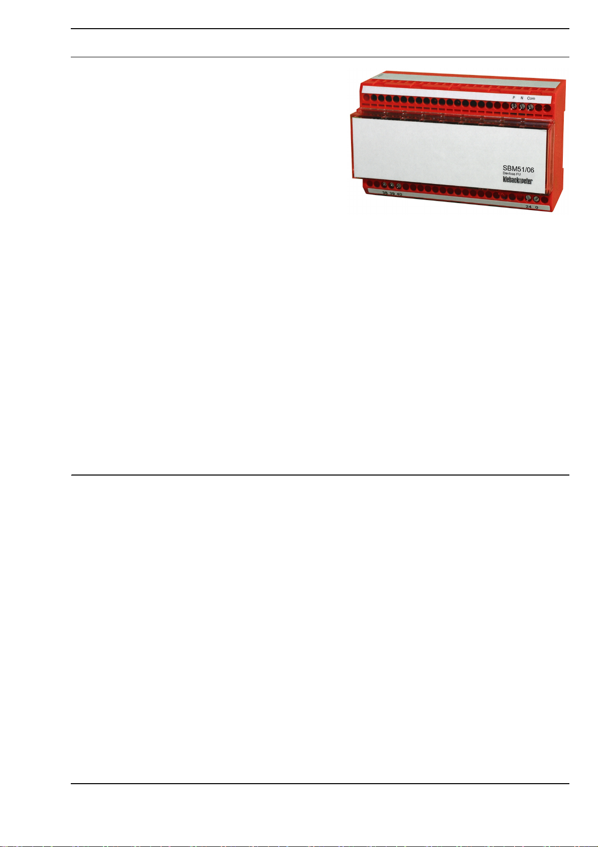
SBM51/06 Gateway Module for Danfoss Frequency
Inverters
Application
The SBM51/06 gateway module can be used to connect up
to eight different types of Danfoss frequency inverter (FI), via
the Danfoss bus, to the DDC3000/DDC4000 automation
system. The connection is made via the RS485 interface of
the SBM51/06. Danfoss FC protocol is used for communication.
You can use the following Danfoss series:
VLT 2800 series, VLT 5000 series, VLT 6000 series, VLT
HVAC Drive FC 102, VLT AQUA Drive FC 202, VLT AutomationDrive FC 301, VLT AutomationDrive FC 302, VLT Micro
Drive FC 51
SBM51/06
Content Page
Important Information Regarding Product Safety ..................................................................................................2
Item........................................................................................................................................................................3
Technical Data.....................................................................................................................................................3
Dimensions..........................................................................................................................................................3
Connection...........................................................................................................................................................4
Installation and Removal .......................................................................................................................................6
Commissioning ......................................................................................................................................................7
Switching on the Power .........................................................................................................................................9
SBM51/06 Parameter Description .......................................................................................................................10
Basic Program ...................................................................................................................................................10
Parameter Lists for the DDC Software Menus M090 and CD_SB51 (SBM51 Gateway) ..................................12
Project Planning: Frequency Inverter - SBM51/06 ..............................................................................................20
Determining Speed (Using the VLT 6000 as an Example) ................................................................................20
Malfunction messages .......................................................................................................................................20
V-Belt Monitoring (Load shedding) ....................................................................................................................20
Comparison Tables for the Software Menu M090 and CD_SB51: Parameter - Data Points...............................22
Änderungen vorbehalten - Contents subject to change - Sous réserve de modifications - Reservado el derecho a modificación - Wijzigingen
voorbehouden - Con riserva di modifiche - Innehåll som skall ändras - Změny vyhrazeny - Zmiany zastrzeżone - Возможны изменения
A változtatások jogát fenntartjuk -
Kieback&Peter GmbH & Co. KG
Tempelhofer Weg 50, 12347 Berlin/Germany
Telefon: +49 30 60095-0, Telefax: +49 30 60095-164
www.kieback-peter.de, info@kieback-peter.com
保留未经通知而改动的权力
A
-
Page 2
Datasheet 2.50-40.051-71-EN
!
Important Information Regarding Product Safety
Safety Instructions
This data sheet contains information on installing and commissioning the product "SBM51/06". Each
person who carries out work on this product must have read and understood this data sheet. If you
have any questions that are not resolved by this data sheet, you can obtain further information from
the supplier or manufacturer.
If the product is not used in accordance with this data sheet, the protection provided will be impaired.
Applicable regulations must be observed when installing and using the device. Within the EU, these
include regulations regarding occupational safety and accident prevention as well as those from the
VDE (Association for Electrical, Electronic & Information Technologies). If the device is used in other
countries, it is the responsibility of the system installer or operator to comply with local regulations.
Mounting, installation and commissioning work on the devices may only be carried out by qualified
technicians. Qualified technicians are persons who are familiar with the described product and who
can assess given tasks and recognize possible dangers due to technical training, knowledge and
experience as well as knowledge of the appropriate regulations.
Legend
WARNING
Indicates a hazard of medium risk which can result in death or severe bodily injury if it is not avoided.
Product DescriptionSBM51/06
CAUTION
Indicates a hazard of low risk which can result in minor or medium bodily injury if it is not avoided.
NOTICE
Indicates a hazard of medium risk which can result in material damage or malfunctions if it is not
avoided.
NOTE
Indicates additional information that can simplify the work with the product for you.
Notes on Disposal
For disposal, the product is considered waste from electrical and electronic equipment (electronic
waste) and must not be disposed of as household waste. Special treatment for specific components
may be legally binding or ecologically sensible. The local and currently applicable legislation must be
observed.
A
Page 2 / 26
Page 3
Item
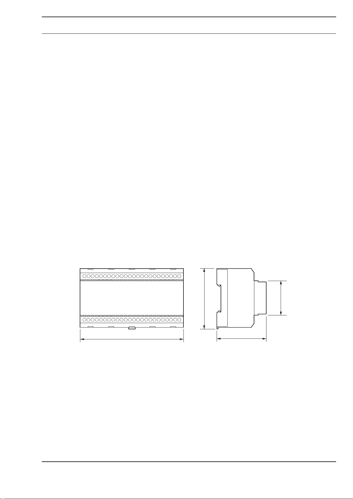
44,7
77,0
60,0
125,0
SBM51/06 Gateway Module for Danfoss Frequency Inverters
Technical Data
Nominal voltage For device: AC 24 V ±10% / 230 mA, max. 5.4 VA
Fuse Electronic fuse protection for AC 24 V power
Indicators and Controls ■ 2 LEDs in housing
Interfaces ■ Switch cabinet bus to DDC system
Degree of protection IP20
Ambient temperature 0 C to 45 °C
Ambient humidity 20 to 80 % r.h., non-condensing
Installation Switch cabinet installed on top hat rail DIN EN 50022 – 35 x 7.5
Dimensions
(WxHxD in mm)
Datasheet 2.50-40.051-71-EN
SBM51/06Product Description
■ 2 rotary switches in housing, for setting the switch cabinet bus address
■ Serial interface/RS485 bus (FC protocol)
125 x 77 x 60
Compatibility
Dimensions
SBM51/06 is supported as follows:
■ DDC3000 as of version 6.7
■ DDC4000 as of version 1.2.430
■ Photon BMS as of version 6.41
Page 3 / 26
A
Page 4
Datasheet 2.50-40.051-71-EN
!
!
System
DDC3000
DDC4000
38 39 40
38 39 40 38 39 40
System
DDC4000
18 19 20
24V~
0V~
24 0
PN
COM
SBM51/06
Danfoss RS485
68
69
Danfoss RS485
RS485
68
69
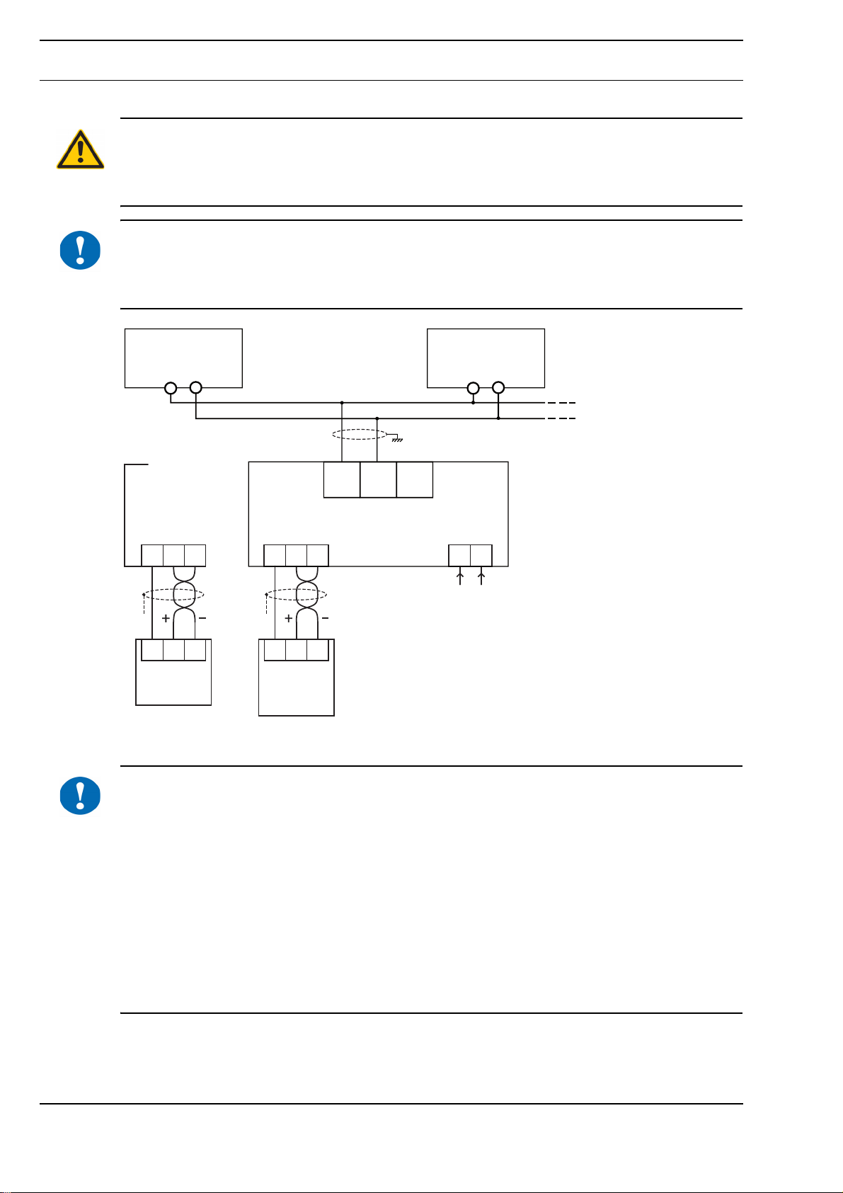
Connection
WARNING
Contact with live parts of electrical domestic installation can cause death due to electric shock.
Only connect the device and switch on the power supply if you are qualified to do so. Be sure to
comply with VDE guidelines and local wiring regulations.
NOTICE
Switching on the power supply of unparameterized products can lead to unforeseen consequences
such as malfunctions or material damage.
Switch on the power only after the device has been configured by the commissioning technician.
Product DescriptionSBM51/06
NOTICE
A
Position the SBM51/06 such that it is connected between two Danfoss frequency inverters on the bus
(internal nodes in the network). Terminate the Danfoss bus using an internal DIP switch in the first
and last frequency inverter. This means you are able to achieve the best immunity to disturbance for
the bus system.
During commissioning, ensure that the Danfoss bus system is connected correctly. The Danfoss bus
must not be connected the wrong way round.
If it is not possible to position the SBM51/06 between two frequency inverters (external nodes in the
network), terminate the bus using an 180 Ohm terminating resistor between the terminals P and N.
Activate the terminating resistor of the FI at the other end of the line.
The shield is positioned on the spring-type terminal (or clamp for older VLT models) on one side of
the FI only. The COM terminal on the SBM51/06 is not used and is only used in environments with
severe interference. Clarify connection with Danfoss Support.
Page 4 / 26
Page 5
Datasheet 2.50-40.051-71-EN
SBM51/06Product Description
NOTE
The bus-systems switch cabinet bus (DDC3000) and CAN bus (DDC4000) are identical. Hence, all
technical information relating to the switch cabinet bus also apply to the CAN bus.
Switch cabinet bus
When connecting the switch cabinet bus, use a cable of at least type JY(St)Y 2x2x0.8 Lg: two x two
leads stranded into a pair, plastic insulation and an electrostatic shield with a lead diameter of at least
0.8 mm. Use a stranded pair of leads for the data lines (+ and -) and another free lead for the ground
(0).
At the end of the switch cabinet bus (furthest point from the controller), install a terminating resistor
of about 180 ohms between the two data lines (+ and -). The terminating resistor is included with the
controller.
The maximum cable length for the switch cabinet bus is 200 m.
NOTE
For a connection to a DDC4000, the data rate of the CAN bus used must be 40 kBd. Use the
"SY_CAN.xx" system variable to make the setting.
Page 5 / 26
A
Page 6
Datasheet 2.50-40.051-71-EN
!
EN 50022
1
1
5
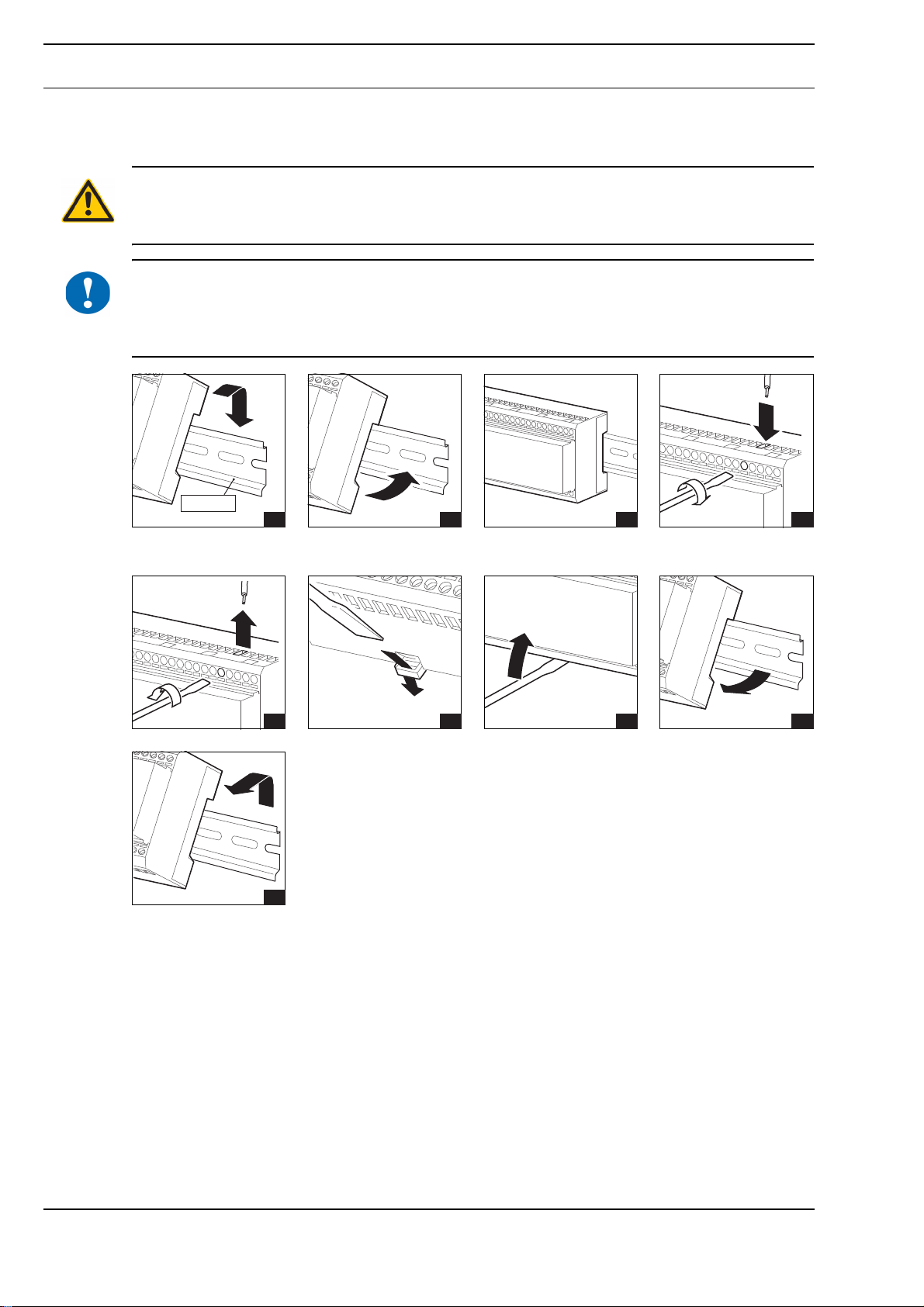
Installation and Removal
Installation
WARNING
Contact with live parts of electrical domestic installation can cause death due to electric shock.
Mounting/removal may only be carried out when power is switched off.
NOTICE
Switching on the power supply of unparameterized products can lead to unforeseen consequences
such as malfunctions or material damage.
Switch on the power only after the device has been configured by the commissioning technician.
Product DescriptionSBM51/06
Removal
2 3 4
2 3 4
A
Page 6 / 26
Page 7
Commissioning
!
12
NOTICE
Power may only be switched on after the DDC controller and device have been configured by the
commissioning technician.
Configuration of the DDC controller is described in the respective project planning documentation.
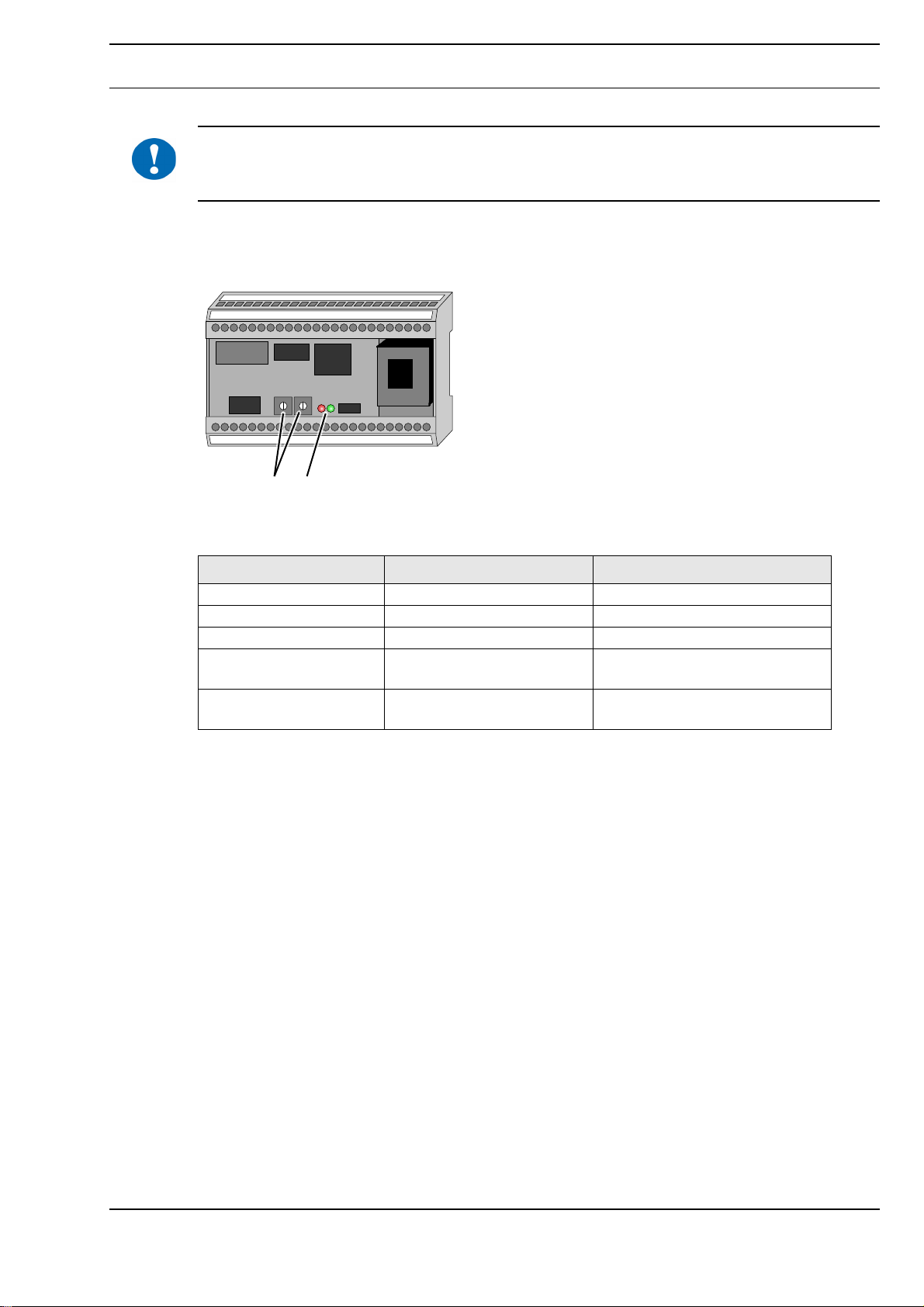
Indicators and Controls
Datasheet 2.50-40.051-71-EN
SBM51/06Product Description
1 Rotary switch for setting the switch cabinet bus address
2 Switch cabinet bus LED
LED Signal Meaning
Switch cabinet bus LED Green SBM51/06 is operating
Switch cabinet bus LED Flashing green Data transmission
Switch cabinet bus LED Red SBM51/06 not registered
Switch cabinet bus LED Flashing red, on/off time at a
ratio of 50:50
Switch cabinet bus LED Flashing red, on/off time at a
ratio of 25:75
Doubled address
Invalid address
Page 7 / 26
A
Page 8
Datasheet 2.50-40.051-71-EN
0
1
2
3
4
5
6
7
8
9
0
1
2
3
4
5
6
x 10 x 1
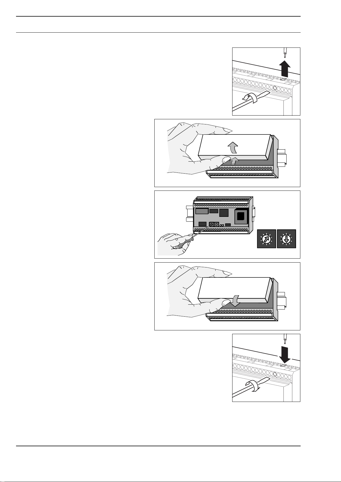
Setting the switch cabinet bus address
► Disconnect the power supply of the SBM51/06.
► Press the lower edge of the front
cover and remove the cover.
The rotary switches for setting the switch
cabinet bus address are located inside
the SBM51/06.
Product DescriptionSBM51/06
► Set the first rotary switch to the first
digit of the switch cabinet bus
address, and the second rotary
switch to the second digit.
The example shows the address “15”.
Permitted range for the switch cabinet
bus address: 01 to 16
► Insert the front damper along the top
edge and lock it in with the bottom
edge.
► Reconnect the power supply of the SBM51/06.
A
Page 8 / 26
Page 9

Switching on the Power
WARNING
Contact with live parts of electrical domestic installation can cause death due to electric shock.
Only connect the device and switch on the power supply if you are qualified to do so. Be sure to
comply with VDE guidelines and local wiring regulations.
Before switching on the power, ensure that the device has been mounted correctly and check the
electrical connection.
After turning on the power, check the transmission function of the SBM51/06.
Datasheet 2.50-40.051-71-EN
SBM51/06Product Description
Page 9 / 26
A
Page 10

Datasheet 2.50-40.051-71-EN
!
SBM51/06 Parameter Description
Content of the parameter description
The parameter description contains information regarding SBM51/06 DDC3000/DDC4000 system
parameterization.
Firmware version
This parameter description describes SBM51/06 firmware as of version 6.0.
NOTE
When using frequency inverters, it may, depending on the series and the application, be necessary
to take interference suppression measures. In this case, please contact Danfoss.
NOTICE
Per DDC3000/DDC4000 system, a maximum of five SBM51, regardless of type, may be connected
to the switch cabinet bus.
Product DescriptionSBM51/06
Basic Program
Registering the SBM51/06 on the DDC
After switching the supply voltage on, the SBM51/06 checks the availability of the switch cabinet bus
and uses the basic program to register with the DDC3000/DDC4000 automation system. In addition,
the SBM51/06 automatically registers the connected frequency inverter with the DDC.
Parameter List in the DDC3000 System
The SBM51/06 basic program contains the following parameters:
Parameter
No.
899 Central unit/KK version Text (invalid)
2202 Q bus mode 0; 1 (0)
2203 Q cycle 0; 1 (0)
2204 Foreign bus OK 0; 1 (invalid)
These parameters apply for all Danfoss frequency inverters connected to the SBM51/06.
Parameter 899 “Central unit/KK version”
In parameter 899 Central unit/KK version, the SBM51/06 registers its firmware version.
Parameter 2202 “Q Bus Mode”
Parameter 2202 Q bus mode turns the communication for the bus system (FC bus) on or off:
■ “0” → FC bus OFF
■ “1” → FC bus ON.
Parameter plain text Value range
(Initial value)
Parameter 2203 “Q Cycle”
The parameter 2203 Q cycle is not needed for SBM51/06.
Parameter 2204 “Foreign Bus OK”
In parameter 2204 foreign bus OK, the SBM51/06 registers malfunctions on the FC bus:
■ “1” → The FC bus is working without errors.
■ “0” → Errors occurred on the FC bus.
A
Page 10 / 26
Page 11

Datasheet 2.50-40.051-71-EN
SBM51/06Product Description
DDC Software Menu M090 (SBM51 gateway)
The DDC software menu, M090 SBM51 gateway (previously gateway menu), can be set to the
SBM51/06 basic program up to 32 times. Two gateway menus with addresses 1 and 2, 3 and 4, etc.
and the menu with address 32 are automatically created per FI. A maximum of 17 M090 menus are
therefore required for a maximum of eight FIs that can be connected.
The parameter lists for the DDC software menu M090 are described in section “Parameter Lists for
the DDC Software Menus M090 and CD_SB51 (SBM51 Gateway)” from page 12.
Parameter List in the DDC4000 System
SY_SBM51 “System SBM51” System Object
The SY_SBM51 “System SBM51” system object contains parameters that represent the special
characteristics of an SBM51/06 as a gateway module:
Parameter Plain text Setpoint /
value
Cycle Readout cycle Setpoint Binary
Enable Bus enable Setpoint Binary
Cycle Parameter: "Readout cycle"
The parameter cycle readout cycle is not needed for SBM51/06.
Enable parameter: “Enable bus”
The Enable parameter turns the communication for the bus system (FC bus) on or off:
■ “0” → FC bus OFF
■ “1” → FC bus ON.
Hardware Object H000 “Device on Bus”
When creating an SBM51/06 in the DDC4000 central unit, 32 H000 hardware objects “Device on bus”
are automatically created under /b1/00. Of those, only the following 17 hardware objects are used:
01 to 16 and 32.
Each H000 hardware object contains the Active and Config parameters that represent the special
characteristics of a frequency inverter on the bus.
Parameter Plain text Setpoint /
value
Active Pin active Value Binary value
Config Configuration Setpoint Binary value
Type
value
value
Type
Page 11 / 26
Active Parameter
The parameter Active shows if the FI was registered on the bus.
■ “1” → FI is registered on the bus.
■ “0” → FI is not registered on the bus.
Parameter Config
Create the gateway menu CD_SB51 “SBM51 Menu” via Parameter Config.
A
Page 12

Datasheet 2.50-40.051-71-EN
Parameter Lists for the DDC Software Menus M090 and CD_SB51 (SBM51 Gateway)
M090 (for DDC3000) and CD_SB51 (for DDC4000)
According to the following principle, two DDC software menus M090 or CD_SB51 are assigned to
every Danfoss frequency inverter:
■ the menus /01 and /02 for the frequency inverter with address 1
■ the menus /03 and /04 for the frequency inverter with address 2, etc.
When using a DDC3000, the basic program of the SBM51/06 is expanded with additional DDC
software menus M090 according to the number of frequency inverters to be added. When using a
DDC4000, all 32 menus are automatically created.
Software Menu M090 and CD_SB51: Resync/Diag /31 Menu
The Resync/Diag menu is activated with parameter 2216. The SBM51/06 recognizes the menu used
by the DDC based on the menu number of parameter 2216.
The module manages the parameters as standard analog actual values in software menu /31 and
sends this as Q analog actual value 1 - Q analog actual value 8 to the automation station.
Parameter Plain text Meaning
2209 External system ok (only DDC3000) Participant is registered
2210 Analog actual value 1 Can_Resync_Counter
2211 Analog actual value 2 DDC timeout
2212 Analog actual value 3 Prompt to register again
2251 Analog actual value 4 BUSOFF
2215 Analog actual value 5 CAN hardware error
2252 Analog actual value 6 CAN message error
2253 Analog actual value 7 New address
2254 Analog actual value 8 Doubled address
2240 Q analog setpoint 1 Can_Resync_Time
2216 Q digital setpoint 1 ActivateMenu
2220 Q digital setpoint 2 Can_Resync_ Counter Reset
2245 Q digital setpoint 3 ActivateResync
Product DescriptionSBM51/06
NOTE
The Resync/Diag menu is not explicitly registered with the automation station by the SBM51/06.
Parameter 2209 “External System OK”
Only applies for DDC3000.
Parameter 2251 “Analog Actual Value 4” and 2215 "Analog Actual Value 5"
Contains a CAN controller message.
All Parameters “Analog Actual Value x”
Upon exceeding the upper limit, the “Analog actual value x” parameters are set to zero.
Parameter 2252 “Analog Actual Value 6”
Contains CAN messages addressed to the SBM, but which have not yet been processed.
Parameter 2240 “Q Analog Setpoint 1”
Parameter 2240 specifies the time period in seconds after a CAN bus error, within which data integrity
and communication with the automation station is to be restored using the Resync process.
A
Page 12 / 26
Page 13

Datasheet 2.50-40.051-71-EN
SBM51/06Product Description
A module reset is performed if the Resync process could not be completed for all registered
frequency inverters.
Parameter 2216 “Q Digital Setpoint 1”
Parameter 2216 switches bus system (FC bus) communication on or off:
■ “0” or “invalid” → Diagnosis function is inactive
■ “1” → Diagnosis function is active
Parameter 2245 “Q Digital Setpoint 3”
You can activate or deactivate the Resync function with parameter 2245.
■ “0” or “invalid” → Resync function is inactive
■ “1” → Resync function is active
Page 13 / 26
A
Page 14

Datasheet 2.50-40.051-71-EN
First DDC Software Menu M090 and CD_SB51 (Odd-Numbered Addresses)
Menus /01, /03, /05, /07, /09, /11, /13, /15 --- Danfoss frequency inverter VLT 5000, VLT 6000,
VLT 2800, FC 102, FC 202, FC 301, FC 302, FC 51
Parameter Plain text Meaning Unit
2209 External system ok (only DDC3000) Participant is registered 2210 Analog actual value 1 FI type 2211 Analog actual value 2 Voltage type 2212 Analog actual value 3 Service life h
2251 Analog actual value 4 Operating time h
2215 Analog actual value 5 Rated motor speed rpm
2252 Analog actual value 6 Absolute speed rpm
2253 Analog actual value 7 User-defined display 2254 Analog actual value 8 Relative rotary frequency %
2255 Analog actual value 9 Absolute rotary frequency Hz
2256 Analog actual value 10 Motor current IRMS A
2257 Analog actual value 11 Performance kW
2258 Analog actual value 12 Energy consumption kWh
2240 Q analog setpoint 1 Relative setpoint rotary frequency %
2241 Q analog setpoint 2 Minimum setpoint PS1 Hz
2242 Q analog setpoint 3 Maximum setpoint PS1 Hz
2222 Digital actual value 1 Error/malfunction 2224 Digital actual value 2 General warning 2225 Digital actual value 3 Ready for operation 2226 Digital actual value 4 switched on 2227 Digital actual value 5 Setpoint reached 2228 Digital actual value 6 Warning
2216 Q digital setpoint 1 Motor enable 2220 Q digital setpoint 2 Freewheel stop 2245 Q digital setpoint 3 Malfunction acknowledgment 2246 Q digital setpoint 4 Parameter set selection 2217 Operating mode Stop, automatic, manual
Product DescriptionSBM51/06
-
Load shedding
1 = Stop
7 = Auto
8 = Manual
NOTE
The Danfoss frequency inverters that can be connected to the SBM51/06 do not support all possible
parameters (see parameter reference tables from page 22).
Parameter 2209 “External System OK”
Is set to “0” when the communication to the external system is interrupted.
Parameter 2251 “Analog Actual Value 4”
Counts the operating hours of the connected motor.
A
Page 14 / 26
Page 15

Datasheet 2.50-40.051-71-EN
SBM51/06Product Description
Parameter 2215 “Analog Actual Value 5”
Parameter 2215 is only read once when the FI is registered. If the parameter is changed during
operation, the new value is only valid when the FI has been registered again.
Parameter 2253 “Analog Actual Value 7”, 2254 “Analog Actual Value 8” and 2240 “Q Analog
Setpoint 1”
Further parameterization information can be found in the following project planning sections.
Parameter 2222 “Digital Actual Value 1”
The FI switches off in the event of a malfunction. The malfunction must be acknowledged via digital
setpoint 3 (2245) = 1. Remedy the cause of the error before acknowledgment.
Parameter 2224 “Digital Actual Value 2”
Warning messages are automatically canceled when the operating conditions are back within the
normal range.
Parameter 2217 Operating mode
Auto = Motor running
Stop = Motor not running
Manual = FI is in manual mode
Parameter 2241 “Q Analog Setpoint 2” and 2242 “Q Analog Setpoint 3”
Contain the setpoint limits for parameter set 1.
Page 15 / 26
A
Page 16

Datasheet 2.50-40.051-71-EN
Second DDC Software Menu M090 and CD_SB51 (Even-Numbered Addresses)
Menus /02, /04, /06, /08, /10, /12, /14, /16 --- Danfoss frequency inverter VLT 5000, VLT 6000,
VLT 2800, FC 102, FC 202, FC 301, FC 302, FC 51
Parameter Plain text Meaning Unit
2209 External system ok (only DDC3000) Participant is registered 2211 Analog actual value 2 Active parameter set 2251 Analog actual value 4 Setpoint error 2215 Analog actual value 5 Actual value error 2252 Analog actual value 6 Rel. error 2253 Analog actual value 7 Analog input terminal 54 V
2254 Analog actual value 8 Motor voltage V
2255 Analog actual value 9 Minimum setpoint Hz
2256 Analog actual value 10 Maximum setpoint Hz
2240 Q analog setpoint 1 Parameter set selection, actual
2241 Q analog setpoint 2 Minimum setpoint PS2 2242 Q analog setpoint 3 Maximum setpoint PS2 2222 Digital actual value 1 Mains phase error 2224 Digital actual value 2 Thermal warning 2225 Digital actual value 3 Voltage high/low 2226 Digital actual value 4 Not in freq. range 2227 Digital actual value 5 Dig. input terminal 32 2228 Digital actual value 6 Dig. input terminal 33 2216 Q digital setpoint 1 Relay 1 on 2220 Q digital setpoint 2 Relay 2 on 2245 Q digital setpoint 3 Activate relay 2246 Q digital setpoint 4 DC brake 2217 Operating mode Stop, automatic, manual
Product DescriptionSBM51/06
-
value mode
1 = Stop
7 = Auto
8 = Manual
NOTE
The Danfoss frequency inverters that can be connected to the SBM51/06 do not support all possible
parameters (see parameter reference tables from page 22).
Parameter 2241 “Q Analog Setpoint 2” and 2242 “Q Analog Setpoint 3”
Contain the setpoint limits for parameter set 2.
Parameter 2240 “Q Analog Setpoint 1”
Special features for registering/deregistering FIs in the event of invalid parameter 2240 configuration
in the second DDC software menu:
■ If “1” - “4” (no external selection) is configured as a parameter set in the FI, the SBM is in actual
value mode and parameter 2240/02 is not relevant.
When the FI is registered again:
■ If an external selection is configured as a parameter set in the FI and the parameter 2240/02 has
the values “0”, > “4” or “invalid”, the SBM switches to actual value mode and returns the value “0”
for parameter 2211/02.
A
Page 16 / 26
Page 17

Datasheet 2.50-40.051-71-EN
SBM51/06Product Description
During operation:
■ If an external selection is configured as a parameter set in the FI and parameter 2240/02 is “0”, is
larger than “4”, or becomes invalid, parameter 2211/02 then stays at the last valid value.
■ If an external selection is configured as a parameter set in the FI and the parameter 2240/02 has
the values “1” - “2”, the SBM sets the selected parameter set and sends the setpoints.
NOTE
The SBM51/06 can switch to four parameter sets. Only the first two parameter sets can be parameterized in the SBM51/06. The settings are active in the FI for parameter sets 3 and 4.
Parameters 2215, 2251 and 2252
The parameters 2251, 2215 and 2252 have special functions which you enable in menu 32:
■ Parameter 2251 - Parameterization communication error, setpoints
■ Parameter 2215 - Communication error, actual values
■ Parameter 2252 - Communication error, relay control
Software Menu M090 and CD_SB51 Menu 32
In software menu “Menu 32” (Address = 32), it is possible to set special parameters, e.g. maximum
number of FIs on the bus and the display of error values.
Parameter Plain text Meaning
2209 External system ok (only DDC3000) Participant is registered
2210 Analog actual value 1 Number of FIs on the bus
2240 Q analog setpoint 1 Max. number of FIs
2241 Q analog setpoint 2 Parameter retention
2242 Q analog setpoint 3 Display error values
Parameter 2210 “Analog Actual Value 1”
Number of FIs found on the bus
Parameter 2240 “Q Analog Setpoint 1”
Selection of the maximum number of FIs that can be operated on the bus
Specifying a smaller number of FIs (e.g. three) reduces the cycle time, as only FIs with addresses 1,
2 and 3 are known on the bus. FIs with higher addresses are not taken into account and their parameters are not updated.
Parameter 2241 “Q Analog Setpoint 2”
Only applies for DDC3000:
■ “0” → The existing parameters will be deleted.
■ “1” → Following an interruption in bus communication, the frequency inverters will be configured
with retained parameters when registering again (parameter setpoint min/ max 1/2, current
setpoint, enable, freewheel stop, malfunction acknowledgment).
Page 17 / 26
Parameter 2242 “Q Analog Setpoint 3”
The internal error counter display in the second FI menu
■ “0” → Display inactive
■ “1” → Display active
The counters are deleted when the SBM51/06 is restarted.
A
Page 18

Datasheet 2.50-40.051-71-EN
!
Function description
Function of the Analog Setpoint and Parameter Set Switching
The central unit specifies a frequency setpoint for each frequency inverter via the parameter 2240 “Q
analog setpoint 1” of the first respective menu, SBM51 gateway.
Using the following parameters of the first respective menus M090 and CD_SB51, you can scale the
specified parameters for the first parameter set of the frequency inverter:
■ 2241 “Q analog setpoint 2” for the minimum frequency setpoint (parameter 204)
■ 2242 “Q analog setpoint 3” for the maximum frequency setpoint (parameter 205)
You can specify the scaling for the second parameter set of the frequency inverter using the same
parameters of the second respective menu, SBM51 gateway.
If no parameters are set, the local frequency inverter settings apply.
Entering negative frequency setpoint values leads to incorrect setpoint calculation.
NOTICE
The values of parameters 2241 “Q analog setpoint 2” and 2242 “Q analog setpoint 3” are only
sent to the FI when parameter 2241 is smaller than parameter 2242. Otherwise, FI malfunctions can
result which can only be reset by switching off the FI. The maximum FI setpoint can, due to the abovementioned condition, not be set to zero by parameter 2242. Value “0” can; however, be set manually
on the FI.
Always set the parameter for the maximum frequency setpoint before setting the parameter for the
minimum frequency setpoint.
The parameters for the minimum and maximum frequency setpoint values cannot be changed during
operation. Changes made are only active following motor stop.
Product DescriptionSBM51/06
Switch the parameter set using parameter 2240 “Q analog setpoint 1” of the second respective
menu, SBM51 gateway (see Parameter 2240 “Q Analog Setpoint 1”, page 16).
The “remote” setpoint is only adopted by the SBM51/06 in automatic FI mode. When the FI is in
manual mode, the frequency inverter uses the “on-site setpoint”.
If necessary, the actual value is sent as the setpoint if no parameters are set (display “deleted”) in
parameter 2240 "Q analog setpoint 1". If a setpoint was set on-site on the frequency inverter, the
motor will continue to operate with the setpoints set on-site.
No setpoints are sent to the FI for actual value mode (parameter 2240 of the second respective menu)
. The FI runs with the on-site setpoints.
Function Following Interruption of the Danfoss Bus to the SBM51/06 (Using the VLT 6000 as
an Example)
Using the frequency inverter parameters “555 bus time interval” and “556 bus time interval”, you can
define which operating state the frequency inverter should adopt following bus interruption. “OFF” is
set as standard. The frequency inverter starts automatically as soon as the bus is ready for operation
again.
Refer to the Danfoss project planning documentation for information on settings for other types of FI.
SBM Behavior in the Event of an Error on the Switch Cabinet Bus (Diagnosis Function)
Resync functions are not yet supported by DDC3000 and DDC4000. Parameter 2240 “Q analog
setpoint 1” (Can_Resync_Time) in Resync/Diag menu is used for the diagnosis function (see page
12).
■ When the Resync process is inactive on the DDC, the parameter 2240/31 [00] acts as a timeout
for SBM re-registration. FI operation is then interrupted.
■ Parameter 2245 “Q digital setpoint 3” does not have any effect.
A
Page 18 / 26
Page 19

Datasheet 2.50-40.051-71-EN
!
SBM51/06Product Description
Digital Parameter Function
First Menu SBM51 Gateway (Odd-Numbered Addresses)
Set the FI motor enable via the parameter 2216 “Q digital setpoint 1”.
NOTICE
If the parameter 2216 “Q digital setpoint 1” has not been configured, it is not possible to enable the
motor in automatic FI mode. The motor remains at a standstill.
NOTE
When the value of parameter 2216 “Motor enable” changes, parameter 2254 can adopt a negative
value.
Motor freewheel stop is activated using parameter 2220 “Q digital setpoint 2”.
If the value of parameter 2220 is 1, the motor will coast down to a stop. This function has higher
priority than motor enable (parameter 2216). This function has no effect if parameter 2220 has not
been configured. This function is used in conjunction with the motor flying start function (see the
commissioning instructions from Danfoss).
Acknowledging Alarms
Set FI alarm acknowledgment via the parameter 2245 “Q digital setpoint 3”. Messages are always
acknowledged via the 0/1 edge of the assigned digital signal.
Second Menu SBM51 Gateway (Even-Numbered Addresses)
You can control the first two relay outputs with the SBM51/06 if the Danfoss frequency inverter is
equipped with relay outputs. Relay control is enabled via the parameter 2245 “Q digital setpoint 3”.
If the value of parameter 2245 is 1, the frequency inverter relay outputs can be controlled via the DDC
system.
Relay 1 is controlled via the 2216 “Q digital setpoint 1” parameter, relay 2 is controlled via the
parameter 2220 “Q digital setpoint 2”.
The values of the parameters 2216 and 2220 result in the following relay contact state:
■ “0” or “deleted” → Relay is switched
■ “1” → Relay is not switched
The DC brake of the frequency inverter is activated using parameter 2246 “Q digital setpoint 4”.
The value of parameter 2246 has the following effect on the state of the DC brake:
■ “0” or “deleted” → The DC brake is switched off.
■ “1” → The DC brake is active.
Page 19 / 26
A
Page 20

Datasheet 2.50-40.051-71-EN
Project Planning: Frequency Inverter - SBM51/06
Commissioning (Using the VLT 6000 as an Example)
You can connect one to eight different types of Danfoss frequency inverter to theSBM51/06.
For commissioning, make the following settings on the frequency inverter:
■ “FI Parameter 500, protocol: FC protocol (default setting)
■ “FI parameter 501, bus address: set an address between 1 and 8
■ “FI parameter 502, baud rate: 9600 Bd (default setting)
■ “FI parameter 106, rated motor speed: is important when the speed is to be displayed on the
parameter “User-defined display 2253/01”.
■ “FI parameter 006, unit of the “Free display”: 0, when the SBM51/06 is to perform configuration
for determining speed.
Refer to the commissioning instructions from Danfoss for further information.
Determining Speed (Using the VLT 6000 as an Example)
Parameter 2253/01 can be used to determine the speed if parameter 2252/01 “Absolute Speed” is
not supported by the FI type at hand. To do this, enter the nominal motor speed for FI parameter 005
(maximum value for user-defined display) on the frequency inverter. This value must completely
match the output frequency value.
FI parameter 2253/01 then outputs the speed.
If the SBM51/06 is to apply the speed via parameter 2253 “Analog actual value 7”, FI parameter
006 (unit of the scaled display) must be left at 0 (= default setting).
The unit from FI parameter 006 (nominal motor speed) is automatically set to rpm.
If the free display is to be used in another way, FI parameter 006 (unit of the scalable value) must be
set such that it is not equal to “0”. In this case, automatic configuration of the SBM51/06 remains
undone. The value displayed in the first respective software menu, SBM51 gateway, parameter 2253
“Analog actual value 7” is then a different value.
Product DescriptionSBM51/06
Malfunction messages
The parameter 2222 “Malfunction” of the first respective software menu, SBM51 gateway, is
generated in the frequency inverter using all bits from the frequency inverter alarm word.
Every alarm in the frequency inverter triggers the following actions:
■ Sets the malfunction message contact and sets parameter 2222 “Malfunction” to “1”
■ Switches the frequency inverter off
Acknowledge the alarm by pressing the reset button on the frequency inverter. Alternatively, there is
a way to acknowledge alarms via the DDC system (see page 19).
Warnings do not lead to a collective malfunction message.
Thermal Monitoring
Parameter 2224 “Digital actual value 2” of the second respective software menu, SBM51 gateway,
indicates motor thermal overload.
Thermal overload on the motor is determined either via monitoring of the electrical values of the motor
in the frequency inverter or by a thermistor installed in the motor. The motor protection type is set on
the FI (e.g. using parameter 117 for the VLT6000).
Thermal monitoring messages for the FI are reported in the collective malfunction message
parameter 2222 “Malfunction” of the first respective software menu, SBM51 gateway.
V-Belt Monitoring (Load shedding)
On the frequency inverter (e.g. using parameter 221 for the VLT6000), set the Lower current limit
that corresponds to load shedding due to a V-belt tear. Doing this makes it possible for parameter
2228 “Digital actual value 6” of the second respective software menu, SBM51 gateway, to display the
“V-belt malfunction” message correctly.
A
Page 20 / 26
Page 21

Danfoss recommends you set the lower current limit (idle current without V-belt) to a maximum
frequency of + 5 %.
The behavior of the FI in the event of minimum current can be set on the FI.
Additional Alarms and Warnings
Refer to the parameter table in this document for additional alarms and warnings.
Special functions
The number of frequency inverters can be set in order to ensure an optimal readout time (see
Software Menu M090 and CD_SB51 Menu 32, page 17). If, for instance, only three frequency
inverters are set, the SBM51/06 will only search addresses 1 to 3. This results in a shorter cycle time.
Datasheet 2.50-40.051-71-EN
SBM51/06Product Description
Page 21 / 26
A
Page 22

Datasheet 2.50-40.051-71-EN
Product DescriptionSBM51/06
Comparison Tables for the Software Menu M090 and CD_SB51: Parameter - Data Points
Parameter Reference Table
Software Menu M090 and CD_SB51: /01, /03, /05, /07, /09, /11, /13, /15 --- Danfoss Frequency
Inverters VLT 6000, VLT 5000, VLT 2800
Para
meter
2210 Analog actual value 1 FI type 621 621 621
2211 Analog actual value 2 Voltage type 621 621 621
2212 Analog actual value 3 Service life 600 600 600
2251 Analog actual value 4 Operating time 601 601 601
2215 Analog actual value 5 Rated motor
2252 Analog actual value 6 Speed calculated - - 2253 Analog actual value 7 User-defined
2254 Analog actual value 8 Relative rotary
2255 Analog actual value 9 Absolute rotary
2256 Analog actual value 10 Motor current
2257 Analog actual value 11 Performance 515 522 522
2258 Analog actual value 12 Energy
2240 Q analog setpoint 1 Relative rotary
2241 Q analog setpoint 2 Minimum
2242 Q analog setpoint 3 Maximum
2222 Digital actual value 1 Error/malfunction State word. 03/04State word. 03 State word. 03/
2224 Digital actual value 2 General warning State word. 07 State word. 07 State word. 07
2225 Digital actual value 3 Ready for opera-
2226 Digital actual value 4 switched on State word. 11 State word. 11 State word. 11
2227 Digital actual value 5 Setpoint reached State word. 08 State word. 08 State word. 08
2228 Digital actual value 6 Warning
2216 Q digital setpoint 1 Motor enable Control word. 06Control word. 06Control word.
2220 Q digital setpoint 2 Freewheel stop Control word. 03Control word. 03Control word.
2245 Q digital setpoint 3 Malfunction
2217 Operating mode Stop, manual,
DDC Parameter Text Meaning VLT 6000 Data
Points
106 106 106
speed
513 558 -
display
State word/
frequency
frequency
IRMS
consumption
frequency
setpoint
setpoint PS1
setpoint PS1
tion
Load shedding
acknowledgment
automatic
output
frequency
512 518 518
514 520 520
602 602 602
Control word/
setpoint
frequency
204 204 204
205 204 205
State word. 01 State word. 01 State word. 01
---
Control word. 07Control word. 07Control word.
State word. 11/09State word. 11/09State word. 11/
VLT 5000 Data
Points
State word/
output
frequency
Control word/
setpoint
frequency
VLT 2800 Data
Points
State word/
output
frequency
Control word/
setpoint
frequency
04
06
03
07
09
A
Page 22 / 26
Page 23

Datasheet 2.50-40.051-71-EN
SBM51/06Product Description
Parameter 2253 on the Frequency Inverter VLT 5000
The “User-defined display” parameter is not available on the FI VLT 5000. Data point 558 (“Motor rpm
x scaling”) is output to parameter 2253/01 “User-defined display”.
Parameter Reference Table
Software Menu M090 and CD_SB51: /02, /04, /06, /08, /10, /12, /14, /16 --- Danfoss Frequency
Inverters VLT 6000, VLT 5000, VLT 2800
Para
meter
2211 Analog actual value 2 Active parameter set 002 002 002
2253 Analog actual value 7 Analog input terminal
2254 Analog actual value 8 Motor voltage 517 524 524
2255 Analog actual value 9 Minimum setpoint 204 204 204
2256 Analog actual value 10 Maximum setpoint 205 205 205
2240 Q analog setpoint 1 Parameter set selec-
2241 Q analog setpoint 2 Minimum setpoint
2242 Q analog setpoint 3 Maximum setpoint
2222 Digital actual value 1 Mains phase error Warning
2224 Digital actual value 2 Thermal warning State word. 15State word. 15State word.
2225 Digital actual value 3 Voltage high/low State word. 13State word. 13State word.
2226 Digital actual value 4 Not in freq. range State word. 10State word. 10State word.
2227 Digital actual value 5 Dig. input terminal 32 521 528 2228 Digital actual value 6 Dig. input terminal 33 521 528 528
2216 Q digital setpoint 1 Relay 1 on Control word. 11Control word. 11Control word.
2220 Q digital setpoint 2 Relay 2 on Control word. 12Control word.
2245 Q digital setpoint 3 Activate relay 323 + 326 323 + 326 323
2246 Q digital setpoint 4 DC brake Control word. 02Control word. 02Control word.
2217 Operating mode Stop, manual, auto-
DDC Parameter Text Meaning VLT 6000
Data points
523 530 -
54
Control word.
tion, actual value
mode
PS2
PS2
matic
13/14
204 204 204
205 205 205
word. 14
State word.
11/ 09
VLT 5000
Data Points
Control word.
13/14
Warning
word. 14
12
State word.
11/09
VLT 2800
Data Points
Control word.
13/14
Warning
word. 14
15
13
10
11
-
02
State word.
11/ 09
Page 23 / 26
A
Page 24

Datasheet 2.50-40.051-71-EN
Parameter Reference Table
Software Menu M090 and CD_SB51: /01, /03, /05, /07, /09, /11, /13, /15 --- Danfoss frequency
inverters FC-102/FC-202, FC-301/302, VLT Micro Drive FC 51
Product DescriptionSBM51/06
Para
meter
2210 Analog actual value 1 FI type 15-40 15-40 15-40
2211 Analog actual value 2 Voltage type 15-42 15-42 15-42
2212 Analog actual value 3 Service life 15-00 15-00 15-00
2251 Analog actual value 4 Operating time 15-01 15-01 15-01
2215 Analog actual value 5 Rated motor speed 1-25 1-25 1-25
2252 Analog actual value 6 Speed calculated 16-17 16-17 2253 Analog actual value 7 User-defined display 16-09 16-09 16-09
2254 Analog actual value 8 Relative rotary
2255 Analog actual value 9 Absolute rotary
2256 Analog actual value 10 Motor current IRMS 16-14 16-14 16-14
2257 Analog actual value 11 Performance 16-10 16-10 16-10
2258 Analog actual value 12 Energy consumption 15-02 15-02 15-02
2240 Q analog setpoint 1 Relative setpoint
2241 Q analog setpoint 2 Minimum setpoint
2242 Q analog setpoint 3 Maximum setpoint
2222 Digital actual value 1 Error/malfunction State word.
2224 Digital actual value 2 General warning State word. 07State word. 07 State word.
2225 Digital actual value 3 Ready for operation State word. 01State word. 01 State word.
2226 Digital actual value 4 switched on State word. 11State word. 11 State word.
2227 Digital actual value 5 Setpoint reached State word. 08State word. 08 State word.
2228 Digital actual value 6 Warning
2216 Q digital setpoint 1 Motor enable Control word. 06Control word. 06Control word.
2220 Q digital setpoint 2 Freewheel stop Control word. 03Control word. 03Control word.
2245 Q digital setpoint 3 Malfunction acknowl-
2217 Operating mode Stop, manual, auto-
DDC Parameter Text Meaning FC-102/
FC-202
Data Points
State word/
frequency
frequency
rotary frequency
PS1
PS1
Load shedding
edgment
matic
output
frequency
16-13 16-13 16-13
Control word/
setpoint
frequency
3-02 3-02 3-02
3-03 3-03 3-03
03/04
Warning
word 2. 08
Control word. 07Control word.
State word.
11/09
FC-301/
FC-302
Data Points
State word/
output
frequency
Control word/
setpoint
frequency
State word. 03/04State word.
--
07 (Reset)
State word. 11/09State word.
VLT Micro
Drive FC 51
Data Points
State word/
output
frequency
Control word/
setpoint
frequency
03/04
07
01
11
08
06
03
Control word.
07 (Reset)
11/09
A
Page 24 / 26
Page 25

Datasheet 2.50-40.051-71-EN
SBM51/06Product Description
Parameter Reference Table
Software Menu M090 and CD_SB51: /02, /04, /06, /08, /10, /12, /14, /16 --- Danfoss frequency
inverters FC-102/FC-202, FC-301/302, VLT Micro Drive FC 51
Para
meter
2211 Analog actual value 2 Active parameter set 0-10 0-10 0-10
2253 Analog actual value 7 Analog input
2254 Analog actual value 8 Motor voltage 16-12 16-12 16-12
2255 Analog actual value 9 Minimum setpoint 3-02 3-02 3-02
2256 Analog actual value 10 Maximum setpoint 3-03 3-03 3-03
2240 Q analog setpoint 1 Parameter set
2241 Q analog setpoint 2 Minimum setpoint
2242 Q analog setpoint 3 Maximum setpoint
2222 Digital actual value 1 Mains phase error Warning
2224 Digital actual value 2 Thermal warning State word. 15 State word. 15State word.
2225 Digital actual value 3 Voltage high/low State word. 13 State word. 13State word.
2226 Digital actual value 4 Not in freq. range State word. 10 State word. 10State word.
2227 Digital actual value 5 Dig. input terminal
2228 Digital actual value 6 Dig. input terminal
2216 Q digital setpoint 1 Relay 1 on Control word. 11Control
2220 Q digital setpoint 2 Relay 2 on Control word. 12Control
2245 Q digital setpoint 3 Activate relay 5-40 5-40 5-40
2246 Q digital setpoint 4 DC brake Control word. 02Control
2217 Operating mode Stop, manual, auto-
DDC Parameter Text Meaning FC-102/
FC-202
Data Points
16-54 16-64 -
terminal 54
Control word.
selection, actual
value mode
PS2
PS2
32
33
matic
13/14
3-02 3-02 3-02
3-03 3-03 3-03
word. 14
16-60 16-60 -
16-60 16-60 16-60
State word.
11/ 09
FC-301/
FC-302
Data Points
Control
word. 13/14
Warning
word. 14
word. 11
word. 12
(only for
FC-302)
word. 02
State word.
11/09
VLT Micro
Drive FC 51
Data Points
Control word.
13/14
Warning
word. 14
15
13
10
Control word.
11
-
Control word.
02
State word.
11/09
Page 25 / 26
A
Page 26

Datasheet 2.50-40.051-71-EN
Product DescriptionSBM51/06
A
Page 26 / 26
 Loading...