

Page 1

Issue 2017-04-03
Datasheet 1.10-65.030-01-EN
Product Description
RPW404P-FTL Room control module
Room control module with temperature sensor with SolarRadio technology,
integrated bidirectional EnOcean wireless interface and algorithm for
self-learning of utilization time profiles/heating profiles in rooms.
Application
Solar-powered, self-learning room control module with LCD and smart communication management.
for measuring room temperature, independent generation of utilization time
profiles and their continuous dynamic adjustment/optimization and for wireless
transmission of measured values.
Operating elements for manually changing the comfort mode or economy mode
status to adjust the room setpoint.
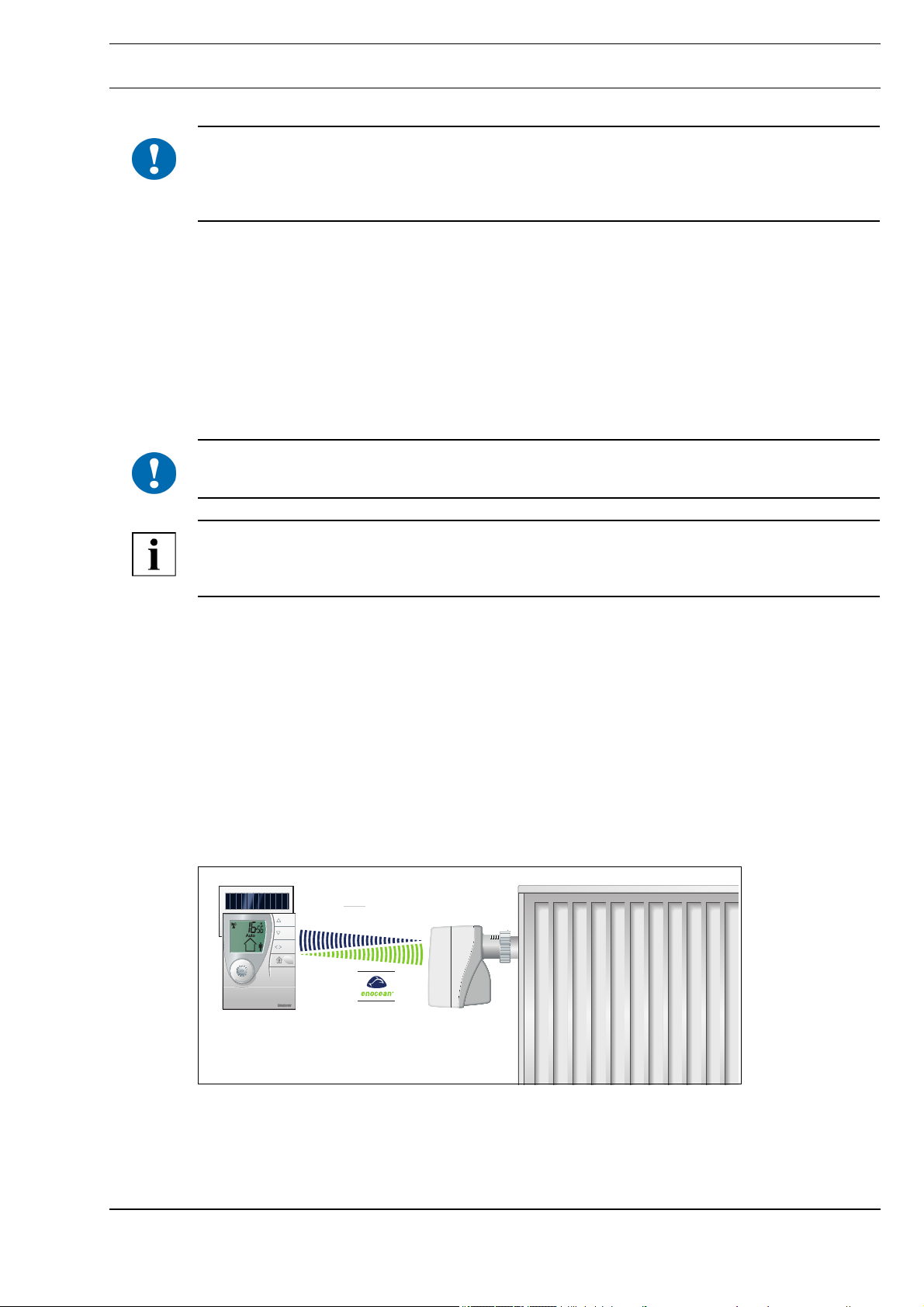
Together with the MD15-FTL radio actuator, the RPW404P-FTL room control
module constitutes a functional unit for easy room temperature control.
The following EnOcean Equipment Profiles (EEP) are supported:
■ EEP D2-10-30 *
* You can find information about the protocol description on the EnOcean
Technology website http://www.enocean-alliance.org/en/enocean_standard/
RPW404P-FTL
Änderungen vorbehalten - Contents subject to change - Sous réserve de modifications - Reservado el derecho a modificación - Wijzigingen
voorbehouden - Con riserva di modifiche - Innehåll som skall ändras - Zmeny vyhradené - Změny vyhrazeny - Zmiany zastrzeżone - Возможны
изменения - A változtatások jogát fenntartjuk - ؍⮉ᵚ㓿䙊⸕㘼᭩ࣘⲴᵳ࣋
Kieback&Peter GmbH & Co. KG
Tempelhofer Weg 50, 12347 Berlin/Germany
Telefon: +49 30 60095-0, Telefax: +49 30 60095-164
www.kieback-peter.de, info@kieback-peter.com
A
Page 2

Datasheet 1.10-65.030-01-EN Issue 2017-04-03
Product DescriptionRPW404P-FTL
Content Page
Important Information on Product Safety ....................................................................................................... 3
Item..................................................................................................................................................................... 5
Technical Data .................................................................................................................................................. 5
Dimensions ....................................................................................................................................................... 6
Radio Interface.................................................................................................................................................. 6
Installation ......................................................................................................................................................... 7
General installation instructions ........................................................................................................................ 7
Controls and functional components.............................................................................................................. 9
Indicators on the display................................................................................................................................ 10
Commissioning ............................................................................................................................................... 11
Switching the device on/off ............................................................................................................................. 11
“Test installation location” function.................................................................................................................. 12
Teaching in the MD15-FTL radio partner on the RPW404P-FTL.................................................................... 13
Mounting .......................................................................................................................................................... 14
Removal ........................................................................................................................................................... 16
Operating level ................................................................................................................................................ 16
Setting the initial display.................................................................................................................................. 16
Setting the setpoint ......................................................................................................................................... 16
Manually switching between comfort and economy mode.............................................................................. 17
Automatically switching between comfort and economy mode.......................................................................18
Closing the valve manually ............................................................................................................................. 18
Restoring defaults ........................................................................................................................................... 18
Menu level........................................................................................................................................................ 19
Config menu.................................................................................................................................................... 19
Setting vacation mode..................................................................................................................................... 19
Setting the time and date ................................................................................................................................ 20
Setting the 12/24 hour display......................................................................................................................... 21
Switching the temperature scale °C/°F ........................................................................................................... 22
Info menu ........................................................................................................................................................ 23
Set setpoints in Setpoint menu ....................................................................................................................... 24
Service level .................................................................................................................................................... 24
Messages ......................................................................................................................................................... 28
Status messages............................................................................................................................................. 28
Malfunction messages .................................................................................................................................... 30
A
Page 2 / 30
Page 3
Issue 2017-04-03
Important Information on Product Safety
Safety instructions
This data sheet contains information on installing and commissioning the product “RPW404P-FTL”.
Read this product description prior to installation, commissioning or operation. No previous special
knowledge is required to commission and operate this product.
If you have any questions that are not resolved by this data sheet, you can obtain further information
from the supplier or manufacturer.
If the product is not used in accordance with this data sheet, intended use could be impaired.
Unauthorized conversion and modifications to the device are not permitted for safety reasons and will
result in the loss of all claims against the manufacturer.
The applicable local regulations must be observed when installing and using the device.
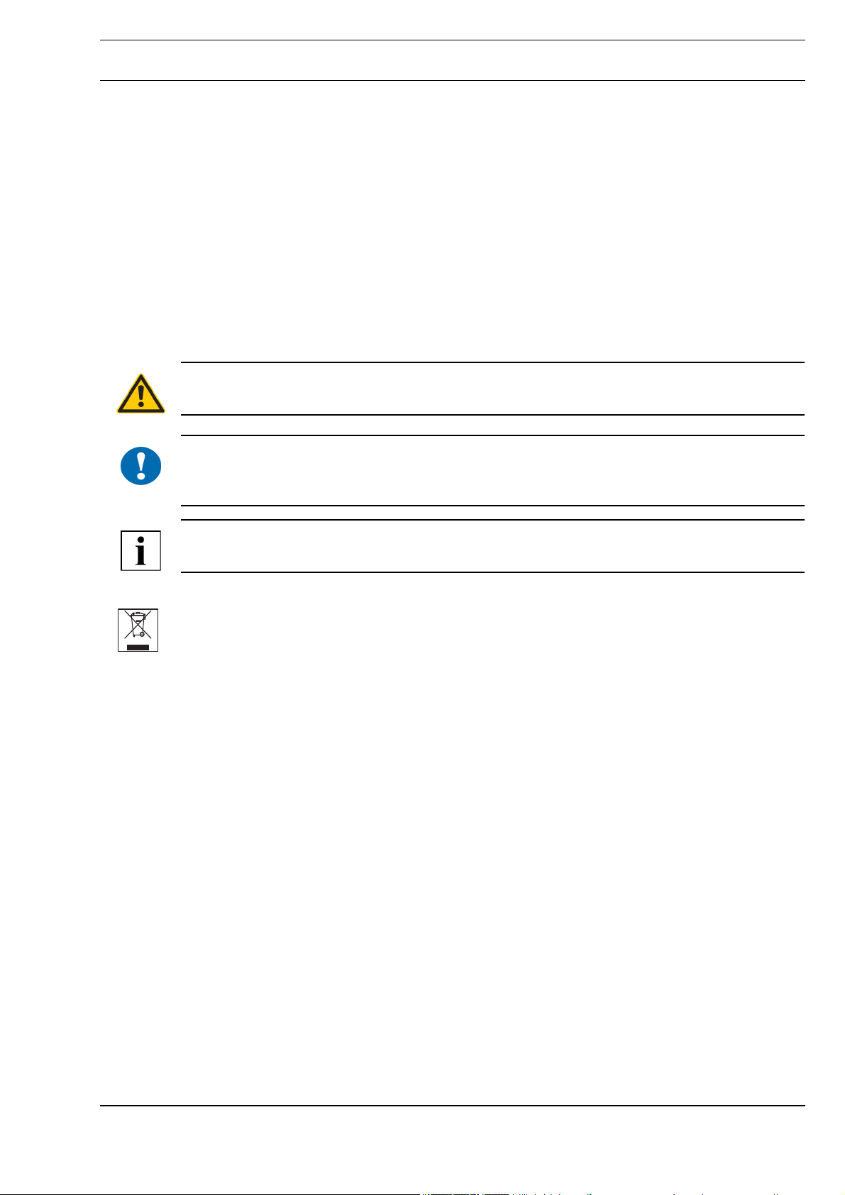
Meaning of the symbols
WARNING
Indicates a hazard of medium risk which can result in death or severe bodily injury if it is not avoided.
Datasheet 1.10-65.030-01-EN
RPW404P-FTLProduct Description
!
CAUTION
Indicates a hazard of medium risk which can result in material damage or malfunctions if it is not
avoided.
NOTE
Indicates additional information that can simplify the work with the product for you.
Notes on disposal
In accordance with the applicable laws and directives of the European Union countries, the product
should not be disposed of with household waste. This ensures environmental protection and
sustainable recycling or raw materials.
Private users should contact their local retailer or their local authority for information regarding
environmentally safe recycling of old appliances.
Commercial users should contact their supplier and observe the conditions of the purchase
agreement. This device may not be disposed of together with other commercial waste.
Page 3 / 30
A
Page 4
Datasheet 1.10-65.030-01-EN Issue 2017-04-03
Product DescriptionRPW404P-FTL
Care instructions
The room control module should be cleaned with due care. Moisture must not be allowed to enter the
housing.
CAUTION
!
Housing with a sensitive surface.
Shocks and abrasive cleaning materials can lead to scratches and a dulling of the surface.
Remove the protective foil only after you have finished all work.
Do not use any abrasive cleaning materials or cleaning products to clean the device. Clean the
housing with a moist, lint-free cloth.
NOTE
This device contains a humidity sensor. This humidity sensor is influenced by chemical substances
in the air that can be produced, for example, due to the evaporation of cleaning and care products
used to clean the room.
NOTE
The operating modes described here only apply for the self-learning room control consisting of:
- MD15-FTL radio actuator and
- RPW404P-FTL room control module.
Other radio partners, e.g. gateways, can generate other functions.
Comfort mode: Operating mode for a room that is in use (usage status: “Present”). The setpoint for
comfort mode is used as the basis for control.
Economy mode: Energy-saving operating mode (usage status: “Absent”) for a room that is not in
use. The setpoint for economy mode is used as the basis for control.
A
Page 4 / 30
Page 5

Issue 2017-04-03
Item
RPW404P-FTL Room control module with temperature sensor with SolarRadio technology, inte-
Technical Data
Nominal voltage Dual power supply consisting of a solar cell and an internal energy stor-
Measured quantity Room temperature in homes or offices
Measuring system Temperature sensor:
Measuring range 0 °C to 50 °C
Measuring tolerance Typically ±0.3 K
Display LCD display:
Controls
Datasheet 1.10-65.030-01-EN
RPW404P-FTLProduct Description
grated bidirectional EnOcean wireless interface.
Automatic determination of the utilization time profile/heating profile in the room for
automatic control of comfort mode and economy mode.
For self-learning, energy self-sufficient and occupation-dependent control of the
room temperature in conjunction with the MD15-FTL radio actuator.
age unit with priority management
additional internal energy source uses 2 3.6 V AA lithium batteries
- Integrated digital sensor
Occupancy sensor:
■ room temperature, date or time, as selected
■ Status indicators
■ Occupancy button: manually switch between comfort
mode/economy mode
- Integrated PIR (“Passive infrared”) sensor
■ Directional button up: increase value
■ Directional button down: reduce value
■ Shift button: for selecting menus or displays
Interfaces EnOcean® radio interface:
■ Radiogram: EnOcean radiogram, bidirectional
■ Frequency: 868.3 MHz
■ Duty cycle: < 1%
■ Cyclic transmission/reception intervals
Communication cycle 10 min
Transmission power < 10 mW
Illumination strength Min. 150 lux recommended
Operating range Radio:
Occupancy sensor:
Housing Plastic housing, RAL 9010 (pure white), 7001
Other colors on request
Protection class III
Degree of protection IP30
Ambient temperature 0..50 °C
Ambient humidity During operation: 20..85% r.h., non-condensing
Out of operation: 5..90% r.h., non-condensing
Mounting Flexible mounting using screws or adhesive
Approx. 30 m in buildings (depending on building
structure)
Approx. 10 m
Page 5 / 30
A
Page 6
Datasheet 1.10-65.030-01-EN Issue 2017-04-03
Product DescriptionRPW404P-FTL
Maintenance Maintenance-free
Weight 0.22 kg
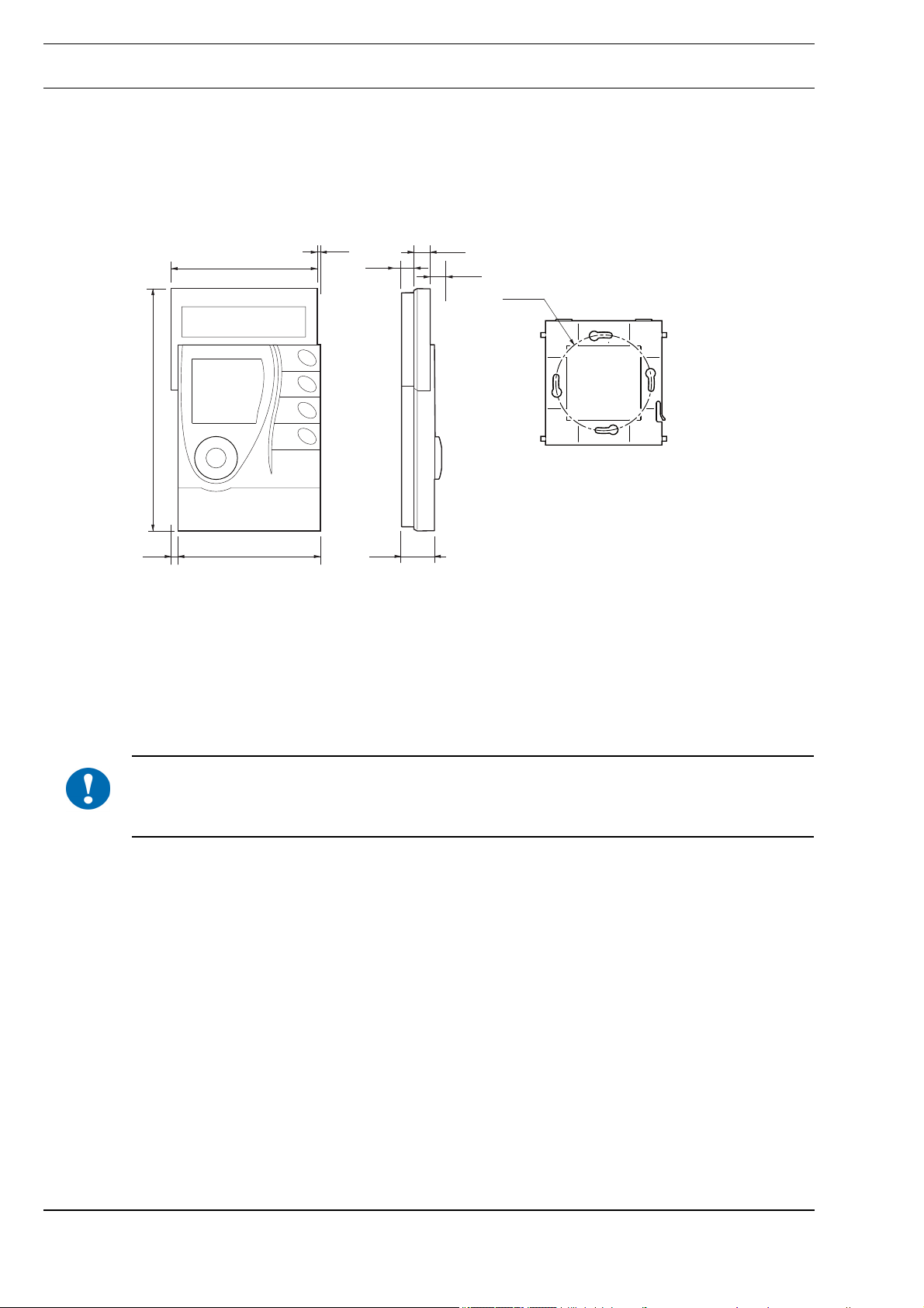
Dimensions WxHxD in mm: 90 x 153.7 x 26.7
Dimensions
Radio Interface
The radio communication with the radio partner is cyclical, bidirectional and includes an intelligent
synchronization process.
If the radio communication between the room control module and the radio partner is interrupted, an
internal resynchronization algorithm starts automatically.
Radio interference is indicated on the screen by corresponding icons (see page 28).
153,7
91,6
90,0
2,5
7,0
19,74,1
10,5
9,2
R 30,0
!
CAUTION
This product uses only EnOcean wireless telegrams.
Only devices that support the EncOcean radio standard can be used as radio partners.
A
Page 6 / 30
Page 7
Issue 2017-04-03
Installation
CAUTION
!
General installation instructions
!
This product description describes the specific settings and functions of the RPW404P-FTL room
control module. In addition to these instructions, the product description of the radio partner must also
be observed.
It is not always possible to freely select the installation location of devices which communicate
wirelessly, as radio data transmission is influenced to a greater or lesser extent by structural or spatial
factors.
In order to establish operational and reliable communication paths, the following aspects must be
considered before and during planning:
■ Structural factors restrict the transmission ranges which can be reached. Building materials and
screening elements (e.g. suspended ceiling elements, installation shafts, fire doors, etc.) must be
taken into consideration during planning.
CAUTION
Elevated humidity increases natural signal damping.
Datasheet 1.10-65.030-01-EN
RPW404P-FTLProduct Description
NOTE
Recommendation: Plan radio paths horizontally on a single level with max. 30 m between the
trasmitting and receiving modules.
■ Designed only for use in rooms.
■ Observe minimum distances to potential sources of interference.
- Min. 0.5 m to high-frequency sources of interference (such as microwaves, transformers or
computers)
- Min. 0.5 m to transmitters of other radio systems (such as a cordless telephone or headphones)
- Min. 0.1 m to metal and door frames
■ Minimize the effect of wall thickness (for example partition walls or room dividers) by ensuring that
the radio signal passes through the walls at as close to a right angle as possible.
■ Do not select installation locations in the radio shadow of screening building parts/structures No
direct reception possible.
■ Where the device is installed at the limits of reliability, change the position of the transmitter/
receiver slightly if possible (reduce overlapping effects of radio waves).
Page 7 / 30
A
Page 8
Datasheet 1.10-65.030-01-EN Issue 2017-04-03
Product DescriptionRPW404P-FTL
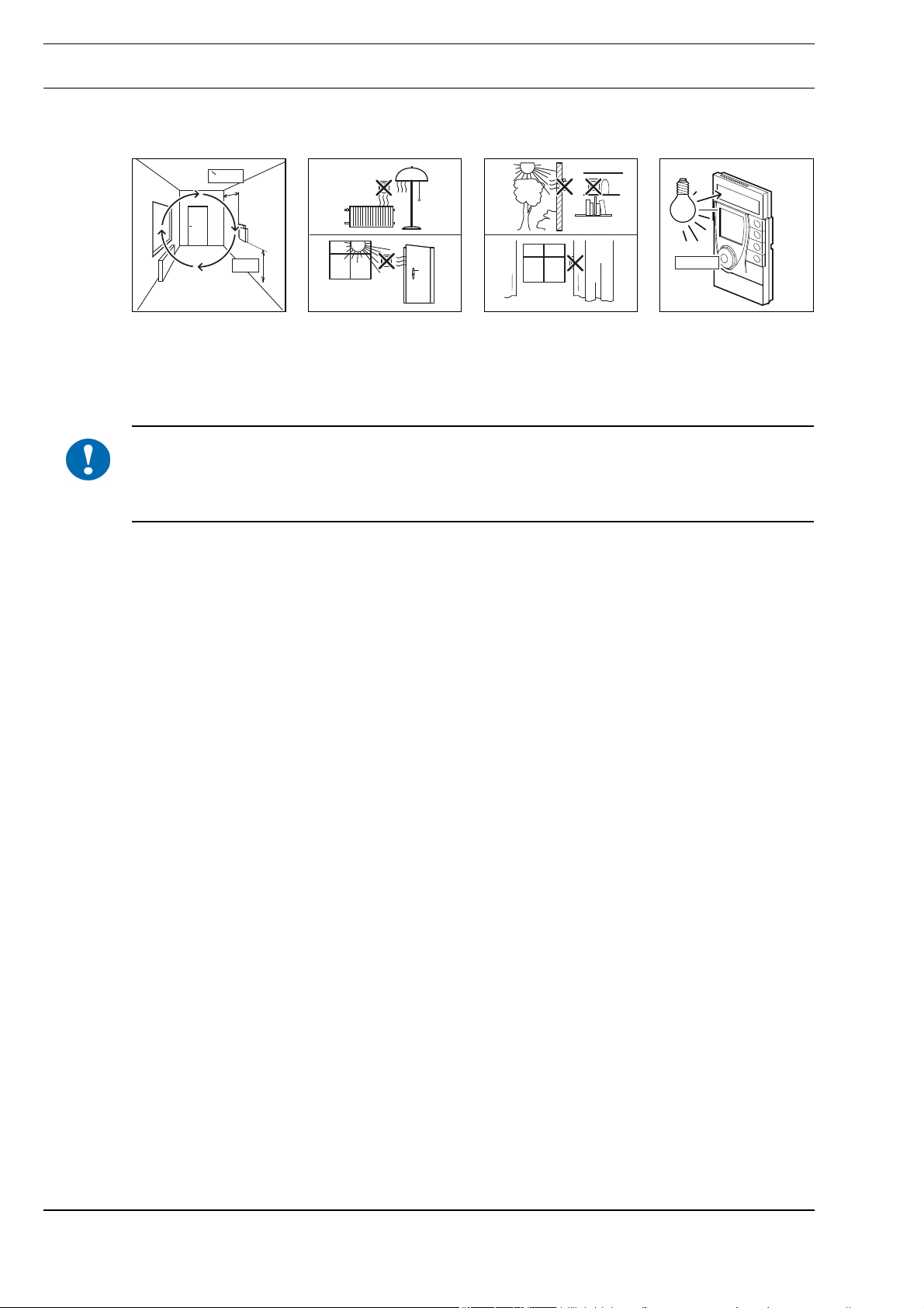
■ The room control module should be installed in a location where it is exposed to the air circulation
in the room so that it can quickly and accurately record the room temperature.
= 0,5m
>
150 Lux
!
1,5m
■ As a result of the autonomous operation and wireless installation of RPW404P-FTL, the selected
installation location can be changed and optimized at any time without additional effort.
The installation location must have sufficient lighting; using the device in unlit rooms (such as interior
kitchens/bathrooms) shortens long-term functionality.
The solar cell is optimized for indoor use and it works particularly efficiently with diffuse lighting.
CAUTION
Prolonged illumination at high intensities, e.g.
- direct sunlight or
- artificial light (such as halogen emitters) can cause damage to the solar cell.
A
Page 8 / 30
Page 9
Issue 2017-04-03
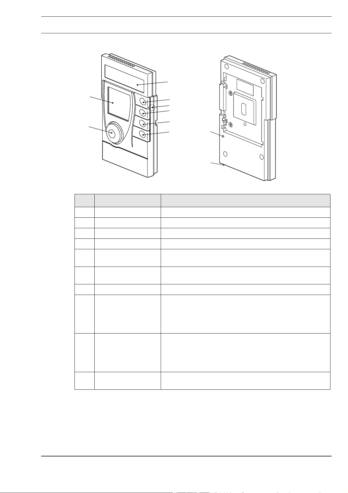
Controls and functional components
Datasheet 1.10-65.030-01-EN
RPW404P-FTLProduct Description
03
01
02
Item Designation Explanation
01 Display Displays information regarding the current status
02 Occupancy sensor Detects presence/absence for the utilization time profile
03 Solar cell Generates energy for the room control module
04 Directional button up To set: increase value
05 Magnetic contact
(below the housing)
04
05
06
07
08
For selecting the service level, see p. 24
09
10
06 Directional button
down
07 Shift button For selecting the display or menus
08 Occupancy button - Switching between comfort mode/economy mode,
09 Setting button - Switches the room control module on (together with the
10 Service connection
(underside)
To set: reduce value
see page17
- For switching the RPW404P-FTL on/off ( ith the setting
button); see page 11
- For setting functions
occupancy button), see page 11
- Starts the login process; see page 13
- Resets the room control module to factory settings,
see page 18
For authorized service technicians only
Page 9 / 30
A
Page 10

Datasheet 1.10-65.030-01-EN Issue 2017-04-03
Product DescriptionRPW404P-FTL
Indicators on the display
01
02
03
04
10
05 06 07 08 09
Item Icon/display Explanation
01 Time The information field displays the time (HH:mm)
02 Information field Display of the room temperature, date, time (= initial display, can be
03 Windows Rapid temperature drop detected
04 Message Status or malfunction messages present
05 Battery Room control module energy storage unit charging state < 30%
11
configured) or messages
17
16
15
14
13
12
06 Actuators Teach-in-modes for actuators active
07 Display lock Buttons are not responsive
08 Occupancy Occupancy sensor is active (test installation location), detected pres-
ence/absence and vacation mode
09 Auto Learned utilization time profile is active, automatic mode
10 Bars Displays the field strength quality of the receiving wireless signal,
only in the Info menu
11 Gateway Remote access via the EnOcean system gateway, teach-in-modes
for gateway active
12 Antenna Status of the radio connection
13 Vacation mode This icon appears on the display when vacation mode is activated
14 Sun The solar cell is active (test installation location).
Summer mode is active
15 PM Afternoon time, if the 12 hour display is activated
16 Fahrenheit Information field displays the temperature in degrees Fahrenheit (°F)
17 Degrees Celsius Information field displays the temperature in degrees Celsius (°C)
A
Page 10 / 30
Page 11

Issue 2017-04-03
Commissioning
Switching the device on/off
■ Switching on
The device is delivered in storage mode (switched off).
All functions are deactivated and the device does not consume any power. The energy storage unit
has been fully charged at the factory for initial commissioning.
► Press the “Occupancy button (02)” and the “Setting button (01)” simultaneously for 5 seconds.
The display is activated. The icons “Sun”, “Occupancy” and the text “InSt” appear.
The occupancy sensor and the solar cell are active. (= installation/commissioning mode for
evaluating the installation location).
01
02
Datasheet 1.10-65.030-01-EN
RPW404P-FTLProduct Description
(01) Setting button
(02) Occupancy button
NOTE
The “Test installation location” function remains active as long as the text “InSt” is displayed (see
page 12).
The room control module switches off again if a radio partner is not taught-in within 15 minutes.
■ Switching off
The room control module must be decommissioned (switched off) before transportation or storage.
The device does not consume any power and is sufficiently charged when recommissioned.
► Press the “Setting button (01)” for 5 seconds.
The text “Res” briefly appears on the display.
The display goes completely blank.
Or
► Run the “Restore default settings and switch off room control module” on the service level; see
page 24.
NOTE
The taught-in radio partners are then deleted and the room control module is reset to the default
settings.
Page 11 / 30
A
Page 12

Datasheet 1.10-65.030-01-EN Issue 2017-04-03
Product DescriptionRPW404P-FTL
“Test installation location” function
The room control module provides assistance in selecting the optimum installation location.
This function is active after switching on the device (see the “Switching the Device On/
Off” section page 11), provided a radio partner has not been registered (for a
maximum of 15 minutes).
The text “InSt” is displayed.
► Switch on the room control module, see p. 11.
The display switches on. Symbols "Sun“ and "Occupancy“ and the text "InSt" are displayed. The
occupancy sensor and the solar cell are active.
► Position the room control module at the potential installation location.
► Check the “Sun” icon on the display.
► Move about in the room and check the “Occupancy” icon.
Evaluation Display
Installation location
good
Installation location
bad
► Once a suitable installation location has been found, the room control module can be mounted
and commissioned.
NOTE
If a radio partner has not been taught-in after 15 minutes, the room control module automatically
switches off.
NOTE
If the energy storage unit is empty, the “Sun” icon will not appear even if the location is good. The
energy storage unit must be charged first. Charge the energy storage unit by placing the room control
module in a source of light for two hours (day light or artificial light, but not direct sun light).
Occupancy sensor
The room control module automatically detects a presence in the room with its occupancy sensor.
Depending on the distance, the range of movement in the detection area is important. The further a
person is away from the occupancy sensor, the greater the movement must be.
The “Sun” icon is permanently displayed and
the “Occupancy” icon switches from “Person inside the house” to “Person outside the house” and back again
The “Sun” icon is not displayed or
the “Occupancy” icon does not switch to “Person inside the house” and
remains unchanged.
1,5 m
0 m 1 m
A
2 m 3 m 4 m 5 m 8 m7 m 9 m6 m
Page 12 / 30
Page 13

Issue 2017-04-03
Teaching in the MD15-FTL radio partner on the RPW404P-FTL
CAUTION
!
This product description describes the specific settings and functions of the RPW404P-FTL. In
addition to these instructions, the product descriptions of the radio partners must also be observed.
Up to four MD15-FTL wireless small actuators can be taught-in on the room control module.
► Switch on the room control module, see page 11.
► Press the Setting button (01) briefly.
The text “SERV” briefly appears on the display, followed by
the “actuator” icon and the text “ACT”
► Press the Occupancy button for approximately 5 seconds.
The “Antenna” icon also flashes on the display.
► A teach-in radio telegram must be triggered on the MD15-FTL. Details can be
found in the documentation for the MD15-FTL.
► If multiple MD15-FTL wireless small actuators are to be taught in,
the radio teach-in telegrams must be triggered consecutively.
Datasheet 1.10-65.030-01-EN
RPW404P-FTLProduct Description
!
The number of taught-in wireless small actuators is displayed for approx. 15 seconds
following completion of the teach-in process.
Once all wireless small actuators have synchronized successfully after the teach-in
process, the “antenna” symbol is also displayed after a further 45 seconds.
Data has been exchanged between the radio partners.
All wireless small actuators must be taught-in within a single teach-in sequence.
The time between each wireless small actuator teach-in may not exceed 15 seconds.
The MD15-FTL acknowledges the start of the teach-in process with a signal tone.
Successful registration of the MD15-FTL is acknowledged with two signal tones.
If the teach-in process was successful, the “Antenna”, “Auto” and “Occupancy” icons
are displayed.
The current room temperature is displayed.
CAUTION
If the MD15-FTL wireless small actuator acknowledges registration with a downward sequence of
tones (two long tones), this means that an error has occurred and registration has failed. Start the
teach-in process again.
Page 13 / 30
The radio actuators are registered on the RPW404P-FTL. The room control module now starts to
learn the individual utilization time profile.
The room control module controls the room temperature using the default utilization time profile until
is has learned the first utilization time profile.
A
Page 14

Datasheet 1.10-65.030-01-EN Issue 2017-04-03
Product DescriptionRPW404P-FTL
Default utilization time profile:
Room used: 6:00 AM - 8:00 PM, comfort temperature
Room unused: 8:00 PM - 6:00 AM, economy temperature
NOTE
Once the procedure is complete, it is not possible to add an additional wireless small actuator.
If you want to do so, you must teach in all wireless small actuators again.
NOTE
If the room control module was already switched on, the “Switching on the device” item is skipped
and the room control module uses the utilization profile that is already taught-in.
Mounting
The room control module can be stuck to smooth, flat surfaces using the wall mount and the adhesive
pad supplied, or it can be screwed directly onto level surfaces.
Screws and wall plugs are not included in the scope of delivery of the room control module.
WARNING
Flush mounted cabling and piping at the installation location (electricity, gas, water)
Cabling and piping can be damaged by drilling.
Check the installation location for flush mounted piping and cabling, or contact a specialist.
NOTE
Position the wall mount so that the bar (1) can be easily accessed. Ensure a distance of at least 10 cm
from other objects (door frames, electrical sockets, cupboards, etc.).
NOTE
Observe the orientation of the wall mount. The bar (1) must be on the right-hand, lower side when the
device is installed, see figure 4.
Use the enclosed adhesive numbers (2) to uniquely identify the mounting location and the respective
room control module.
► Mark the room control module and the wall mount with a unique number using the enclosed
adhesive numbers (2).
A
Page 14 / 30
Page 15

Issue 2017-04-03
Datasheet 1.10-65.030-01-EN
RPW404P-FTLProduct Description
Wall mounting
- Flexible screw mounting
1
1 2 3
2
5
(1) bar (2) adhesive numbers
Wall mounting
- Flexible adhesive mounting with double-sided transparent adhesive strips
NOTE
For a permanent connection, remove any dust and grease from the adhesive surface on the wall
mount and the wall.
6
7 8
4
Page 15 / 30
1
1
5 6 7
2 3 4
A
Page 16

Datasheet 1.10-65.030-01-EN Issue 2017-04-03
Product DescriptionRPW404P-FTL
Removal
1
5
Operating level
Setting the initial display
► Briefly pressing the selector button “ ”, enables you to select the following displays:
Setting the setpoint
Using the “ ” or “ ” button, you can change the current setpoint manually.
1
■ Room temperature
■ Date
■ time, see example
The last display selected then becomes the initial display.
► Briefly press the “ ” or “ ” button.
The setpoint to be set flashes.
► Set the required setpoint using the “ ” or “ ” button.
The new selected value flashes for approx. 5 seconds. It is then
automatically confirmed and the room control module switches
to the initial display.
Manual override will also make the “Auto” icon disappear.
2 3
NOTE
The adjusted setpoint in the operating level remains active for a period of two hours.
The setpoints for comfort mode and economy mode that were set on the configuration level then
become active again and the “Auto” icon is displayed again.
A
Page 16 / 30
Page 17

Issue 2017-04-03
Manually switching between comfort and economy mode
► You can manually switch between comfort mode and economy mode and vice versa by pressing
the “Occupancy button”.
This is displayed by the comfort mode or economy mode icons. The “Auto” icon
also disappears from the display.
■ Changing from comfort mode to economy mode:
economy mode is active for 4 hours.
The utilization time profile is then active again and the “Auto” icon appears on the display.
Example 1:
Comfort temperature 20 °C, economy temperature: 16 °C
Room used: 6:00 AM - 9:00 AM and 3:00 PM - 9:00 PM
Absence set manually (by pressing the “Occupancy button) 6:00 PM - 10:00 PM
°C
Datasheet 1.10-65.030-01-EN
RPW404P-FTLProduct Description
20°C
16°C
00:00 06:00 12:00 18:00 24:00
■ Changing from economy mode to comfort mode:
comfort mode is active for 2 hours.
The utilization time profile is then active again and the “Auto” icon appears on the display.
Example 2:
Comfort temperature 20 °C, economy temperature: 16 °C
Room used: 6:00 AM - 9:00 AM and 3:00 PM - 9:00 PM
Presence set manually (by pressing the “Occupancy button) 10:00 AM - 12:00 AM
°C
20°C
16°C
h
00:00 06:00 12:00 18:00 24:00
Page 17 / 30
A
Page 18

Datasheet 1.10-65.030-01-EN Issue 2017-04-03
Product DescriptionRPW404P-FTL
Automatically switching between comfort and economy mode
Automatic switching between comfort or economy mode is performed according to the utilization
profile learned.
The utilization profile is generated automatically, and is continuously and dynamically adjusted and
optimized.
This is displayed by the comfort mode or economy mode icons. The “Auto” icon also
appears in the display.
Presence/absence is recorded by the occupancy sensor in order to learn the utilization profile.
The room control module continuously adapts the operating mode depending on real utilization
behavior.
Closing the valve manually
To prevent the formation of mold, it is necessary to adequately ventilate the room.
To save on heating costs, there is also an option to have the wireless small actuator close the valve.
► Press and hold the “ ” button for 5 seconds.
The “window” icon appears on the display and the “Auto” icon
disappears from the display.
The wireless small actuator closes the valve.
When the room has been sufficiently ventilated, the room temperature control switches back to
automatic mode.
► Hold down the button “ " for 5 s.
The “Window” icon disappears from the display.
NOTE
If the control has not been manually reset to automatic mode, it will be reset upon changeover to the
next day.
Restoring defaults
When the defaults are restored, the learned utilization time profile and the wireless connections are
deleted and all settings are restored to the factory settings.
► Press the “Setting button” for 5 seconds.
The text “RES” appears briefly and the display goes blank.
The room control module is now switched off.
A
Page 18 / 30
Page 19

Issue 2017-04-03
Menu level
Config menu
Datasheet 1.10-65.030-01-EN
RPW404P-FTLProduct Description
NOTE
If no settings are made within approx. 5 seconds, the individual setting functions are exited and saved
as required.
The following functions are available in the Config menu:
■ Setting vacation mode
■ Setting the time and date
■ Setting the 12/24 hour display
■ Switching the temperature scale °C/°F
Setting vacation mode
► Hold down the “Occupancy button” for 5 seconds.
The text “Menu” briefly appears on the display, followed by “SETP”.
► Release the “Occupancy button”.
► Briefly press the “Occupancy button” repeatedly or the “ ”
button to select the “Conf” function.
► Hold down the “Occupancy button” for 5 seconds.
► Release the “Occupancy button”.
The “Set vacation” menu item appears in the display.
► Hold the “Occupancy button” down for 5 seconds or
press the “ ” or “ ” button.
The value being set flashes.
► Briefly pressing the “Occupancy button” or the “ ” or “ ” button
sets the vacation duration to a maximum of 31 days.
Briefly pressing the “Occupancy button” or the “ ” button increases the current
value by +1. Briefly pressing the “ ” button reduces the current value by -1.
Setting "00d" = 0 days deletes all previous settings.
Page 19 / 30
The setting is accepted after 5 seconds of no entry being made. Vacation mode comes
into effect upon the end of the day at 0.00 hours.
The display switches back to initial display and the “suitcase” icon appears for
vacation mode.
A
Page 20

Datasheet 1.10-65.030-01-EN Issue 2017-04-03
Product DescriptionRPW404P-FTL
When vacation mode is active, the room control module is in economy mode and
control is based on the setpoint for vacation mode, see page 24.
The display also shows the (house without little man) symbol.
At the end of vacation mode, the comfort mode becomes active at 0.00 for a duration
of 6 h.
Delete vacation mode
To abort vacation mode, you must set vacation duration to "00d" = 0 days.
The settings procedure is the same as previously described.
Setting the time and date
The hour, minutes, year, month and day can be set in sequence.
The values to be set flash.
► Hold down the “Occupancy button” for 5 seconds.
The text “Menu” briefly appears on the display, followed by “SETP”.
► Release the “Occupancy button”.
► Briefly press the “Occupancy button” repeatedly or the “ ”
button to select the “Conf” function.
► Hold down the “Occupancy button” for 5 seconds.
The “Set vacation” menu item appears in the display.
► Briefly press the “Occupancy button” repeatedly or the “ ”
button to select the “TIME” button.
► Hold the “Occupancy button” down for 5 seconds or
press the “ ” or “ ” button.
The display switches to the menu item for setting the “Time and date”.
The value being set flashes.
► Press the “Occupancy button” or the “ ” or “ ” button once to
confirm the hour displayed or press it several times/hold it down
until the required set value is reached.
► Release the “Occupancy button” or the “ ” or “ ” button.
The next value to be set will start to flash after approximately 3 seconds.
The procedure for setting the minutes, year, month and day is the same as that for
setting the hour.
NOTE
Press the “Occupancy button” or the “ ” button to increase the current value by +1.
Holding down the “Occupancy button” or the “ ” button increases the value sequentially.
A
Page 20 / 30
Page 21

Issue 2017-04-03
Datasheet 1.10-65.030-01-EN
RPW404P-FTLProduct Description
Once the last value for the day has been entered, this is indicated by a moving line on
the display.
The time and date settings are complete and are saved.
The display then switches to the initial display.
NOTE
If no input is made for approx. 10 seconds, the display returns to the initial display. Any settings that
were previously made are not saved.
Daylight saving time switching occurs automatically according to Central European standards.
Default setting: current CET Central European Time
Setting the 12/24 hour display
► Hold down the “Occupancy button” for 5 seconds.
The text “Menu” briefly appears on the display, followed by “SETP”.
► Release the “Occupancy button”.
► Briefly press the “Occupancy button” repeatedly or the “ ”
button to select the “Conf” function.
► Hold down the “Occupancy button” for 5 seconds.
The “Set vacation” menu item appears in the display.
► Briefly press the “Occupancy button” repeatedly or the “ ”
button to select the “24h” function.
► Release the “Occupancy button” or the “ ” button.
► Hold down the “Occupancy button” or the “ ” button for 5 seconds;
the 12h display is then set.
After approx.3 seconds, the display returns to the initial display.
When the 12 hour display is activated, an additional PM is shown in the display in the
afternoon.
Default setting: 24h
Page 21 / 30
A
Page 22

Datasheet 1.10-65.030-01-EN Issue 2017-04-03
Product DescriptionRPW404P-FTL
Switching the temperature scale °C/°F
► Hold down the “Occupancy button” for 5 seconds.
The text “Menu” briefly appears on the display, followed by “SETP”.
► Release the “Occupancy button”.
► Briefly press the “Occupancy button” repeatedly or the “ ”
button to select the “Conf” function.
► Hold down the “Occupancy button” for 5 seconds.
The “Set vacation” menu item appears in the display.
► Briefly press the “Occupancy button” repeatedly or the “ ” button to select the
“TEMP” function.
► Release the “Occupancy button” or the “ ” button.
► Hold down the “Occupancy button” or the “ ” button for 5 seconds;
the temperature scale °F is then set.
After approx. 3 seconds, the display returns to the initial display and the
temperature is displayed in °F only.
Default setting: °C
A
Page 22 / 30
Page 23

Issue 2017-04-03
Info menu
Datasheet 1.10-65.030-01-EN
RPW404P-FTLProduct Description
The following information is displayed in the Info menu:
■ Status message
■ Display of the taught-in radio partners
– Wireless address of the taught-in radio partners
– Position indication of the taught-in wireless small actuators
– Field strength of the receiving wireless signal
► Hold down the “Occupancy button” for 5 seconds.
The text “Menu” briefly appears on the display, followed by “SETP”.
► Hold down the “Occupancy button” for 5 seconds.
► Briefly press the “Occupancy button” repeatedly or the “ ” button to select the
“Info” function.
► Hold down the “Occupancy button” for 5 seconds.
► Briefly press the “Occupancy button” repeatedly or the “ ” button
to display the aforementioned information one after the other.
If you do not take any other actions, the display will return to the initial display after
5 seconds.
Status message
The status message is displayed. For more information, see page 28.
Display of the taught-in radio partners
If no radio partners have been taught-in, this display does not appear.
First, the number of taught-in wireless small actuators is displayed.
► Briefly press the “Occupancy button” repeatedly or the “ ” button
to display the individual information for the taught-in radio artners
one after the other.
1
2
The wireless IDs of the taught-in radio partners are displayed.
The last four hexadecimal digits of the wireless ID of the taught-in radio partner are
displayed.
For the wireless small actuators, the position indicator (1) is also displayed in the form
of a bar diagram.
The display (2) also indicates which wireless small actuator or EnOcean gateway is
currently shown.
Page 23 / 30
■ = taught-in EnOcean gateway
■ = taught in wireless small actuator 1 to 4
■ = trend display of the field strength of the receiving radio signal
A
Page 24

Datasheet 1.10-65.030-01-EN Issue 2017-04-03
Product DescriptionRPW404P-FTL
Set setpoints in Setpoint menu
The setpoints for comfort mode, economy mode and vacation mode are set here.
► Hold down the “Occupancy button” for 5 seconds.
The text “Menu” briefly appears on the display, followed by “SETP”.
► Release the “Occupancy button”.
► Hold down the “Occupancy button” for 5 seconds.
► Release the “Occupancy button”.
► Press the “Occupancy button” or the “ ” button to select the setting for the
required setpoint – comfort mode, economy mode or vacation mode.
Comfort mode setpoint
► Briefly press the “Occupancy button” or the “ ” or “ ” button
to set the required setpoint.
The setpoint for comfort mode continues to flash while settings are being
made.
Default setting: Comfort mode 22 °C
Economy mode setpoint
Vacation mode setpoint
Service level
The following functions are available on the service level:
■ Teach in wireless small actuators
■ Teach in an EnOcean system gateway
■ Delete all taught-in radio partners
■ Restore default settings and switch off room control module
■ Software version display
► Briefly press the “Occupancy button” or the “ ” or “ ” button
to set the required setpoint.
The setpoint for economy mode continues to flash while settings are being
made.
Default setting: Economy mode 18 °C
► Briefly press the “Occupancy button” or the “ ” or “ ” button
to set the required setpoint.
The setpoint for vacation mode continues to flash while settings are being
made.
Default setting: Vacation mode 14 °C
A
Page 24 / 30
Page 25

Issue 2017-04-03
Datasheet 1.10-65.030-01-EN
RPW404P-FTLProduct Description
1
Using a magnet (1) or briefly pushing the setting button
switches to the service level.
► Briefly slide the magnet along the upper right-hand side of the device
(see figure) or briefly press the Setting button.
The room control module switches to the service level.
► Briefly press the “Occupancy button” repeatedly or the “ ” button
and the aforementioned functions will be offered one after the other.
If you do not take any other actions, the display will return to the initial display after
5 seconds.
Teaching in the MD15-FTL radio partner
► Hold down the “Occupancy button” for about 5 seconds and the “Teach in the
MD15-FTL radio partner
” function will run (see the “Teaching in the MD15-FTL radio partner
on the RPW404P-FTL” section on page 13).
Page 25 / 30
A
Page 26

Datasheet 1.10-65.030-01-EN Issue 2017-04-03
Product DescriptionRPW404P-FTL
Teaching in an EnOcean system gateway
► Briefly press the “Occupancy button” repeatedly or the “ ” button to select the
“GATE” function.
► Hold down the “Occupancy button” for about 5 seconds and the “Teach in an
EnOcean system gateway” function will run.
The “Antenna” icon flashes briefly on the display.
A teach-in radiogram is sent to the system gateway and
a teach-in radiogram from the system gateway is awaited.
You can find details in the documentation of the EnOcean system gateway.
The display then returns to the initial display. If the teach-in process was successful,
the wireless communication icon also appears.
NOTE
An EnOcean system gateway makes it possible to connect to a Building and Energy Management
System BEMS.
This makes it possible to generate additional functions such as:
- Visualizing operating states
- Displaying trend curves e.g. for the room temperature or humidity
- Overriding the operating modes with special utilization times such as public holidays.
NOTE
The resources of the energy source are also used when communicating with a system gateway. The
increased transmission frequency has an impact on the service life of the energy source (AA lithium
batteries), see p. 29
Deleting all taught-in radio partners
► Briefly press the “Occupancy button” repeatedly or the “ ” button
to select the “dEL” function.
► Hold down the “Occupancy button” for about 5 seconds and the “Delete all taught-in
radio partners” function will run.
NOTE
After all the taught-in radio partners have been deleted, the radio partners must be taught in again.
Otherwise, the room control module will switch off after 15 minutes.
A
Page 26 / 30
Page 27

Issue 2017-04-03
Datasheet 1.10-65.030-01-EN
RPW404P-FTLProduct Description
Restoring default settings and switching off the room control module (see also page 19)
► Briefly press the “Occupancy button” repeatedly or the “ ” button
to select the “RES” function.
► Hold down the “Occupancy button” for about 5 seconds and the “Restore default
settings and switch off room control module” function will run.
The room control module switches off. The display disappears.
NOTE
The taught-in radio partners are then deleted and the room control module is reset to the default
settings.
Software version display
► Briefly press the “Occupancy button” repeatedly or the “ ” button to select
the “Software version display” function.
The software version of internal processor 1 is displayed.
► The press the “Occupancy button” or 5 seconds.
The software version of internal processor 2 is displayed.
Page 27 / 30
A
Page 28

Datasheet 1.10-65.030-01-EN Issue 2017-04-03
Product DescriptionRPW404P-FTL
Messages
Status messages
Icon/display State Explanation
Antenna On
Off
InSt On “Test installation location” evaluation function is active
Antenna Flashes Possible to register wireless small actuators
Antenna
Er01
Antenna
Er01
Antenna
Er02
Antenna
Er02
Battery On Room control module
Er04 On Wireless small actuator (1 to 4), charge state < 30% for at
Window On Economy mode for max. 30 minutes or close the valve manu-
On
On
Off
On
On
On
Off
On
Radio connection functioning properly; Er00 is displayed in the
Info menu
Radio connection partly interrupted (> 1 hour)
At least one wireless small actuator is transmitting
Radio connection interrupted (> 1 hour)
No wireless small actuator is received
Radio connection partly interrupted (> 4 hours)
At least one wireless small actuator is received
No wireless small actuator is received
Charge state < 30%
least one wireless small actuator
On the service level, the battery icon also appears next to
each drive.
ally
Suitcase On Vacation mode activated (starts at 0.00)
On
Suitcase
Sun On
Er06 On Radio connection to EnOcean system gateway interrupted
NOTE
If the Message icon also appears in the display, you can find more information in the Info menu;
see page 23.
Radio connection
The “Antenna” displays the current state of the radio connections to the radio partners.
The status of the radio connection is monitored continuously. A message is displayed if the radio
connection status changes.
NOTE
Communication is continued automatically once the radio connection between the room control
module and the wireless small actuator is functioning properly again. “ Er01” or “ Er02” disappears and the “Antenna” icon is displayed permanently.
On
Off
Longer absence - vacation
Summer mode
System in energy saving mode
A
Page 28 / 30
Page 29

Issue 2017-04-03
Datasheet 1.10-65.030-01-EN
RPW404P-FTLProduct Description
Energy storage unit
The “Battery” icon indicates the current state of the energy storage unit of the room control module.
The room control module continuously monitors the charge state of the energy storage unit. The
“Battery” icon appears on the display if the charge state drops below 30%.
NOTE
Charge the energy storage unit by placing the RPW404P-FTL in a source of light for two hours (day
light or artificial light, but not direct sun light).
Energy source
The internal AA lithium batteries support solar operation. The resources of the energy source are only
used when the internal energy storage unit can no longer guarantee the function of the room control
module.
The service life of the AA lithium batteries depends on the transmission frequency, the aging of the
batteries and the self-discharge. They generally last for several years.
NOTE
If the “Battery” icon begins to appear in the display more and more frequently, it indicates that the AA
lithium batteries need to be replaced.
This must be carried out by an authorized service technician.
Please contact your supplier.
Rapid temperature drop
If the room control module detects a rapid drop in temperature (e.g. a window has been opened), the
radio actuator closes the valve for a maximum of 30 minutes.
The “Window” icon appears on the RPW404P-FTL display.
The rapid drop in temperature detected is not included in the learned utilization time profile.
NOTE
Press and hold the “ ” button for approx. 5 seconds to end this function early.
Extended absence
The room control module continuously monitors the room utilization. If the room control module
detects a longer absence (three days without occupancy), the utilization time profile permanently
switches to economy mode and the icon appears on the display.
If the “Occupancy button” is pressed after a longer absence, or if the room control module detects
room occupancy for a period of 20 minutes, the utilization time profile switches to comfort mode and
the learned utilization time profile becomes active again.
Summer mode
Between June 1 and August 31 of a year, the room temperature control switches to summer mode.
Room temperature control is then in economy mode.
The devices only consume a small amount of power.
The “Sun” icon appears and the “Occupancy” icon disappears.
Page 29 / 30
A
Page 30

Datasheet 1.10-65.030-01-EN Issue 2017-04-03
Product DescriptionRPW404P-FTL
Malfunction messages
Icon/display State Explanation
Antenna
Er08
Er03 On Synchronization on the RPW404P-FTL malfunctioning
Transmission function malfunctioning
The radio connection is continuously monitored. If a transmission function malfunction is detected in
the room control module, the “ Er08” icon appears on the display.
The following troubleshooting procedures can be implemented:
► Reset the room control module to factory settings (see p.18).
The " Er08” symbol disappears from the display.
► Register the radio partners again.
If the “Er08” icon appears again, it means that the room control module has a serious fault. It must
be checked by an authorized service technician.
NOTE
If the transmission function on the room control module malfunctions, the MD15-FTL enters
self-controlled mode (= emergency mode).
The temperature is controlled to a fixed setpoint of 20 °C using the integrated control function in the
wireless small actuator.
Off
On
Transmission function on the RPW404P-FTL malfunctioning
System time
The internal system time of the room control module is monitored constantly. If a system time
malfunction is detected in the room control module, the “ Er03” icon appears on the display.
► Reset the time and date (see page 20).
The “ Er03” icon disappears from the display.
If the “ Er03” icon continues to appear, it means that the room control module has a serious fault.
It must be checked by an authorized service technician.
A
Page 30 / 30
 Loading...