

Page 1
A
Quick Start Guide
Room Sensor
Valve Controller
Page 2

Page 3

3/44 | en:key
Important Information
Symbols, signal words ........................................................................ 4
Basic safety instructions ..................................................................... 5
Proper use .........................................................................................6
Wireless radio systems and health ......................................................6
Data protection .................................................................................. 6
Device Overview
Valve controller .................................................................................. 7
Room sensor ...................................................................................... 8
Commissioning
Testing the installation location ......................................................... 12
Registering the valve controller ......................................................... 14
Mounting the room sensor ................................................................ 16
Mounting the valve controller ............................................................ 18
Operation
Setting the comfort temperature ........................................................ 21
Changing to comfort mode/economy mode ........................................22
Start/change/end vacation mode ....................................................... 24
Changing the time and date .............................................................. 25
Toggling the display .......................................................................... 27
Restoring the defaults ...................................................................... 28
Switching off the room sensor, valve controller .................................. 30
Activating the service level ............................................................... 31
Messages
System status .................................................................................. 36
Malfunctions .................................................................................... 37
Other
Care, disposal, service ..................................................................... 38
Technical data .................................................................................. 39
Page 4
IMPORTANT INFORMATION
en:key | Important Information 4/44
This quick start guide will help you to ensure that your devices always run reliably. You
must read this guide and all other applicable documents before using the devices.
No previous special knowledge is required to commission and operate these devices. For
issues that cannot be resolved using this guide, use other documents or contact an
authorized service technician.
Other documents can be downloaded from the website www.enkey.de or
directly via the QR code.
Other documents: Quick start guide, brief overview, assembly instructions,
declarations of conformity
» Symbols, signal words
The safety information and notices in this quick start guide are marked by graphical
elements.
Symbols Description
Caution
Safety information that helps to prevent property damage.
Basic safety instruction that guarantees the safe use and operational reliability of the devices.
Page 5
5/44 Important Information | en:key
» Basic safety instructions
Read and observe the following safety instructions before using the devices. This will
reduce the risk of personal injury and damage to the environment or the devices.
Symbol Description Symbol Description
Information that prevents malfunctions and potential extra
work.
General information.
Information on disposing of the
electronics.
Information on location and
positioning.
Information on
recycling.
This quick start guide is an integral part of the devices and must be kept eas-
ily accessible at all times.
If the devices are not used according to the instructions in this quick start
guide, the existing protective measures will be impaired.
Unauthorized opening, conversion or modification of the devices is not per-
mitted for safety reasons, and will result in the loss of all claims against the
manufacturer.
Caution
Housing with a sensitive surface.
Shocks and abrasive cleaning materials can lead to scratches and a dulling.
► Remove the protective foil only after you have finished all work.
Clean using a moist, lint-free cloth.
Do not use any abrasive cleaning materials or cleaning products.
Page 6

en:key | Important Information 6/44
» Proper use
The en:key room set devices are intended solely for the purpose of controlling the room
temperature in closed, indoor rooms (e.g. residential and business rooms). The en:key
room set is not suitable for the operation of underfloor heating. Each room requires a
separate room sensor.
» Wireless radio systems and health
The Institute for Social-Ecological Research and Education (ECOLOG) has issued an
expert report confirming that the high-frequency emissions from wireless radio switches
and sensors with EnOcean technology are significantly lower than those from equivalent
conventional light switches. Other devices, such as wireless telephones, are higher than
those of wireless radio switches with EnOcean technology by a factor of 1500.
» Data protection
To regulate room temperature according to the user's requirements, en:key only uses
aggregate information. En:key processes this information in accordance with applicable
data protection laws. The room sensor can be reset to the factory settings at any time using
the “Restore factory settings” function. All information such as the learned heating time
profile and the radio partners is deleted permanently when factory settings are restored.
→ Restoring the defaults (S.28)
Page 7
DEVICE OVERVIEW
7/44 Device Overview | en:key
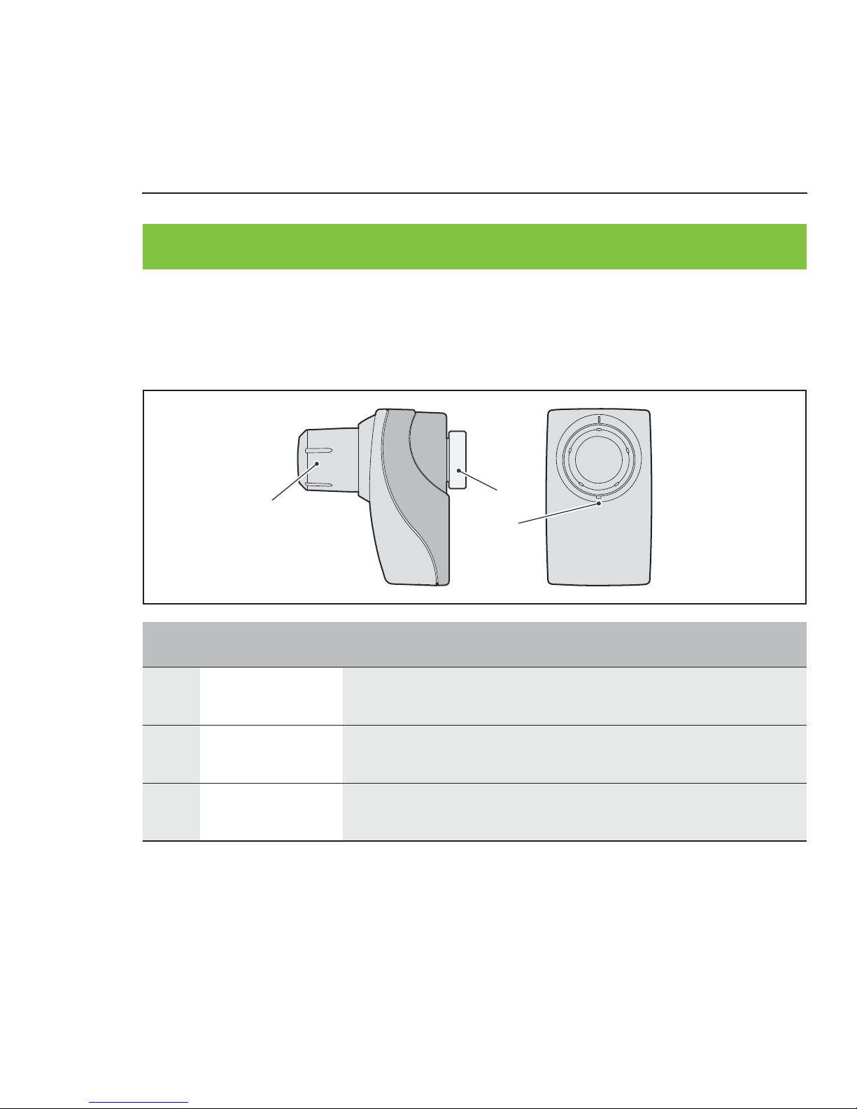
» Valve controller
03
01
02
Operating components, functional components
Item Designation Explanation
01 Rotary knob Adjusts comfort temperature
→ Setting the comfort temperature (S.21)
02 Octagon nut Fastens the valve controller to the valve
→ Mounting the valve controller (S.18)
03 Registration
button
Registers the valve controller
→ Registering the valve controller (S.14)
Page 8
en:key | Device Overview 8/44
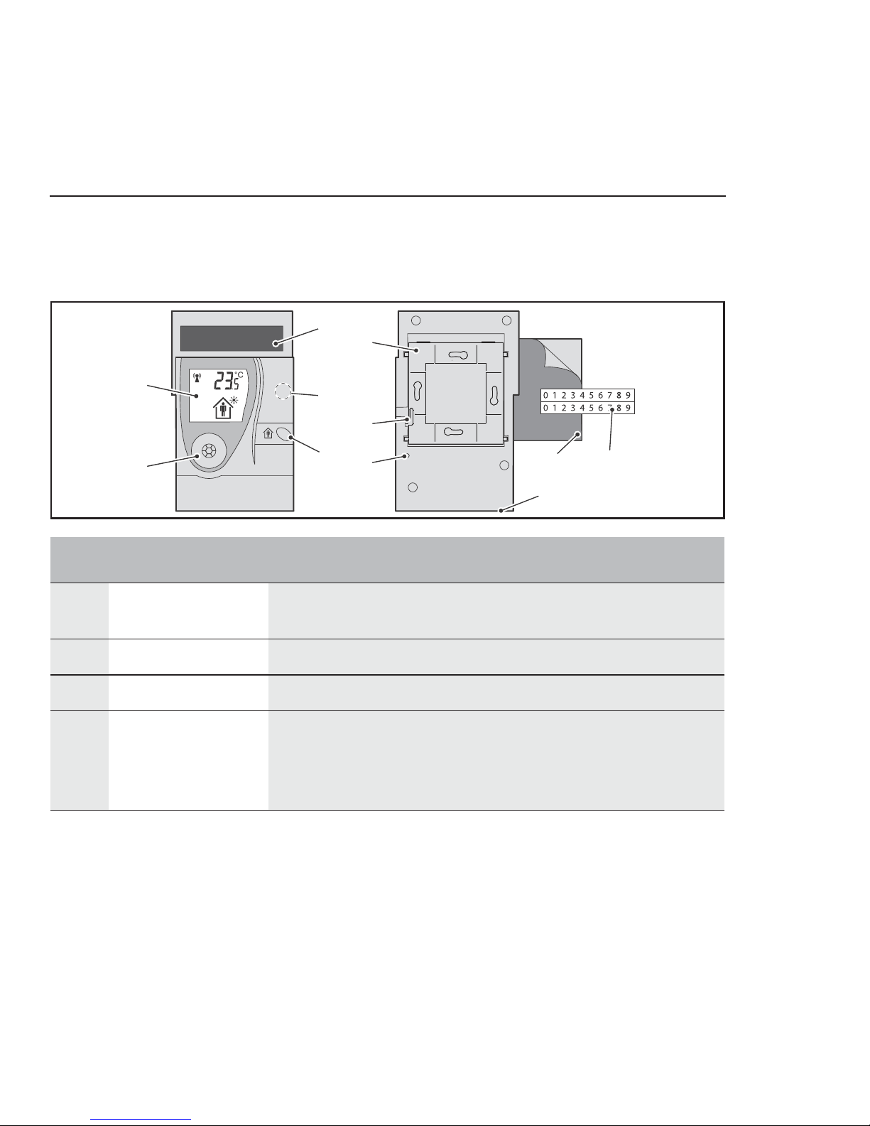
» Room sensor
03
05
04
09
11
01
02
08
06
07
10
Operating components, functional components
Item Designation Explanation
01 Display Shows information on the current state of the room sensor
and valve controller
02 Occupancy sensor Detects presence/absence for the heating time profile
03 Solar cell Generates energy for the room sensor.
04 Magnetic contact Switches the display between room temperature/time
Starts the service level
→ Toggling the display (S.27)
→ Activating the service level (S.31)
Page 9

9/44 Device Overview | en:key
05 Occupancy button Switches the room sensor on (with setting button)
Temporarily changes between comfort mode/economy
mode
Sets time and date, vacation mode
→ Testing the installation location (S.12)
→ Changing to comfort mode/economy mode (S.22)
→ Changing the time and date (S.25)
→ Start/change/end vacation mode (S.24)
06 Wall mount Fastens the room sensor to the wall
→ Mounting the room sensor (S.16)
07 Holding bar Holds the room sensor in place on the wall mount
08 Setting button Switches room temperature on (with occupancy button)
Starts registration procedure
Resets room controller to defaults
→ Testing the installation location (S.12)
→ Registering the valve controller (S.14)
→ Restoring the defaults (S.28)
09 Adhesive pad Bonds the wall mount to the wall
→ Mounting the room sensor (S.16)
10 Adhesive numbers Identifies room sensor and wall mount
→ Mounting the room sensor (S.16)
11 Service
connection
For authorized service technicians only (underside)
Item Designation Explanation
Page 10
01
02
03
04
05
06
07
08
09
11
10
en:key | Device Overview 10/44
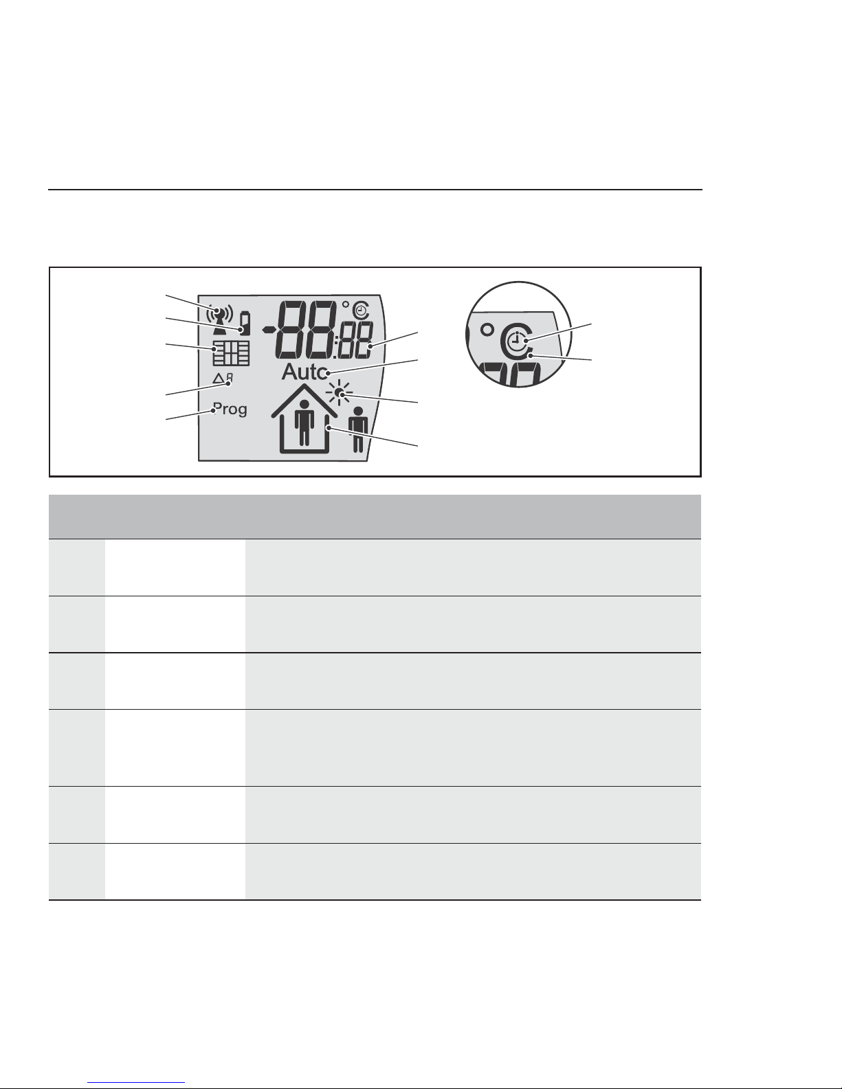
Display
Item Designation Explanation
01 Antenna Wireless connection system status
→ System status (S.36)
02 Battery Energy storage unit system status
→ System status (S.36)
03 Windows Rapid temperature drop detected
→ System status (S.36)
04 Code Status messages
→ System status (S.36)
→ Malfunctions (S.37)
05 Prog Valve controllers can be registered
→ Registering the valve controller (S.14)
06 Information field Display of the room temperature, time or messages
→ Toggling the display (S.27)
Page 11

11/44 Device Overview | en:key
07 Auto Heating time profile is active (default/learned)
→ Registering the valve controller (S.14)
08 Sun Solar cell is active (test installation location)
en:key room set is in summer mode
→ Testing the installation location (S.12)
→ System status (S.36)
09 Occupancy Occupancy sensor is active (test installation location),
Detected presence/absence
Vacation mode is active
→ Testing the installation location (S.12)
→ Changing to comfort mode/economy mode (S.22)
→ Start/change/end vacation mode (S.24)
10 Clock The information field displays the time (hh:mm)
11 Degrees Celsius The information field displays the room temperature (°C).
Item Designation Explanation
Page 12
COMMISSIONING
en:key | Commissioning 12/44
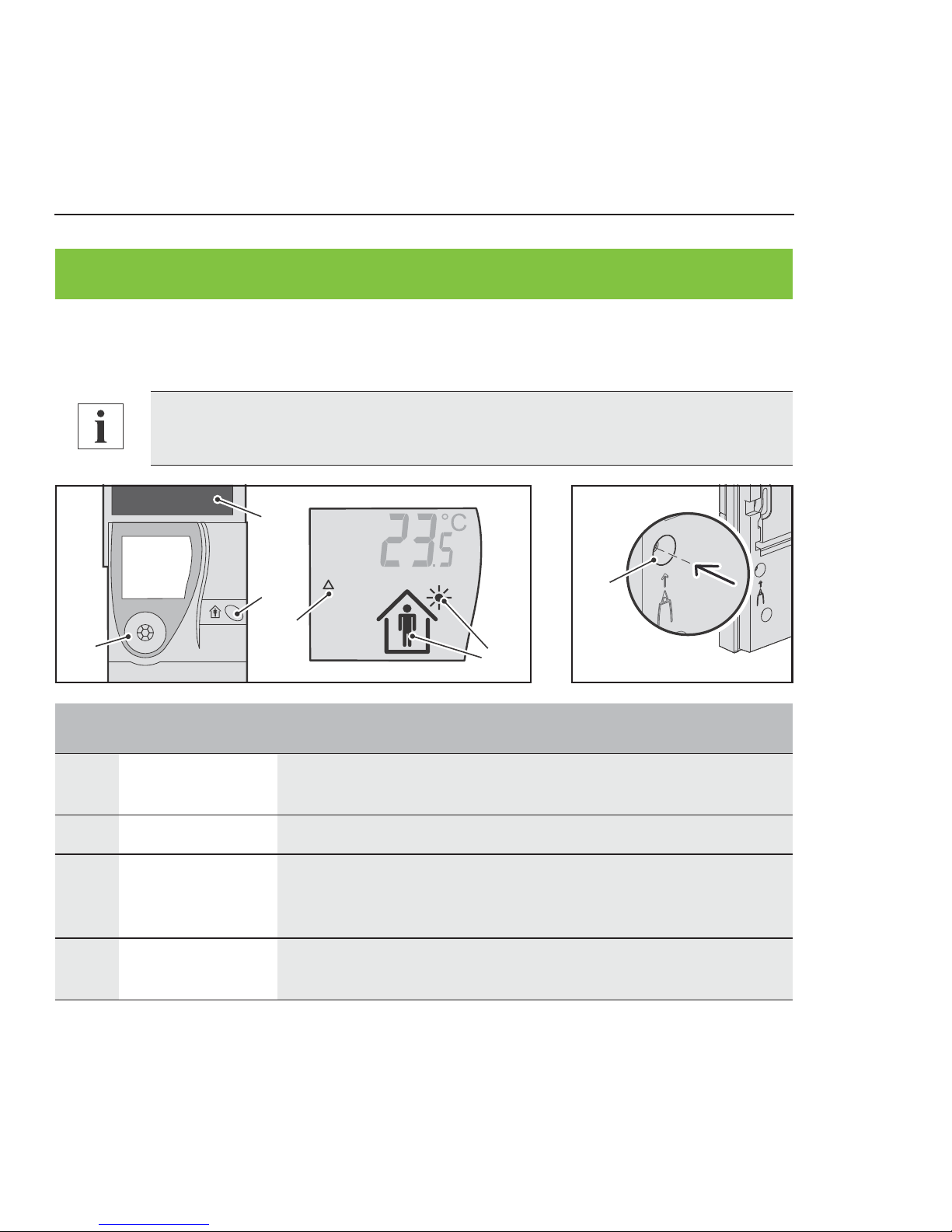
» Testing the installation location
01
04
03
02
04
03
In order to ensure that the occupancy sensor functions correctly, mount the
room sensor at a height of approx. 1.50 m above ground level.
Item Designation Explanation
01 Occupancy
sensor
Detects presence/absence for the heating time profile.
02 Solar cell Generates energy for the room sensor.
03 Occupancy
button +
setting button
Switch on the room sensor when used together.
04 Code, sun,
occupancy
Installation location analysis is active.
Page 13
13/44 Commissioning | en:key
You want to switch on the room sensor and test an installation location for it.
►1 Press the “occupancy button” and the “setting button” simultaneously and
hold them down for 5 seconds.
“rEs” is displayed briefly.
The “Code Δ,” “Sun,” “Occupancy” and temperature icons appear.
The room sensor is switched on; the occupancy sensor and solar cell are
active.
2 Position the room sensor at the potential installation location.
3 Check the “Sun” icon.
4 Move around the room and check the “Occupancy” icon.
If the installation location is good, the room sensor can be mounted there.
If the installation location is bad, the test must be repeated in another location.
Evaluation Display
Installation location
good
The “Sun” icon is displayed permanently, and the “Occupancy” icon switches from “Person inside the house” to
“Person outside the house” and back again
Installation location bad
The “Sun” icon is not displayed or ...
The “Occupancy” icon does not switch to “Person inside the
house” and remains unchanged.
If the room sensor switches off after 15 minutes, switch it back on again.
Page 14
en:key | Commissioning 14/44
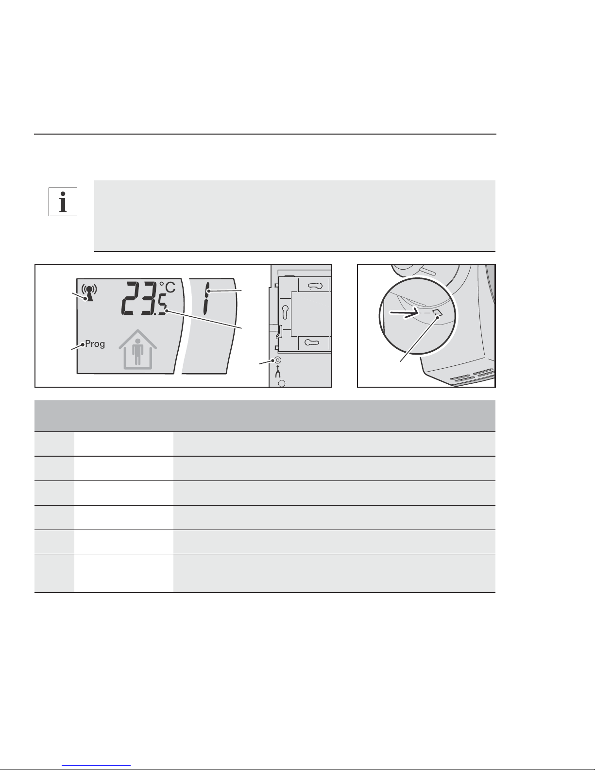
» Registering the valve controller
05
03
04
01
02
06
You want to register one or up to four valve controllers on the room sensor.
It is not possible to disconnect individual valve controllers from the room sen-
sor or register them again once a registration procedure has been com-
pleted. In such cases, all the valve controllers must be registered in a new
procedure.
Item Designation Explanation
01 Antenna Wireless connection system status
02 Prog Valve controllers can be registered
03 Information field Display of the number of registered valve controllers
04 Information field Display of the room temperature, time or messages
05 Setting button Start the registration procedure.
06 Registration
button
Registers the valve controller
Page 15

15/44 Commissioning | en:key
►1 Press the “occupancy button” and the “setting button” simultaneously and
hold them down for 5 seconds.
“rEs” is displayed briefly.
The “Code Δ,” “Sun,” “Occupancy” and temperature icons appear.
The room sensor is switched on; the occupancy sensor and solar cell are
active.
2 Briefly press the “setting button” on the room sensor.
The “Antenna” icon flashes. The “Prog” icon appears.
The room sensor is ready to receive.
3 Within 15 seconds, briefly press the “registration button” on the valve
controller.
The valve controller acknowledges startup with one signal tone shortly
afterwards.
The valve controller acknowledges successful registration with two signal
tones.
Room sensor shows the number of registered valve controllers.
The “Antenna” icon appears permanently. The “Prog” icon disappears.
The “Code Δ” and “Sun” icons disappear after the first data exchange and the
“Auto” icon appears.
Pressing the “registration button” for longer, i.e., until your press is acknowl-
edged with a signal tone, switches the valve controller off. Registration was
not successful and must be repeated.
To register up to three additional valve controllers, briefly press the “registra-
tion button” of the next valve controller within 15 seconds.
Page 16

en:key | Commissioning 16/44
The en:key room set is now in operation, and controls the room temperature in accordance
with the current heating time profile (default/learned).
» Mounting the room sensor
01
02
04
03
05
If the valve controller acknowledges the registration with a series of tones or
if “Code Δ2” appears on the display, the registration was not successful, and
must be repeated.
Up to 10 minutes may elapse before the first data exchange. If the room sen-
sor switches off after 15 minutes, registration was not successful and must
be repeated.
Caution
Flush mounted cabling and piping at the installation location
(electricity, gas, water).
Cabling and piping can be damaged by drilling.
► Check the installation location for flush mounted piping and
cabling, or contact a specialist.
Page 17

17/44 Commissioning | en:key
You want to bond or screw the wall mount to a wall.
►1 Push in the bar on the wall mount and slide the wall mount down on the room
sensor.
2 Remove the “wall mount” from the room sensor.
3 Hold the “wall mount” in place at the installation location.
4 Mark the position of the “wall mount” or the positions of two opposite
mounting holes on the wall.
Item Designation Explanation
01 Adhesive pad Bonds the wall mount to even surfaces
02 Fastening material Select based on surface
(Not included in scope of delivery)
03 Adhesive digits Identifies room sensor and wall mount
04 Holding bar Holds the room sensor in place on the wall mount
05 Wall mount Room sensor wall fastening
For a lasting bond, remove any dust and grease from the adhesive surfaces
on the wall mount and the wall.
Position the wall mount so that the bar can be easily accessed. Ensure a dis-
tance of at least 10 cm from other objects (door frames, electrical sockets,
cupboards, etc.).
Observe the alignment of the wall mount. The bar must be mounted on the
lower right side.
Page 18

en:key | Commissioning 18/44
5a Screws: Drill two mounting holes in the marked positions.
6a If necessary, insert wall plugs into the mounting holes.
7a Hold the wall mount against the wall in the marked position and screw the wall
mount in place tightly, making sure that it is aligned correctly.
Go to item 8.
5b Bonding: Remove a protective film from the adhesive pad and stick it to the
smooth side of the wall mount.
6b Remove the second protective film from the adhesive pad and press the wall
mount onto the marked position on the wall, making sure it is aligned correctly.
7b Press the “wall mount” onto the surface repeatedly and firmly.
The pressing force is more important than the duration.
8 Check the “wall mount” is mounted and aligned correctly on the wall.
9 Mark the room sensor and the wall mount with a unique number using the
enclosed adhesive numbers.
10 Place the room sensor on the wall mount.
11 Slide the room sensor down up to the stop.
The “holding bar” on the “wall mount” clicks audibly into place.
» Mounting the valve controller
The valve controller is fastened directly onto radiator valves with an M30x1.5 DIN 13
connection (e.g. Heimeier, Honeywell, Cazzaniga, Oventrop - 1998 or later).
If several room sensors are removed from their rooms, identifying them with
a number makes it easier to find the correct room. The valve controller does
not need to be re-registered then.
Page 19

02
03
01
04
10 Nm
19/44 Commissioning | en:key
Fastening the valve controller
The valve controller is fastened onto the radiator valve using an octagon nut (M30x1.5 DIN
13).
Item Designation Explanation
01 Radiator valve Controls the heat supply for the radiator
02 Octagon nut Fastens the valve controller to the radiator valve
03 Rotary knob Adjusts comfort temperature
04 Flange Connection to the radiator valve
Do not attach the flange and the octagon nut to the radiator valve in a tilted
position. If they are attached in a tilted position, the power supply from the
thermoelectric generator cannot be guaranteed.
The valve controller must not come into contact with the radiator when
mounted. If the valve controller and radiator come into contact with one
another, the power supply from the thermoelectric generator cannot be guar-
anteed.
Page 20

en:key | Commissioning 20/44
You want to fasten the valve controller onto a radiator valve.
►1 Remove the old thermostat head from the radiator valve.
2 Turn the “rotary knob” on the valve controller to the maximum setting.
3 Ensure that the valve controller is not tilted when mounted on the “radiator
valve”.
4 Tighten the “octagon nut” on the “radiator valve.”
5 Check that the valve controller is seated correctly on the radiator valve.
6 Turn the “rotary knob” to the comfort temperature you want.
Page 21

OPERATION
21/44 Operation | en:key
» Setting the comfort temperature
01
02
03
12°C
14°C
16°C
20°C
24°C
28°C6°C
The time taken to reach the selected room temperature depends on the radi-
ator and the size of the room.
In exceptional cases, settings on the heating system or insufficient radiator
size can result in the set comfort temperature not being reached.
Item Designation Explanation
01 Setting mark Marks the active setting (comfort temperature)
02 Scale Setting for the comfort temperature
03 Rotary knob Adjusts comfort temperature
Page 22

en:key | Operation 22/44
Increasing the comfort temperature
It is too cold for you, and you want to increase the comfort temperature.
►1 Turn the “rotary knob” to a higher setting.
The room temperature rises to the set comfort temperature.
Lowering the comfort temperature
It is too warm for you, and you want to lower the comfort temperature.
►1 Turn the “rotary knob” to a lower setting.
The room temperature drops to the set comfort temperature.
» Changing to comfort mode/economy mode
04
01
03
02
Item Designation Explanation
01 Occupancy
button
Manually switches to comfort mode/economy mode
02 Auto Heating time profile is active (default/learned)
03 Occupancy Person in house – comfort mode
Page 23

23/44 Operation | en:key
Changing to comfort mode
You want to change to comfort mode.
►1 Briefly press the “occupancy button.”
The “Occupancy” icon changes to “Person in house.”
The “Auto” icon disappears.
Economy mode changes to comfort mode.
The manually selected comfort mode stays on for 2 hours, then the learned heating time
profile reactivates and the “Auto” icon appears.
Changing to economy mode
You want to change to economy mode.
►1 Briefly press the “occupancy button.”
The “Occupancy” icon changes to “Person outside.”
The “Auto” icon disappears.
Comfort mode changes to economy mode.
The manually selected economy mode stays on for 4 hours, then the learned heating time
profile reactivates and the “Auto” icon appears.
04 Occupancy Person outside – economy mode
Item Designation Explanation
Page 24

en:key | Operation 24/44
» Start/change/end vacation mode
02
03
04
010501
You want to start vacation mode for 01 to 31 days or change the specified duration.
►1 Press and hold the “occupancy button” for 5 seconds.
The “Time/date” and “Vacation” start displays appear alternately.
Item Designation Explanation
01 Occupancy but-
ton
Start/change vacation mode
02 Vacation Start display of vacation mode
03 Duration Current duration of vacation mode
04 Occupancy Empty house - vacation mode
05 Code U Vacation mode display activated
Briefly pressing the “occupancy button” increases the current setting by +1.
Holding down the “occupancy button” continuously increases the displayed
value.
Page 25

25/44 Operation | en:key
2 Briefly press the occupancy button in the “Vacation” start display to change to
vacation mode.
The “Duration” display flashes (current value).
3 Briefly press the occupancy button to activate the “Duration” display and then
press it several times until the appropriate vacation duration appears.
Vacation duration: 00 to 31days.
4 Do not press the occupancy button again.
„Code U” appears after approx. 3 seconds. Vacation mode activated.
Comfort mode/economy mode changes to vacation mode after 00:00.
You want to deactivate vacation mode immediately.
►1 Set the “Duration” display to 00.
The time or current room temperature appears after approx. 3 seconds.
The “Occupancy” icon changes to “Person in house”
Vacation mode is deactivated immediately and the heating time profile is
active again.
» Changing the time and date
04
03
05
02
01
The room sensor has a time and date (CET - Central European Time). The time and date
are set in the factory and do not need to be entered manually.
The time is automatically adjusted for daylight saving/standard time.
Page 26

en:key | Operation 26/44
You want to change the time and date.
►1 Press and hold the “occupancy button” for 5 seconds.
The “Time/date” and “Vacation” start displays appear alternately.
2 Briefly press the “occupancy button” when the “Time/date” is displayed.
The “Hour/day” display flashes (current hour).
3 Press the “occupancy button” just once to confirm the displayed hour, or
multiple times until the current hour appears.
The “Minute/month” display flashes after approx. 3 seconds (current minute).
Item Designation Explanation
01 Occupancy but-
ton
Change/enter time and date
02 Time/date Start display of time and date
03 Hour/day Display of hour, day
04 Minute/month Display of minute, month
05 Year Display of year
Briefly pressing the “occupancy button” increases the current setting by +1.
Holding down the “occupancy button” continuously increases the displayed
value.
If, when making settings, the “occupancy button” is not pressed for more
than 10 seconds, the display switches back to the old display. Any settings
that were previously made are not saved.
Page 27

27/44 Operation | en:key
4 Press the “occupancy button” just once to confirm the displayed minute, or
multiple times until the current minute appears.
The “Year” display flashes after approx. 3 seconds (current year).
5 Press the “occupancy button” just once to confirm the displayed year, or
multiple times until the current year appears.
The “Minute/month” display flashes after approx. 3 seconds (current month).
6 Press the “occupancy button” just once to confirm the displayed month, or
multiple times until the current month appears.
The “Hour/day” display flashes after approx. 3 seconds (current day).
7 Briefly press the “occupancy button” to confirm the day displayed or press it
multiple times until the current day appears.
8 Do not press the occupancy button again.
The “Prog” icon appears and lines pass through the “Information field.”
The entries made are saved.
The time or current room temperature appears after approx. 3 seconds.
» Toggling the display
03
04
03
04
02
01
Item Designation Explanation
01 Magnetic contact Switches between room temperature/time
Page 28

en:key | Operation 28/44
You want to always see the time in the information field.
►1 Hold a magnet on the “magnet contact” for 5 seconds.
The “ACt” text appears in the information field and the clock icon appears
The current time is displayed permanently in the “information field“.
You want to always see the room temperature in the information field.
►1 Hold a magnet on the “magnet contact” for 5 seconds .
The “ACt” text appears in the information field, and the “Degrees Celsius” icon
appears
The current room temperature is displayed permanently in the “information field“.
» Restoring the defaults
The delivery state of the room sensor can be restored by resetting it to its defaults. All
information, the learned heating time profile and the radio partners is deleted when defaults
are restored.
02 Magnet Starts toggling between room temperature/time
(Not included in scope of delivery)
03 Degrees Celsius/
clock
Unit for information field
04 Information field Room temperature or time, text
After restoring the defaults, the valve controllers should be registered again,
otherwise the room sensor will switch off after 15 minutes.
→ Registering the valve controller (S.14)
Item Designation Explanation
Page 29

01
03
02
03
29/44 Operation | en:key
In its delivery state, the en:key room set controls the room temperature according to the
default heating time profile until a new heating time profile is taught in.
Default heating time profile:
Comfort mode: 6:00 AM - 8:00 PM, comfort temperature
Economy mode: 8:00 PM - 6:00 AM, economy temperature
You want to reset the room sensor to its defaults.
►1 Press and hold the “setting button” for 5 seconds.
The “dEL” and “rEs” texts briefly appear in the information field.
The “Code Δ,” “Sun” and “Occupancy” icons appear.
The learned heating time profile is deleted; the default heating time profile is
active.
The room sensor is reset to the default settings, and all registered valve controllers are
logged off.
Item Designation Explanation
01 Setting button Start the reset procedure
02 Information field Briefly displays “rEs” when logging off.
03 Code Δ, sun,
occupancy
Installation location analysis is active
Page 30

en:key | Operation 30/44
» Switching off the room sensor, valve
controller
01
02
The room sensor and valve controller do not consume any energy when switched off.
Switching off the room sensor
You want to switch off the room sensor.
►1 Press and hold the “setting button” for 5 seconds.
The “dEL” and “rEs” texts briefly appear in the information field.
The “Code Δ,” “Sun” and “Occupancy” icons appear.
2 Wait 15 minutes, and the room sensor switches off automatically.
In order for the en:key room set to automatically resume normal operation at
the beginning of the next heating period, none of the devices may be
switched off during the summer.
Item Designation Explanation
01 Setting button Switches the room sensor off
02 Registration
button
Switches the valve controller off
Page 31

31/44 Operation | en:key
The room sensor is switched off, reset to the default settings and all registered valve
controllers are logged off.
Switching off the valve controller
You want to switch off the valve controller.
►1 Press and hold the “registration button” for 5 seconds.
The valve controller acknowledges a successful switch-off with a series of
tones.
The valve controller is switched off and the connection to the room sensor is broken.
» Activating the service level
03
04
02
01
Item Designation Explanation
01 Magnetic con-
tact
Activates the service level
02 Magnet Starts toggling to service level
(Not included in scope of delivery)
03 Information field Display of messages
04 Code Number of valve controller, processors
Page 32

en:key | Operation 32/44
You want to activate the service level.
►1 Briefly hold a magnet on the “magnet contact.”
The “ACt” text appears in the information field.
The service level is active and the functions can be selected one after the other.
Registering the valve controller
You want to register one or up to four valve controllers on the room sensor.
►1 Activate the service level and select the “ACt” function.
2 Within 15 seconds, briefly press the “registration button” on the valve
controller.
Item Messages Explanation
03.1 ACt Registering of 1 to 4 valve controllers
03.2 dEL De-registering of all registered valve controllers
03.3 ID, code Display of radio ID and number of valve controller
03.4 rEs Switching off the room sensor
03.5 Version, code Display of software version (processors)
The “dEL” and “ID, code” functions are only visible when the valve controllers
are registered on the room sensor.
Page 33

33/44 Operation | en:key
The valve controller acknowledges startup with one signal tone shortly
afterwards.
The valve controller acknowledges successful registration with two signal
tones.
The “Antenna” icon appears permanently. The “Prog” icon disappears.
The “Code Δ” and “Sun” icons disappear after the first data exchange and the
“Auto” icon appears.
The en:key room set is now in operation, and controls the room temperature in accordance
with the current heating time profile (default/learned).
De-registering registered valve controllers
To de-register all registered valve controllers.
►1 Activate the service level and select the “dEL” function.
2 Press and hold the “setting button” for 5 seconds.
The “Code Δ,” “Sun” and “Occupancy” icons appear.
All registered valve controllers are de-registered and the heating time profile remains the
same.
To register up to three additional valve controllers, briefly press the “registra-
tion button” of the next valve controller within 15 seconds.
If the valve controller acknowledges the registration with a series of tones,
the registration was not successful, and must be repeated.
Up to 10 minutes may elapse before the first data exchange. If the room sen-
sor switches off after 15 minutes, registration was not successful and must
be repeated.
Page 34

en:key | Operation 34/44
Displaying the radio ID
You want to see the radio ID of the valve controller.
►1 Activate the service level and select the “ID, code” function.
The figures show the last 4 digits of the radio ID (e.g.: 934F).
Code “1” to “4” shows the number of the valve controller.
2 Briefly press the registration button.
The next radio ID or the “rEs” function appears.
Switching the room sensor off
You want to switch off the room sensor.
►1 Activate the service level and select the “rEs” function.
2 Press and hold the registration button for 5 seconds.
The “dEL” and “rEs” functions appear and the display goes blank.
The room sensor is switched off, reset to the default settings and all registered valve
controllers are logged off.
Displaying the software version of the room sensor
You want to see the software version of the room sensor.
►1 Activate the service level and select the “Version, code” function.
The software version of processor 1 is displayed (code “1”).
2 Briefly press the registration button.
The software version of processor 2 is displayed (code “2”).
After de-registering the valve controllers, the room sensor switches off after
15 minutes if no other valve controller is registered.
Page 35

MESSAGES
03
04
07
01
02
05
06
35/44 Messages | en:key
Item Icon Explanation
01 Antenna System status, wireless connection malfunctions
02 Battery Energy storage unit system status
03 Windows Rapid temperature drop detected
04 Prog Valve controllers can be registered
05 Sun Solar cell is active, summer mode
06 Occupancy Presence/absence, vacation mode
07 Code System status, malfunctions
Page 36

en:key | Messages 36/44
» System status
Icon State Explanation
Antenna On Fault-free radio connection
Code Δ On Installation location analysis is active
Antenna
Prog
Flashes
On
Room sensor ready
Valve controller registration possible
Antenna
Code Δ1
On
On
Wireless radio connection partly interrupted (> 1 hour)
At least one valve controller is being received
Antenna
Code Δ1
Off
On
Wireless radio connection interrupted (> 1 hour)
No valve controllers are being received
Antenna
Code Δ2
On
On
Wireless radio connection partly interrupted (> 4 hours)
At least one valve controller is being received
Antenna
Code Δ2
Off
On
Initial registration failed or
Wireless radio connection interrupted (> 4 hours)
No valve controllers signaling
Battery On Room sensor, energy storage unit
Charge status < 30%
Windows On Economy mode for a maximum of 30 minutes
Code ΔEOn Valve controller, energy storage unit
Charge status < 30%
Occupancy House only Extended absence, vacation mode
Sun
Occupancy
On
Off
Summer mode
System in energy saving mode
Page 37

37/44 Messages | en:key
» Malfunctions
Transmission function
The room sensor continuously monitors the wireless radio connections. If a transmission
malfunction is detected in the room sensor, “Code Δ8” appears.
►1 Reset the room sensor to its defaults.
“Code Δ8” disappears
→ Restoring the defaults (S.28)
2 Register the valve controllers again.
→ Registering the valve controller (S.14)
System time
The room sensor continuously monitors system time. If a time or date malfunction is
detected in the room sensor, “Code Δ3” appears.
►1 Reset the time and date.
“Code Δ3” disappears
→ Changing the time and date (S.25)
Icon State Explanation
Antenna
Code Δ8
Off
On
Transmission function malfunctioning
Room sensor
Code Δ3On System time malfunctioning
Room sensor
If the room sensor transmission function is continuously malfunctioning, the
valve controllers operate in comfort mode. There is no reduction to economy
mode.
Page 38

OTHER
en:key | Other 38/44
» Care, disposal, service
The room sensor and the valve controllers require no maintenance.
The device should be cleaned with due care. No water must be allowed into the inner
workings of the device.
In accordance with the applicable laws and directives of the European Union countries, the
room sensor and valve controllers should not be disposed of with household waste. This
ensures environmental protection and sustainable recycling or raw materials.
If you have any questions regarding the en:key room set, please contact an authorized
service technician directly.
Caution Housing with a sensitive surface.
Sponges and abrasive cleaning materials lead to scratches and a dulling.
► Clean using a moist, lint-free cloth.
Do not use any abrasive cleaning materials or cleaning products.
Private users should contact their local retailer or local authorities for infor-
mation regarding environmentally safe recycling of old appliances.
Commercial users should contact their supplier and observe the conditions of
the purchase agreement. These devices may not be disposed of together
with other commercial waste.
Packaging that is no longer needed can be recycled along with other paper.
Page 39

39/44 Other | en:key
» Technical data
10,5
9,2
19,7
7,0
R 30,0
91,6
90,0
4,1
153,7
2,5
85,5... 90,5
46,5
Ø 37,5
12,5
M30x1,5 DIN 13
61,8
104,0
Page 40

en:key | Other 40/44
Designation Room sensor
RPW301-FTL
Valve controller
MD10-FTL-HE
Nominal voltage 2.3 V =/0.08 W 3 V =/0.3 W
Power supply Lithium battery (AA) Energy storage unit
Measuring system Digital room temperature sensor
Room temperature: 0 °C.. 40°C, accuracy: 0.1 K
Interface EnOcean wireless protocol (< 10 mW)
Communication cycle: 10 minutes
Connection Service connection None
Protection IP30, protection class III IP30, protection class III
Ambient conditions
(operation)
0 °C.. 50°C ambient temperature
20%.. 85% r.F.
45 °C... 90 °C medium temperature (heating period)
for 20 °C ambient temperature
Ambient condition
(transport, storage)
-20 °C.. 50 °C ambient temperature
5%... 90% r.h., non-condensing
Housing Color: RAL 9010
Weight: 0.220 kg
Color: RAL 9010 / 7035
Weight: 0.390 kg
Mounting Screws, bonding Screws
Page 41

41/44 Other | en:key
Page 42

en:key | Other 42/44
Page 43

Page 44

Saving is Fun
ÄSee www.enkey.de for more information
1.10-60.030-20 - 2016-02-22
Kieback&Peter GmbH & Co. KG
Tempelhofer Weg 50, 12347 Berlin
Telefon 030 600 95 0
Telefax 030 600 95 164
info@enkey.de, www.enkey.de
 Loading...