

Page 1
Issue 2015-01-09
Operating Instructions
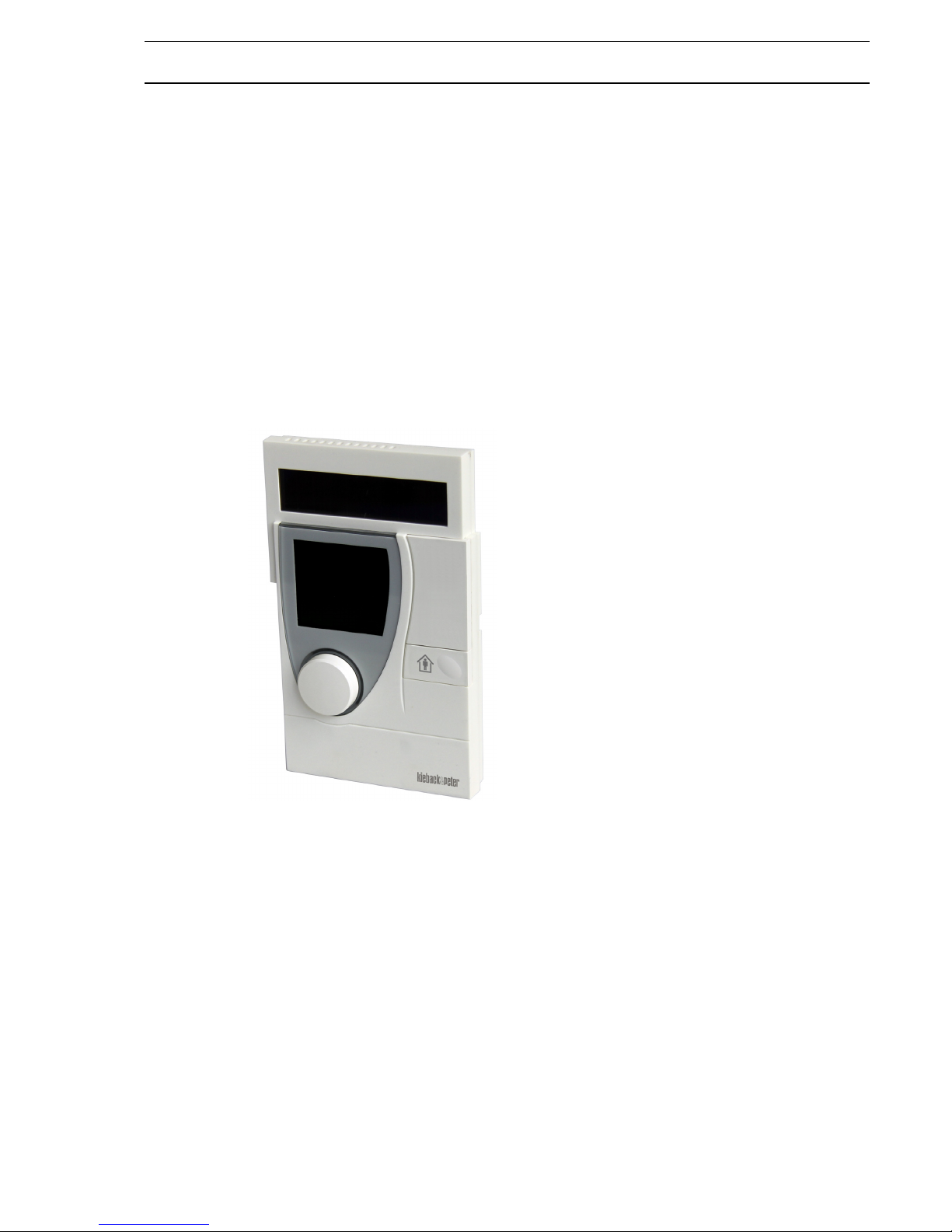
RBW322-FTL-902 Room Control Module
Page 2

2
Issue 2015-01-09
Content Page
1 General Information. . . . . . . . . . . . . . . . . . . . . . . . . . . . . . . . . . . . . . . . . . . . . . . . . . . . . 4
1.1 Information on the operating instructions . . . . . . . . . . . . . . . . . . . . . . . . . . . . . . . . . . . . 4
1.1.1 Validity and storage of the operating instructions . . . . . . . . . . . . . . . . . . . . . . . . . . . . . . 4
1.1.2 Copyright . . . . . . . . . . . . . . . . . . . . . . . . . . . . . . . . . . . . . . . . . . . . . . . . . . . . . . . . . . . . . 4
1.1.3 As an operator, what can you do?. . . . . . . . . . . . . . . . . . . . . . . . . . . . . . . . . . . . . . . . . . 4
1.1.4 Customer service. . . . . . . . . . . . . . . . . . . . . . . . . . . . . . . . . . . . . . . . . . . . . . . . . . . . . . . 5
1.1.5 Notes on presentation in these instructions. . . . . . . . . . . . . . . . . . . . . . . . . . . . . . . . . . . 5
1.2 Scope of Delivery . . . . . . . . . . . . . . . . . . . . . . . . . . . . . . . . . . . . . . . . . . . . . . . . . . . . . . 5
2 Safety . . . . . . . . . . . . . . . . . . . . . . . . . . . . . . . . . . . . . . . . . . . . . . . . . . . . . . . . . . . . . . . 5
2.1 Presentation and structure of warnings . . . . . . . . . . . . . . . . . . . . . . . . . . . . . . . . . . . . . . 5
2.2 Classification of warnings . . . . . . . . . . . . . . . . . . . . . . . . . . . . . . . . . . . . . . . . . . . . . . . . 6
2.3 Intended use . . . . . . . . . . . . . . . . . . . . . . . . . . . . . . . . . . . . . . . . . . . . . . . . . . . . . . . . . . 6
2.4 Responsibilites of the Operator . . . . . . . . . . . . . . . . . . . . . . . . . . . . . . . . . . . . . . . . . . . . 7
3 Equipment Description . . . . . . . . . . . . . . . . . . . . . . . . . . . . . . . . . . . . . . . . . . . . . . . . . . 7
3.1 Components . . . . . . . . . . . . . . . . . . . . . . . . . . . . . . . . . . . . . . . . . . . . . . . . . . . . . . . . . . 8
4 Packaging, transportation and storage . . . . . . . . . . . . . . . . . . . . . . . . . . . . . . . . . . . . . . 8
4.1 Packaging . . . . . . . . . . . . . . . . . . . . . . . . . . . . . . . . . . . . . . . . . . . . . . . . . . . . . . . . . . . . 8
4.2 Transportation . . . . . . . . . . . . . . . . . . . . . . . . . . . . . . . . . . . . . . . . . . . . . . . . . . . . . . . . . 9
4.3 Storage . . . . . . . . . . . . . . . . . . . . . . . . . . . . . . . . . . . . . . . . . . . . . . . . . . . . . . . . . . . . . . 9
5 Operating Modes . . . . . . . . . . . . . . . . . . . . . . . . . . . . . . . . . . . . . . . . . . . . . . . . . . . . . . . 9
6 Controls and Display . . . . . . . . . . . . . . . . . . . . . . . . . . . . . . . . . . . . . . . . . . . . . . . . . . . . 9
6.1 Controls . . . . . . . . . . . . . . . . . . . . . . . . . . . . . . . . . . . . . . . . . . . . . . . . . . . . . . . . . . . . . 10
6.2 Indicators on the display . . . . . . . . . . . . . . . . . . . . . . . . . . . . . . . . . . . . . . . . . . . . . . . . 11
7 Operations and Settings . . . . . . . . . . . . . . . . . . . . . . . . . . . . . . . . . . . . . . . . . . . . . . . . 12
7.1 Summer mode . . . . . . . . . . . . . . . . . . . . . . . . . . . . . . . . . . . . . . . . . . . . . . . . . . . . . . . . 12
7.2 Operating Menu. . . . . . . . . . . . . . . . . . . . . . . . . . . . . . . . . . . . . . . . . . . . . . . . . . . . . . . 12
7.2.1 Selecting the operating menu . . . . . . . . . . . . . . . . . . . . . . . . . . . . . . . . . . . . . . . . . . . . 12
7.2.2 Setting the setpoint . . . . . . . . . . . . . . . . . . . . . . . . . . . . . . . . . . . . . . . . . . . . . . . . . . . . 12
7.3 Configuration Menu . . . . . . . . . . . . . . . . . . . . . . . . . . . . . . . . . . . . . . . . . . . . . . . . . . . . 13
7.3.1 Selecting the configuration menu . . . . . . . . . . . . . . . . . . . . . . . . . . . . . . . . . . . . . . . . . 13
7.3.2 Setting party mode (usage time extension) . . . . . . . . . . . . . . . . . . . . . . . . . . . . . . . . . . 13
7.3.3 Setting vacation mode . . . . . . . . . . . . . . . . . . . . . . . . . . . . . . . . . . . . . . . . . . . . . . . . . . 14
Setting the vacation start . . . . . . . . . . . . . . . . . . . . . . . . . . . . . . . . . . . . . . . . . . . . . . . . 14
Page 3

3
Issue 2015-01-09
Setting the vacation end. . . . . . . . . . . . . . . . . . . . . . . . . . . . . . . . . . . . . . . . . . . . . . . . . 14
Setting the setpoint . . . . . . . . . . . . . . . . . . . . . . . . . . . . . . . . . . . . . . . . . . . . . . . . . . . . 15
Ending an active vacation mode early . . . . . . . . . . . . . . . . . . . . . . . . . . . . . . . . . . . . . . 15
Deleting an inactive vacation mode . . . . . . . . . . . . . . . . . . . . . . . . . . . . . . . . . . . . . . . . 15
7.3.4 Setting the weekly schedule. . . . . . . . . . . . . . . . . . . . . . . . . . . . . . . . . . . . . . . . . . . . . . 15
Deleting a usage time . . . . . . . . . . . . . . . . . . . . . . . . . . . . . . . . . . . . . . . . . . . . . . . . . . 16
7.3.5 Setting the setpoints for comfort mode and economy mode . . . . . . . . . . . . . . . . . . . . . 17
7.3.6 Setting the time and date . . . . . . . . . . . . . . . . . . . . . . . . . . . . . . . . . . . . . . . . . . . . . . . . 17
7.3.7 Setting the time, temperature or setpoint as the initial display. . . . . . . . . . . . . . . . . . . . 18
Setting the 12/24 hour mode . . . . . . . . . . . . . . . . . . . . . . . . . . . . . . . . . . . . . . . . . . . . . 18
Switching the temperature units between °F/°C. . . . . . . . . . . . . . . . . . . . . . . . . . . . . . . 19
8 Maintenance and Cleaning . . . . . . . . . . . . . . . . . . . . . . . . . . . . . . . . . . . . . . . . . . . . . . 19
8.1 Maintenance. . . . . . . . . . . . . . . . . . . . . . . . . . . . . . . . . . . . . . . . . . . . . . . . . . . . . . . . . .19
8.2 Cleaning . . . . . . . . . . . . . . . . . . . . . . . . . . . . . . . . . . . . . . . . . . . . . . . . . . . . . . . . . . . . . 19
9 Malfunctions . . . . . . . . . . . . . . . . . . . . . . . . . . . . . . . . . . . . . . . . . . . . . . . . . . . . . . . . . .19
10 Decommissioning, Removal and Disposal. . . . . . . . . . . . . . . . . . . . . . . . . . . . . . . . . . . 21
10.1 Decommissioning. . . . . . . . . . . . . . . . . . . . . . . . . . . . . . . . . . . . . . . . . . . . . . . . . . . . . . 21
10.1.1 Selecting the service menu . . . . . . . . . . . . . . . . . . . . . . . . . . . . . . . . . . . . . . . . . . . . . . 21
10.1.2 Restoring factory settings. . . . . . . . . . . . . . . . . . . . . . . . . . . . . . . . . . . . . . . . . . . . . . . . 21
10.2 Removal . . . . . . . . . . . . . . . . . . . . . . . . . . . . . . . . . . . . . . . . . . . . . . . . . . . . . . . . . . . . . 22
10.2.1 Screw mounting . . . . . . . . . . . . . . . . . . . . . . . . . . . . . . . . . . . . . . . . . . . . . . . . . . . . . . .22
10.2.2 Adhesive mounting. . . . . . . . . . . . . . . . . . . . . . . . . . . . . . . . . . . . . . . . . . . . . . . . . . . . .22
10.3 Disposal . . . . . . . . . . . . . . . . . . . . . . . . . . . . . . . . . . . . . . . . . . . . . . . . . . . . . . . . . . . . . 23
11 Technical Specifications. . . . . . . . . . . . . . . . . . . . . . . . . . . . . . . . . . . . . . . . . . . . . . . . . 24
11.1 Technical data . . . . . . . . . . . . . . . . . . . . . . . . . . . . . . . . . . . . . . . . . . . . . . . . . . . . . . . . 24
11.2 Dimensions . . . . . . . . . . . . . . . . . . . . . . . . . . . . . . . . . . . . . . . . . . . . . . . . . . . . . . . . . . 25
11.3 Wireless interface. . . . . . . . . . . . . . . . . . . . . . . . . . . . . . . . . . . . . . . . . . . . . . . . . . . . . .25
11.4 Type plate . . . . . . . . . . . . . . . . . . . . . . . . . . . . . . . . . . . . . . . . . . . . . . . . . . . . . . . . . . . 26
12 Appendix . . . . . . . . . . . . . . . . . . . . . . . . . . . . . . . . . . . . . . . . . . . . . . . . . . . . . . . . . . . . 27
13 Contact data. . . . . . . . . . . . . . . . . . . . . . . . . . . . . . . . . . . . . . . . . . . . . . . . . . . . . . . . . .28
Page 4

4 General Information
Issue 2015-01-09
1 General Information
1.1 Information on the operating instructions
These operating instructions contain information on the RBW322-FTL-902 and information on the safe installation, commissioning, handling and correct operation of the device.
The operating instructions are intended for all persons who operate the
RBW322-FTL-902 for the purpose of increasing the reliability and the service life of the
device; it should also help prevent hazards, downtime and possible exclusion of warranty
claims.
Each person who carries out work on the RBW322-FTL-902 must have read and understood these operating instructions.
► If you have any questions that are not resolved by these operating instructions, you
can obtain further information from the supplier or manufacturer.
1.1.1 Validity and storage of the operating instructions
These operating instructions are an integral part of the RBW322-FTL-902 and apply
exclusively to this device.
► Keep the operating instructions in the immediate vicinity of the device throughout the
entire service life of the RBW322-FTL-902.
► The operating instructions must be passed on to any subsequent owners or users.
1.1.2 Copyright
The duplication (even extracts thereof), removal or transfer of content is not allowed
without the manufacturer’s written permission.
1.1.3 As an operator, what can you do?
You may only perform the following actions on the device:
■ Setting the setpoint
■ Setting party mode (usage time extension)
■ Setting vacation mode
■ Setting the weekly schedule
■ Deleting a usage time
■ Setting the setpoints for comfort mode and economy mode
■ Setting the time and date
■ Setting the 12/24 hour mode
■ Switching the temperature units between °F/°C
■ Maintenance and Cleaning
■ Contacting customer service in case of Malfunctions
■ Decommissioning, Removal and Disposal
Page 5
Safety 5
Issue 2015-01-09
NOTE
Mounting, installation, commissioning and troubleshooting may only be performed by a
service technician. Improper changes by the operator can lead to malfunctions and
reduce the service life of the device.
1.1.4 Customer service
If problems occur, if you have questions or if you require technical information, please
contact your service technician.
1.1.5 Notes on presentation in these instructions
Notes contain supplementary information:
NOTE
Indicates additional information and important details that can simplify use of the device.
List symbols
Additional icons are presented in the text to help you follow the operating instructions:
■ Indicates a list item.
► Indicates a step that must be performed.
1.2 Scope of Delivery
The standard scope of delivery includes:
■ RBW322-FTL-902 room control module (incl. batteries)
■ Holding plate
■ Adhesive pad
■ Installation note: RBW322-FTL-902
2 Safety
Always observe the following in order to operate the RBW322-FTL-902 room control
module correctly and safely:
► Read all warnings in these operating instructions in order to prevent injuries and
damage to the device or any equipment connected to it.
► To avoid potential hazards, use the device only as described in the operating instruc-
tions.
► Observe the described actions and warnings in these operating instructions.
► Observe the instructions and warnings in the applicable documents.
2.1 Presentation and structure of warnings
Hazardous situations are displayed with warnings and safety instructions in these operating instructions. Hazard symbols and signal words convey the severity of the hazard.
Page 6
6 Safety
Issue 2015-01-09
The warnings are action-related and are structured as follows.
2.2 Classification of warnings
Warnings are classified according to the severity of the hazard. Hazard levels with their
corresponding signal words and warning symbols are described in the following:
2.3 Intended use
Observe the following to operate the device correctly:
► Do not operate the device in wet or moist environments.
► Do not operate the device in a potentially explosive environment.
► Do not open the device.
► Only operate the RBW322-FTL-902 when it is in original condition.
Modifications to the device could result in unforeseeable dangers and are thus prohibited.
CAUTION
Type/source of danger!
Possible consequences.
► Preventative measures.
CAUTION
The “CAUTION” signal word is used for situations that could result in moderate or
minor injuries.
NOTICE
The “NOTICE” signal word is used for situations that could result in damage to the
device.
Page 7
Equipment Description 7
Issue 2015-01-09
2.4 Responsibilites of the Operator
The device may only be operated if it is technically sound and in safe working order. The
operator must observe the following items:
► Ensure that mounting, installation and commissioning are only performed by service
technicians.
► Ensure that these operating instructions are available to the user.
► Make sure that the user has read the operating instructions before starting work with
the RBW322-FTL-902.
► If the device becomes damaged or if a malfunction message is issued (except when
batteries are changed in the MD15-FTL-902 radio partner), you must inform your
service technician.
3 Equipment Description
You can use the RBW322-FTL-902 room control
module to measure the room temperature in residential or commercial buildings, and to wirelessly
transfer measured values, occupancy, setpoints
and weekly schedules to the MD15-FTL-902 radio
small actuator.
You can manually set or permanently define a
desired setpoint in the device for specific usage or
non-usage periods (weekly schedule).
After the RBW322-FTL-902 has measured the room
temperature, the device wirelessly transmits the
desired room temperature to the MD15-FTL-902.
This controls the room temperature via the radiator
valve.
Page 8
8 Packaging, transportation and storage
Issue 2015-01-09
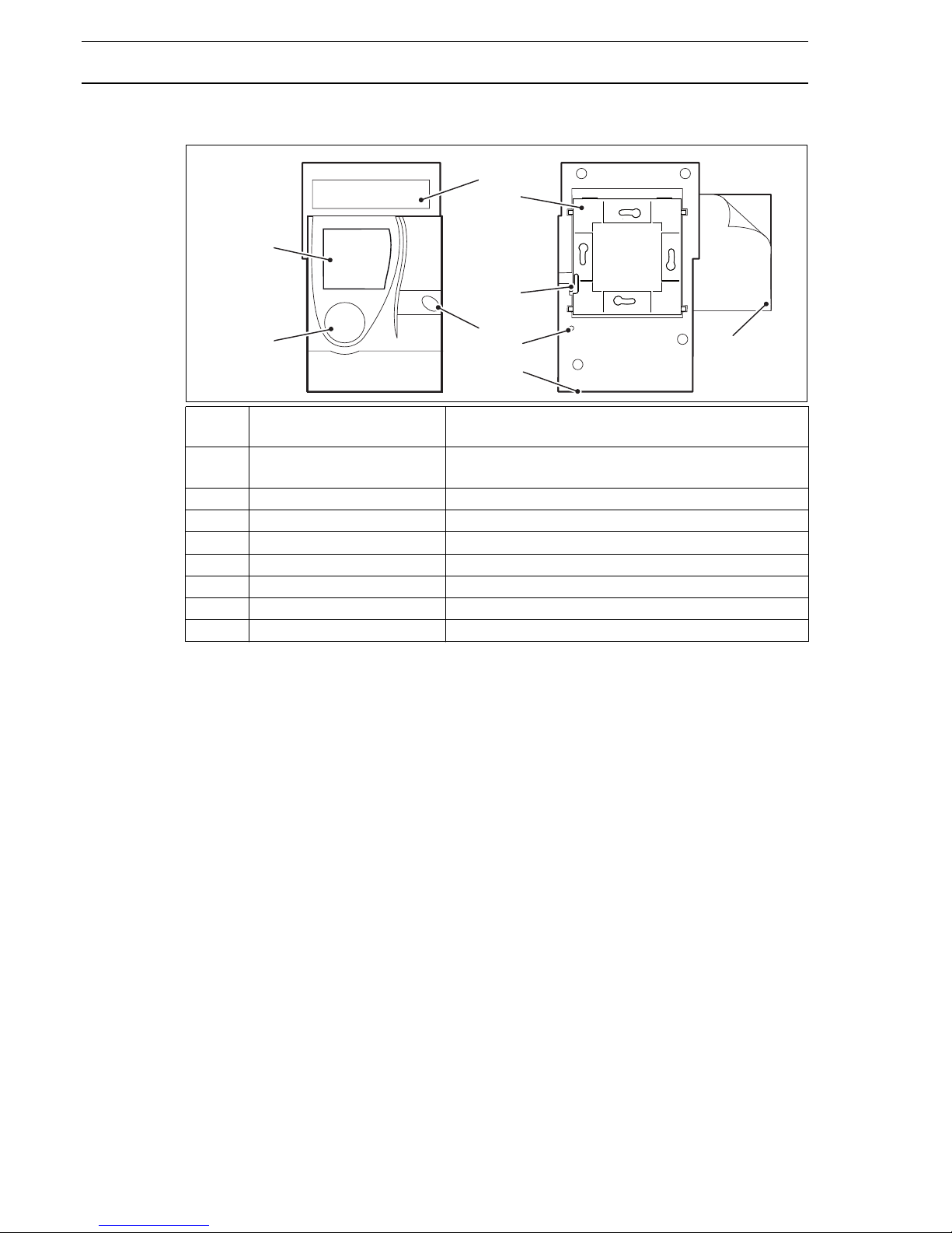
3.1 Components
4 Packaging, transportation and storage
4.1 Packaging
Unpacking
The device is delivered in a cardboard box. When unpacking it, proceed as follows:
► Carefully remove the device from the packaging making sure you do not damage it.
► Dispose of the packaging material according to local regulations.
Repackaging
If you wish to repackage the device for transportation (e.g. for sending a device to the
manufacturer), observe the following points:
► Select an appropriate material for the packaging.
The packaging must not be too large or too small.
► Use packing material to prevent the device from sliding.
► Carefully close and seal the packaging.
01 Display Displays information on the current status of the
RBW322-FTL-902/MD15-FTL-902 functional unit.
02 Setting knob For switching on the device for the first time and
for selecting values.
03 Solar cell Generates energy for device operation
04 Occupancy button Select between “Present” and “Absent”
05 Holding plate Fastens the device to the wall.
06 Holding bar Secures the device to the holding plate.
07 Adhesive pad Sticks the holding plate to even surfaces.
08 Reset interface Restore factory settings.
09 Diagnostics interface
03
04
07
01
02
05
06
08
09
Page 9

Operating Modes 9
Issue 2015-01-09
4.2 Transportation
If you wish to send or transport a device, proceed as follows:
► Transport the device in appropriate packaging.
► Do not throw or toss the packaged device.
► Do not drop the device.
4.3 Storage
If you wish to store the packaged device for a long period of time, you must observe the
following:
► Ensure that the environment is dry.
► Only store the device indoors.
► Store the device in a dust-free environment.
► Protect the device from bumps and mechanical damage.
5 Operating Modes
Because individual rooms are used in different ways, it is important to control the room
temperature according to the particular usage in order to conserve energy. Rooms that
are used in different ways need individual temperature profiles.
There are three different operating modes available that enable you to set a specific room
temperature:
In the configuration menu of RBW322-FTL-902 Room Control Module you can set the
type and date of the operating modes you want to use. See chapter 7.3 “Configuration
Menu”, page 13.
6 Controls and Display
RBW322-FTL-902 and MD15-FTL-902 operate automatically. Basic settings are
performed on the RBW322-FTL-902 room control module only.
Comfort mode: Operating mode for a room that is in use (usage status: “Present”).
The controller operates with the specified comfort setpoint. This
setpoint is set to a comfortable room temperature.
Economy mode: Energy-saving operating mode (usage status: “Absent”/economy
mode) for a room that is not in use. The controller operates with a
predefined lowered or reduced setpoint.
Summer mode: In this operating mode, only economy mode is active. See para-
graph "Summer mode", page 12.
Page 10

10 Controls and Display
Issue 2015-01-09
6.1 Controls
NOTE
If the occupancy button is switched to “Absent” or “economy mode” during an active
usage time, “economy mode” is active until the next switching point (start time) for
“comfort mode” or until the occupancy button is pressed again.
1 Setting knob Turn: Set value (e.g. setpoint).
■ Turn counterclockwise: Reduce value.
■ Turn clockwise: Increase value.
Press (2 seconds): Change menus or
Press (briefly): Set setpoint or confirm display settings
2 Occupancy button Switch between “Present” (comfort mode) and “Absent”
(economy mode).
3 Display Displays information regarding the device status.
4 Solar panel Generates electrical energy for device operation.
1
2
3
4
Page 11

Controls and Display 11
Issue 2015-01-09
6.2 Indicators on the display
The RBW322-FTL-902 has a large display with clear indicators and icons for displaying
current information about the room control module.
1 Time, temperature or
setpoint
Initial display, can be configured
2 Energy storage unit The “Energy storage unit” indicator appears when the
remaining charge of the RBW322-FTL-902 energy storage
unit is < 10%.
3 Weekly schedule Current usage times per day
4 Window-open detec-
tion
The “Window-open detection” indicator appears if a radio
partner transmits this message.
5 Wireless status indica-
tor
Wireless communication icon visible: wireless communica-
tion established, at least one radio partner has been taught
in.
Wireless communication icon not visible: wireless commu-
nication not established, no radio partners have been
taught in or all radio partners are interrupted.
Wireless communication icon flashing: Radiogram trans-
mission/teach-in process.
6 Operating message
and malfunction message
12 or 24 hour display or identification number of the usage
time
7 Vacation mode This icon appears on the display when vacation mode is
activated.
8 Party mode This icon appears on the display when party mode is acti-
vated.
9 Occupancy Indicates if a room is in use or not.
“Person” icon inside the house: The room is in use.
“Person” icon next to the house: The room is not in use.
10 Summer mode This icon appears on the display when summer mode is
activated.
61218240
1
7
8
9
2
3
4
5
10
6
Page 12

12 Operations and Settings
Issue 2015-01-09
7 Operations and Settings
Settings can be made by both the service technician and the operator in the following
working menus. The working menus are not restricted by an access code.
7.1 Summer mode
When the sun icon is displayed, it indicates that the device is operating in summer mode.
The setpoint that has been set for economy mode is used for room
control.
If summer mode is active, the occupancy button, party mode and
weekly schedule are inactive.
Summer mode is automatically activated for the time period from June
01 until August 31. Summer mode can be switched on and off manually using the occupancy button.
► Press the occupancy button for 2 seconds to switch summer mode
on or off.
7.2 Operating Menu
The following functions are available on the operating menu:
■ Setting the setpoint
7.2.1 Selecting the operating menu
You can access the operating menu as follows:
► Press the setting knob briefly.
NOTE
You have two options to set the comfort mode setpoint (operating menu, configuration
menu).
7.2.2 Setting the setpoint
You can only change the set point in comfort mode and for comfort mode.
► Press the setting knob briefly.
The setpoint display flashes for 2 seconds.
► Select the desired setpoint using the setting knob.
The newly selected value flashes and is then automatically applied. Alternatively, you can apply a new value by briefly pressing the setting knob. The
room control module display switches to the initial display.
Page 13

Operations and Settings 13
Issue 2015-01-09
7.3 Configuration Menu
The following functions are available on the configuration menu:
■ Setting party mode (usage time extension)
■ Setting vacation mode
■ Ending an active vacation mode early
■ Deleting or ending vacation mode
■ Setting the weekly schedule
■ Deleting a usage time
■ Setting the setpoints for comfort mode and economy mode
■ Setting the time and date
■ Setting the time, temperature or setpoint as the initial display
■ Setting the 12/24 hour mode
■ Switching the temperature units between °F/°C
7.3.1 Selecting the configuration menu
You can access the configuration menu as follows:
► Press the setting knob for 2 seconds.
► Turn the setting knob clockwise to access the individual setting functions.
NOTE
The individual setting functions are exited if the setting knob is pressed or if no settings
are entered within approx. 30 seconds.
7.3.2 Setting party mode (usage time extension)
Party mode allows you to temporarily extend a usage time by up to eight hours, meaning
that the room continues to be controlled in comfort mode during this time.
The maximum party period is 8 hours.
This can be set in steps of 30 minutes.
► Press the setting knob for 2 seconds.
► Turn the setting knob clockwise.
► Select the “Party mode” function.
► Press the setting knob until the display flashes.
The current time is set as the start of the party mode (usage time extension).
61218240
Page 14

14 Operations and Settings
Issue 2015-01-09
► Turn the setting knob to set the end time for party mode.
The bar display shown indicates the set comfort mode extension (usage time
extension).
► Press the setting knob.
The display switches back to the initial display.
Comfort mode extension is effective immediately. Comfort mode is switched
on.
The party icon in the display indicates that party mode is active.
► Press the occupancy button to end party mode early.
7.3.3 Setting vacation mode
In vacation mode, a room is controlled in reduced temperature mode for a defined time
period of at least 2 days. Vacation mode overwrites/deactivates the set weekly schedule
for the specified time.
► Press the setting knob for 2 seconds.
► Turn the setting knob clockwise to set vacation mode.
► Set vacation start, vacation end and the setpoint for the vacation time
period in the following sequence:
Setting the vacation start
► Press the setting knob.
The month display flashes.
► Set the month by turning the setting knob.
► Press the setting knob.
► Set the day by turning the setting knob.
► Press the setting knob.
Setting the vacation end
► Set the month by turning the setting knob.
► Press the setting knob.
► Set the day by turning the setting knob.
► Press the setting knob.
The display returns to the screen for setting the temperature setpoint for the
vacation period.
61218240
61218240
Page 15

Operations and Settings 15
Issue 2015-01-09
Setting the setpoint
► Set the setpoint for the vacation time.
► Press the setting knob.
The display switches back to the initial display.
Vacation mode begins on the set start date at 12 a.m. and ends on the set
end date at midnight.
If a vacation time is set and has not yet begun, the icon appears on the
initial display.
If vacation mode is active, the vacation end date as well as the icon
appear on the initial display. If vacation mode is active, the controller operates
in economy mode.
Once the set vacation time has elapsed, the vacation mode function is
deleted. The display switches to the initial display.
Ending an active vacation mode early
► Press the setting knob.
Deleting an inactive vacation mode
► Set the vacation start equal to the vacation end.
► Perform the settings as described above.
NOTE
The vacation period must be at least 2 days, and cannot be set retroactively.
If a vacation start is entered which is before the current date, the set dates will not be
active until the next calendar year.
7.3.4 Setting the weekly schedule
You can set up to four usage times per day. A usage time consists of a start time and an
end time (usage time block). This can be set in steps of fifteen minutes.
A weekly schedule is available with the following setting ranges:
■ MOFR Monday - Friday
■ SASU Saturday - Sunday
■ MOSU Monday - Sunday
■ Individual days MO, TU, WE, TH, FR, SA and SU
► Press the setting knob for 2 seconds.
► Use the setting knob to select the “Weekly schedule” function and the
desired weekday range (e.g. MOSU).
61218240
61218240
Page 16

16 Operations and Settings
Issue 2015-01-09
► Press the setting knob.
First usage time/Start time appears on the display and flashes; the icon
is active.
► Turn the setting knob.
► Set the start time.
► Press the setting knob.
First usage time/End time appears on the display and flashes; the icon
is active.
► Turn the setting knob.
► Set the end time.
► Press the setting knob.
The display switches to the start time of the second usage time.
► If necessary, set a second, third and fourth usage time.
The setting procedure is the same as for the first usage time block.
In the display, you can also see which usage time (1) is set.
► Press the setting knob to end the setting of the usage times early.
The bar display shown indicates the usage times of the current day.
If a usage time is active, the controller operates in comfort mode. In addition,
the icon is shown on the display.
Economy mode is active if the current time is outside of the set usage time
block. The icon also appears in the display.
Deleting a usage time
NOTE
Deleting a usage time automatically deletes all subsequent usage times within a
weekday range. Be careful to select the correct weekday range for deletion.
► Select the end time of the usage time block to be deleted as described above.
► Turn the setting knob to the left until the end time is the same as the start time.
► Press the setting knob.
The usage time is deleted and is no longer displayed.
Factory settings: MOSU Monday – Sunday, 6 a.m. - 8 p.m.
61218240
61218240
1
61218240
Page 17

Operations and Settings 17
Issue 2015-01-09
7.3.5 Setting the setpoints for comfort mode and economy mode
► Press the setting knob for 2 seconds.
► Turn the setting knob clockwise.
► Select the “Setpoint” function (temperature display).
► Press the setting knob.
The setpoint for comfort mode flashes and can now be set.
The icon is active.
► Confirm the chosen setpoint for comfort mode by pressing the setting knob.
► The setpoint for economy mode flashes and can now be set.
The icon is active.
► Confirm the chosen setpoint for economy mode by pressing the
setting knob.
7.3.6 Setting the time and date
► Press the setting knob for 2 seconds.
► Use the setting knob to select the “Time + date” function TIME.
► Press the setting knob.
Set the hour, minutes, year, month and day in the following sequence.
The values to be set are always flashing.
Setting the time:
► Set the hour.
► Press the setting knob.
► Set the minutes.
► Press the setting knob.
Setting the date:
► Set the year.
► Press the setting knob.
► Set the month.
► Press the setting knob.
► Set the day.
► Press the setting knob.
Daylight saving time switching occurs automatically according to Central
European standards.
Factory setting: Current Central European time
Factory setting:Comfort mode setpoint: 68 °F (20 °C)
Economy mode setpoint: 59 °F (15 °C)
Page 18

18 Operations and Settings
Issue 2015-01-09
7.3.7 Setting the time, temperature or setpoint as the initial display
► Press the setting knob for 2 seconds.
► Use the setting knob to select the “Setting the initial display” function dISP.
► Press the setting knob.
► Use the setting knob to select the required initial display:
- “Initial display: time”
- “Initial display: temperature” or
- “Initial display: setpoint”
► Press the setting knob.
The display switches to the initial display set by the user.
Default setting: Initial display: time
Setting the 12/24 hour mode
► Press the setting knob for 2 seconds.
► Turn the setting knob clockwise to access the 12/24 hour display.
► Press the setting knob.
► Set the display to 12/24 hours.
► Press the setting knob.
If the 12 hour display (1) is activated, an additional A for AM or P for PM is
shown in the display.
Default setting: 12 hours
61218240
1
Page 19

Maintenance and Cleaning 19
Issue 2015-01-09
Switching the temperature units between °F/°C
► Press the setting knob for 2 seconds.
► Turn the setting knob clockwise. Select the TEMP function to set the
temperature unit °F/°C.
► Press the setting knob.
► Select the desired temperature unit.
► Press the setting knob.
The display switches to the initial display.
Default setting: °F
8 Maintenance and Cleaning
8.1 Maintenance
The RBW322-FTL-902 does not require regular maintenance. If operating or malfunction
messages arise, carry out the actions described in the section “Malfunctions” on page 19.
8.2 Cleaning
The RBW322-FTL-902 should be cleaned as necessary. There is no prescribed cleaning
interval.
► Clean the RBW322-FTL-902 with a lint-free, lightly moistened cloth.
► Do not use any aggressive cleaning products.
9 Malfunctions
The room control module provides information about the current status of the
RBW322-FTL-902/MD15-FTL-902 functional unit and any malfunctions that have
occurred. The operating and malfunction messages are shown on the display.
Icon on display
Problem Solution
■ Radio communication with at
least one taught-in radio
partner has been interrupted for
more than one hour.
■ The wireless status indicator is
no longer displayed if wireless
communication to all taught-in
radio partners is interrupted.
► Check the battery level of the
MD15-FTL-902.
► Replace the batteries in the
MD15-FTL-902 if necessary or
contact your service technician.
Page 20

20 Malfunctions
Issue 2015-01-09
NOTE
Operating and malfunction messages have priority over the 12/24 hour display.
■ Radio communication with at
least one taught-in radio
partner has been interrupted for
more than four hours and a
synchronization has failed.
■ The wireless icon is also no
longer displayed if wireless
communication to all taught-in
radio partners is interrupted.
► Check the battery level of the
MD15-FTL-902.
► Replace the batteries in the
MD15-FTL-902 if necessary or
contact your service technician.
■ Wireless communication to the
taught-in EnOcean system
gateway is interrupted.
■ The battery level of at least one
MD15-FTL-902 is too low
(<10%).
■ If no signal is received from the
MD15-FTL-902 for a long
period of time because the
batteries are dead, the display
switches to .
► Replace the batteries in the
MD15-FTL-902. For more information, see the operating
instructions for the
MD15-FTL-902.
■ Room control module faulty,
supersedes all other
messages.
► Please contact your service
technician.
■ The wireless status indicator is
not displayed.
■ No wireless connection exists.
■ No taught-in radio partner
exists.
■ All radio partners are faulty.
► Please contact your service
technician.
Page 21

Decommissioning, Removal and Disposal 21
Issue 2015-01-09
10 Decommissioning, Removal and Disposal
10.1 Decommissioning
The RBW322-FTL-902/MD15-FTL-902 functional unit must be decommissioned before
transportation, storage or long periods of disuse.
For decommissioning, you must reset the device to the factory settings. With these
settings, the device no longer sends out wireless signals.
► Decommission all MD15-FTL-902 actuators.
► Perform a reset on the service menu to restore the factory settings as described
below:
10.1.1 Selecting the service menu
► Press the setting knob for 2 seconds.
► Use the setting knob to select the “Service menu” SR.
► Press the setting knob.
► Enter the four-digit access code 4321.
Each digit is entered individually and confirmed by briefly pressing the setting
knob.
If you enter the access code incorrectly, the display ER appears.
► Press the setting knob.
10.1.2 Restoring factory settings
► In the service menu, use the setting knob to select the “Restore factory
settings” RES function.
► Press the setting knob.
The display flashes.
► Press the setting knob again.
The “Restore factory settings” function is carried out.
All settings are reset to factory settings, the taught-in radio partners are deleted. The
device returns to its initial state and can be decommissioned.
Page 22

22 Decommissioning, Removal and Disposal
Issue 2015-01-09
10.2 Removal
10.2.1 Screw mounting
If you want to remove the room control module, proceed as follows:
► Insert the flat screwdriver into the notch between the room
control module and the holding plate on the right side.
► Use the flat screwdriver to press the holding bar and release the
connection.
► Slide the room control module upward.
► Separate the room control module from the holding plate.
► Remove the screws by turning the flat screwdriver in counter-
clockwise direction.
10.2.2 Adhesive mounting
If you want to remove the room control module, proceed as follows:
NOTICE
Damage to the mounting surface!
If an adhesive pad other than the one supplied is used, or the mounting surface is textured and does not offer sufficient load-bearing capacity, the mounting surface may
become damaged when the adhesive pad is removed.
► Only use the adhesive pad supplied when mounting the holding plate.
► Only adhere the device to smooth, resistant surfaces (e.g. tiles) and not on tex-
tured surfaces that can easily become damaged (e.g. textured plaster, woodchip
wallpaper).
Page 23

Decommissioning, Removal and Disposal 23
Issue 2015-01-09
► Insert the flat screwdriver into the notch between the room
control module and the holding plate on the right side.
► Use the flat screwdriver to press the holding bar and release the
connection.
► Slide the room control module upward.
► Separate the room control module from the holding plate.
► Remove the adhesive pad from the wall and the holding plate.
10.3 Disposal
The device RBW322-FTL-902 room control module is an electrical device with lithium
batteries and a solar cell. The RBW322-FTL-902 room control module therefore may not
be disposed of with household waste, it may only be disposed of in appropriate receptacles or at designated collection points.
► Please observe locally applicable laws and regulations.
Page 24

24 Technical Specifications
Issue 2015-01-09
11 Technical Specifications
11.1 Technical data
Power supply Dual power supply consisting of a solar cell and an internal energy
storage unit with priority management
■ Internal energy storage uses 2 replaceable 3.6 V AA lithium
batteries
Measured quantity Room temperature in homes or offices
Measuring system Integrated digital sensor
Temperature units °F or °C, can be configured
Measuring range 32..122 °F (0..50 °C)
Relative measurement precision
0.1 K
Display LCD:
■ Time
■ Weekly schedule
■ Icon to indicate operating mode
■ Setpoint in the temperature units selected
50..85 °F, resolution 1 °F
(10.0..30.0 °C, resolution 0.1 K)
Controls
■ Setting knob with confirmation button for setting: Setpoint, party
mode, vacation mode, weekly schedule, time, date, display
options (e.g. 12/24 hour display) and service data
■ Occupancy button: Manually switch between present or
absent
Interfaces between
the
RBW322-FTL-902
and the
MD15-FTL-902
technoLink® wireless interface:
■ Radiogram: EnOcean radiogram, bidirectional
■ Frequency: 902.875 MHz
■ Duty cycle: < 1 %
■ Cyclic transmission or reception intervals
Transmission
power
< 10 mW
Illuminance for
solar cell
Min. 150 lux recommended
Operating range Approx. 30 m in buildings (depending on building substance)
Housing Plastic housing, RAL 9010 (pure white)
Other colors on request
Protection class III
Page 25

Technical Specifications 25
Issue 2015-01-09
11.2 Dimensions
NOTE
The figure shows the dimensions of the device in mm.
11.3 Wireless interface
Wireless communication with the MD15-FTL-902 is cyclical, bidirectional and includes an
intelligent teach-in process.
If the wireless communication between the RBW322-FTL-902 and the MD15-FTL-902 is
interrupted, a new teach-in procedure is automatically triggered internally.
NOTE
This device uses only EnOcean radiograms.
Only the MD15-FTL-902 can be used as a radio partner.
Degree of protection
IP30
Ambient temperature
32..122 °F (0..50 °C)
Ambient humidity During operation: 20..85 % r.h., non-condensing
Out of operation: 5..90 % r.h.; non-condensing
Installation Flexible mounting using screws or adhesive
Weight 0.22 kg
Dimensions WxHxD: 90 x 153.7 x 26.7 mm
3.6
3.5
0.4
0.4
0.80.2
6.5
0.3
R 1.8
0.1
Page 26

26 Technical Specifications
Issue 2015-01-09
11.4 Type plate
The RBW322-FTL-902 type plate is located on the back of the device, behind the holding
plate.
01 RBW322-FTL-902 type plate
02 Serial number
03 Identification number
04 Frequency
05 Device approval number (USA)
06 Device name
01
03
02
04
06
05
Page 27

Appendix 27
Issue 2015-01-09
12 Appendix
Compliance statement
This device complies with section 15 of the FCC Rules. Operation is subject to the
following two conditions: (1) This device may not cause harmful interference, and (2) this
device must accept any interference that may cause undesired operation.
Modifications not expressly approved by this company could void the user’s authority to
operate the equipment.
Radio Frequency (RF) Signal
The radio device is a radio transmitter and receiver. It is designed and manufactured not
to exceed the emission limit for exposure to radio frequency (RF) energy set by the OET
Bulletin 56 Supplement C in the USA and by the Ministry of Health (Canada), Safety
Code 6 in Canada. These limits are part of comprehensive guidelines and established
permitted levels of RF energy population. These guidelines are based on the safety standards previously set by international standard bodies. These standards include a
substantial safety margin designed to assure the safety of all persons, regardless of their
ages and health.
This device and its antenna may not be located too close to or operated in conjunction
with any other antenna or transmitter.
This device is capable of compliance with localized specific absorption rate (SAR) for
uncontrolled environment/general public exposure limits specific in ANSI/IEEE
C95.1-1992 and has been tested in accordance with the measurement procedures specified in IEEE Std. 1528-2003 December 2003.
Class A digital device or peripheral
The RBW322-FTL-902 is a digital device that is marketed for use in a commercial, industrial or business environment, exclusive of a device which is marketed for use by the
general public or intended to be used in the home.
The equipment has been tested and found to comply with the limits for a class A digital
device, pursuant to section 15 of the FCC Rules. These limits are designed to provide
reasonable protection against harmful interference when the equipment is operated in a
commercial environment. This equipment generates, uses, and can radiate radio
frequency energy and, if not installed and used in accordance with the function manual,
may cause harmful interference with radio communications. Operation of this equipment
in a residential area is likely to cause harmful interference in which case the user will be
required to correct the interference at his or her own expense.
Declaration Concerning Antenna Specifications
The device confirms to the FCC recommendations for internal antenna type described
below:
Model No. of antenna: N/A
Page 28

28 Contact data
Issue 2015-01-09
13 Contact data
USA
Magnum Energy Solutions LLC
43 Village Way #209
Hudson, OH 44236
(+1) (330) 656 9365 (telephone)
(+1) (866) 271 3961 (toll free)
(330) 656 9368 (fax)
Type of antenna: integrated/onboard PCB-antenna, permanently
attached
Gain of the antenna: ≤ -10 dBi
Frequency range: 902 MHz
Page 29

Contact data 29
Issue 2015-01-09
Page 30

30 Contact data
Issue 2015-01-09
 Loading...