

Page 1
Kieback&Peter GmbH & Co. KG
Tempelhofer Weg 50, 12347 Berlin/Germany
Telefon: +49 30 60095-0, Telefax: +49 30 60095-164
www.kieback-peter.de, info@kieback-peter.com
Datasheet 1.10-60.315-09-EN
RBW322-FTL-315
Issue 2012-08-16
A
Änderungen vorbehalten - Contents subject to change - Sous réserve de modifications - Reservado el derecho a modificación - Wijzigingen
voorbehouden - Con riserva di modifiche - Innehåll som skall ändras - Změny vyhrazeny - Zmiany zastrzeżone - Возможны изменения
-
A változtatások jogát fenntartjuk -
保留未经通知而改动的权力
User Manual
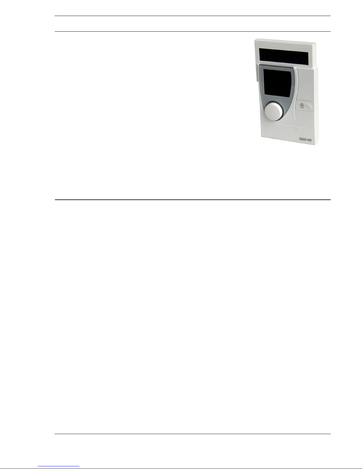
RBW322-FTL-315 Room Control Module
Application
Solar-powered room control module with LCD and controls, with intelligent communication management for measuring room temperature
and for wireless transmission of measured values, occupancy, setpoint
and weekly schedule.
For direct communication with the technoLink® MD15-FTL-315 wireless
small actuator, the RBW322-FTL-315 supports the non-proprietary
EnOcean wireless protocol A5-20-01 (Battery Powered Actuator) using
an integrated wireless interface.
Together with the MD15-FTL-315 function units, the RBW322-FTL-315
constitutes a functional unit for easy room temperature control.
The user manual of the RBW322-FTL-315 and the MD15-FTL-315 are
valid related closely. Follow the instructions and explanations in both
user manuals.
Content Page
General Information ...............................................................................................................................................2
Information about the Manual..............................................................................................................................2
Symbol Declaration..............................................................................................................................................3
Safety.....................................................................................................................................................................4
Equipment Description...........................................................................................................................................5
Components ........................................................................................................................................................5
Operating Modes ................................................................................................................................................. 6
Operation Elements and Display .........................................................................................................................7
Operations and Settings ........................................................................................................................................9
Operating Level ...................................................................................................................................................9
Configuration Level..............................................................................................................................................9
Maintenance and Cleaning ..................................................................................................................................14
System Malfunction .............................................................................................................................................15
Operating and Malfunctioning Messages ..........................................................................................................15
Technical Specifications ......................................................................................................................................16
Contacting Kieback&Peter Representatives........................................................................................................20
Page 2
A
Page 2 / 22
User ManualRBW322-FTL-315
Datasheet 1.10-60.315-09-EN Issue 2012-08-16
General Information
Information about the Manual
This manual contains information on the product RBW322-FTL-315 and its operation. Each person
who carries out work on this product must have read and understood this manual. If you have any
questions that are not resolved by this manual, you can obtain further information from your service
technician.
If the product is not used in accordance with this data sheet, the intended protection will be impaired.
Therefore, please observe the following items without fail:
► This manual is an integral part of the device. Please keep it in the immediate vicinity of the device.
► The manual must be retained throughout the entire service life of the device.
► The manual must be passed along to any subsequent owner or user.
NOTE
This manual describes the specific settings and functions of the RBW322-FTL-315. In addition to
these instructions, the product description of the MD15-FTL-315 wireless partner must also be
observed.
Copyright
Reproduction (including excerpts), recovery or transfer of any content without a written declaration of
the manufacturer is not allowed.
Notes on Disposal
The product is considered waste from electrical and electronic equipment (electronic waste) and may
not be disposed of as household waste. Special treatment for specific components may be legally
binding or ecologically sensible. The local and currently applicable legislation must be observed.
Page 3
A
Page 3 / 22
Datasheet 1.10-60.315-09-EN
RBW322-FTL-315User Manual
Issue 2012-08-16
Symbol Declaration
Safety Instructions
Hazardous situations during installation, commissioning and operating the device are indicated by
safety instructions. They are indicated by signal words which express the severity of the hazard.
Notes
Supplementary information can be found in the notes:
NOTE
Indicates additional information and important details that can simplify working with the product.
Enumeration Signs
There are two other signs which make this manual easier to use:
■ Indicates a list point.
► Indicates an activity you have to do.
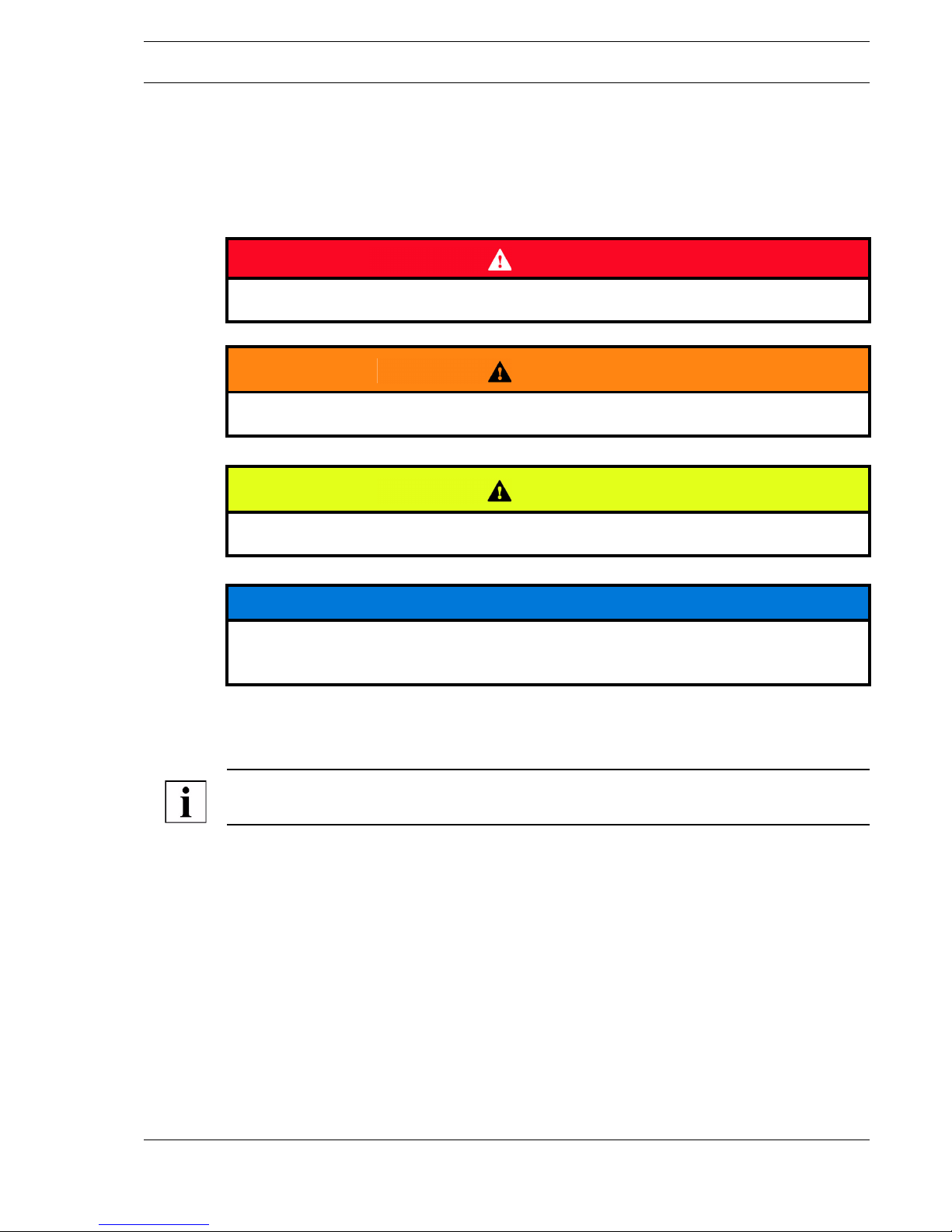
DANGER!
Indicates a hazardous situation which, if not avoided, will result in death or serious injury.
WARNING
Indicates a hazardous situation which, if not avoided, could result in death or serious injury.
CAUTION
Indicates a hazardous situation which, if not avoided, may result in minor or moderate injury.
NOTICE
Warns against a possible hazardous situation that could lead to property and environmental
damage.
Page 4
A
Page 4 / 22
User ManualRBW322-FTL-315
Datasheet 1.10-60.315-09-EN Issue 2012-08-16
Safety
Safety Instructions
To minimize hazards to life and limb, the environment and the machine safety, please observe the
following items:
► Read all safety instructions in this manual in order to prevent injuries and damage to the device
or any equipment connected to it.
► To avoid potential hazards, only operate the product according to its intended use.
► Observe these notes as well as the safety instructions in the following sections of this manual.
Intended Use
Together with the MD15-FTL-315, the RBW322-FTL-315 constitutes a functional unit for easy room
temperature control.
Only the MD15-FTL-315 actuator is authorized for use.
Modifications to and retrofitting of the device could result in unforeseeable dangers and are thus
prohibited.
Please also observe the following items:
► Do not operate the device under wet or moist ambient conditions.
► Do not operate the device in a potentially explosive atmosphere.
► Keep the product surface clean and dry.
As an Operator, What May You Do?
You may only perform the following settings on the device:
■ Setting the setpoint. (See “Setting Setpoint” on page 9.)
■ Set the party mode. (See “Setting Party Mode (Usage Time Extension)” on page 10.)
■ Setting the vacation mode. (See “Setting Vacation Mode” on page 10.)
■ Setting the weekly schedule. (See “Setting the Weekly Schedule” on page 11.)
■ Delete usage time. (See “Delete usage time” on page 12.)
■ Setting the setpoints for comfort mode and reduced temperature mode. (See “Setting the Setpoints
for Comfort Mode and Reduced Temperature Mode” on page 12.)
■ Setting the time and date. (See “Setting the Time and Date” on page 13.)
■ Setting the 12/24 hour display. (See “Setting the 12/24 Hour Display” on page 13.)
■ Switching the temperature unit to °C/°F. (See “Switching the Temperature Units °C/°F” on
page 14.)
■ Maintenance and cleaning. (See “Maintenance and Cleaning” on page 14.)
■ Information about contacting customer service in case of operating and malfunction messages.
(See “Operating and Malfunctioning Messages” on page 15.)
NOTE
Mounting, installation, commissioning and troubleshooting may only be performed by a service
technician. Improper changes by the operator can lead to malfunction and impairment of the service
life.
Customer Service
For technical information or in the case of problems, please contact your service technician. You can
find the contact information on the back of the manual.
Page 5
A
Page 5 / 22
Datasheet 1.10-60.315-09-EN
RBW322-FTL-315User Manual
Issue 2012-08-16
Equipment Description
Along with the MD15-FTL-315 units, the RBW322-FTL-315 constitutes a functional unit for room
temperature control. It is used for controlling the temperature in residential and commercial areas
(households, office buildings, hotels, school buildings under specific circumstances).
Before both wireless partners can communicate with each other, the MD15-FTL-315 must be
teached-in on the RBW322-FTL-315. This procedure only needs to be performed once. Generally,
both wireless partners can be automatically synchronized with each other after a connection failure,
e.g. as caused by malfunctions (See “System Malfunction” on page 15.).
Control of the RBW322-FTL-315/MD15-FTL-315 controller set is assumed by the RBW322-FTL-315.
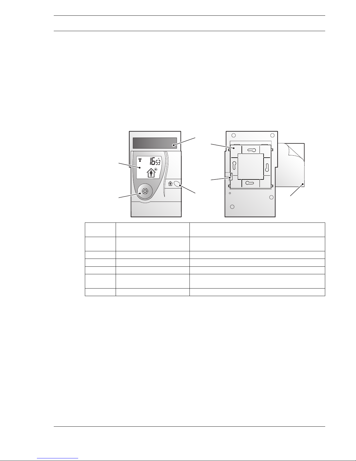
Components
01 Display Displays information on the current status of controller
set RBW322/MD15.
02 Rotary knob When switching on the device for the first time and to
select values.
03 Solar cell Generates energy for internal energy storage units
04 Occupancy button Select between “Present” and “Absent”
05 Holding plate Fastens the RBW322-FTL-315 operator panel
06 Bar Fastens the RBW322-FTL-315 operator panel to the
holding plate
07 Adhesive pad Bonds the holding plate to even surfaces
03
04
07
01
02
05
06
Page 6

A
Page 6 / 22
User ManualRBW322-FTL-315
Datasheet 1.10-60.315-09-EN Issue 2012-08-16
Operating Modes
Because different rooms are used in different ways, temperature control based on use is more
energy-efficient. Rooms that are used in different ways need different temperature profiles.
In order to maintain a desired a temperature in a room, two different operating modes can be used:
Configurations
These operating modes are determined by following configurations, which can be set in the configuration level of the room control module:
Comfort Mode: Operating mode for a room that is in use (“present” mode). The controller
operates with the specified comfort setpoint. The room temperature remains
set in a comfortable range.
Reduced Temperature Mode:
Energy-saving operating mode (“absent”/economy mode) for a room that is
not in use. The controller operates with a reduced setpoint.
Weekly Schedule
MOFR:
The timetable with comfort mode or reduced temperature mode is set from
Monday to Friday.
Weekly Schedule
SASU:
The timetable with comfort mode or reduced temperature mode is set for
Saturday and Sunday
Weekly Schedule
MOSU:
The timetable with comfort mode or reduced temperature mode is set from
Monday to Sunday
Party Mode: You can use the comfort mode longer than registered in the timetable for a
maximum of 8 hours after the comfort mode ends.
Vacation Mode: If you do not use the room for a longer period of time you can set the days in
which you are not present. The room control module will use the reduced
temperature mode on these days.
Page 7
A
Page 7 / 22
Datasheet 1.10-60.315-09-EN
RBW322-FTL-315User Manual
Issue 2012-08-16
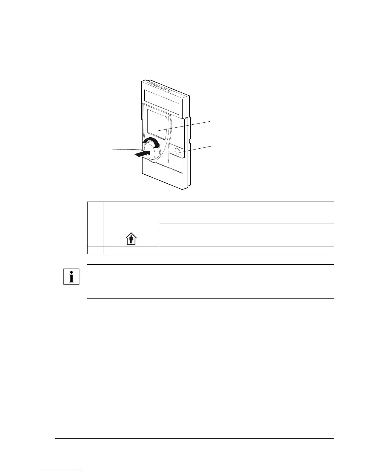
Operation Elements and Display
The RBW322-FTL-315 and MD15-FTL-315 operate automatically. Basic settings are performed on
the RBW322-FTL-315 operator panel.
NOTE
If the occupancy button is switched to “absent” (reduced temperature mode) during an active usage
time, the reduced temperature mode is active until the next switching point (start time) for “comfort
mode”.
1 [Rotary knob]
+
[Confirmation button]
Turn: Set value (e.g. setpoint).
Turn counter-clockwise: Reduce value.
Turn clockwise: Increase value.
Press: Change levels or confirm display setting.
2 Occupancy button: Switch between “Present” (comfort mode) and
“Absent” (reduced temperature mode).
3 Display Displays the most current information of the room control module.
1
2
3
Page 8

A
Page 8 / 22
User ManualRBW322-FTL-315
Datasheet 1.10-60.315-09-EN Issue 2012-08-16
Indicators on the Display
To show the latest information of the room control, the RBW322-FTL-315 has a large display with
clear indicators and symbols.
1 Time Initial display
2 Energy storage indicator The indicator appears when the remaining charge of the
RBW322-FTL-315 energy storage unit is < 10%.
3 Weekly schedule Current daytime usage times
4 Operating message and
malfunction message
12 or 24 hour display or the number of the usage time
5 Wireless control indicator Wireless icon shown = wireless communication present, at least
one wireless partner has been teached-in
Wireless icon not shown = no wireless communication present, no
wireless partners have been teached-in or all wireless partners are
malfunctioning.
Wireless icon flashes = radiogram in transmission / teach-in pro-
cess.
6 Vacation mode indicator This icon appears on the display when vacation mode is activated.
7 Party mode This icon appears on the display when party mode is activated.
8 Occupancy indicator Indicates whether a room is occupied or not.
The person is in the house: The room is in use.
The person is next to the house: The room is not in use.
61218240
1
6
7
8
2
3
4
5
Page 9

A
Page 9 / 22
Datasheet 1.10-60.315-09-EN
RBW322-FTL-315User Manual
Issue 2012-08-16
Operations and Settings
At the operating and configuration level you can configure and set the RBW322-FTL-315 according
to your requirements.
Operating Level
In the operating level you can choose the setpoint for the comfort mode.
You can reach the operating level in the following way:
► Press the rotary knob briefly for 2 seconds.
► Turn it to reach the operating level.
► Press the rotary knob.
NOTE
You have two possibilities to set the setpoint for the comfort mode (operating level, configurating
level).
Setting Setpoint
The setpoint can only be changed in comfort mode .
► Briefly press the rotary knob.
The setpoint indicator flashes for 2 seconds.
► Set the desired setpoint by turning the rotary knob.
The new selected value flashes for approx. 2 seconds; it is then automatically applied
and the room control module switches to the initial display.
A new setpoint can also be applied:
► Press the rotary knob for approx. 2 seconds.
► Set the setpoint by turning the rotary knob.
► Press the rotary knob.
Configuration Level
In the configuration level you can set the party mode, the vacation mode, the weekly schedule, the
setpoint for comfort mode and reduced temperature mode, the time and date, the 12/24 hour display
and you can switch the temperature units °C/°F.
You can reach the operating level in the following way:
► Press the rotary knob briefly for 2 seconds and turn to reach the operation level.
► Turn it to reach the service level.
► Press the rotary knob.
► Turn the rotary knob clockwise to select the individual setting functions, beginning with the party
mode function.
NOTE
The individual setting functions are ended if the rotary knob is pressed for approx. 2 seconds or if no
settings are entered within approx. 30 seconds.
Page 10

A
Page 10 / 22
User ManualRBW322-FTL-315
Datasheet 1.10-60.315-09-EN Issue 2012-08-16
Setting Party Mode (Usage Time Extension)
The maximum party time is 8 hours.
This can be set in steps of 30 minutes.
► Press the rotary knob for 2 seconds.
► Turn the rotary knob clockwise to select the party mode function.
► Press the knob briefly; the display flashes.
Current time = start of party mode (usage time extension).
► Set the end time for party mode (usage time extension) by turning the knob.
The selected comfort mode extension (usage time extension) is shown in the
display by the bar indicator.
► Confirm the entry by briefly pressing the rotary knob.
The display switches back to the initial display.
The comfort mode extension is effective immediately and comfort mode is switched on.
The activated party mode is indicated by the party icon on the display.
► End the party mode prematurely by pressing the occupancy button.
Setting Vacation Mode
► Press the rotary rotary knob for 2 seconds.
► Turn the rotary rotary knob clockwise to set the vacation mode.
Set the Vacation Start
► Briefly press the rotary knob.
The month display flashes.
► Set the month by turning the rotary knob.
► Confirm setting by pressing the rotary knob.
► Set the day by turning the rotary knob.
► Confirm setting by pressing the rotary knob.
Set the Vacation End
► Set the month by turning the rotary knob.
► Confirm setting by pressing the rotary knob.
► Set the day by turning the rotary knob.
► Confirm setting by pressing the rotary knob.
The display switches back to the initial display.
61218240
61218240
61218240
Page 11

A
Page 11 / 22
Datasheet 1.10-60.315-09-EN
RBW322-FTL-315User Manual
Issue 2012-08-16
Vacation mode begins at 00:00 (12 AM) on the set start date and ends at 24:00
(midnight) on the set end date.
If a vacation time is set and has not yet begun, the icon is still shown on the initial
display.
If vacation mode is active, the vacation end date and the icon are shown on the
display. If vacation mode is active, the controller operates in reduced temperature mode.
Once the set vacation time has elapsed, the vacation mode function is deleted and the
display switches back to the initial display.
End an Active Vacation Mode Prematurely
► Press the rotary knob for 2 seconds.
Delete or End Vacation Mode
► Set vacation start equal to vacation end.
Perform settings as described above.
NOTE
Vacation time must be at least 2 days long, and does not work retroactively.
If a vacation start date is entered which is before the current date, the set dates will not be active until
the next calendar year.
Setting the Weekly Schedule
Up to 4 usage times can be set per day. A usage time consists of a start time and an end time
(usage time block). This can be set in steps of 15 minutes.
A weekly schedule is available with the following setting ranges:
■ MOFR Monday - Friday
■ SASU Saturday - Sunday
■ MOSU Monday - Sunday
■ Individual days MO, TU, WE, TH, FR, SA and SU
► Press the rotary knob for 2 seconds.
► Turn the rotary knob clockwise to select the weekly schedule function.
► Press the rotary knob.
First usage time/start time is displayed and flashes, icon is active.
► Turn the rotary knob to set the start time.
► Press the rotary knob to confirm the setting.
First usage time/end time is displayed and flashes, icon is active.
61218240
61218240
61218240
Page 12

A
Page 12 / 22
User ManualRBW322-FTL-315
Datasheet 1.10-60.315-09-EN Issue 2012-08-16
► Turn the rotary knob to set the end time.
► Press the rotary knob to confirm the setting.
The display switches to the start time of the second usage time.
Set the second, third and fourth usage times, if desired.
The setting procedure is the same as for the first usage time block.
The display also shows in which usage time block (1) was just set.
The usage times of the current day are shown by the bar indicator on the display.
If a usage time is active, the controller operates in comfort mode. In addition, this
icon is shown on the display.
If the current time is outside of the set usage time block, reduced temperature mode is
active. In addition, the icon is shown on the display.
Delete usage time
NOTE
Deleting a usage time automatically deletes all subsequent usage times within a day range. So be
careful to select the correct day range for deletion.
► Select the end time of the usage time block to be deleted as described above.
► Turn the rotary knob left until the end time = start time and then press the rotary knob.
The corresponding usage time is deleted and is no longer displayed.
Setting the Setpoints for Comfort Mode and Reduced Temperature Mode
► Press the knob for 2 seconds.
► Turn the knob clockwise to select the setpoint function (temperature display).
► Press the rotary knob.
The setpoint for comfort mode flashes and can now be set.
The icon is active.
► Confirm the chosen setpoint for comfort mode by pressing the rotary knob.
61218240
1
61218240
Page 13

A
Page 13 / 22
Datasheet 1.10-60.315-09-EN
RBW322-FTL-315User Manual
Issue 2012-08-16
► The setpoint for reduced temperature mode flashes and can now be set.
The icon is active.
► Confirm the chosen setpoint for reduced temperature mode by pressing the
rotary knob.
Setting the Time and Date
► Press the rotary knob for 2 seconds.
► Turn the rotary knob clockwise and select the TIME function "Time
+ Date".
► Press the rotary knob.
The hour, minutes, year, month and day can then be set in sequence.
The values to be set are always flashing.
► Set the hour.
► Press the rotary knob and confirm the setting.
► Set the minutes.
► Press the rotary knob and confirm the setting.
► Set the day.
► Press the rotary knob and confirm the setting.
► Set the month.
► Press the rotary knob and confirm the setting.
► Set the year.
► Press the rotary knob and confirm the setting.
Daylight saving time switching occurs automatically according to Central European
standards.
Factory setting: Current Central European Time
Setting the 12/24 Hour Display
► Press the rotary knob for 2 seconds.
► Turn the rotary knob clockwise to access the 12/24 hour display.
► Press the rotary knob.
► Set 12 or 24 hours display.
► Confirm the setting by pressing the rotary knob.
Factory setting: Comfort mode setpoint: 20 °C
Reduced temperature mode setpoint: 15 °C
Page 14

A
Page 14 / 22
User ManualRBW322-FTL-315
Datasheet 1.10-60.315-09-EN Issue 2012-08-16
Set the Vacation Start
► Briefly press the rotary knob.
The month display flashes.
► Set the month by turning the rotary knob.
► Confirm setting by pressing the rotary knob.
► Set the day by turning the rotary knob.
► Confirm setting by pressing the rotary knob.
Factory setting: 24 hours
Switching the Temperature Units °C/°F
► Press the rotary knob for 2 seconds.
► Turn the rotary knob clockwise to select the temperature units °C/°F.
► Press the rotary knob.
► Set the desired temperature units and confirm by pressing the rotary knob.
The display switches to the initial display.
Factory setting: °C
Maintenance and Cleaning
Maintenance
For the RBW322-FTL-315 no maintenance is required.
Cleaning
► Clean the room control module with a lint-free and dry cloth.
► Do not use any aggressive cleaning agents.
61218240
1
Page 15

A
Page 15 / 22
Datasheet 1.10-60.315-09-EN
RBW322-FTL-315User Manual
Issue 2012-08-16
System Malfunction
The room control module provides information about the current status of the RBW322-FTL-315/
MD15-FTL-315 controller set and any occurring malfunctions. The messages are shown on the
display.
Operating and Malfunctioning Messages
NOTE
You will find the contact data of your service technician at the end of the manual. See “Contacting
Kieback&Peter Representatives” on page 20.
Icon on display Problem Solution
■ Wireless communication with at least
one teached-in wireless partner has
been interrupted for more than one
hour.
■ If no signal is received from the
MD15-FTL-315 for a long period of
time because the batteries are dead,
the icon switches to .
■ If wireless communication to all
teached-in wireless partners is interrupted, the wireless icon is also no
longer displayed.
► Report the malfunction to your
service technician.
■ Wireless communication with at least
one teached-in wireless partner has
been interrupted for more than four
hours and a resynchronization has
failed.
■ If wireless communication to all
teached-in wireless partners is interrupted, the wireless icon is also no
longer displayed.
► Report the malfunction to your
service technician.
■ The battery capacity of at least one
MD15-FTL-315 is too low (<10%).
■ If no signal is received from the
MD15-FTL-315 for a long period of
time because the batteries are dead,
the icon switches to ..
► Replace the MD15-FTL-315 bat-
teries.
► When doing this, observe the
section on battery replacement in
the chapter "Operating and Malfunction Messages" in the
MD15-FTL-315 operating instructions.
■ Room control module defective, super-
sedes all other messages.
► Report the malfunction to your
service technician.
■ The battery capacity of the
RBW322-FTL-315 is too low (<10%).
► Report the malfunction to your
service technician.
■ The wireless icon will not be shown.
■ No wireless connection exists!
■ No teached-in wireless partner exists.
■ All wireless partners are defective.
► Report the malfunction to your
service technician.
Page 16

A
Page 16 / 22
User ManualRBW322-FTL-315
Datasheet 1.10-60.315-09-EN Issue 2012-08-16
Technical Specifications
Tec h n i c a l D ata
Power: Dual power supply consisting of a solar cell and an internal energy
storage unit with priority management:
■ Internal energy storage uses 2 replaceable 3.6 V AA lithium batteries
Measured value: Room temperature of spaces in homes or offices
Measuring system: Integrated digital sensor
Temperature units: can be set to °C or °F
Measuring range: 0 to 50 °C or 32 to 122 °F
Relative measurement
precision:
0.1 K
Display: LCD:
■ Time
■ Weekly schedule
■ Icon display to indicate operating mode
■ Setpoint in the temperature units selected
10.0 to 30.0 °C, in 0.1 K increments
or 50 to 85 °F, in 1 °F increments
Controls: Knob with confirmation button for setting: setpoint, party mode, vaca-
tion mode, weekly schedule, time, date, display options (e.g. 12/
24 hour display) and service data
Occupancy button: manually switch between present/absent
Interfaces: technoLink® wireless interface:
■ Wireless telegram: EnOcean wireless telegram, bidirectional
■ Frequency: 315 MHz
■ Operating range: Approx. 1181.1 inches in buildings (depending on
building structure)
■ Duty cycle: < 1%
■ Cyclic transmission/reception intervals
Transmission power: < 10 mW
Illumination strength: Min. 150 lux recommended
Operating range: Approx. 1181.1 inches in buildings (depending on building structure)
Housing: Plastic housing, RAL 9010 (pure white)
Other colors on request
Protection class: III
Degree of protection: IP30
Ambient temperature: 32 to 122 °F
Ambient humidity: During operation: 20 to 85% r.h., non-condensing;
Out of operation: 5 to 90% r.h., non-condensing
Installation: Flexible mounting using screws or adhesive
Weight: 7.76 oz
Dimensions: WxHxD: 3.54 x 6.05 x 1.05 inches
Page 17

A
Page 17 / 22
Datasheet 1.10-60.315-09-EN
RBW322-FTL-315User Manual
Issue 2012-08-16
Dimensions
NOTE
This picture shows the dimension of the device and the radius (R) in inch.
Type plate
The RBW322-FTL-315 type plate is located on the back of the device.
3.61
3.54
0.41
0.36
0.780.16
6.05
0.28
R 1.81
0.098
1 RBW322-FTL-315 type plate
2 Serial number
3 Frequency and nominal voltage
4 Device approval number
5 Identifier of the integrated semiconductor switch
6 Device name
03
02
06
05
04
01
01
RBW322-FtL
RBW322-FtL-315
SN: xxxxxx.yyy
315 MHz 2 x 3,6 V (AA-Lithium)
FCC-ID: NY3RBW322FtL
IC: 10353A-RBW322FtL
Page 18

A
Page 18 / 22
User ManualRBW322-FTL-315
Datasheet 1.10-60.315-09-EN Issue 2012-08-16
Accessories and Spare Parts
NOTE
Contact your Kieback&Peter representative if you have any questions regarding accessories or spare
parts.
Wireless Interface
Wireless communication with the MD15-FTL is cyclical, bidirectional and includes an intelligent
synchronization process.
If the wireless communication between the RBW322-FTL-315 and the MD15-FTL-315 is interrupted,
an internal resynchronization procedure starts automatically.
NOTE
This product uses only EnOcean wireless telegrams.
Only the MD15-FTL-315 can be used as a wireless partner.
Compliance Statement
This device complies with section 15 of the FCC Rules. Operation is subject to the following two
conditions: (1) This device may not cause harmful interference, and (2) this device must accept any
interference that may cause undesired operation.
Modifications not expressly approved by this company could void the user‘s authority to operate the
equipment.
Radio Frequency (RF) Signal
The wireless device is a radio transmitter and receiver. It is designed and manufactured not to exceed
the emission limit for exposure to radio frequency (RF) energy set by the OET Bulletin 56
Supplement C in the USA and by the Ministry of Health (Canada), Safety Code 6 in Canada. These
limits are part of comprehensive guidelines and established permitted levels of RF energy population.
These guidelines are based on the safety standards previously set by international standard bodies.
These standards include a substantial safety margin designed to assure the safety of all persons,
regardless of their ages and health.
This device and its antenna may not be located too close to or operated in conjunction with any other
antenna or transmitter.
This device is capable of compliance with localized specific absorption rate (SAR) for uncontrolled
environment/general public exposure limits specific in ANSI/IEEE C95.1-1992 and has been tested
in accordance with the measurement procedures specified in IEEE Std. 1528-2003 December 2003.
Batteries: 2 replaceable 3.6 V AA lithium batteries
Screws:
(do not use any countersunk-head screws)
Screw head diameter: 2.2 inches
screw head height: 1 inch
nominal diameter: 0.1 inch
Wall plugs: fitting to the specified screws
Two-sided adhesive tape: 3.8 inches x 3.8 inches
Page 19

A
Page 19 / 22
Datasheet 1.10-60.315-09-EN
RBW322-FTL-315User Manual
Issue 2012-08-16
Class A Digital Device or Peripheral
The RBW322-FTL-315 is a digital device that is marketed for use in a commercial, industrial or
business environment, exclusive of a device which is marketed for use by the general public or
intended to be used in the home.
The equipment has been tested and found to comply with the limits for Class A digital device,
pursuant to section 15 of the FCC Rules. These limits are designed to provide reasonable protection
against harmful interference when the equipment is operated in a commercial environment. This
equipment generates, uses, and can radiate radio frequency energy and, if not installed and used in
accordance with the function manual, may cause harmful interference with radio communications.
Operation of this equipment in a residential area is likely to cause harmful interference in which case
the user will be required to correct the interference at his or her own expense.
Declaration Concerning Antenna Specifications
The device confirms to the FCC recommendations for intetnal antenna type described below:
Model No. of antenna: N/A
Type of antenna: integrated/onboard PCB-antenna, permanently attached
Gain of the antenna: ≤ -10 dBi
Frequency range: 315 MHz
Page 20

A
Page 20 / 22
User ManualRBW322-FTL-315
Datasheet 1.10-60.315-09-EN Issue 2012-08-16
Contacting Kieback&Peter Representatives
Canadian Representative
Canadian Radio Standards Consulting Inc.
Kwai Lum
6038 Vineyard Drive, Ottawa, Ontario, K1C2M5
(+) 613-824 6438 (Office)
Lumkwai@rogers.com
US Representative
Magnum Energy Solutions LLC
43 Village Way #209
Hudson, OH 44236
(330) 656 9365 (Office)
(866) 271 3961 (Toll Free)
(330) 656 9368 (Fax)
Page 21

A
Page 21 / 22
Datasheet 1.10-60.315-09-EN
RBW322-FTL-315User Manual
Issue 2012-08-16
Page 22

A
Page 22 / 22
User ManualRBW322-FTL-315
Datasheet 1.10-60.315-09-EN Issue 2012-08-16
 Loading...